EP1997742A2 - Container and dolly - Google Patents
Container and dolly Download PDFInfo
- Publication number
- EP1997742A2 EP1997742A2 EP08251842A EP08251842A EP1997742A2 EP 1997742 A2 EP1997742 A2 EP 1997742A2 EP 08251842 A EP08251842 A EP 08251842A EP 08251842 A EP08251842 A EP 08251842A EP 1997742 A2 EP1997742 A2 EP 1997742A2
- Authority
- EP
- European Patent Office
- Prior art keywords
- container
- wall
- card holder
- dolly
- deck
- Prior art date
- Legal status (The legal status is an assumption and is not a legal conclusion. Google has not performed a legal analysis and makes no representation as to the accuracy of the status listed.)
- Granted
Links
- 230000002093 peripheral effect Effects 0.000 claims description 5
- 230000000717 retained effect Effects 0.000 claims description 2
- 230000000295 complement effect Effects 0.000 abstract description 4
- 230000004048 modification Effects 0.000 description 1
- 238000012986 modification Methods 0.000 description 1
Images









Classifications
-
- B—PERFORMING OPERATIONS; TRANSPORTING
- B65—CONVEYING; PACKING; STORING; HANDLING THIN OR FILAMENTARY MATERIAL
- B65D—CONTAINERS FOR STORAGE OR TRANSPORT OF ARTICLES OR MATERIALS, e.g. BAGS, BARRELS, BOTTLES, BOXES, CANS, CARTONS, CRATES, DRUMS, JARS, TANKS, HOPPERS, FORWARDING CONTAINERS; ACCESSORIES, CLOSURES, OR FITTINGS THEREFOR; PACKAGING ELEMENTS; PACKAGES
- B65D25/00—Details of other kinds or types of rigid or semi-rigid containers
- B65D25/20—External fittings
- B65D25/205—Means for the attachment of labels, cards, coupons or the like
-
- B—PERFORMING OPERATIONS; TRANSPORTING
- B62—LAND VEHICLES FOR TRAVELLING OTHERWISE THAN ON RAILS
- B62B—HAND-PROPELLED VEHICLES, e.g. HAND CARTS OR PERAMBULATORS; SLEDGES
- B62B3/00—Hand carts having more than one axis carrying transport wheels; Steering devices therefor; Equipment therefor
- B62B3/14—Hand carts having more than one axis carrying transport wheels; Steering devices therefor; Equipment therefor characterised by provisions for nesting or stacking, e.g. shopping trolleys
- B62B3/16—Hand carts having more than one axis carrying transport wheels; Steering devices therefor; Equipment therefor characterised by provisions for nesting or stacking, e.g. shopping trolleys vertically stackable
-
- B—PERFORMING OPERATIONS; TRANSPORTING
- B62—LAND VEHICLES FOR TRAVELLING OTHERWISE THAN ON RAILS
- B62B—HAND-PROPELLED VEHICLES, e.g. HAND CARTS OR PERAMBULATORS; SLEDGES
- B62B5/00—Accessories or details specially adapted for hand carts
- B62B5/0083—Wheeled supports connected to the transported object
- B62B5/0093—Flat dollys without hand moving equipment
-
- B—PERFORMING OPERATIONS; TRANSPORTING
- B65—CONVEYING; PACKING; STORING; HANDLING THIN OR FILAMENTARY MATERIAL
- B65D—CONTAINERS FOR STORAGE OR TRANSPORT OF ARTICLES OR MATERIALS, e.g. BAGS, BARRELS, BOTTLES, BOXES, CANS, CARTONS, CRATES, DRUMS, JARS, TANKS, HOPPERS, FORWARDING CONTAINERS; ACCESSORIES, CLOSURES, OR FITTINGS THEREFOR; PACKAGING ELEMENTS; PACKAGES
- B65D21/00—Nestable, stackable or joinable containers; Containers of variable capacity
- B65D21/02—Containers specially shaped, or provided with fittings or attachments, to facilitate nesting, stacking, or joining together
- B65D21/04—Open-ended containers shaped to be nested when empty and to be superposed when full
- B65D21/043—Identical stackable containers specially adapted for nesting after rotation around a vertical axis
- B65D21/045—Identical stackable containers specially adapted for nesting after rotation around a vertical axis about 180° only
-
- B—PERFORMING OPERATIONS; TRANSPORTING
- B62—LAND VEHICLES FOR TRAVELLING OTHERWISE THAN ON RAILS
- B62B—HAND-PROPELLED VEHICLES, e.g. HAND CARTS OR PERAMBULATORS; SLEDGES
- B62B2202/00—Indexing codes relating to type or characteristics of transported articles
- B62B2202/12—Boxes, Crates
-
- B—PERFORMING OPERATIONS; TRANSPORTING
- B62—LAND VEHICLES FOR TRAVELLING OTHERWISE THAN ON RAILS
- B62B—HAND-PROPELLED VEHICLES, e.g. HAND CARTS OR PERAMBULATORS; SLEDGES
- B62B2501/00—Manufacturing; Constructional features
- B62B2501/06—Materials used
- B62B2501/065—Plastics
Definitions
- the present invention relates generally to a stackable and nestable tray.
- One such container includes a holder for a card on the exterior of one end wall.
- the holder includes a small, flexible, clear plastic flap secured to the wall by rivets only at the lower end.
- the flap can be bent downward to insert (or remove) a card that identifies the contents of the container.
- Automated handling equipment bends the card holder flap to remove and replace the cards. Over time, the flap eventually breaks after repeated flexing.
- Some containers include a complementary dolly for transporting a stack of loaded containers or empty containers.
- the dolly has two fixed casters and two casters that pivot about a vertical axis.
- the upper surface of the dolly includes recesses for receiving the casters of a similar dolly, such that they can be stacked when not in use.
- the user often has to rotate the rotatable casters to align them with the recesses on the dolly below.
- the present invention provides a container having an improved card holder that is more durable and can withstand repeated use without fatigue.
- the card holder in one embodiment includes a flap for holding the card.
- the flap is connected to the container by a hinge.
- the hinge includes a hinge pin and a hinge receiver that permit the card holder to pivot, rather than bend. Flexible arms bias the sheet toward the closed position to retain the card.
- a complementary dolly is also provided with recesses on its upper surface for automatically rotating the rotatable casters of a similar dolly stacked thereon to ensure proper alignment.
- both the card holder and the dolly are both disclosed in the context of a 180 degree stack/nest container, both the card holder and the dolly could be used with other types of containers and both could be used with or without one another.
- Figures 1-11 illustrate a container 10 according to a first embodiment of the present invention.
- the container 10 includes a base 12, a pair of opposed side walls including side wall 14, and a pair of opposed end walls including end wall 16.
- the side walls and end walls include alternating inward and outward offset portions 18.
- the offset portions 18 on the opposed side walls and opposed end walls are arranged such that a like container will nest in the container 10 if rotationally aligned and will stack on the container if rotated 180 degrees relative to the container 10.
- the container 10 includes a card holder 20 connected by a hinge 22 at its lower end to the end wall 16.
- the card holder 20 is shown in the closed position with a card 50 retained between the card holder 20 and the end wall 16.
- the card 50 includes indicia 52 of the contents of the container 10.
- the indicia 52 may be text and/or computer readable indicia, such as a barcode.
- the card holder 20 is clear plastic so that the indicia 52 is readable through the card holder 20.
- the card holder 20 can be pivoted about the hinge 22 to an open position so that a card can be inserted or removed from behind the card holder 20.
- the card holder 20 is shown in Figures 3-5 .
- the card holder 20 includes a flap 26 connected to a hinge pin 28 by a plurality of tabs 30.
- the tabs 30 extend at an obtuse angle from the flap portion 26 and are spaced apart by openings 34 and arches 32.
- Figures 6 and 7 show the container 10 without the card holder 20.
- Cantilevered arms 40 form hinge receivers between recesses 42.
- Each of the recesses 42 is defined by a corresponding arch 32 protruding into the interior of the container 10.
- Each of the arches 32 includes a center opening 44.
- the card holder 20 is attached to the container 10 by snapping the hinge pin 28 under the hinge receivers formed by the arms 40 on the container 10 ( Figure 9 ).
- the arches 32 of the card holder 20 are received in the openings 44 of the recesses 42 on the container 10 ( Figure 10 ).
- the card holder 20 is pulled to the open position (shown) so that a card 50 with information printed or stored thereon can be inserted behind the flap 26.
- the arches 32 of the card holder 20 are compressed, such that the arches 32 bias the flap 26 back toward the closed position when the flap 26 is released.
- the card 50 can then be read through the flap 26.
- the flap 26 itself need not be flexible.
- the card holder 20 is more durable than the previous card holder, even after being opened and closed many times. Additionally, if the card holder 20 does break, it is easily replaced, unlike the previous card holder.
- a container 110 and a card holder 120 according to a second embodiment of the present invention is shown in Figures 12-22 .
- the container 110 includes side walls 114 and end walls 116, 117.
- the container 110 includes offset portions 118 such that the container 110 includes the 180 degree stack/nest feature as does the previous embodiment.
- the card holder 120 is clear plastic so that the indicia 52 on the card 50 is readable through the card holder 120.
- the end wall 116 includes a plurality of vertical slots 150 to which the card holder 120 is attached.
- the container 110 includes a base cover 112 providing a smooth lowermost surface.
- Figures 14-16 show the container 110 without the card holder 120 and without the base cover 112.
- the container 110 includes base wall 113 having a plurality of cross ribs 115 to which the base cover 112 ( Figure 13 ) can be secured.
- the vertical slots 150 in the end wall 116 open downward and are contiguous with openings 152 through the base wall 113.
- FIGS 17-19 show the card holder 120.
- the card holder 120 is molded of a clear plastic and includes a flap 126 integrally molded with connectors 156.
- Each connector 156 includes a rib 158 connecting a flange 156 to the flap 126.
- Each flange 156 includes an enlarged base 168.
- the flap 126 includes a portion of increased thickness 170 around each connector 156 to increase strength and to make the flap 126 fit tightly against the tub end wall surface.
- the card holder 120 is connected to the container 110 by sliding the connectors 156 into the openings 152.
- the ribs 158 slide into the vertical slots 150 until the enlarged base 168 of each connector 156 snaps past the base wall 113 ( Figure 22 ).
- the card holder 120 is pulled outward away from the end wall 116 so that a card 50 ( Figure 12 ) can be inserted.
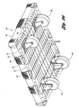
- FIG 23 is a perspective view of a dolly 80 that can be used to carry a plurality of the containers 10, 110 of Figures 1-22 .
- the dolly 80 includes a deck 82. having a generally continuous center upper wall 83 and plurality of protruding locators 84 located around the periphery of the deck 82 and in the center of the deck 82.
- the locators 84 around the periphery are spaced apart by open, ribbed areas 85.
- the upper surface of the deck 82 further includes a plurality of recesses 86 each aligned with casters 88, 89 on the lower side of the deck 82, such that the casters 88, 89 of a similar dolly stacked thereon would be received in the recesses 86 as will be explained below.
- the casters 88 each freely rotate about an axis perpendicular to the deck 82.
- the casters 89 are fixed in a fixed orientation relative to the axis perpendicular to the deck 82.
- the dolly 80 could alternatively have four rotatable casters 88.
- the recesses 86 each include a pair of curved or spherical segments 90 separated by tapered dividers 92.
- Figure 26 is a bottom perspective view of the dolly 80. As shown, the bottom of each of the locators 84 is open. However, the open, ribbed areas 85 ( Figure 24 ) are open so that most of the peripheral portions 93 of the bottom of the deck 82 can be substantially closed (other than small drainage holes).
- the closed peripheral portions 93 of the bottom of the deck 82 facilitates handling by automated handling equipment.
- the closed peripheral portions 93 correspond to the open, ribbed areas 85 ( Figure 23 ) on the upper side of the deck 82.
- the closed locators 84 on the top of the deck 82 ( Figure 23 ) correspond the open areas.
- the remainder of the underside of the deck 82 is defined by ribs 95 extending downwardly from the upper wall 83 ( Figure 23 ) of the deck 82.
Landscapes
- Engineering & Computer Science (AREA)
- Mechanical Engineering (AREA)
- Chemical & Material Sciences (AREA)
- Combustion & Propulsion (AREA)
- Transportation (AREA)
- Stackable Containers (AREA)
- Handcart (AREA)
- Details Of Rigid Or Semi-Rigid Containers (AREA)
Abstract
Description
- The present invention relates generally to a stackable and nestable tray.
- There are known containers that are nestable when oriented alike and stackable when oriented 180 degrees relative to one another. Opposing walls of the containers are complementary, such that walls of a lower container will support a similar container stacked thereon in the 180 degree orientation.
- One such container includes a holder for a card on the exterior of one end wall. The holder includes a small, flexible, clear plastic flap secured to the wall by rivets only at the lower end. The flap can be bent downward to insert (or remove) a card that identifies the contents of the container. Automated handling equipment bends the card holder flap to remove and replace the cards. Over time, the flap eventually breaks after repeated flexing.
- Some containers include a complementary dolly for transporting a stack of loaded containers or empty containers. The dolly has two fixed casters and two casters that pivot about a vertical axis. The upper surface of the dolly includes recesses for receiving the casters of a similar dolly, such that they can be stacked when not in use. However, because two of the casters are rotatable, the user often has to rotate the rotatable casters to align them with the recesses on the dolly below.
- The present invention provides a container having an improved card holder that is more durable and can withstand repeated use without fatigue. The card holder in one embodiment includes a flap for holding the card. The flap is connected to the container by a hinge. The hinge includes a hinge pin and a hinge receiver that permit the card holder to pivot, rather than bend. Flexible arms bias the sheet toward the closed position to retain the card.
- A complementary dolly is also provided with recesses on its upper surface for automatically rotating the rotatable casters of a similar dolly stacked thereon to ensure proper alignment.
- Although the card holder and the dolly are both disclosed in the context of a 180 degree stack/nest container, both the card holder and the dolly could be used with other types of containers and both could be used with or without one another.
- Other advantages of the present invention will be readily appreciated as the same becomes better understood by reference to the following detailed description when considered in connection with the accompanying drawings wherein:
-
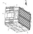
Figure 1 is a perspective view of a container according to a first embodiment of the present invention, with the card holder in the closed position. -
Figure 2 is an enlarged view the container ofFigure 1 , with the card holder in the open position. -
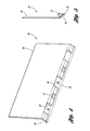
Figure 3 is a perspective interior view of the card holder ofFigure 1 . -
Figure 4 is a perspective exterior view of the card holder ofFigure 1 . -
Figure 5 is a side view of the card holder ofFigure 1 . -
Figure 6 is a perspective exterior view of the container ofFigure 1 without the card holder. -
Figure 7 is a perspective interior view of the container ofFigure 6 . -
Figure 8 is a perspective exterior view of the container ofFigure 1 , with the card holder in the closed position. -
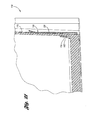
Figure 9 is a section view through the end wall of the container ofFigure 1 , with the card holder in the closed position. -
Figure 10 is a section view through the end wall of the container ofFigure 1 , with the card holder in the closed position. -
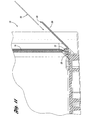
Figure 11 is a section view through the end wall of the container ofFigure 1 , with the card holder in the open position. -
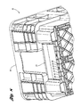
Figure 12 is an upper perspective view of a container according to a second embodiment of the present invention. -
Figure 13 is a lower perspective view of the container ofFigure 12 . -
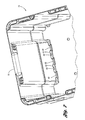
Figure 14 is a lower perspective view of the container ofFigure 12 , without the card holder. -
Figure 15 is an enlarged bottom view of the end wall of the container ofFigure 14 . -
Figure 16 is a perspective interior view the container ofFigure 14 . -
Figure 17 is a perspective view of the interior surface of the card holder ofFigure 12 . -
Figure 18 is a bottom view of the card holder ofFigure 17 . -
Figure 19 is a side view of the card holder ofFigure 17 . -
Figure 20 is an enlarged bottom view of the end wall of the container ofFigure 12 . -
Figure 21 is a section view through the center of the end wall ofFigure 20 . -
Figure 22 is an alternate section view through the end wall ofFigure 20 . -
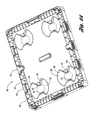
Figure 23 is a perspective view of a dolly that can be used to carry a plurality of the containers ofFigures 1-11 and/orFigures 12-22 . -
Figure 24 is a top perspective view of the dolly ofFigure 23 -
Figure 25 illustrates the alignment of casters from a dolly stacked on the dolly ofFigure 23 . -
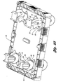
Figure 26 is a bottom perspective view of the dolly ofFigure 23 . -
Figures 1-11 illustrate acontainer 10 according to a first embodiment of the present invention. Thecontainer 10 includes abase 12, a pair of opposed side walls includingside wall 14, and a pair of opposed end walls includingend wall 16. In order to provide the 180 degree stacking and nesting functionality, the side walls and end walls include alternating inward andoutward offset portions 18. Theoffset portions 18 on the opposed side walls and opposed end walls are arranged such that a like container will nest in thecontainer 10 if rotationally aligned and will stack on the container if rotated 180 degrees relative to thecontainer 10. - The
container 10 includes acard holder 20 connected by ahinge 22 at its lower end to theend wall 16. InFigure 1 , thecard holder 20 is shown in the closed position with acard 50 retained between thecard holder 20 and theend wall 16. Thecard 50 includesindicia 52 of the contents of thecontainer 10. Theindicia 52 may be text and/or computer readable indicia, such as a barcode. Thecard holder 20 is clear plastic so that theindicia 52 is readable through thecard holder 20. As shown inFigure 2 , thecard holder 20 can be pivoted about thehinge 22 to an open position so that a card can be inserted or removed from behind thecard holder 20. - The
card holder 20 is shown inFigures 3-5 . Thecard holder 20 includes aflap 26 connected to ahinge pin 28 by a plurality oftabs 30. Thetabs 30 extend at an obtuse angle from theflap portion 26 and are spaced apart byopenings 34 andarches 32. -
Figures 6 and7 show thecontainer 10 without thecard holder 20. Cantileveredarms 40 form hinge receivers betweenrecesses 42. Each of therecesses 42 is defined by acorresponding arch 32 protruding into the interior of thecontainer 10. Each of thearches 32 includes acenter opening 44. - As shown in
Figure 8 , thecard holder 20 is attached to thecontainer 10 by snapping thehinge pin 28 under the hinge receivers formed by thearms 40 on the container 10 (Figure 9 ). Thearches 32 of thecard holder 20 are received in theopenings 44 of therecesses 42 on the container 10 (Figure 10 ). - As shown in
Figure 11 , in use thecard holder 20 is pulled to the open position (shown) so that acard 50 with information printed or stored thereon can be inserted behind theflap 26. When thecard holder 20 is pivoted outward, thearches 32 of thecard holder 20 are compressed, such that thearches 32 bias theflap 26 back toward the closed position when theflap 26 is released. Thecard 50 can then be read through theflap 26. Note that theflap 26 itself need not be flexible. - The
card holder 20 is more durable than the previous card holder, even after being opened and closed many times. Additionally, if thecard holder 20 does break, it is easily replaced, unlike the previous card holder. - A
container 110 and acard holder 120 according to a second embodiment of the present invention is shown inFigures 12-22 . Referring toFigure 12 , thecontainer 110 includesside walls 114 and endwalls container 110 includes offsetportions 118 such that thecontainer 110 includes the 180 degree stack/nest feature as does the previous embodiment. Thecard holder 120 is clear plastic so that theindicia 52 on thecard 50 is readable through thecard holder 120. - As shown in
Figure 13 , theend wall 116 includes a plurality ofvertical slots 150 to which thecard holder 120 is attached. Thecontainer 110 includes abase cover 112 providing a smooth lowermost surface. -
Figures 14-16 show thecontainer 110 without thecard holder 120 and without thebase cover 112. Thecontainer 110 includesbase wall 113 having a plurality ofcross ribs 115 to which the base cover 112 (Figure 13 ) can be secured. Thevertical slots 150 in theend wall 116 open downward and are contiguous withopenings 152 through thebase wall 113. -
Figures 17-19 show thecard holder 120. Thecard holder 120 is molded of a clear plastic and includes aflap 126 integrally molded withconnectors 156. Eachconnector 156 includes arib 158 connecting aflange 156 to theflap 126. Eachflange 156 includes anenlarged base 168. Theflap 126 includes a portion of increasedthickness 170 around eachconnector 156 to increase strength and to make theflap 126 fit tightly against the tub end wall surface. - Referring to
Figures 20-22 , thecard holder 120 is connected to thecontainer 110 by sliding theconnectors 156 into theopenings 152. Theribs 158 slide into thevertical slots 150 until theenlarged base 168 of eachconnector 156 snaps past the base wall 113 (Figure 22 ). - In use, the
card holder 120 is pulled outward away from theend wall 116 so that a card 50 (Figure 12 ) can be inserted. -
Figure 23 is a perspective view of adolly 80 that can be used to carry a plurality of thecontainers Figures 1-22 . Thedolly 80 includes adeck 82. having a generally continuous centerupper wall 83 and plurality of protrudinglocators 84 located around the periphery of thedeck 82 and in the center of thedeck 82. Thelocators 84 around the periphery are spaced apart by open,ribbed areas 85. The upper surface of thedeck 82 further includes a plurality ofrecesses 86 each aligned withcasters deck 82, such that thecasters recesses 86 as will be explained below. Thecasters 88 each freely rotate about an axis perpendicular to thedeck 82. Thecasters 89 are fixed in a fixed orientation relative to the axis perpendicular to thedeck 82. Thedolly 80 could alternatively have fourrotatable casters 88. As shown inFigure 20 , therecesses 86 each include a pair of curved orspherical segments 90 separated by tapereddividers 92. - As shown in
Figure 25 , when a similar dolly (only the casters 88', 89' are shown) is stacked on thedolly 80, the rotational positions of therotatable casters 88 will be re-aligned by the tapereddividers 92 into therecesses 86. The fixed casters 89' on the dolly will be received in therecesses 86 between the tapered divides 92. Thus the dollies can be stacked without regard for orientation of thecasters -
Figure 26 is a bottom perspective view of thedolly 80. As shown, the bottom of each of thelocators 84 is open. However, the open, ribbed areas 85 (Figure 24 ) are open so that most of theperipheral portions 93 of the bottom of thedeck 82 can be substantially closed (other than small drainage holes). The closedperipheral portions 93 of the bottom of thedeck 82 facilitates handling by automated handling equipment. The closedperipheral portions 93 correspond to the open, ribbed areas 85 (Figure 23 ) on the upper side of thedeck 82. Theclosed locators 84 on the top of the deck 82 (Figure 23 ) correspond the open areas. The remainder of the underside of thedeck 82 is defined byribs 95 extending downwardly from the upper wall 83 (Figure 23 ) of thedeck 82. - Although a preferred embodiment of this invention has been disclosed, a worker of ordinary skill in this art would recognize that certain modifications would come within the scope of this invention. For that reason, the following claims should be studied to determine the true scope and content of this invention.
Claims (24)
- A container comprising:a floor;a first wall extending upward from the floor; anda card holder snap-fit to the first wall and pivotable relative to the first wall, the card holder including a flap portion.
- The container of claim 1 wherein the flap portion is clear.
- The container of claim 1 wherein the card holder is a clear plastic.
- The container of claim 1 wherein a similar container can be nested therein when oriented similarly and can be stacked thereon when oriented 180 degrees relative thereto.
- The container of claim 1 wherein the card holder is pivotably secured to the first wall by a hinge, the hinge including a hinge pin snap-fit into a hinge receiver.
- The container of claim 5 wherein the hinge pin is integrally molded with the card holder.
- The container of claim 6 wherein the hinge receiver is formed in the first wall.
- The container of claim 7 wherein the first wall includes at least one arm forming the hinge receiver.
- The container of claim 1 wherein the card holder includes at least one integrally molded connector received in a slot in the first wall.
- The container of claim 9 wherein the slot in the first wall is a vertical slot opening downward.
- The container of claim 10 wherein the connector snap-fits past the floor to connect the card holder to the container.
- The container of claim 1 further including a card with indicia between the card holder and the first wall.
- The container of claim 1 further including second, third and fourth walls extending upward from the floor to define an interior compartment of the container with the first wall.
- A dolly comprising:a deck having a plurality of recesses formed in an upper surface thereof, the recesses each including two curved portions partially separated by tapered dividers; anda plurality of casters extending downward from the deck, each aligned with one of the plurality of recesses.
- The dolly of claim 14 wherein the casters are rotatable about an axis perpendicular to the deck.
- The dolly of claim 14 wherein the plurality of casters include two casters rotatable about an axis perpendicular to the deck and two fixed casters.
- The dolly of claim 14 further including a plurality of locators protruding upwardly from a periphery of the deck.
- The dolly of claim 14 further including a substantially closed peripheral portion about the periphery of the underside of the deck.
- The dolly of claim 18 wherein the deck includes an upper panel down from which a plurality of ribs extend, the peripheral portion corresponding to an upper periphery extending around the periphery of the upper panel, the upper periphery being primarily open, with ribs extending therethrough.
- The dolly of claim 19 further including a plurality of locators protruding upward from the upper periphery of the deck, the locators opening downwardly.
- A container comprising:a floor;a plurality of walls extending upward from the floor to define an interior compartment, the plurality of walls including a first wall, the first wall including an integrally molded hinge receiver; anda card holder including a flap portion and an integrally molded hinge pin snap-fit into the hinge receiver.
- The container of claim 21 wherein the flap portion is clear.
- The container of claim 21 further including a card having indicia thereon, the card retained between the flap portion and the first wall, the indicia readable through the flap portion.
- The container of claim 21 wherein the hinge pin is connected to the flap portion by a flexible arch, the arch biasing the flap portion toward the first wall.
Priority Applications (1)
| Application Number | Priority Date | Filing Date | Title |
|---|---|---|---|
| EP11160024A EP2343228A1 (en) | 2007-05-29 | 2008-05-27 | Container and dolly |
Applications Claiming Priority (1)
| Application Number | Priority Date | Filing Date | Title |
|---|---|---|---|
| US11/754,458 US20080296183A1 (en) | 2007-05-29 | 2007-05-29 | Tray and dolly |
Related Child Applications (1)
| Application Number | Title | Priority Date | Filing Date |
|---|---|---|---|
| EP11160024.3 Division-Into | 2011-03-28 |
Publications (3)
| Publication Number | Publication Date |
|---|---|
| EP1997742A2 true EP1997742A2 (en) | 2008-12-03 |
| EP1997742A3 EP1997742A3 (en) | 2008-12-24 |
| EP1997742B1 EP1997742B1 (en) | 2011-12-21 |
Family
ID=39670683
Family Applications (2)
| Application Number | Title | Priority Date | Filing Date |
|---|---|---|---|
| EP11160024A Withdrawn EP2343228A1 (en) | 2007-05-29 | 2008-05-27 | Container and dolly |
| EP08251842A Not-in-force EP1997742B1 (en) | 2007-05-29 | 2008-05-27 | Container |
Family Applications Before (1)
| Application Number | Title | Priority Date | Filing Date |
|---|---|---|---|
| EP11160024A Withdrawn EP2343228A1 (en) | 2007-05-29 | 2008-05-27 | Container and dolly |
Country Status (3)
| Country | Link |
|---|---|
| US (1) | US20080296183A1 (en) |
| EP (2) | EP2343228A1 (en) |
| CA (1) | CA2628555A1 (en) |
Cited By (15)
| Publication number | Priority date | Publication date | Assignee | Title |
|---|---|---|---|---|
| CN104609003A (en) * | 2015-02-04 | 2015-05-13 | 安徽科技学院 | Finger-type tube fixing specimen box provided with turnover type label and foamed plastic |
| CN104609002A (en) * | 2015-02-04 | 2015-05-13 | 安徽科技学院 | Finger-type tube fixing specimen box provided with flip-type label and bowl supports |
| CN104608999A (en) * | 2015-02-04 | 2015-05-13 | 安徽科技学院 | Use method for finger-type tube fixing specimen box provided with L-shaped label and sliding bowl supports |
| CN104609007A (en) * | 2015-02-04 | 2015-05-13 | 安徽科技学院 | Usage method for expanded plastic fixing finger-type pipe specimen box with L-shaped label |
| CN104609004A (en) * | 2015-02-04 | 2015-05-13 | 安徽科技学院 | Expanded plastic fixing finger-type pipe specimen box with L-shaped label |
| CN104609006A (en) * | 2015-02-04 | 2015-05-13 | 安徽科技学院 | Use method for finger-type tube fixing specimen box provided with turnover type label and foamed plastic |
| CN104608998A (en) * | 2015-02-04 | 2015-05-13 | 安徽科技学院 | Use method for finger-type tube fixing specimen box provided with L-shaped label and bowl supports |
| CN104627492A (en) * | 2015-02-04 | 2015-05-20 | 李吉菊 | Use method of double-faced glass finger type pipe specimen box with L-shaped label |
| CN104627493A (en) * | 2015-02-04 | 2015-05-20 | 安徽科技学院 | Sliding bowl support fixing finger-shaped tube specimen box with flip type tag |
| CN104627489A (en) * | 2015-02-04 | 2015-05-20 | 安徽科技学院 | Using method for double-sided glass finger-shaped tube specimen box with flip type tag |
| CN104627486A (en) * | 2015-02-04 | 2015-05-20 | 安徽科技学院 | Specimen box with flip label and expanded plastics fixing finger type pipes |
| CN104627490A (en) * | 2015-02-04 | 2015-05-20 | 安徽科技学院 | Using method for sliding bowl support fixing finger-shaped tube specimen box with flip type tag |
| CN104627491B (en) * | 2015-02-04 | 2016-08-24 | 安徽科技学院 | A kind of slip bowl care with convertible label fixes the using method of dactylethrae Riker mount |
| WO2016174286A1 (en) * | 2015-04-28 | 2016-11-03 | Matrival, S.L. | Cardholder for containers |
| US10780906B2 (en) | 2016-01-28 | 2020-09-22 | Chep Technology Pty Limited | Dolly for transporting products |
Families Citing this family (9)
| Publication number | Priority date | Publication date | Assignee | Title |
|---|---|---|---|---|
| US8740228B2 (en) * | 2010-08-24 | 2014-06-03 | Rehrig Pacific Company | Dolly with wheel acceptance area |
| JP5684639B2 (en) * | 2011-04-18 | 2015-03-18 | 三菱樹脂株式会社 | Folding container |
| US9205951B1 (en) * | 2014-07-24 | 2015-12-08 | Josephine E. Roman | All-in-one stackable bulletin board caddy |
| US9522763B2 (en) * | 2014-07-24 | 2016-12-20 | Josephine E. Roman | All-in-one stackable bulletin board caddy |
| JP7244893B2 (en) * | 2018-05-24 | 2023-03-23 | 岐阜プラスチック工業株式会社 | Card holders and transport containers with card holders |
| US11173939B2 (en) | 2018-08-20 | 2021-11-16 | Rehrig Pacific Company | Bakery dolly |
| US20200307862A1 (en) * | 2019-03-25 | 2020-10-01 | Jeff Green | Storage container with label |
| UA44462S (en) * | 2020-12-11 | 2021-10-21 | К ГАРТВАЛЛЬ ОЙ АБ | PLATFORM FOR CONTAINER TROLLEY |
| US12558930B2 (en) | 2021-02-08 | 2026-02-24 | Orbis Corporation | Detachable dolly training connector |
Family Cites Families (33)
| Publication number | Priority date | Publication date | Assignee | Title |
|---|---|---|---|---|
| US3529795A (en) * | 1968-06-03 | 1970-09-22 | Eaton Yale & Towne | Fastening device |
| FR2468510A1 (en) * | 1979-10-08 | 1981-05-08 | Allibert Exploitation | EMBEDDED BAC |
| DE3004673A1 (en) * | 1980-02-08 | 1981-08-13 | Fritz Schäfer GmbH Fabriken für Lager- und Betriebseinrichtungen, Salchendorf bei Neunkirchen, Kreis Siegen, 5908 Neunkirchen | TRANSPORT AND / OR STORAGE BOX |
| AU513140B3 (en) * | 1981-02-23 | 1981-04-30 | Pennicook Davison Pty. Ltd. | Container with hinged label window |
| JPH049323Y2 (en) * | 1986-01-17 | 1992-03-09 | ||
| DE3835304C1 (en) * | 1988-10-17 | 1989-10-05 | Sitec Gmbh Sicherheitseinrichtungen Und Technische Geraete, 8641 Weissenbrunn, De | Transport container |
| DK169911B1 (en) * | 1992-12-22 | 1995-04-03 | Rd Impex Aps | Trolley with swivel wheels |
| US5445396A (en) * | 1993-08-09 | 1995-08-29 | Gale Group, Inc. | Nestable dolly construction |
| GB2281897B (en) * | 1993-09-16 | 1997-04-30 | Lin Pac Mouldings | A platform assembly |
| US5823549A (en) * | 1996-01-11 | 1998-10-20 | Morgan, Jr.; George Joseph | Stacking dolly |
| US5772063A (en) * | 1996-04-09 | 1998-06-30 | Gantz-Bloome; Sharon | Waste receptacle with changeable art display capability |
| US5785328A (en) * | 1996-05-03 | 1998-07-28 | Star Metal Products, Inc. | Stackable cart assembly |
| DK174875B1 (en) * | 1997-03-26 | 2004-01-12 | R D Impex As | Stackable trolley with pivotally mounted wheels |
| US6206221B1 (en) * | 1997-09-08 | 2001-03-27 | Uni-Charm Corporation | Covering device |
| US5934695A (en) * | 1997-11-03 | 1999-08-10 | Rowland; Leroy J. | Stackable trailers |
| NL1008867C1 (en) * | 1998-04-10 | 1999-10-12 | Wavin Lash V O F | Plastic pallette with top surface to accommodate wheeled platforms |
| JP3707973B2 (en) * | 1999-11-09 | 2005-10-19 | 三甲株式会社 | Folding container |
| US6257152B1 (en) * | 2000-04-06 | 2001-07-10 | Ching-Rong Liu | Structure of pallet for stacking pallets with wheels |
| JP3500118B2 (en) * | 2000-10-19 | 2004-02-23 | 三甲株式会社 | Transport trolley |
| US6607199B2 (en) * | 2001-04-20 | 2003-08-19 | Rehrig Pacific Company | Tray and dolly assembly |
| US6953116B2 (en) * | 2002-05-03 | 2005-10-11 | Pinckney Molded Plastics, Inc. | Stackable tray having prestressed sections |
| US20030205877A1 (en) * | 2002-05-03 | 2003-11-06 | Donald Verna | Stackable dolly for supporting stackable trays having prestressed sections |
| JP4073245B2 (en) * | 2002-05-09 | 2008-04-09 | 矢崎化工株式会社 | Carriage for transportation |
| US6979005B1 (en) * | 2002-06-17 | 2005-12-27 | Chriscott Supply, Inc. | Stackable dollies and dolly systems |
| US6986434B1 (en) * | 2002-07-25 | 2006-01-17 | Silgan Plastics Corporation | Container closure with hinged lid |
| US6658771B1 (en) * | 2002-08-26 | 2003-12-09 | Liberty Hardware Mfg. Corp. | Replaceable indicia panel for merchandising bin |
| US6959507B2 (en) * | 2002-10-10 | 2005-11-01 | Bazany Donald J | Injection molded, recessed insert for use in a container and method of using same |
| US7131224B1 (en) * | 2003-07-30 | 2006-11-07 | Excelligence Learning Corporation | Storage bin with attachable label holder |
| US7234598B2 (en) * | 2004-03-16 | 2007-06-26 | Schaefer Systems International, Inc. | Material handling container with card holder |
| DE202004015972U1 (en) * | 2004-10-14 | 2004-12-09 | Gebhardt Transport- Und Lagersysteme Gmbh | Roller pallet for transporting goods is composed of a metal frame with cover plate of deep-drawn sheet fixed to it |
| US7424785B2 (en) * | 2004-12-20 | 2008-09-16 | Emc Corporation | Label cassette for an electronics enclosure |
| GB2425999B (en) * | 2005-05-14 | 2009-01-14 | Linpac Materials Handling Ltd | Moulded platform and method of making a moulded platform |
| US7500579B2 (en) * | 2005-09-26 | 2009-03-10 | Crossley David W | Cup with a pill shelf |
-
2007
- 2007-05-29 US US11/754,458 patent/US20080296183A1/en not_active Abandoned
-
2008
- 2008-04-03 CA CA002628555A patent/CA2628555A1/en not_active Abandoned
- 2008-05-27 EP EP11160024A patent/EP2343228A1/en not_active Withdrawn
- 2008-05-27 EP EP08251842A patent/EP1997742B1/en not_active Not-in-force
Non-Patent Citations (1)
| Title |
|---|
| None |
Cited By (22)
| Publication number | Priority date | Publication date | Assignee | Title |
|---|---|---|---|---|
| CN104627486A (en) * | 2015-02-04 | 2015-05-20 | 安徽科技学院 | Specimen box with flip label and expanded plastics fixing finger type pipes |
| CN104627490A (en) * | 2015-02-04 | 2015-05-20 | 安徽科技学院 | Using method for sliding bowl support fixing finger-shaped tube specimen box with flip type tag |
| CN104608999A (en) * | 2015-02-04 | 2015-05-13 | 安徽科技学院 | Use method for finger-type tube fixing specimen box provided with L-shaped label and sliding bowl supports |
| CN104609007A (en) * | 2015-02-04 | 2015-05-13 | 安徽科技学院 | Usage method for expanded plastic fixing finger-type pipe specimen box with L-shaped label |
| CN104609004A (en) * | 2015-02-04 | 2015-05-13 | 安徽科技学院 | Expanded plastic fixing finger-type pipe specimen box with L-shaped label |
| CN104609006A (en) * | 2015-02-04 | 2015-05-13 | 安徽科技学院 | Use method for finger-type tube fixing specimen box provided with turnover type label and foamed plastic |
| CN104608998A (en) * | 2015-02-04 | 2015-05-13 | 安徽科技学院 | Use method for finger-type tube fixing specimen box provided with L-shaped label and bowl supports |
| CN104627492A (en) * | 2015-02-04 | 2015-05-20 | 李吉菊 | Use method of double-faced glass finger type pipe specimen box with L-shaped label |
| CN104627493A (en) * | 2015-02-04 | 2015-05-20 | 安徽科技学院 | Sliding bowl support fixing finger-shaped tube specimen box with flip type tag |
| CN104627491B (en) * | 2015-02-04 | 2016-08-24 | 安徽科技学院 | A kind of slip bowl care with convertible label fixes the using method of dactylethrae Riker mount |
| CN104609002A (en) * | 2015-02-04 | 2015-05-13 | 安徽科技学院 | Finger-type tube fixing specimen box provided with flip-type label and bowl supports |
| CN104609003A (en) * | 2015-02-04 | 2015-05-13 | 安徽科技学院 | Finger-type tube fixing specimen box provided with turnover type label and foamed plastic |
| CN104627489A (en) * | 2015-02-04 | 2015-05-20 | 安徽科技学院 | Using method for double-sided glass finger-shaped tube specimen box with flip type tag |
| CN104627489B (en) * | 2015-02-04 | 2016-09-28 | 何晴雪 | A kind of using method of the double-sided glass dactylethrae Riker mount of band flip-shell label |
| CN104627493B (en) * | 2015-02-04 | 2017-03-29 | 安徽科技学院 | A kind of slip bowl care with flip-shell label fixes dactylethrae Riker mount |
| CN104608999B (en) * | 2015-02-04 | 2017-01-11 | 安徽科技学院 | Use method for finger-type tube fixing specimen box provided with L-shaped label and sliding bowl supports |
| CN104609002B (en) * | 2015-02-04 | 2017-01-18 | 安徽科技学院 | Finger-type tube fixing specimen box provided with flip-type label and bowl supports |
| CN104627486B (en) * | 2015-02-04 | 2017-03-29 | 安徽科技学院 | A kind of foamed plastic with flip-shell label fixes dactylethrae Riker mount |
| WO2016174286A1 (en) * | 2015-04-28 | 2016-11-03 | Matrival, S.L. | Cardholder for containers |
| CN107709178A (en) * | 2015-04-28 | 2018-02-16 | 马彻沃有限责任公司 | Card holder for container |
| EP3290348A4 (en) * | 2015-04-28 | 2018-04-11 | Matrival, S.L. | Cardholder for containers |
| US10780906B2 (en) | 2016-01-28 | 2020-09-22 | Chep Technology Pty Limited | Dolly for transporting products |
Also Published As
| Publication number | Publication date |
|---|---|
| CA2628555A1 (en) | 2008-11-29 |
| US20080296183A1 (en) | 2008-12-04 |
| EP1997742A3 (en) | 2008-12-24 |
| EP2343228A1 (en) | 2011-07-13 |
| EP1997742B1 (en) | 2011-12-21 |
Similar Documents
| Publication | Publication Date | Title |
|---|---|---|
| EP1997742B1 (en) | Container | |
| EP2390199B1 (en) | Collapsible dual height stacking container | |
| US8950581B2 (en) | Stackable container | |
| EP2517971B1 (en) | Material handling device | |
| US6308858B1 (en) | Storage container | |
| US6193340B1 (en) | Snap-together file storage system | |
| AU2018234796B2 (en) | Retail packaging and transport box for small parts, tools, machines or such objects | |
| US9145230B2 (en) | Storage device comprising two parts | |
| EP2353793A1 (en) | Metal and plastic container | |
| US10450104B2 (en) | Storage tote with latching handle | |
| US20010052479A1 (en) | Battery package with multiple support compartments | |
| CN106687256A (en) | Inserts for an assortment box | |
| US11148869B2 (en) | Water resistant tote box | |
| US20050155889A1 (en) | Modular and stackable tray assembly | |
| EP2289811A1 (en) | Collapsible crate | |
| US7234598B2 (en) | Material handling container with card holder | |
| EP4072957B1 (en) | Stackable and nestable container | |
| US6513675B1 (en) | Food container with rigid base plate | |
| US7441673B2 (en) | Material handling container with card holder | |
| US20120217183A1 (en) | Dual insertion plastic shell container | |
| US20250083877A1 (en) | Food Container with Access Tab | |
| EP1555215A1 (en) | Stackable container | |
| EP1357045A1 (en) | Nestable and stackable container | |
| JP2016016880A (en) | Folding container | |
| GB2311769A (en) | Document case |
Legal Events
| Date | Code | Title | Description |
|---|---|---|---|
| PUAI | Public reference made under article 153(3) epc to a published international application that has entered the european phase |
Free format text: ORIGINAL CODE: 0009012 |
|
| PUAL | Search report despatched |
Free format text: ORIGINAL CODE: 0009013 |
|
| AK | Designated contracting states |
Kind code of ref document: A2 Designated state(s): AT BE BG CH CY CZ DE DK EE ES FI FR GB GR HR HU IE IS IT LI LT LU LV MC MT NL NO PL PT RO SE SI SK TR |
|
| AX | Request for extension of the european patent |
Extension state: AL BA MK RS |
|
| AK | Designated contracting states |
Kind code of ref document: A3 Designated state(s): AT BE BG CH CY CZ DE DK EE ES FI FR GB GR HR HU IE IS IT LI LT LU LV MC MT NL NO PL PT RO SE SI SK TR |
|
| AX | Request for extension of the european patent |
Extension state: AL BA MK RS |
|
| 17P | Request for examination filed |
Effective date: 20090213 |
|
| 17Q | First examination report despatched |
Effective date: 20090320 |
|
| AKX | Designation fees paid |
Designated state(s): DE FR GB |
|
| GRAP | Despatch of communication of intention to grant a patent |
Free format text: ORIGINAL CODE: EPIDOSNIGR1 |
|
| RTI1 | Title (correction) |
Free format text: CONTAINER |
|
| GRAS | Grant fee paid |
Free format text: ORIGINAL CODE: EPIDOSNIGR3 |
|
| GRAA | (expected) grant |
Free format text: ORIGINAL CODE: 0009210 |
|
| AK | Designated contracting states |
Kind code of ref document: B1 Designated state(s): DE FR GB |
|
| REG | Reference to a national code |
Ref country code: GB Ref legal event code: FG4D |
|
| REG | Reference to a national code |
Ref country code: DE Ref legal event code: R096 Ref document number: 602008012137 Country of ref document: DE Effective date: 20120216 |
|
| PLBE | No opposition filed within time limit |
Free format text: ORIGINAL CODE: 0009261 |
|
| STAA | Information on the status of an ep patent application or granted ep patent |
Free format text: STATUS: NO OPPOSITION FILED WITHIN TIME LIMIT |
|
| 26N | No opposition filed |
Effective date: 20120924 |
|
| REG | Reference to a national code |
Ref country code: DE Ref legal event code: R097 Ref document number: 602008012137 Country of ref document: DE Effective date: 20120924 |
|
| REG | Reference to a national code |
Ref country code: FR Ref legal event code: ST Effective date: 20130131 |
|
| REG | Reference to a national code |
Ref country code: DE Ref legal event code: R119 Ref document number: 602008012137 Country of ref document: DE Effective date: 20121201 |
|
| PG25 | Lapsed in a contracting state [announced via postgrant information from national office to epo] |
Ref country code: FR Free format text: LAPSE BECAUSE OF NON-PAYMENT OF DUE FEES Effective date: 20120531 |
|
| PG25 | Lapsed in a contracting state [announced via postgrant information from national office to epo] |
Ref country code: DE Free format text: LAPSE BECAUSE OF NON-PAYMENT OF DUE FEES Effective date: 20121201 |
|
| PGFP | Annual fee paid to national office [announced via postgrant information from national office to epo] |
Ref country code: GB Payment date: 20140521 Year of fee payment: 7 |
|
| GBPC | Gb: european patent ceased through non-payment of renewal fee |
Effective date: 20150527 |
|
| PG25 | Lapsed in a contracting state [announced via postgrant information from national office to epo] |
Ref country code: GB Free format text: LAPSE BECAUSE OF NON-PAYMENT OF DUE FEES Effective date: 20150527 |