EP1997713B1 - Motor controller and electric power steering apparatus - Google Patents
Motor controller and electric power steering apparatus Download PDFInfo
- Publication number
- EP1997713B1 EP1997713B1 EP08157183A EP08157183A EP1997713B1 EP 1997713 B1 EP1997713 B1 EP 1997713B1 EP 08157183 A EP08157183 A EP 08157183A EP 08157183 A EP08157183 A EP 08157183A EP 1997713 B1 EP1997713 B1 EP 1997713B1
- Authority
- EP
- European Patent Office
- Prior art keywords
- max
- sin
- phase
- electric current
- cos
- Prior art date
- Legal status (The legal status is an assumption and is not a legal conclusion. Google has not performed a legal analysis and makes no representation as to the accuracy of the status listed.)
- Expired - Fee Related
Links
Images


Classifications
-
- B—PERFORMING OPERATIONS; TRANSPORTING
- B62—LAND VEHICLES FOR TRAVELLING OTHERWISE THAN ON RAILS
- B62D—MOTOR VEHICLES; TRAILERS
- B62D5/00—Power-assisted or power-driven steering
- B62D5/04—Power-assisted or power-driven steering electrical, e.g. using an electric servo-motor connected to, or forming part of, the steering gear
- B62D5/0457—Power-assisted or power-driven steering electrical, e.g. using an electric servo-motor connected to, or forming part of, the steering gear characterised by control features of the drive means as such
- B62D5/0481—Power-assisted or power-driven steering electrical, e.g. using an electric servo-motor connected to, or forming part of, the steering gear characterised by control features of the drive means as such monitoring the steering system, e.g. failures
- B62D5/0487—Power-assisted or power-driven steering electrical, e.g. using an electric servo-motor connected to, or forming part of, the steering gear characterised by control features of the drive means as such monitoring the steering system, e.g. failures detecting motor faults
-
- B—PERFORMING OPERATIONS; TRANSPORTING
- B62—LAND VEHICLES FOR TRAVELLING OTHERWISE THAN ON RAILS
- B62D—MOTOR VEHICLES; TRAILERS
- B62D5/00—Power-assisted or power-driven steering
- B62D5/04—Power-assisted or power-driven steering electrical, e.g. using an electric servo-motor connected to, or forming part of, the steering gear
- B62D5/0457—Power-assisted or power-driven steering electrical, e.g. using an electric servo-motor connected to, or forming part of, the steering gear characterised by control features of the drive means as such
- B62D5/0481—Power-assisted or power-driven steering electrical, e.g. using an electric servo-motor connected to, or forming part of, the steering gear characterised by control features of the drive means as such monitoring the steering system, e.g. failures
- B62D5/0484—Power-assisted or power-driven steering electrical, e.g. using an electric servo-motor connected to, or forming part of, the steering gear characterised by control features of the drive means as such monitoring the steering system, e.g. failures for reaction to failures, e.g. limp home
-
- H—ELECTRICITY
- H02—GENERATION; CONVERSION OR DISTRIBUTION OF ELECTRIC POWER
- H02P—CONTROL OR REGULATION OF ELECTRIC MOTORS, ELECTRIC GENERATORS OR DYNAMO-ELECTRIC CONVERTERS; CONTROLLING TRANSFORMERS, REACTORS OR CHOKE COILS
- H02P21/00—Arrangements or methods for the control of electric machines by vector control, e.g. by control of field orientation
- H02P21/22—Current control, e.g. using a current control loop
-
- H—ELECTRICITY
- H02—GENERATION; CONVERSION OR DISTRIBUTION OF ELECTRIC POWER
- H02P—CONTROL OR REGULATION OF ELECTRIC MOTORS, ELECTRIC GENERATORS OR DYNAMO-ELECTRIC CONVERTERS; CONTROLLING TRANSFORMERS, REACTORS OR CHOKE COILS
- H02P29/00—Arrangements for regulating or controlling electric motors, appropriate for both AC and DC motors
- H02P29/02—Providing protection against overload without automatic interruption of supply
- H02P29/032—Preventing damage to the motor, e.g. setting individual current limits for different drive conditions
Description
- The present invention relates to a motor controller and an electric power steering apparatus.
- In many cases, conventional motor controllers used, for example, in electric power steering apparatuses (EPS) include anomaly detecting means. The anomaly detecting means detects an anomaly when flow of electric current fails in any one of U, V, and W phases, due to a break in power supply lines or damage to contacts of a driver circuit. When such an anomaly is detected, control of operation of a motor is quickly stopped and thus fail safe is performed.
- However, in the EPS, if the control of the operation of the motor is suspended, the steering characteristics are greatly changed. Specifically, increased steering force becomes necessary for the driver to accurately manipulate a steering wheel. In this regard, Japanese Laid-Open Patent Publication No.
2003-26020 - However, with reference to
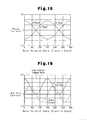
Fig. 15 , if a sinusoidal electric current is supplied to each one of the electric current flowing phases in the above-described conventional case, a torque ripple is caused and thus steering comfort decreases.Fig. 15 illustrates an example in which the electric current flow has failed in the U phase while normal electric current flows are ensured in the V and W phases. - Specifically, as illustrated in
Fig. 16 , if change of a motor electric current in conventional two-phase drive operation is represented in a d/q coordinate system, a q-axis current command value, which is a target control value of motor torque, remains constant. However, an actual q-axis current value changes in accordance with a sinusoidal wave. In other words, the generated motor electric current does not correspond to requested torque. The motor is thus continuously operated without achieving its full output performance. - Further, as disclosed in Japanese Laid-Open Patent Publication No.
2006-67731 -
Document EP 1 737 116 A1 discloses a motor controller as defined in the preamble ofclaim 1. The motor controller provides multiphase voltage commands to a drive circuit for an inverter, and comprises a normal-mode current control means for use in a normal mode, an abnormal-mode current control means for use in an abnormal mode, and an abnormality decision means. In case of occurring abnormality in one phase of an electric motor or the inverter, the control means is altered, and the abnormal-mode multiphase voltage commands which are generated by the abnormal-mode current control means are set as the multiphase voltage commands for the inverter drive circuit. - Accordingly, it is an objective of the present invention to provide a motor controller and an electric power steering apparatus that detect an anomaly with high accuracy while effectively suppressing generation of a torque ripple in two-phase drive operation, which is performed if an electric current flow fails in any one of phases.
- In accordance with a first aspect of the present invention, this object is solved by a motor controller as defined in
claim 1. - In accordance with a second aspect of the present invention, an electric power steering apparatus having the motor controller according to the first aspect of the present invention is provided.
-
-
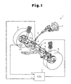
Fig. 1 is a perspective view schematically showing an electric power steering apparatus (EPS); -
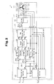
Fig. 2 is a block diagram representing the electric configuration of the EPS; -
Fig. 3 is a flowchart representing a procedure for detecting a phase with a failed electric current flow; -
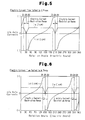
Fig. 4 is a graph representing changes of d/q axis currents in two-phase drive operation (when the electric current flow in the U phase has failed); -
Fig. 5 is a graph representing changes of the d/q axis currents in the two-phase drive operation (when the electric current flow in the V phase has failed); -
Fig. 6 is a graph representing changes of the d/q axis currents in the two-phase drive operation (when the electric current flow in the W phase has failed); -
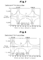
Fig. 7 is a graph representing changes of phase currents in two-phase drive operation (when the electric current flow in the U phase has failed); -
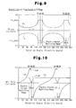
Fig. 8 is a graph representing changes of the phase currents in the two-phase drive operation (when the electric current flow in the V phase has failed); -
Fig. 9 is a graph representing changes of the phase currents in the two-phase drive operation (when the electric current flow in the W phase has failed); -
Fig. 10 is a graph representing changes of d/q axis currents in the current feedback control performed with a d-axis current command value Id* and a q-axis current command value Iq* maintained constant in electric current restriction ranges, when the electric current flow has failed (in the U phase); -
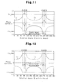
Fig. 11 is a graph representing changes of the phase currents in the current feedback control using the d-axis electric command value for when the electric current flow in the U phase fails, despite that there is no such failure of the electric current flow; -
Fig. 12 is a graph representing changes of the phase currents in the current feedback control performed with the d-axis current command value Id* and the q-axis current command value Iq* maintained constant in the electric current restriction ranges, when the electric current flow (in the U phase) has failed; -
Fig. 13 is a flowchart representing a procedure for determining whether there is an anomaly and switching control modes; -
Fig. 14 is a flowchart representing a procedure for calculating the d-axis current command value Id* and the q-axis current command value Iq* in the electric current restriction ranges; -
Fig. 15 is a graph illustrating conventional two-phase drive operation in which two phases other than a phase with a failed electric current flow are used as electric current flowing phases; and -
Fig. 16 is a graph representing changes of a d-axis current and a q-axis current in the conventional two-phase drive operation. - An embodiment of the present invention, which is an electric power steering apparatus (an EPS), will now be described with reference to the attached drawings.
- As shown in
Fig. 1 , a steering wheel 2 is fixed to asteering shaft 3. Thesteering shaft 3 is connected to arack 5 through a rack-and-pinion mechanism 4. Thesteering shaft 3 is rotated through steering. The rotation of thesteering shaft 3 is converted into linear reciprocation of therack 5 through the rack-and-pinion mechanism 4. This changes steering angles ofsteering wheels 6. - An
EPS 1 has anEPS actuator 10 and anECU 11. TheEPS actuator 10 is a steering force assisting device that applies assist force to a steering system in order to assist steering. TheECU 11 is control means that controls operation of theEPS actuator 10. - The
EPS actuator 10 is a rack type EPS actuator and is powered by amotor 12, or a drive source, which is arranged coaxially with therack 5. In theEPS actuator 10, themotor 12 generates assist torque, which is transmitted to therack 5 through a ball screw mechanism (not shown). Themotor 12 is a brushless type and driven by three-phase (U, V, and W phases) drive power supplied from theECU 11. TheECU 11 as a motor controller adjusts the assist force applied to the steering system by regulating the assist torque produced by the motor 12 (power assist control). - A
torque sensor 14 and avehicle speed sensor 15 are connected to theECU 11. The ECU 11 operates theEPS actuator 10, or carries out the power assist control, based on a steering torque τ and a vehicle speed V, which are detected by thetorque sensor 14 and thevehicle speed sensor 15, respectively. - The electrical configuration of the
EPS 1 according to the illustrated embodiment will hereafter be explained. - As illustrated in
Fig. 2 , the ECU 11 has amicrocomputer 17 and adriver circuit 18. Themicrocomputer 17 is signal output means that outputs a motor control signal. Thedriver circuit 18 supplies the three-phase power to themotor 12 based on the motor control signal. - The
driver circuit 18 is a publicly known PWM inverter that is configured by connecting three basic units (arms) corresponding to the respective phases in parallel. Each of the basic units is formed by a pair of switching elements that are connected in series. The motor control signal, which is output by themicrocomputer 17, defines ON duty ratio of each of the switching elements, which form thedriver circuit 18. When the motor control signal is provided to the gate terminal of each switching element, the switching element is turned selectively on and off in response to the motor control signal. This converts DC voltage of a power source (not shown) mounted in the vehicle to the three-phase (U, V, and W phases) drive power. The drive power is then supplied to themotor 12. - The
ECU 11 has electriccurrent sensors 21u, 21v, and 21w, which detect phase current values Iu, Iv, and Iw, respectively, and a rotation angle sensor 22 detecting a rotation angle θ of themotor 12. Based on the phase current values Iu, Iv, Iw and the rotation angle θ of themotor 12, which are detected based on detection signals of these sensors, and the steering torque τ and the vehicle speed V, themicrocomputer 17 outputs the motor control signal to thedriver circuit 18. - The
microcomputer 17 includes a calculatingsection 23 serving a calculating means and asignal generating section 24 serving as signal generating means. The calculatingsection 23 calculates an electric current command value as a target control amount of the assist force applied to the steering system. Thesignal generating section 24 generates the motor control signal based on the electric current command value, which is provided by the calculatingsection 23. - The calculating
section 23 calculates a d-axis current command value Id* and a q-axis current command value Iq* based on the steering torque τ and the vehicle speed V, which are detected by thetorque sensor 14 and thevehicle speed sensor 15, respectively. The calculatingsection 23 then outputs the obtained d-axis current command value Id* and q-axis current command value Iq* to thesignal generating section 24. Along with the d-axis current command value Id* and the q-axis current command value Iq*, which are provided by the calculatingsection 23, thesignal generating section 24 receives the phase current values Iu, Iv, Iw detected by the corresponding electriccurrent sensors 21u, 21v, 21w and the rotation angle θ detected by the rotation angle sensor 22. Based on the phase current values Iu, Iv, Iw and the rotation angle θ (the electric angle), thesignal generating section 24 generates the motor control signal by performing feedback control on electric currents in the d-q coordinate system. - Specifically, in the
signal generating section 24, the phase current values Iu, Iv, Iw are input to the first convertingsection 25 serving as a three phase/two phase converting section, together with the rotation angle θ. The first convertingsection 25 converts the phase current values Iu, Iv, Iw into a d-axis current value Id and a q-axis current value Iq of a d/q coordinate system. A d-axis current command value Id* and a q-axis current command value Iq*, which are output by the calculatingsection 23, are input to asubtractor 26d and a subtractor 26q, respectively, together with the corresponding one of the d-axis current value Id and the q-axis current value Iq. In normal control, the calculatingsection 23 outputs "0" as the d-axis current command value Id* (Id* = 0). - A d-axis current deviation ΔId, which is calculated by the
subtractor 26d, is sent to a F/B control section 27d. Also, a q-axis current deviation ΔIq, which is obtained by the subtractor 26q, is input to a F/B control section 27q. The F/B control section 27d performs feedback control for causing the d-axis current value Id, which represents the actual electric current, to follow the the d-axis current command value Id* output from the calculatingsection 23. Similarly, the F/B control section 27q carries out feedback control for causing the q-axis current value Iq, which represents the actual electric current, to follow the q-axis current command value Iq* output from the calculatingsection 23. - Specifically, the F/
B control section 27d obtains a d-axis voltage command value Vd* by multiplying the d-axis current deviation ΔId by a predetermined F/B gain (PI gain). The F/B control section 27q determines a q-axis voltage command value Vq* by multiplying the q-axis current deviation ΔIq by a predetermined F/B gain (PI gain). The d-axis voltage command value Vd* and the q-axis voltage command value Vq*, which are provided by the F/B control section 27d and the F/B control section 27q, respectively, are input to a second convertingsection 28, which is a two phase/threephase converting section 28, along with the rotation angle θ. The second convertingsection 28 converts the d-axis and q-axis voltage command values Vd*, Vq* into three phase voltage command values Vu*, Vv*, Vw*. - The voltage command values Vu*, Vv*, Vw* are input to a
PWM converting section 29. ThePWM converting section 29 generates duty command values αu, αv, αw corresponding to the voltage command values Vu*, Vv*, Vw*. Thesignal generating section 24 produces a motor control signal having an ON duty ratio represented by each of the duty command values αu, αv, αw. Themicrocomputer 17 outputs the motor control signal to (the gate terminals of) the switching terminals forming thedriver circuit 18. In this manner, themicrocomputer 17 controls operation of thedriver circuit 18, or supply of drive power to themotor 12. - As illustrated in
Fig. 2 , themicrocomputer 17 of theECU 11 has a determiningsection 31 that identifies the type of an anomaly if any anomaly occurs in theEPS 1. The ECU 11 (the microcomputer 17) changes control modes of themotor 12 in correspondence with the type of the anomaly identified by the determiningsection 31. - Specifically, the determining
section 31 receives an anomaly signal S_tr for detecting an anomaly in the mechanical structure of theEPS actuator 10. In response to the anomaly signal S_tr, the determiningsection 31 detects an anomaly in the mechanical system of theEPS 1. The determiningsection 31 also receives the q-axis current command value Iq*, the q-axis current value Iq, the phase current values Iu, Iv, Iw, and the rotation angular velocity ω of themotor 12 and the duty command values αu, αv, αw of the respective phases. Based on the respective condition amounts, the determiningsection 31 detects the occurrence of an anomaly in the control system. - More specifically, the determining
section 31 monitors the q-axis current deviation ΔIq in order to detect occurrence of an anomaly in the control system as a whole, including a failure of thetorque sensor 14 and that of thedriver circuit 18. In other words, the determiningsection 31 compares the q-axis current deviation ΔIq with a predetermined threshold value. If the q-axis current deviation ΔIq remains greater than or equal to the threshold value for longer than a predetermined time, the determiningsection 31 determines that an anomaly has occurred in the control system. - The determining
section 31 also detects a phase with a failed electric current flow caused by a break of a power line (including a motor coil) or a failed contact of thedriver circuit 18 based on the phase current values Iu, Iv, Iw, the rotation angular velocity w, and the duty command values αu, αv, αw of the respective phases. Such detection is carried out depending on whether a duty command value αx corresponding to an X phase is continuously outside a predetermined range (αLo ≤ α ≤ αHi) when a phase current value Ix of the X phase (X = U, V, W) is smaller than or equal to a predetermined value Ith (|Ix| ≤ Ith) and the rotation angular velocity ω is within a target range (|ω| ≤ ω0), in which it is determined whether a break has occurred. The predetermined range (αLo ≤ α ≤ αHi) is set as a range of values corresponding to the threshold value ω0 in accordance with which the value Ith and the target range are defined. - In this case, the value Ith, or the threshold value of the phase current value Ix, is set to a value near "0". The threshold value ω0 of the rotation angular velocity ω is set to a value corresponding to the base speed (the maximum rotation number) of the motor. The threshold values αLo and αHi of the duty command value αx are set to a value smaller than the lower limit value and a value greater than the upper limit value of the duty command value αx in normal control, respectively.
- Specifically, with reference to the flowchart of
Fig. 3 , the determiningsection 31 determines whether the absolute value of the detected phase current value Ix is smaller than or equal to the value Ith (step 101). If the absolute value of the phase current value Ix is smaller than or equal to the value Ith (|Ix| ≤ Ith, step 101: YES), the determiningsection 31 determines whether the absolute value of the rotation angular velocity ω is smaller than or equal to the predetermined threshold value ω0 (step 102). If the rotation angular velocity ω is smaller than or equal to the threshold value ω0 (|ω| ≤ ω0, step 102), the determiningsection 31 determines whether the duty command value αx is in the predetermined range (αLo ≤ αx ≤ αHi, step 103). If the duty command value αx is outside the predetermined range (step 103: NO), the determiningsection 31 determines that the electric current flow has failed in the X phase (step 104). - If the phase current value Ix is greater than the value Ith (|Ix| > Ith, step 101: NO), the rotation angular velocity ω is greater than the threshold value ω0 (|ω| > ω0, step 102: NO), or the duty command value αx is in the aforementioned predetermined range (αLo ≤ αx ≤ αHi, step 103: YES), the determining
section 31 determines that the X phase is free from a failure of electric current flow (normal functioning of the X phase determined, step 105). - That is, if a failure of electric current flow (a break) has occurred in the X phase (any one of the U, V, and W phases), the phase current value Ix of the X phase becomes "0". The phase current value Ix may become "0" or "a value near 0" in the following two cases other than the case of the break.
- The rotation angular velocity of the motor reaches the base speed (the maximum rotation number).
- The electric current command value is substantially "0".
- Accordingly, the determining
section 31 first compares the phase current value Ix of the X phase, which is an object of determination, with the predetermined value Ith so as to determine whether the phase current value Ix is "0". Then, the determiningsection 31 determines whether the current case corresponds to either one of the aforementioned two cases other than the case of the break, in which the phase current value Ix becomes "0" or "near 0". If the current case does not correspond to either one of the cases, the determiningsection 31 determines that there is a break in the X phase. - Specifically, if the duty command value αx is at an extreme level despite that the phase current value Ix is not as small as a value smaller than or equal to the value Ith, which is near zero, the determining
section 31 determines that a failure of electric current flow has occurred in the X phase. In the illustrated embodiment, the determiningsection 31 identifies the phase in which the failure of electric current flow has occurred by carrying out the above-described determination for the respective ones of the U, V, and W phases. - Although omitted from the flowchart of
Fig. 3 for the illustrative purposes, the determiningsection 31 carries out such determination only when the voltage of the power source is greater than or equal to a specified voltage necessary for driving themotor 12. The determiningsection 31 eventually determines that an anomaly has been detected depending on whether determination that the failure of electric current flow has occurred lasts a predetermined period of time in aprescribed step 104. - The ECU 11 (the microcomputer 17) switches the control modes of the
motor 12 in accordance with the result of determination by the determiningsection 31. Specifically, the determiningsection 31 outputs the result of the determination including detection of the failure of electric current flow as an anomaly detection signal S_tm. Then, the calculatingsection 23 calculates the electric current command values corresponding to the anomaly detection signal S_tm, and thesignal generating section 24 generates a motor control signal. In this manner, themicrocomputer 17 switches the control modes of themotor 12 from one to another. - More specifically, the
ECU 11 has three control modes. The control modes are a "normal control mode" for a normal state, an "assist suspension mode" for when an anomaly has been caused and thus themotor 12 must be stopped, and a "two-phase drive mode" for when a failure of electric current flow has occurred in any one of the phases of themotor 12. If the anomaly detection signal S_tm corresponds to the "normal control mode", the calculatingsection 23 calculates the d-axis current command value Id* and the q-axis current command value Iq* for the normal state. Thesignal generating section 24 generates the motor control signal correspondingly. - If the anomaly detection signal S_tm corresponds to the "assist suspension mode", the calculating
section 23 calculates the d-axis current command value Id* and the q-axis current command value Iq* and thesignal generating section 24 generates the motor control signal in such a manner as to stop themotor 12. The "assist suspension mode" is selected if an anomaly occurs in the mechanical system or thetorque sensor 14 or if an anomaly such as generation of an overcurrent is caused in the power supply system. Further, in accordance with the "assist suspension mode", themotor 12 may be stopped immediately or after the assist force is gradually decreased by reducing the output of themotor 12. In the latter case, the calculatingsection 23 gradually decreases the absolute value of the q-axis current command value Iq*. After themotor 12 is deactivated, themicrocomputer 17 switches the switching elements forming thedriver circuit 18 to the open state and opens a non-illustrated power source relay. - The anomaly detection signal S_tm corresponding to the "two-phase drive mode" carries information that identifies the phase in which the failure of electric current flow occurred. If the anomaly detection signal S_tm corresponds to the "two-phase drive mode", the
signal generating section 24 generates a motor control signal instructing to use, as electric current flowing phases, the two phases other than the phase with the failed electric current flow. - In the "two-phase drive mode", the calculating
section 23 calculates the d-axis current command value Id* using the following expressions (1) to (3), in correspondence with the detected phase with the failed electric current flow: - When the electric current flow fails in the U phase:

- When the electric current flow fails in the V phase:

- When the electric current flow fails in the W phase:

- With reference to
Figs. 4 to 6 , the d-axis current command value Id* is monotonically nondecreasing (when Iq* > 0) or monotonically nonincreasing (when Iq* < 0) with predetermined rotation angles θA, θB as asymptotic lines, in correspondence with the sign of the q-axis current command value Iq*. More specifically, the d-axis current command value Id* changes along a tangent curve (tangent: tanθ), or a tangent curve. - To facilitate the following explanation, in the range of the electric angles from 0° to 360°, the smaller one of the two rotation angles corresponding to the asymptotic lines will be referred to as the rotation angle θA and the greater one will be referred to as the rotation angle θB. As illustrated in
Fig. 4 , when an anomaly has occurred in the U phase and thus electric currents are introduced into the other two phases, which are the V and W phases, the rotation angle θA and the rotation angle θB are "90°" and "270°", respectively. With reference toFig. 5 , when the electric current flow in the V phase has failed, the rotation angle θA is "30°" and the rotation angle θB is "210°". With reference toFig. 6 , when the electric current flow in the W phase has failed, the rotation angle θA is "150°" and the rotation angle θB is "330°". - In calculation of the d-axis current command value Id* using the above-described expressions (1) to (3), the q-axis current command value Iq* is the same value as the q-axis current command value Iq* for the normal state, or an original value "Iq_as*" corresponding to the target value of the motor torque.
- Based on the d-axis current command value Id* and the q-axis current command value Iq*, the
signal generating section 24 performs current feedback control in the d/q coordinate system. In this manner, thesignal generating section 24 generates a motor control signal for carrying out two-phase drive operation control using the two phases other than the phase with the failed electric current flow as the electric current flowing phases. - That is, in the two-phase drive operation, the
signal generating section 24 performs the current feedback control based on the d-axis current command value Id*, which changes in accordance with the tangent curve determined by the expressions (1) to (3). In this manner, as represented by the following expressions (4) to (9), a phase current changing in accordance with a secant curve or a cosecant curve with the rotation angles θA, θB as the asymptotic lines is generated in each one of the U, V, and W phases (seeFigs. 7 to 9 ). The phase current value of the phase with the failed electric current is "0". The secant curve corresponds to the inverse number of sinθ (cosecant: cosecθ) and the cosecant curve corresponds to the inverse number of cosθ (secant: secθ). - When the electric current flow fails in the U phase:


- When the electric current flow fails in the V phase:


- When the electric current flow fails in the W phase:


- As a result, theoretically, the q-axis current value Iq that follow the q-axis current command value Iq* is generated in the d/q coordinate system, except for the values corresponding to the rotation angles θA, θB.
- In other words, if the rotation angle θ of the
motor 12 is not the rotation angles θA, θB, the q-axis current value Iq corresponding to the requested torque can be produced theoretically. That is, the q-axis current value Iq is generated as a value equal to the q-axis current command value Iq*, which is the target value of the motor torque. In this manner, generation of a torque ripple caused by two-phase drive operation is suppressed in such operation. Further, while maintaining improved steering comfort, assist force is continuously applied. - A maximum value Ix_max is set for the absolute values of the electric currents flowable in the
motor coils - Thus, in the two-phase drive operation, the calculating
section 23 calculates the d-axis current command value Id* and the q-axis current command value Iq* in such a manner that the phase current values of the two phases functioning as the electric current flowing phases become smaller than or equal to an upper limit value (Ix_max) and greater than or equal to a lower limit value (-Ix_max). This ensures maximum output performance of the motor and suppresses heating of the switching elements of the driver circuit or the motor coils of the phases caused by an electric current flow exceeding the maximum value Ix_max. The motor is thus stably operated. - Specifically, if current feedback control is carried out based on the d-axis current command value Id* changing along a tangent curve throughout the entire range of the rotation angles, the calculating
section 23 first determines whether the detected rotation angle θ of themotor 12 is in the range of the rotation angles in which a phase current exceeding the maximum value Ix_max is generated in the electric current flowing phases. - More specifically, the range of the rotation angles in which the value of the electric current flowing in each of the phases must be restricted is the ranges (Ix ≥ Ix_max, Ix ≤ -Ix_max) in which the phase current value becomes greater than or equal to the maximum value Ix_max. In other words, an electric current restriction range is the rotation angle range of the rotation angle θ1 to the rotation angle θ2 near the rotation angle θA corresponding to one of the asymptotic lines or the rotation angle range of the rotation angle θ3 to the rotation angle θ4 near the rotation angle θB corresponding to the other one of the asymptotic lines. Thus, by substituting the upper limit value (+Ix_max) and the lower limit value (-Ix_max) corresponding to the maximum value Ix_max into the above-described expressions (4) to (9) so as to obtain the solutions of the rotation angle θ, the four rotation angles θ1, θ2, θ3, θ4, which define the electric current restriction ranges, are identified.
- That is, if the phase with the failed electric current flow is the U phase (when the electric current flow in the U phase has failed), calculation is performed using the expressions (10), (11), (12), and (13), each obtained by substituting the upper limit value and the lower limit value of the phase current value into the above-described expression (4). In this manner, one of the rotation angles θA, θB corresponding to the asymptotic lines is determined. In other words, the rotation angles θ1, θ2 defining the electric current restriction range in the proximity of the rotation angle θA are obtained.
- When the electric current flow fails in the U phase:


- The solutions of the expressions (10) to (13), or the rotation angles θ1, θ2, are represented by the inverse function of cosθ (arc cosine). Thus, the following equations are satisfied: cos(-θ) = cosθ; cos(θ + 2n) = cosθ. Accordingly, using the following expressions (14) and (15), the other one of the predetermined rotation angles, the phase of which is offset from the phase of the rotation angle θA by 2n, is calculated. That is, the rotation angles θ3, θ4, which define the electric current restriction range in the proximity of the rotation angle θB, are obtained.


- Similarly, if the phase with the failed electric current flow is the V phase (when the electric current flow in the V phase has failed), calculation is performed using the expressions (16), (17), (18), and (19), each obtained by substituting the upper limit value and the lower limit value of the phase current value into the above-described expression (6). In this manner, one of the rotation angles θA, θB corresponding to the asymptotic lines, which is the rotation angles θ1, θ2 defining the electric current restriction range in the proximity of the rotation angle θA, is obtained.
- When the electric current flow fails in the V phase:


- The solutions of the expressions (16) to (19), or the rotation angles θ1, θ2, are represented by the inverse function of sinθ (arc sine). Thus, based on the equation sin(n - θ) = sinθ, the following expressions (20) and (21) are satisfied for the relationship between the rotation angles θ1, θ2 defining the electric current restriction range in the proximity of the rotation angle θA and the other predetermined rotation angle the phase of which is offset from the phase of the rotation angle θA by 2n, or the rotation angles θ3, θ4 defining the electric current restriction range in the proximity of the rotation angle θB. By performing calculation using the expressions (20), (21), the other rotation angles θ3, θ4 are determined.


- Further, if the phase with the failed electric current flow is the W phase (when the electric current flow in the W phase has failed), calculation is performed using the expressions (22), (23), (24), and (25), each obtained by substituting the upper limit value and the lower limit value of the phase current value into the above-described expression (9). In this manner, one of the rotation angles θA, θB corresponding to the asymptotic lines, which is the rotation angles θ3, θ4 defining the electric current restriction range in the proximity of the rotation angle θB, is obtained.
- When the electric current flow fails in the W phase:


- The solutions of the expressions (23) to (25), or the rotation angles θ3, θ4, are represented by the inverse function of sinθ (arc sine). Thus, based on the equation sin(n - θ) = sinθ, the following expressions (26) and (27) are satisfied for the relationship between the rotation angles θ3, θ4 defining the electric current restriction range in the proximity of the rotation angle θB and the other predetermined rotation angle the phase of which is offset from the phase of the rotation angle θB by 2n, or the rotation angles θ1, θ2 defining the electric current restriction range in the proximity of the rotation angle θA.


- Through calculation using the expressions (26) and (27), the other rotation angles θ1, θ2 are determined.
- In this manner, the determining
section 31 computes the rotation angles θ1, θ2, θ3, θ4, which define the corresponding electric current restriction ranges in the proximities of the predetermined rotation angles θA, θB corresponding to the two asymptotic lines. If the detected rotation angle θ of themotor 12 falls in either one of the electric current restriction ranges (θ1 < θ < θ2, θ3 < θ < θ4), the determiningsection 31 determines the d-axis current command value Id* and the q-axis current command value Iq* in such a manner that the phase current values of the electric current flowing phases become constant at the upper limit value (Ix_max) or the lower limit value (-Ix_max). - Specifically, the determining
section 31 calculates the d-axis current command value Id* and the q-axis current command value Iq* in correspondence with the identified phase with the failed electric current flow and the sign of the q-axis current command value Iq*, using the following expressions (28) to (51). - When the electric current flow fails in the U phase:
if θ1<θ<π/2 or 3π/2<θ<θ4


- When the electric current flow fails in the V phase:
if θ1<θ<π/6 or 7π/6<θ<θ4


- When the electric current flow fails in the W phase:
if θ1<θ<5π/6 or 11π/6<θ<θ4


- In this manner, while ensuring the maximum motor output performance and stable and continuous control of the motor, an anomaly in the control system is detected with improved accuracy.
- Specifically, with reference to
Fig. 10 , simply through the current feedback control with the d-axis current command value Id* and the q-axis current command value Iq* maintained constant in the respective electric current restriction ranges (θ1 < θ < θ2, θ3 < θ < θ4), the d-axis current Id does not follow the d-axis current command value Id*.Fig. 10 illustrates an example when the electric current flow in the U phase has failed. In other words, in a normal state (when normal electric current flows are ensured in the respective phases), the phase currents flow in the phases of the motor as illustrated inFig. 11 . The d-axis current value Id thus follows the d-axis current command value Id*. Contrastingly, if the electric current flow in any one of the phases fails and the two-phase drive operation is performed, the electric current value of the phase with the failed electric current flow becomes "0". In this state, the phase current values of the electric current flowing phases represent the waveforms illustrated inFig. 12 . As a result, the d-axis current value Id does not follow the d-axis current command value Id*. The output of themotor 12 thus cannot be maximized. - However, by carrying out the current feedback control based on the d-axis current command value Id* and the q-axis current command value Iq* determined by the expressions (28) to (51), the d-axis current value Id and the q-axis current value Iq become values that follow the d-axis current command value Id* and q-axis current command value Iq*, respectively, in the above-descried electric current restriction ranges. That is, the phase current values of the electric current flowing phases in the electric current restriction ranges become constant at the upper limit value (Ix_max) or the lower limit value (-Ix_max). This ensures the maximum output performance of the motor.
- Further, by determining in advance the q-axis current command value Iq* in such a range that the q-axis current value Id is capable of following a value corresponding to the q-axis current command value Iq*, reliability of anomaly detection based on the q-axis current deviation ΔIq is ensured in the electric current restriction ranges. As a result, in the two-phase drive operation, the anomaly detection in the control system is carried out with enhanced accuracy.
- Next, a procedure for performing the above-described anomaly detection and switching the control modes using the microcomputer will be explained, along with a procedure for generating a motor control signal.
- With reference to the flowchart of
Fig. 13 , themicrocomputer 17 first determines whether any anomaly has occurred (step 201). If it is determined that an anomaly has occurred (step 201: YES), themicrocomputer 17 determines whether the anomaly has occurred in the control system (step 202). If it is determined that the anomaly is in the control system (step 202: YES), themicrocomputer 17 determines whether the current control mode is the two-phase drive mode (step 203). If the current control mode is not the two-phase drive mode (step 203: NO), themicrocomputer 17 determines whether the anomaly of the control system corresponds to a failure of an electric current flow in any one of the phases (step 204). If it is determined that the failure of the electric current flow has occurred in any one of the phase (step 204: YES), themicrocomputer 17 outputs a motor control signal instructing to use the other two of the phases other than the phase with the failed electric current flow as the electric current flowing phases (the two-phase drive mode, step 205). - In
step 205, as has been described, themicrocomputer 17 computes the d-axis current command value Id* and the q-axis current command value Iq* in correspondence with the identified phase with the failed electric current flow and depending on whether the detected rotation angle θ falls in either one of the electric current restriction ranges (θ1 < θ < θ2, θ3 < θ < θ4). - Specifically, as represented in the flowchart of
Fig. 14 , themicrocomputer 17 determines whether the detected rotation angle θ is in the electric current restriction range (step 301). If the rotation angle θ is outside the electric current restriction range (step 301: NO), themicrocomputer 17 calculates the d-axis current command value Id* using the expressions (1) to (3) (step 302). In this case, themicrocomputer 17 calculates the same value as the q-axis current command value Iq* for the normal state (when normal electric current flows are ensured in the phases), or the original value corresponding to the target value of the motor torque (Iq* = Iq_as*). - If the detected rotation angle θ falls in the electric current restriction range (step 301: YES), the
microcomputer 17 calculates the d-axis current command value Id* and the q-axis current command value Iq* using the expressions (28) to (51) (step 303). - Contrastingly, if it is determined that there is no anomaly in step 201 (step 201: NO), the
microcomputer 17 outputs the motor control signal for the normal state (Id* = 0, the normal control mode, step 206). If it is determined that the anomaly has occurred outside the control system (step 202: NO), that the current control mode is the two-phase drive mode (step 203: YES), or that the anomaly is other than a failure of an electric current flow in any one of the phases (step 204: NO), themicrocomputer 17 switches to the assist suspension mode (step 207). Themicrocomputer 17 then outputs a motor control signal instructing to stop the operation of themotor 12 and opens the power source relay. - The illustrated embodiment has the following advantages.
- If there is any phase with a failed electric current flow, the
microcomputer 17 calculates the d-axis current command value Id* that changes along a tangent curve with the predetermined rotation angles θA, θB as the asymptotic lines. Themicrocomputer 17 then performs the current feedback control based on the d-axis current command value Id* and thus continuously outputs the motor control signal using the two phases other than the phase with the failed electric current flow as the electric current flowing phases. In the two-phase drive operation, themicrocomputer 17 calculates the d-axis current command value Id* and the q-axis current command value Iq* in such a manner that the phase current values of the electric current flowing phases become constant at the maximum values set for the respective phases in the ranges of the rotation angles in which the phase current values are to be restricted in correspondence with the maximum values, or the electric current restriction ranges (θ1 < θ < θ2, θ3 < θ < θ4). - In this manner, except for the electric current restriction ranges (θ1 < θ < θ2, θ3 < θ < θ4) in the proximities of the predetermined rotation angles θA, θB corresponding to the asymptotic lines, the motor electric current (the q-axis current value Iq) corresponding to the requested torque (the q-axis current command value Iq*) is generated. As a result, even if the electric current flow in any one of the phases fails, generation of a torque ripple is suppressed. Thus, while maintaining improved steering comfort, the assist force is continuously applied. Further, by maintaining the phase current values of the electric current flowing phases constant at the upper limit value (Ix_max) or the lower limit value (-Ix_max) in the electric current restriction ranges, the maximum output performance of the motor is ensured. Also, by determining, in advance, the q-axis current command value Iq* that can be achieved by the q-axis current value Iq, reliability of the anomaly detection based on the q-axis current deviation ΔIq is ensured in the electric current restriction ranges. As a result, even in the two-phase drive operation, an anomaly in the control system is detected with enhanced accuracy.
- The illustrated embodiment may be modified in the following forms.
- Although the present invention is embodied as the electric power steering apparatus (EPS) in the illustrated embodiment, the invention may be embodied as a motor controller used for purposes other than use in the EPS.
- In the illustrated embodiment, the
ECU 11, or the motor controller, operates in accordance with the three modes, which are the "normal control mode", "the assist suspension mode", and the "two-phase drive mode". However, the control modes for when an anomaly occurs are not restricted to these three modes. That is, as long as the operation of the motor is controlled with two phases other than the phase with a failed electric current flow as electric current flowing phases, any suitable motor controller may be employed. Further, a method for detecting an anomaly other than the method of the illustrated embodiment may be used. - The d-axis current command value Id*, which is calculated in the two-phase drive operation, does not necessarily have to be exactly equal to the value obtained from the expressions (1) to (3). However, if the d-axis current command value Id* is determined using the expressions (1) to (3), the q-axis current value Iq is generated as a value maximally close to the q-axis current command value Iq*. The closer the generated value to the d-axis current command value Id*, which is determined by the expressions, the more pronounced the obtained effect becomes.
- In the illustrated embodiment, detection of an anomaly in the control system is performed based on the q-axis current deviation ΔIq according to the present invention. However, as long as such anomaly detection is carried out based on an electric current deviation of a d-q coordinate system, the detection may be performed based on the d-axis current deviation ΔId or a resultant vector deviation of the d/q coordinate system.
- When a failure of an electric current flow occurs in any one of phases, a
microcomputer 17 calculates a d-axis current command value Id* that changes along a tangent curve with predetermined rotation angles θA, θB as asymptotic lines. Themicrocomputer 17 continuously outputs a motor control signal using two phases other than the phase with the failed electric current as electric current flowing phases by performing current feedback control in correspondence with the d-axis current command value Id*. In such two-phase drive operation, themicrocomputer 17 calculates the d-axis current command value Id* and a q-axis current command value Iq* in such a manner that the phase current values of the electric current flowing phases become constant at respective maximum values of flowable electric currents, which are set for the phases, in rotation angle restriction ranges in which the phase current values need to be restricted in correspondence with the maximum values, or electric current restriction ranges (θ1 < θ < θ2, θ3 < θ < θ4).
Claims (2)
- A motor controller (11) comprising:
signal output means (17) that outputs a motor control signal; and
a driver circuit (18) that supplies a three-phase drive power to a motor (12) based on the motor control signal,
wherein the signal output means (17) includes calculating means (23) that calculates a d-axis current command value (Id*) and a q-axis current command value (Iq*) of a d/q coordinate system as electric current command values, signal generating means (24) that generates the motor control signal by performing current feedback control of the d/q coordinate system based on the d-axis current command value (Id*) and the q-axis current command value (Iq*), and anomaly detecting means (31) that is capable of detecting a failed electric current flow in any one of the phases (U, V, W) of the motor (12), and wherein, when a failed electric current flow is detected, the signal output means (17) outputs the motor control signal using two phases other than the phase with the failed electric current flow as electric current flowing phases,
the motor controller being characterized in that a maximum value (Ix max) of an electric current flowable in each of the phases (U, V, W) of the motor (12) is set for each of phase current values (Iu, Iv, Iw) of the motor (12),
wherein, when a failed electric current flow occurs, the calculating means (23) calculates the d-axis current command value (Id*) changing along a tangent curve with a predetermined rotation angle (θA, θB) corresponding to the phase with the failed electric current flow as an asymptotic line, and calculates the d-axis current command value (Id*) and the q-axis current command value (Iq*) in such a manner that the phase current value (Iu, Iv, Iw) of each of the electric current flowing phases becomes constant at the maximum value (Ix_max) in a rotating angle range (θ1-θ2, θ3-θ4) in which the phase current value (Iu, Iv, Iw) needs to be restricted based on the maximum value (Ix_max), wherein,
when a failed electric current flow occurs, the calculating means (23) calculates the d-axis current command value (Id*) in correspondence with the phase with the failed electric current flow using the following expressions:When the electric current flow fails in the U phase: When the electric current flow falls in the V phase:
 When the electric current flow fails in the W phase:
 (θ: rotation angle, Id* : d-axis current command value,Iq* : q-axis current command value), andwherein the calculating means (23) calculates the d-axis current command value (Id*) and the q-axis current command value (Iq*) in the rotation angle range (θ1-θ2, θ3-θ4) in which the phase currents (Iu, Iv, Iw) need be restricted, using the following expressions:When the electric current flow fails in the U Phase:if θ1<θ<π/2 or 3π/2<θ<θ4


 if π/2<θ<θ2 or θ3<θ<3π/2


 When the electric current flow fails in the V phase:if θ1<θ<π/6 or 7π/6<θ<θ4


 When the electric current flow fails in the W phase:if θ1<θ<5π/6 or 11π/6<θ<θ4provided that :


 (Id* : d-axis current command value, Iq* : q-axis current command value, Ix_max: maximum value of flowable electric current).
 - An electric power steering apparatus being characterized by the motor controller according to claim 1.
Applications Claiming Priority (1)
| Application Number | Priority Date | Filing Date | Title |
|---|---|---|---|
| JP2007147188A JP5056175B2 (en) | 2007-06-01 | 2007-06-01 | Motor control device and electric power steering device |
Publications (3)
| Publication Number | Publication Date |
|---|---|
| EP1997713A2 EP1997713A2 (en) | 2008-12-03 |
| EP1997713A3 EP1997713A3 (en) | 2010-04-21 |
| EP1997713B1 true EP1997713B1 (en) | 2011-08-31 |
Family
ID=39719147
Family Applications (1)
| Application Number | Title | Priority Date | Filing Date |
|---|---|---|---|
| EP08157183A Expired - Fee Related EP1997713B1 (en) | 2007-06-01 | 2008-05-29 | Motor controller and electric power steering apparatus |
Country Status (4)
| Country | Link |
|---|---|
| US (1) | US7782000B2 (en) |
| EP (1) | EP1997713B1 (en) |
| JP (1) | JP5056175B2 (en) |
| CN (1) | CN101314362B (en) |
Families Citing this family (23)
| Publication number | Priority date | Publication date | Assignee | Title |
|---|---|---|---|---|
| JP4876838B2 (en) * | 2006-10-12 | 2012-02-15 | 株式会社ジェイテクト | Motor control device |
| EP2015445B1 (en) * | 2007-06-20 | 2011-12-14 | Jtekt Corporation | Motor controller and electric power steering apparatus |
| JP5338544B2 (en) * | 2009-07-28 | 2013-11-13 | 株式会社ジェイテクト | Electric power steering device |
| DE102009045351A1 (en) * | 2009-10-06 | 2011-04-14 | Robert Bosch Gmbh | Method for operating a drive unit and drive unit |
| US8283881B2 (en) * | 2010-03-09 | 2012-10-09 | GM Global Technology Operations LLC | Methods, systems and apparatus for synchronous current regulation of a five-phase machine |
| JP5672936B2 (en) * | 2010-10-18 | 2015-02-18 | 株式会社ジェイテクト | Electric power steering device |
| JP5406226B2 (en) * | 2011-01-07 | 2014-02-05 | 本田技研工業株式会社 | Electric power steering device |
| DE102012200089A1 (en) | 2011-01-07 | 2012-07-12 | Honda Motor Co., Ltd. | Electric power steering device |
| JP5862135B2 (en) * | 2011-09-12 | 2016-02-16 | 株式会社ジェイテクト | Electric power steering device |
| JP5811402B2 (en) * | 2011-12-26 | 2015-11-11 | 株式会社ジェイテクト | Steering device |
| US9440671B2 (en) | 2012-09-20 | 2016-09-13 | Polaris Industries Inc. | Vehicle |
| CN104661903B (en) | 2012-09-20 | 2017-11-10 | 北极星工业有限公司 | Multifunctional vehicle |
| KR101532602B1 (en) * | 2013-11-29 | 2015-06-30 | 현대모비스 주식회사 | Method for motor error detecting of motor driven power steering |
| JP5929878B2 (en) * | 2013-12-06 | 2016-06-08 | 株式会社デンソー | Control device and shift-by-wire system using the same |
| JP6368588B2 (en) * | 2014-08-27 | 2018-08-01 | 日立オートモティブシステムズ株式会社 | Feedback control device, electric power steering device |
| JP6506844B2 (en) * | 2014-12-16 | 2019-04-24 | ビーワイディー カンパニー リミテッドByd Company Limited | Electric vehicle, active safety control system of electric vehicle, control method of active safety control system of electric vehicle, and motor controller |
| JP6483039B2 (en) * | 2016-01-26 | 2019-03-13 | 株式会社日立製作所 | Power converter |
| JP6662081B2 (en) * | 2016-02-17 | 2020-03-11 | 株式会社デンソー | Control device for three-phase rotating machine and electric power steering device |
| JP2017226305A (en) * | 2016-06-22 | 2017-12-28 | 本田技研工業株式会社 | Electric power steering device |
| CA3035307C (en) | 2016-09-02 | 2024-04-02 | Kongsberg Inc. | Techniques for limiting electrical current provided to a motor in an electric power steering system |
| WO2019102539A1 (en) * | 2017-11-22 | 2019-05-31 | 三菱電機株式会社 | Rotating electric machine control device and electric vehicle |
| US10793181B2 (en) | 2018-02-13 | 2020-10-06 | Polaris Industries Inc. | All-terrain vehicle |
| JP6950598B2 (en) * | 2018-03-15 | 2021-10-13 | トヨタ自動車株式会社 | Motor control device, motor control program and motor control method |
Family Cites Families (48)
| Publication number | Priority date | Publication date | Assignee | Title |
|---|---|---|---|---|
| US2107177A (en) * | 1934-11-01 | 1938-02-01 | Bell Telephone Labor Inc | Stranded conductor |
| US2106177A (en) * | 1936-12-15 | 1938-01-25 | Victor J Hultquist | Building unit |
| US2514536A (en) * | 1947-08-11 | 1950-07-11 | Clyde D Burney | Plant growing block for a decorative fence construction |
| US2513177A (en) * | 1947-09-15 | 1950-06-27 | Irwin Sue Urth | Roasting rack |
| US4697130A (en) * | 1985-01-31 | 1987-09-29 | Westinghouse Electric Corp. | Induction motor regenerative brake control apparatus and method |
| US5006967A (en) * | 1989-05-22 | 1991-04-09 | Gary Diamond | Self-illuminating glass block construction unit |
| EP0577980B1 (en) | 1992-06-10 | 1997-09-10 | Fuji Electric Co., Ltd. | Ac variable speed driving apparatus and electric vehicle using the same |
| JP3479730B2 (en) * | 1994-10-20 | 2003-12-15 | 光洋精工株式会社 | Electric power steering device |
| JP3362537B2 (en) * | 1994-12-27 | 2003-01-07 | 日産自動車株式会社 | Fail-safe control of drive motor for electric vehicles |
| US5565153A (en) * | 1995-03-14 | 1996-10-15 | Sartorius Ag | Process of making polyvinylidene fluoride membranes |
| DE19747638C1 (en) * | 1997-10-29 | 1999-07-01 | Zahnradfabrik Friedrichshafen | Electrically assisted power steering for motor vehicles |
| JP3168986B2 (en) * | 1998-05-28 | 2001-05-21 | トヨタ自動車株式会社 | Motor control device and control method |
| DE59914974D1 (en) * | 1998-09-24 | 2009-04-23 | Levitronix Llc | Permanent magnetically excited electrical rotary drive |
| JP4154101B2 (en) * | 1999-12-28 | 2008-09-24 | 株式会社ジェイテクト | Motor control device for electric power steering device |
| US7521216B2 (en) * | 1999-12-29 | 2009-04-21 | Verenium Corporation | Nitrilases and methods for making and using them |
| US6456946B1 (en) * | 2000-02-25 | 2002-09-24 | Motorola, Inc. | System and method for motor fault detection |
| USD443381S1 (en) * | 2000-04-12 | 2001-06-05 | Litex Industries, Inc. | Vanity bar light fixture |
| US6741060B2 (en) * | 2001-04-05 | 2004-05-25 | Delphi Technologies, Inc. | Method and system for controlling a permanent magnet machine during fault conditions |
| JP3600805B2 (en) * | 2001-07-11 | 2004-12-15 | 三菱電機株式会社 | Electric power steering apparatus and control method used when detecting abnormality |
| USD456548S1 (en) * | 2001-07-25 | 2002-04-30 | Ying-Jue Lee | Wall fixture mounting base |
| JP3480843B2 (en) * | 2001-09-04 | 2003-12-22 | 三菱電機株式会社 | Electric power steering control device and control method |
| WO2003032478A1 (en) * | 2001-09-25 | 2003-04-17 | Daikin Industries, Ltd. | Phase current detector |
| US6741030B2 (en) * | 2002-06-19 | 2004-05-25 | Osram Sylvania Inc. | Control of leachable mercury in fluorescent lamps |
| JP3849979B2 (en) * | 2002-07-02 | 2006-11-22 | 本田技研工業株式会社 | Electric power steering device |
| DE10360582B4 (en) * | 2002-12-20 | 2017-02-09 | Volkswagen Ag | Electromechanical steering of a motor vehicle |
| JP4033030B2 (en) * | 2003-04-21 | 2008-01-16 | 株式会社ジェイテクト | Electric power steering device |
| JP4039317B2 (en) * | 2003-06-12 | 2008-01-30 | 株式会社ジェイテクト | Electric power steering device |
| US7278241B2 (en) * | 2003-07-02 | 2007-10-09 | Wirawan Margaretha H | Window assembly |
| JP2005094873A (en) * | 2003-09-16 | 2005-04-07 | Nissan Motor Co Ltd | Controller for three-phase ac motor |
| US7474067B2 (en) * | 2003-10-07 | 2009-01-06 | Jtekt Corporation | Electric power steering system |
| JP4474896B2 (en) * | 2003-10-22 | 2010-06-09 | 株式会社ジェイテクト | Power steering device |
| JP4405788B2 (en) * | 2003-11-18 | 2010-01-27 | 日本精工株式会社 | Control device for electric power steering device |
| JP2005176477A (en) * | 2003-12-10 | 2005-06-30 | Favess Co Ltd | Motor controller and vehicular steering device using the same |
| CN100490302C (en) | 2004-03-19 | 2009-05-20 | 三菱电机株式会社 | Motor controller |
| US7414425B2 (en) * | 2004-05-10 | 2008-08-19 | Temic Automotive Of North America, Inc. | Damping control in a three-phase motor with a single current sensor |
| JP4755593B2 (en) * | 2004-06-29 | 2011-08-24 | Thk株式会社 | Abnormality detection method and motor control device |
| JP4422567B2 (en) * | 2004-06-30 | 2010-02-24 | 株式会社日立製作所 | Motor drive device, electric actuator, and electric power steering device |
| JP4539218B2 (en) * | 2004-08-02 | 2010-09-08 | 日本精工株式会社 | Electric power steering device |
| JP4319112B2 (en) * | 2004-08-27 | 2009-08-26 | 三菱電機株式会社 | Electric power steering device |
| JP4289458B2 (en) * | 2004-09-07 | 2009-07-01 | 三菱電機株式会社 | Electric power steering control device |
| US7005822B1 (en) | 2004-09-21 | 2006-02-28 | Motorola, Inc. | Torque ripple reduction for a voltage mode motor controller |
| WO2006057317A1 (en) * | 2004-11-24 | 2006-06-01 | Nsk Ltd. | Non-connection motor, its drive control device and mortorized power steering device using drive control device of non-connection motor |
| US7348756B2 (en) * | 2004-11-30 | 2008-03-25 | Honeywell International Inc. | Advanced current control method and apparatus for a motor drive system |
| JP4115457B2 (en) * | 2005-03-23 | 2008-07-09 | 三菱電機株式会社 | Electric power steering device |
| JP2006335252A (en) * | 2005-06-02 | 2006-12-14 | Jtekt Corp | Electric power steering device |
| US7193388B1 (en) * | 2006-02-02 | 2007-03-20 | Emerson Electric Co. | Offset PWM signals for multiphase motor |
| JP5070867B2 (en) | 2007-02-05 | 2012-11-14 | 株式会社ジェイテクト | Motor control device and electric power steering device |
| US8116945B2 (en) * | 2008-01-16 | 2012-02-14 | Jtekt Corporation | Electric power steering device |
-
2007
- 2007-06-01 JP JP2007147188A patent/JP5056175B2/en not_active Expired - Fee Related
-
2008
- 2008-05-28 US US12/128,304 patent/US7782000B2/en not_active Expired - Fee Related
- 2008-05-29 EP EP08157183A patent/EP1997713B1/en not_active Expired - Fee Related
- 2008-05-30 CN CN2008100983835A patent/CN101314362B/en not_active Expired - Fee Related
Also Published As
| Publication number | Publication date |
|---|---|
| CN101314362B (en) | 2012-11-14 |
| US20080297958A1 (en) | 2008-12-04 |
| EP1997713A2 (en) | 2008-12-03 |
| JP5056175B2 (en) | 2012-10-24 |
| CN101314362A (en) | 2008-12-03 |
| US7782000B2 (en) | 2010-08-24 |
| EP1997713A3 (en) | 2010-04-21 |
| JP2008301658A (en) | 2008-12-11 |
Similar Documents
| Publication | Publication Date | Title |
|---|---|---|
| EP1997713B1 (en) | Motor controller and electric power steering apparatus | |
| EP2003041B1 (en) | Motor controller and electric power steering apparatus | |
| US7813089B2 (en) | Motor controller and electric power steering apparatus | |
| US7859206B2 (en) | Motor controller and electric power steering apparatus | |
| US7813626B2 (en) | Motor controller and electric power steering apparatus | |
| EP2015445B1 (en) | Motor controller and electric power steering apparatus | |
| EP2062802B1 (en) | Electric power steering device | |
| EP2043252A1 (en) | Motor controller and electric power steering apparatus | |
| EP2080688B1 (en) | Electric power steering device | |
| EP2043256A2 (en) | Motor controller and electric power steering apparatus | |
| JP4918870B2 (en) | Motor control device and electric power steering device | |
| EP2567879B1 (en) | Electric power steering system | |
| JP5146133B2 (en) | Motor control device and electric power steering device | |
| JP5266793B2 (en) | Electric power steering device | |
| JP5315727B2 (en) | Electric power steering device | |
| JP2010137627A (en) | Electric power steering device | |
| JP5082608B2 (en) | Motor control device and electric power steering device | |
| JP5326264B2 (en) | Motor control device and electric power steering device |
Legal Events
| Date | Code | Title | Description |
|---|---|---|---|
| PUAI | Public reference made under article 153(3) epc to a published international application that has entered the european phase |
Free format text: ORIGINAL CODE: 0009012 |
|
| AK | Designated contracting states |
Kind code of ref document: A2 Designated state(s): AT BE BG CH CY CZ DE DK EE ES FI FR GB GR HR HU IE IS IT LI LT LU LV MC MT NL NO PL PT RO SE SI SK TR |
|
| AX | Request for extension of the european patent |
Extension state: AL BA MK RS |
|
| PUAL | Search report despatched |
Free format text: ORIGINAL CODE: 0009013 |
|
| AK | Designated contracting states |
Kind code of ref document: A3 Designated state(s): AT BE BG CH CY CZ DE DK EE ES FI FR GB GR HR HU IE IS IT LI LT LU LV MC MT NL NO PL PT RO SE SI SK TR |
|
| AX | Request for extension of the european patent |
Extension state: AL BA MK RS |
|
| RIC1 | Information provided on ipc code assigned before grant |
Ipc: H02P 21/00 20060101ALI20100318BHEP Ipc: B62D 5/04 20060101AFI20080908BHEP |
|
| 17P | Request for examination filed |
Effective date: 20101021 |
|
| AKX | Designation fees paid |
Designated state(s): DE FR |
|
| GRAP | Despatch of communication of intention to grant a patent |
Free format text: ORIGINAL CODE: EPIDOSNIGR1 |
|
| RIC1 | Information provided on ipc code assigned before grant |
Ipc: B62D 5/04 20060101AFI20110125BHEP Ipc: H02P 21/00 20060101ALI20110125BHEP |
|
| GRAS | Grant fee paid |
Free format text: ORIGINAL CODE: EPIDOSNIGR3 |
|
| GRAA | (expected) grant |
Free format text: ORIGINAL CODE: 0009210 |
|
| AK | Designated contracting states |
Kind code of ref document: B1 Designated state(s): DE FR |
|
| REG | Reference to a national code |
Ref country code: DE Ref legal event code: R096 Ref document number: 602008009239 Country of ref document: DE Effective date: 20111027 |
|
| PLBE | No opposition filed within time limit |
Free format text: ORIGINAL CODE: 0009261 |
|
| STAA | Information on the status of an ep patent application or granted ep patent |
Free format text: STATUS: NO OPPOSITION FILED WITHIN TIME LIMIT |
|
| 26N | No opposition filed |
Effective date: 20120601 |
|
| REG | Reference to a national code |
Ref country code: DE Ref legal event code: R097 Ref document number: 602008009239 Country of ref document: DE Effective date: 20120601 |
|
| REG | Reference to a national code |
Ref country code: FR Ref legal event code: PLFP Year of fee payment: 9 |
|
| REG | Reference to a national code |
Ref country code: FR Ref legal event code: PLFP Year of fee payment: 10 |
|
| REG | Reference to a national code |
Ref country code: FR Ref legal event code: PLFP Year of fee payment: 11 |
|
| PGFP | Annual fee paid to national office [announced via postgrant information from national office to epo] |
Ref country code: DE Payment date: 20210505 Year of fee payment: 14 Ref country code: FR Payment date: 20210412 Year of fee payment: 14 |
|
| REG | Reference to a national code |
Ref country code: DE Ref legal event code: R119 Ref document number: 602008009239 Country of ref document: DE |
|
| PG25 | Lapsed in a contracting state [announced via postgrant information from national office to epo] |
Ref country code: FR Free format text: LAPSE BECAUSE OF NON-PAYMENT OF DUE FEES Effective date: 20220531 |
|
| PG25 | Lapsed in a contracting state [announced via postgrant information from national office to epo] |
Ref country code: DE Free format text: LAPSE BECAUSE OF NON-PAYMENT OF DUE FEES Effective date: 20221201 |