EP1997636A1 - Nozzle plate for inkjet head, method for manufacturing the same, and treatment liquid for inkjet head - Google Patents
Nozzle plate for inkjet head, method for manufacturing the same, and treatment liquid for inkjet head Download PDFInfo
- Publication number
- EP1997636A1 EP1997636A1 EP08290004A EP08290004A EP1997636A1 EP 1997636 A1 EP1997636 A1 EP 1997636A1 EP 08290004 A EP08290004 A EP 08290004A EP 08290004 A EP08290004 A EP 08290004A EP 1997636 A1 EP1997636 A1 EP 1997636A1
- Authority
- EP
- European Patent Office
- Prior art keywords
- ink
- nozzle plate
- repellent layer
- inkjet head
- ink ejecting
- Prior art date
- Legal status (The legal status is an assumption and is not a legal conclusion. Google has not performed a legal analysis and makes no representation as to the accuracy of the status listed.)
- Granted
Links
Images


Classifications
-
- B—PERFORMING OPERATIONS; TRANSPORTING
- B41—PRINTING; LINING MACHINES; TYPEWRITERS; STAMPS
- B41J—TYPEWRITERS; SELECTIVE PRINTING MECHANISMS, i.e. MECHANISMS PRINTING OTHERWISE THAN FROM A FORME; CORRECTION OF TYPOGRAPHICAL ERRORS
- B41J2/00—Typewriters or selective printing mechanisms characterised by the printing or marking process for which they are designed
- B41J2/005—Typewriters or selective printing mechanisms characterised by the printing or marking process for which they are designed characterised by bringing liquid or particles selectively into contact with a printing material
- B41J2/01—Ink jet
- B41J2/135—Nozzles
-
- B—PERFORMING OPERATIONS; TRANSPORTING
- B41—PRINTING; LINING MACHINES; TYPEWRITERS; STAMPS
- B41J—TYPEWRITERS; SELECTIVE PRINTING MECHANISMS, i.e. MECHANISMS PRINTING OTHERWISE THAN FROM A FORME; CORRECTION OF TYPOGRAPHICAL ERRORS
- B41J2/00—Typewriters or selective printing mechanisms characterised by the printing or marking process for which they are designed
- B41J2/005—Typewriters or selective printing mechanisms characterised by the printing or marking process for which they are designed characterised by bringing liquid or particles selectively into contact with a printing material
- B41J2/01—Ink jet
- B41J2/135—Nozzles
- B41J2/14—Structure thereof only for on-demand ink jet heads
- B41J2/1433—Structure of nozzle plates
-
- B—PERFORMING OPERATIONS; TRANSPORTING
- B41—PRINTING; LINING MACHINES; TYPEWRITERS; STAMPS
- B41J—TYPEWRITERS; SELECTIVE PRINTING MECHANISMS, i.e. MECHANISMS PRINTING OTHERWISE THAN FROM A FORME; CORRECTION OF TYPOGRAPHICAL ERRORS
- B41J2/00—Typewriters or selective printing mechanisms characterised by the printing or marking process for which they are designed
- B41J2/005—Typewriters or selective printing mechanisms characterised by the printing or marking process for which they are designed characterised by bringing liquid or particles selectively into contact with a printing material
- B41J2/01—Ink jet
- B41J2/135—Nozzles
- B41J2/16—Production of nozzles
-
- B—PERFORMING OPERATIONS; TRANSPORTING
- B41—PRINTING; LINING MACHINES; TYPEWRITERS; STAMPS
- B41J—TYPEWRITERS; SELECTIVE PRINTING MECHANISMS, i.e. MECHANISMS PRINTING OTHERWISE THAN FROM A FORME; CORRECTION OF TYPOGRAPHICAL ERRORS
- B41J2/00—Typewriters or selective printing mechanisms characterised by the printing or marking process for which they are designed
- B41J2/005—Typewriters or selective printing mechanisms characterised by the printing or marking process for which they are designed characterised by bringing liquid or particles selectively into contact with a printing material
- B41J2/01—Ink jet
- B41J2/135—Nozzles
- B41J2/16—Production of nozzles
- B41J2/1606—Coating the nozzle area or the ink chamber
-
- B—PERFORMING OPERATIONS; TRANSPORTING
- B41—PRINTING; LINING MACHINES; TYPEWRITERS; STAMPS
- B41J—TYPEWRITERS; SELECTIVE PRINTING MECHANISMS, i.e. MECHANISMS PRINTING OTHERWISE THAN FROM A FORME; CORRECTION OF TYPOGRAPHICAL ERRORS
- B41J2/00—Typewriters or selective printing mechanisms characterised by the printing or marking process for which they are designed
- B41J2/005—Typewriters or selective printing mechanisms characterised by the printing or marking process for which they are designed characterised by bringing liquid or particles selectively into contact with a printing material
- B41J2/01—Ink jet
- B41J2/135—Nozzles
- B41J2/16—Production of nozzles
- B41J2/162—Manufacturing of the nozzle plates
-
- B—PERFORMING OPERATIONS; TRANSPORTING
- B41—PRINTING; LINING MACHINES; TYPEWRITERS; STAMPS
- B41J—TYPEWRITERS; SELECTIVE PRINTING MECHANISMS, i.e. MECHANISMS PRINTING OTHERWISE THAN FROM A FORME; CORRECTION OF TYPOGRAPHICAL ERRORS
- B41J2/00—Typewriters or selective printing mechanisms characterised by the printing or marking process for which they are designed
- B41J2/005—Typewriters or selective printing mechanisms characterised by the printing or marking process for which they are designed characterised by bringing liquid or particles selectively into contact with a printing material
- B41J2/01—Ink jet
- B41J2/135—Nozzles
- B41J2/16—Production of nozzles
- B41J2/1621—Manufacturing processes
- B41J2/1626—Manufacturing processes etching
- B41J2/1629—Manufacturing processes etching wet etching
-
- B—PERFORMING OPERATIONS; TRANSPORTING
- B41—PRINTING; LINING MACHINES; TYPEWRITERS; STAMPS
- B41J—TYPEWRITERS; SELECTIVE PRINTING MECHANISMS, i.e. MECHANISMS PRINTING OTHERWISE THAN FROM A FORME; CORRECTION OF TYPOGRAPHICAL ERRORS
- B41J2/00—Typewriters or selective printing mechanisms characterised by the printing or marking process for which they are designed
- B41J2/005—Typewriters or selective printing mechanisms characterised by the printing or marking process for which they are designed characterised by bringing liquid or particles selectively into contact with a printing material
- B41J2/01—Ink jet
- B41J2/135—Nozzles
- B41J2/16—Production of nozzles
- B41J2/1621—Manufacturing processes
- B41J2/1632—Manufacturing processes machining
Definitions
- the present invention relates to a nozzle plate for an inkjet head, a manufacturing method and a processing method of the same, and a treatment liquid used for manufacturing and processing the same.
- the inkjet head having the layer configuration as described in the aforementioned JP-A-2003-63014 has a problem that when the ink-repellent surface layer around the nozzles is damaged, the surface layer can be corroded and stripped, resulting in interference with the linear advancing property of ejected ink.
- a method for forming a cover plate around an ink ejecting hole of the nozzle plate JP-A-2005-7789 ) is provided to make the ink-repellent layer around the nozzles hardly damaged.
- the present invention has been made in consideration of the aforementioned problems and it is an object of the present invention to provide a nozzle plate for an inkjet head, a manufacturing method and a processing method of the same, and a treatment liquid used for manufacturing and processing the same which can solve the aforementioned problems. It is another object of the present invention to allow the process on demand at a customer's place.
- the present invention has the following arrangements.
- a nozzle plate for an inkjet head comprising a substrate and ink ejecting holes formed in the substrate, wherein an ink-repellent layer is formed on an ink ejecting side surface of the nozzle plate and portions around the ink ejecting holes of the ink-repellent layer are selectively removed so that portions around the ink ejecting holes of the nozzle plate are exposed.
- a method of producing a nozzle plate for an inkjet head comprising:
- a method of producing a nozzle plate for an inkjet head as described in Arrangement 2, wherein the step of selectively removing the portions around the ink ejecting holes of the ink-repellent layer comprises:
- a treatment liquid for an inkjet head which is used for processing a layer formed on a surface of a nozzle plate by co-precipitating a fluororesin with a metal, wherein the treatment liquid contains acidic liquid having a function of decreasing the mechanical strength of the layer formed by co-precipitating the fluororesin with the metal.
- the nozzle plate for an inkjet head can solve problems which occur when an ink-repellent layer exists around an ink ejecting hole, as will be described in detail below.
- portions around the ink ejecting holes (nozzle openings, nozzle orifices) of the ink-repellent layer can be selectively removed in an easy manner as will be described in detail below.
- an ink-repellent layer 2 is formed on a surface of an ink ejecting side of the nozzle plate 1 composed of a substrate having an ink ejecting hole 1a and a portion around the ink ejecting hole 1a of the ink-repellent layer 2 is selectively removed so that the portion around the ink ejecting hole of the nozzle plate (surface) is exposed.
- the present invention solves the following problems which occur when an ink-repellent layer exists around an ink ejecting hole. Specifically, case that an ink-repellent layer exists around the ink ejecting hole la as shown in Fig. 1 (2) (see JP-A-2003-63014 supra) has a structure to be easily damaged physically because an end face (edge) of the ink-repellent layer 2 is wiped by direct touching of a wiper, for example. The damage on the end face (edge) 2' of the ink repellent layer 2 results in interference with the linear advancing property of ejected ink.
- the corrosion on the end face (edge) of the ink-repellent layer impairs the linear advancing property. Since no ink-repellent layer 2 exists around the ink ejecting hole la in the present invention, there is no factor of impairing the linear advancing property of ejected ink mentioned above, thereby providing good print quality.
- FIG. 2 (1) and 2 (2) are schematic illustrations for explaining a situation that the ink ejecting hole of the nozzle plate in the inkjet head is filled with a treatment chemical for decreasing the mechanical strength of the ink-repellent layer.
- Fig. 2 (1) is a sectional view and Fig. 2 (2) is a perspective view.
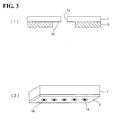
- Figs. 3(1) and 3(2) are illustrations for explaining a situation that the ink-repellent layer around the ink ejecting hole is selectively removed.
- Fig. 3(1) is a sectional view and Fig. 3(2) is a perspective view.
- a nozzle plate 1 comprising a flat plate-like substrate with ink ejecting holes 1a formed therein and having an ink-repellent layer 2 which is formed on an ink ejecting side thereof is prepared.
- the nozzle plate 1 is made of an alloy material containing, for example, Ni or Fe.
- the ink ejecting holes la are sometimes called nozzle openings, nozzle orifices.
- the ink-repellent layer 2 is formed on an end face, i.e. the outermost surface, of the inkjet head.
- step (1) and step (2) portions around the ink ejecting holes of the ink-repellent layer are selectively removed. This process is preferably conducted by the following step (1) and step (2).
- the step (1) is a step of selectively decreasing the mechanical strength of the ink-repellent layer 2 of portions around the ink ejecting holes la by filling the treatment chemical 3 into the ink ejecting holes la as shown in Figs. 2 (1) and 2 (2) .
- the nozzle plate 1 is horizontally held in a state that the ink ejecting side of the nozzle plate 1 faces downward and the treatment chemical 3 is poured into each ink ejecting hole la from above. Accordingly, as shown in Figs.
- the treatment chemical 3 projecting from the surface of the ink ejecting side of the nozzle plate 1 produces a droplet (liquid pool) 3a because of the function of the ink-repellent layer 2. Therefore, the treatment chemical 3 can function selectively on a portion around the ink ejecting hole la of the ink-repellent layer, thereby selectively decreasing the mechanical strength of the ink-repellent layer at the portion around the ink ejecting hole 1a, i.e. an area in certain radius about the center of the ink ejecting hole 1a.
- the step (2) is a step of selectively removing the portions about the ink ejecting holes of the ink-repellent layer of which the mechanical strength is selectively decreased.
- a blade 4 having flexibility is moved to slide on the ink-repellent layer 2 so as to rub the ink-repellent layer 2. Therefore, the portions around the ink ejecting holes of the ink-repellent layer 2 of which the mechanical strength is selectively decreased can be selectively removed. As a result, as shown in Figs.
- the portions around the ink ejecting holes la of the ink-repellent layer 2 are selectively (partially) removed so that the portions around the ink ejecting holes 1a of the nozzle plate (surface) 1b are exposed (becomes exposed surfaces). Since the ink-repellent layer 2 of the nozzle plate thus obtained does not exist on the portions around the ink ejecting holes 1a, ink deflection, that may occur in case of a nozzle plate having an ink-repellent layer also existing on portions around ink ejecting holes, does not occur, thereby obtaining excellent print quality.
- portions around the ink ejecting holes (nozzle openings, nozzle orifices) of the ink-repellent layer can be selectively removed in an easy manner as mentioned above.
- the removal can be easily conducted at a place without a production facility exclusively for processing the nozzle plate, by placing a head to an inkjet printer before being treated and then supplying the treatment chemical to ink ejecting holes. Therefore, the process on demand at a customer's place is allowed.
- the ink-repellent layer 2 is preferably a layer obtained by co-precipitating a fluororesin with a metal.
- the layer obtained by co-precipitating a fluororesin with a metal is formed, for example, by a composite plating method.
- the composite plating method is a plating method in which fine particles are entered and mixed in a plating bath and are co-precipitated with the metal simultaneously so as to apply a new function to a thus formed layer.
- the composite plating may be electrolytic plating or electroless plating.
- resins such as PTFE (polytetrafluoroethylene), polyperfluoroalkoxy butadiene, polyfluorovinylidene, polyfluorovinyl, polydiperfluoroalkyl fumarate, PFA (tetrafluoroethylene-perfluoroalkylvinylether copolymer), FEP (tetrafluoroethylene-hexafluoropropylene copolymer), ETFE (tetrafluoroethylene-ethylene copolymer), PVDF (polyvinylidene fluoride), and PCTFE (polychlorotrifluoroethylene) may be used singly or in mixture.
- PTFE polytetrafluoroethylene
- polyperfluoroalkoxy butadiene polyfluorovinylidene
- polyfluorovinyl polydiperfluoroalkyl fumarate
- PFA tetrafluoroethylene-perfluoroalkylvinylether copolymer
- fluororesins are capable of imparting ink repellency (water repellency).
- these fluororesins are stable relative to chemicals including acid, alkali, and/or organic solvent.
- FEP tetrafluoroethylene-hexafluoropropylene copolymer
- PTFE polytetrafluoroethylene
- nickel, copper, silver, tin, zinc and the like may be used.
- metal are materials having great surface hardness and excellent abrasion resistance such as nickel, nickel-cobalt alloy, and nickel-boron alloy.
- the treatment chemical 3 is preferably acidic liquid capable of gradually dissolving metal in the layer formed by co-precipitating the fluororesin with the metal. Accordingly, only the fluororesin remains after dissolving the metal by the acidic liquid so as to decrease the mechanical strength of the eutectoid layer of the fluororesin and the metal.
- the acidic liquid dissolves Ni so as to leave FEP only, thereby decreasing the mechanical strength of the ink-repellent layer.
- the acidic liquid is preferably aqueous solution of which pH is in a range from 1.5 to 4.0 and, more preferably, aqueous solution containing organic carboxylic acid.
- organic carboxylic acid hydroxycarboxylic acid (for example, glycolic acid), acetic acid, formic acid, and the like may be used.
- hydroxycarboxylic acid for example, glycolic acid
- acetic acid formic acid, and the like
- hydroxycarboxylic acid for example, glycolic acid
- Glycolic acid CH 2 (OH)COOH
- AHA alpha-hydroxy acids
- the wettability of the aforementioned acidic liquid is increased by adding penetrable surfactant into the acidic liquid. This is preferable because this imparts a function of promoting the dissolution of the portions around the nozzles of the ink-repellent layer 2.
- the blade 4 is preferably a blade which satisfies characteristics such as having flexibility, having a function of mechanically promoting the removal of the ink-repellent layer 2, not skinning the surface of the ink-repellent layer 2, and being made of material capable of bearing with acid, alkali, and the like.
- the blade 4 is preferably made of a rubber material.
- the material of the blade 4 is not limited to rubber material and may be any material satisfying the aforementioned characteristics.
- the sliding action as one action of the blade is preferably conducted by reciprocation because the reciprocation provides an effect that the dissolved portions of the ink-repellent layer 2 can be removed without remaining at peripheries.
- the sliding action is preferably conducted at certain intervals (periodically) because the periodical operation can reset variation in diameter and height among droplets 3a of the treatment chemical 3 (physically remove excess meniscus or the chemical around the nozzles) so as to adjust the diameters of removed portions, thereby homogenizing the diameters for respective nozzles.
- a head cleaning mechanism comprising a wiping mechanism for an inkjet head in an inkjet printer may be employed. Therefore, the process on demand can be facilitated without a special device.
- the concentration of glycolic acid in aqueous solution of glycolic acid is preferably in a range from 1 wt% to 10 wt%.
- the concentration lower than 1 wt% can not dissolve the metal to an extent as decreasing the mechanical strength of the ink-repellent layer 2 or takes too long time to dissolve the metal, while the concentration higher than 10 wt% makes the control for dissolution of the ink-repellent layer 2 difficult because of too high dissolving speed and may also dissolve the nozzle plate 1 below the ink-repellent layer if the dissolving effect is too strong.
- penetrable surfactant for example acetylenic surfactant (example: Surfynol 465 (available from Air Products and Chemicals, Inc.)) is added at a concentration of about 1 wt% to the treatment chemical 3. Since the addition of the penetrable surfactant increases the wettability, it is preferable because this imparts a function of promoting the dissolution of the portions around the nozzles of the ink-repellent layer 2.
- acetylenic surfactant either a nonionic surfactant, a cationic surfactant, or an anionic surfactant may be used.
- diethylene glycol is added at a concentration of 0-15 wt% to the treatment chemical 3 so as to slow the reaction speed, thereby facilitating the control of the dissolving time of the ink-repellent layer 2.
- the inkjet recording apparatus employed in the present invention may be an inkjet recording apparatus in which a piezoelectric element mechanically changes volume so as to form and eject ink droplets, i.e. so-called piezo head type inkjet recording apparatus, or an inkjet recording apparatus in which thermal energy is applied to ink composition to expand volume so as to form and eject ink droplets, i.e. so-called bubble jet type ("Bubble jet" is a registered trade name) or thermal jet type inkjet recording apparatus.
- the nozzle plate of the present invention is extremely advantageously used in an inkjet recording method using piezoelectric element. Since the piezo type inkjet recording head has excellent durability, the piezo type inkjet recording head is especially preferably used in a field that requires a prolonged stable ejection such as textile printing. The nozzle plate of the present invention extremely fits to the piezo type inkjet recording head so as to enable stable continuous ejection in a wide range of temperature. This is extremely suitable for textile printing on long media requiring huge quantities of ejection and this is a great advantage by the present invention.
- the material of the nozzle plate is not specially limited in the present invention
- the nozzle plate is preferably made of metal, ceramics, silicon, glass, or plastic and, more preferably, made of a metal such as titanium, chromium, iron, cobalt, nickel, copper, zinc, tin, and gold; an alloy such as nickel-phosphorus alloy, tin-copper-phosphorus alloy, copper-zinc alloy, and stainless steel; polycarbonate; polysulfone; acrylonitrile-butadiene- styrene copolymer; polyethylene terephthalate; or one of various photosensitive resins.
- a metal such as titanium, chromium, iron, cobalt, nickel, copper, zinc, tin, and gold
- an alloy such as nickel-phosphorus alloy, tin-copper-phosphorus alloy, copper-zinc alloy, and stainless steel
- polycarbonate polysulfone
- acrylonitrile-butadiene- styrene copolymer poly
- liquid having a function of dissolving or decomposing at least parts of components of the ink-repellent layer or liquid having a function of dissolving or decomposing the ink-repellent layer may be employed as the treatment chemical 3.
- the portion around each ink ejecting hole 1a of the ink-repellent layer as shown in Figs. 2 (1) and 2 (2)
- the portion around each ink ejecting hole 1a i.e. the area in certain radius about the center of each ink ejecting hole la of the ink-repellent layer can be selectively removed as shown in Figs. 3 (1) and 3 (2) .
- the treatment chemical 3 may be used as treatment liquid for an inkjet head without being entered in the ink ejecting holes, for example.
- the nozzle plate with the ink-repellent layer of which portions around the ink ejecting holes are removed as shown in Figs. 1 (1) , 3 (1) and 3 (2) can be obtained by masking the non-removed portion of the ink-repellent layer and then treating the ink-repellent layer with the aforementioned treatment chemical 3 or more powerful inorganic acid.
- this procedure requires the masking, so it requires complex steps.
- 1 (1) , 3 (1) and 3 (2) can be obtained by masking the non-removed portion of the ink-repellent layer and then treating the ink-repellent layer with plasma irradiation described in JP-A-2003-63014 supra. This procedure also requires the masking, so it is complex and further requires a plasma irradiation device.
- a nozzle plate for an inkjet head was processed by the following procedure.
- An ink-repellent layer 2 was formed on the surface of the nozzle plate as shown in Figs. 2 (1) and 2 (2) .
- the ink-repellent layer 2 was an electroless nickel/FEP (tetrafluoroethylene-hexafluoropropylene copolymer) composite plating layer formed by the electroless composite plating method.
- the inkjet head was filled with acidic treatment chemical in the same manner as normal filling of an inkjet head with ink.
- the composition and the pH of the acidic treatment chemical were as follows:
- Wiping operation was conducted 4-8 times periodically every two hours to selectively remove portions around ejecting outlets of the ink-repellent layer on the nozzle plate.
- Residues around the nozzles were removed by the cleaning operation with the cleaning liquid. It should be noted that the aforementioned steps (1) to (4) were conducted at a temperature of from 20 to 30 °C.
- the inkjet head had the nozzle plate in which portions around the ink ejecting holes of the ink-repellent layer were selectively removed as shown in Figs. 3 (1) and 3 (2) .
- the inkjet head of the present invention was mounted to a body of a large-scale inkjet printer and the head was filled with disperse dye ink. In this state, the inkjet printer ejected ink a 1 meter square area. By a nozzle check pattern, the number of deflections and the number of clogged nozzles were counted. As a result of the examination under the aforementioned conditions, the number of clogged nozzles was zero and the number of deflections was zero, that is, no print defect was observed. This means that the inkjet head of this example enables the inkjet printer to obtain high print quality.
- the head produced in the aforementioned example has the nozzle plate in which the portions around ink ejecting holes of the ink-repellent layer are selectively removed as shown in Figs. 3 (1) and 3 (2)
- the diameter of removed portions of the nozzle plate on the head can be arbitrarily selected by adjusting the dissolving time of the portions around the nozzles of the ink-repellent layer by acidic liquid. This procedure is not limited to the removal of portions around the ink ejecting holes as shown in Figs. 3 (1) and 3 (2) .
- Example 2 An inkjet head of this Example was produced in the same manner as Example 1 except that the amount of glycolic acid was 1 wt% and the pH of the acidic treatment chemical was 3.9. As a result of observing the produced head with a microscope, it was found that the inkjet head had the nozzle plate in which portions around the ink ejecting holes of the ink-repellent layer were selectively removed as shown in Figs. 3 (1) and 3 (2) . As a result of examination under the same conditions as Example 1, the number of clogged nozzles was zero and the number of deflections was zero, that is, no print defect was observed. This means that the inkjet head of this example enables the inkjet printer to obtain high print quality.
- An inkjet head of this Comparative Example was produced in the same manner as Example 1 except that the amount of glycolic acid was 0.001 wt% and the pH of the acidic treatment chemical was 4.1.
- the portions around the ink ejecting holes of the ink-repellent layer on the nozzle plate were not sufficiently dissolved so that the selectively removed portions were unclear and uneven in diameter.
- the number of clogged nozzles was three and the number of deflections was fifteen, that is, print defects were observed. This means that the print quality was poor.
- An inkjet head of this Comparative Example was produced in the same manner as Example 1 except that the amount of glycolic acid was 30 wt% and the pH of the acidic treatment chemical was 1.39.
- the portions around the ink ejecting holes (orifices) of the ink-repellent layer on the nozzle plate were selectively removed such that the removed portions were uneven in diameter.
- the number of clogged nozzles was five and the number of deflections was five, that is, the print quality was poor.
Landscapes
- Engineering & Computer Science (AREA)
- Manufacturing & Machinery (AREA)
- Particle Formation And Scattering Control In Inkjet Printers (AREA)
- Ink Jet (AREA)
Abstract
a step of selectively decreasing the mechanical strength of portions around the ink ejecting holes of the ink-repellent layer (2) by filling the ink ejecting holes (1a) with treatment chemical (3), and
a step of selectively removing the portions around the ink ejecting holes of the ink-repellent layer (2), where the mechanical strength is selectively decreased, by a mechanical removing means (4).
The nozzle plate and the treatment chemical are other object of the invention.
Description
- The present invention relates to a nozzle plate for an inkjet head, a manufacturing method and a processing method of the same, and a treatment liquid used for manufacturing and processing the same.
- Conventionally, there is known a method for prolonging the life of the inkjet head by treating a surface of a nozzle plate for an inkjet head so as to form a surface layer. As such a method, especially a method for forming an ink-repellent layer (water-repellent layer) on the surface of the nozzle plate has been disclosed (for example,
JP-A-2003-63014 - However, the inkjet head having the layer configuration as described in the aforementioned
JP-A-2003-63014
To solve this problem, a method for forming a cover plate around an ink ejecting hole of the nozzle plate (JP-A-2005-7789 JP-A-2005-7789 - The present invention has been made in consideration of the aforementioned problems and it is an object of the present invention to provide a nozzle plate for an inkjet head, a manufacturing method and a processing method of the same, and a treatment liquid used for manufacturing and processing the same which can solve the aforementioned problems.
It is another object of the present invention to allow the process on demand at a customer's place. - The present invention has the following arrangements.
- A nozzle plate for an inkjet head comprising a substrate and ink ejecting holes formed in the substrate, wherein an ink-repellent layer is formed on an ink ejecting side surface of the nozzle plate and portions around the ink ejecting holes of the ink-repellent layer are selectively removed so that portions around the ink ejecting holes of the nozzle plate are exposed.
- A method of producing a nozzle plate for an inkjet head comprising:
- a step of preparing a nozzle plate which comprises a substrate and ink ejecting holes formed in the substrate and has an ink-repellent layer formed on an ink ejecting side surface of the nozzle plate; and
- a step of selectively removing portions around the ink ejecting holes of the ink-repellent layer to expose portions around the ink ejecting holes of the nozzle plate.
- A method of producing a nozzle plate for an inkjet head as described in
Arrangement 2, wherein the step of selectively removing the portions around the ink ejecting holes of the ink-repellent layer comprises: - (1) a step of filling said ink ejecting holes with treatment chemical to selectively decrease the mechanical strength of the portions around the ink ejecting holes of the ink-repellent layer; and
- (2) a step of selectively removing the portions around the ink ejecting holes of the ink-repellent layer, where the mechanical strength is selectively decreased, by a mechanical removing means.
- A method of producing a nozzle plate for an inkjet head as described in
Arrangement 3, wherein said ink-repellent layer is a layer obtained by co-precipitating a fluororesin with a metal, and wherein the mechanical strength of the portions around the ink ejecting holes of the ink-repellent layer is selectively decreased by filling said ink ejecting holes with acidic liquid. - A method of producing a nozzle plate for an inkjet head as described in
Arrangement - A method of producing a nozzle plate for an inkjet head as described in
Arrangement 5, the sliding action of said flexible blade relative to the ink-repellent layer is performed at constant intervals. - A method of producing a nozzle plate for an inkjet head as described in
Arrangement 5 or 6, wherein said flexible blade is made of a rubber material. - A method of producing a nozzle plate for an inkjet head as described in any one of
Arrangements 3 through 7, wherein said mechanical removing means is a head cleaning mechanism comprising a wiping mechanism for an inkjet head of an inkjet printer. - A treatment liquid for an inkjet head which is used for processing a layer formed on a surface of a nozzle plate by co-precipitating a fluororesin with a metal, wherein the treatment liquid contains acidic liquid having a function of decreasing the mechanical strength of the layer formed by co-precipitating the fluororesin with the metal.
- A treatment liquid for an inkjet head as described in Arrangement 9, wherein said acidic liquid is aqueous solution of which pH is in a range from 1.5 to 4.0.
- A treatment liquid for an inkjet head as described in Arrangement 9 or 10, wherein said acidic liquid is aqueous solution containing organic carboxylic acid.
- A treatment liquid for an inkjet head as described in Arrangement 11, wherein said organic carboxylic acid is hydroxycarboxylic acid.
- A treatment liquid for an inkjet head as described in any one of Arrangements 9 through 12, wherein said acidic liquid further contains penetrable surfactant.
- A treatment liquid for an inkjet head as described in Arrangement 13, wherein said penetrable surfactant is acetylenic surfactant.
- Since no ink-repellent layer exists around the ink ejecting hole, the nozzle plate for an inkjet head according to the present invention can solve problems which occur when an ink-repellent layer exists around an ink ejecting hole, as will be described in detail below.
According to the manufacturing method and the processing method of a nozzle plate for an inkjet head of the present invention, portions around the ink ejecting holes (nozzle openings, nozzle orifices) of the ink-repellent layer can be selectively removed in an easy manner as will be described in detail below.
Further, the removal can be easily conducted at a place without a production facility exclusively for processing the nozzle plate, by placing an inkjet head to an inkjet printer before being processed and then supplying the treatment chemical to ink ejecting holes. Therefore, the process on demand at a customer's place is allowed.
The above, and the other objects, features and advantages of the present invention will be made apparent from the following description of the preferred embodiments, given as non-limiting examples, with reference to the accompanying drawings, in which: -
Figs. 1 (1) to 1 (3) are schematic illustrations for explaining the function of nozzle plate of the present invention having an ink-repellent layer, whereinFig. 1 (1) is a sectional view showing an embodiment of the nozzle plate of the present invention,Fig. 1 (2) is a sectional view showing a conventional nozzle plate, andFig. 1 (3) is a sectional view showing another conventional nozzle plate; -
Figs. 2 (1) and 2 (2) are schematic illustrations for explaining a situation that ink ejecting holes of the nozzle plate are filled with treatment chemical, whereinFig. 2 (1) is a sectional view andFig. 2 (2) is a perspective view; -
Figs. 3 (1) and 3 (2) are schematic illustrations for explaining a situation that portions of the ink ejecting holes of the ink-repellent layer are selectively removed, whereinFig. 3 (1) is a sectional view andFig. 3 (2) is a perspective view; - Hereinafter, a nozzle plate for an inkjet head of the present invention will be described with reference to
Figs. 1 (1) to 1 (3) .
According to the nozzle plate for an inkjet head of the present invention, as shown inFig. 1 (1), an ink-repellent layer 2 is formed on a surface of an ink ejecting side of thenozzle plate 1 composed of a substrate having anink ejecting hole 1a and a portion around theink ejecting hole 1a of the ink-repellent layer 2 is selectively removed so that the portion around the ink ejecting hole of the nozzle plate (surface) is exposed.
Since no ink-repellent layer 2 exists around theink ejecting hole 1a as mentioned above, the present invention solves the following problems which occur when an ink-repellent layer exists around an ink ejecting hole.
Specifically, case that an ink-repellent layer exists around the ink ejecting hole la as shown inFig. 1 (2) (seeJP-A-2003-63014 repellent layer 2 is wiped by direct touching of a wiper, for example. The damage on the end face (edge) 2' of theink repellent layer 2 results in interference with the linear advancing property of ejected ink.
By a method of forming acover plate 5 on the nozzle plate around the ink ejecting hole la (JP-A-2005-7789 Fig. 1 (3) , the ink-repellent layer 2 around the ink ejecting hole la can be hardly physically damaged due to the contact of the wiper. In the method described inJP-A-2005-7789 ink repellent layer 2 around the ink ejecting hole la is corroded, resulting in interference with the linear advancing property of ejected ink. If the chemical durability of the ink-repellent layer 2 is poor (for example,JP-A-2005-7789
Since no ink-repellent layer 2 exists around the ink ejecting hole la in the present invention, there is no factor of impairing the linear advancing property of ejected ink mentioned above, thereby providing good print quality. - A manufacturing method (processing method) of the nozzle plate for an inkjet head of the present invention will be described with reference to
Figs. 2 (1), 2 (2) andFigs. 3 (1), 3 (2) .
Fig. 2 (1) and 2 (2) are schematic illustrations for explaining a situation that the ink ejecting hole of the nozzle plate in the inkjet head is filled with a treatment chemical for decreasing the mechanical strength of the ink-repellent layer.Fig. 2 (1) is a sectional view andFig. 2 (2) is a perspective view.
Figs. 3(1) and 3(2) are illustrations for explaining a situation that the ink-repellent layer around the ink ejecting hole is selectively removed.Fig. 3(1) is a sectional view andFig. 3(2) is a perspective view. - In the manufacturing method (processing method) of the present invention, as shown in
Figs. 2 (1) and 2 (2) , anozzle plate 1 comprising a flat plate-like substrate withink ejecting holes 1a formed therein and having an ink-repellent layer 2 which is formed on an ink ejecting side thereof is prepared.
Thenozzle plate 1 is made of an alloy material containing, for example, Ni or Fe.
The ink ejecting holes la are sometimes called nozzle openings, nozzle orifices.
The ink-repellent layer 2 is formed on an end face, i.e. the outermost surface, of the inkjet head. - In the manufacturing method (processing method) of the present invention, portions around the ink ejecting holes of the ink-repellent layer are selectively removed. This process is preferably conducted by the following step (1) and step (2).
- The step (1) is a step of selectively decreasing the mechanical strength of the ink-
repellent layer 2 of portions around the ink ejecting holes la by filling thetreatment chemical 3 into the ink ejecting holes la as shown inFigs. 2 (1) and 2 (2) .
Specifically, as shown inFigs. 2 (1) and 2 (2) , thenozzle plate 1 is horizontally held in a state that the ink ejecting side of thenozzle plate 1 faces downward and thetreatment chemical 3 is poured into each ink ejecting hole la from above. Accordingly, as shown inFigs. 2 (1) and 2 (2) , thetreatment chemical 3 projecting from the surface of the ink ejecting side of thenozzle plate 1 produces a droplet (liquid pool) 3a because of the function of the ink-repellent layer 2. Therefore, thetreatment chemical 3 can function selectively on a portion around the ink ejecting hole la of the ink-repellent layer, thereby selectively decreasing the mechanical strength of the ink-repellent layer at the portion around theink ejecting hole 1a, i.e. an area in certain radius about the center of theink ejecting hole 1a. - The step (2) is a step of selectively removing the portions about the ink ejecting holes of the ink-repellent layer of which the mechanical strength is selectively decreased.
Specifically, as shown inFig. 2 (2) , as an example of mechanical removing means, ablade 4 having flexibility is moved to slide on the ink-repellent layer 2 so as to rub the ink-repellent layer 2. Therefore, the portions around the ink ejecting holes of the ink-repellent layer 2 of which the mechanical strength is selectively decreased can be selectively removed.
As a result, as shown inFigs. 3 (1) and 3 (2) , the portions around the ink ejecting holes la of the ink-repellent layer 2 are selectively (partially) removed so that the portions around theink ejecting holes 1a of the nozzle plate (surface) 1b are exposed (becomes exposed surfaces).
Since the ink-repellent layer 2 of the nozzle plate thus obtained does not exist on the portions around theink ejecting holes 1a, ink deflection, that may occur in case of a nozzle plate having an ink-repellent layer also existing on portions around ink ejecting holes, does not occur, thereby obtaining excellent print quality. - According to the manufacturing method (processing method) of the present invention, portions around the ink ejecting holes (nozzle openings, nozzle orifices) of the ink-repellent layer can be selectively removed in an easy manner as mentioned above.
Also according to the manufacturing method (processing method) of the present invention, the removal can be easily conducted at a place without a production facility exclusively for processing the nozzle plate, by placing a head to an inkjet printer before being treated and then supplying the treatment chemical to ink ejecting holes. Therefore, the process on demand at a customer's place is allowed. - The ink-
repellent layer 2 is preferably a layer obtained by co-precipitating a fluororesin with a metal.
In the present invention, the layer obtained by co-precipitating a fluororesin with a metal is formed, for example, by a composite plating method. The composite plating method is a plating method in which fine particles are entered and mixed in a plating bath and are co-precipitated with the metal simultaneously so as to apply a new function to a thus formed layer. The composite plating may be electrolytic plating or electroless plating.
As the aforementioned fluororesin, resins such as PTFE (polytetrafluoroethylene), polyperfluoroalkoxy butadiene, polyfluorovinylidene, polyfluorovinyl, polydiperfluoroalkyl fumarate, PFA (tetrafluoroethylene-perfluoroalkylvinylether copolymer), FEP (tetrafluoroethylene-hexafluoropropylene copolymer), ETFE (tetrafluoroethylene-ethylene copolymer), PVDF (polyvinylidene fluoride), and PCTFE (polychlorotrifluoroethylene) may be used singly or in mixture. These fluororesins are capable of imparting ink repellency (water repellency). In addition, these fluororesins are stable relative to chemicals including acid, alkali, and/or organic solvent.
Preferably used as the aforementioned fluororesin are FEP (tetrafluoroethylene-hexafluoropropylene copolymer) and PTFE (polytetrafluoroethylene) because of their chemical durability and the like.
As the aforementioned metal, nickel, copper, silver, tin, zinc and the like may be used. Preferably used as the aforementioned metal are materials having great surface hardness and excellent abrasion resistance such as nickel, nickel-cobalt alloy, and nickel-boron alloy. - In the present invention, the
treatment chemical 3 is preferably acidic liquid capable of gradually dissolving metal in the layer formed by co-precipitating the fluororesin with the metal.
Accordingly, only the fluororesin remains after dissolving the metal by the acidic liquid so as to decrease the mechanical strength of the eutectoid layer of the fluororesin and the metal. For example, when the ink-repellent layer is formed by eutectoid plating of Ni and FEP, the acidic liquid dissolves Ni so as to leave FEP only, thereby decreasing the mechanical strength of the ink-repellent layer.
The acidic liquid is preferably aqueous solution of which pH is in a range from 1.5 to 4.0 and, more preferably, aqueous solution containing organic carboxylic acid.
As the aforementioned organic carboxylic acid, hydroxycarboxylic acid (for example, glycolic acid), acetic acid, formic acid, and the like may be used. Preferably used as the aforementioned organic carboxylic acid is hydroxycarboxylic acid (for example, glycolic acid) because of its odor and biological safety.
Glycolic acid (CH2(OH)COOH) is sometimes called hydroxyacetic acid, one of acids categorized as alpha-hydroxy acids (AHA) generally called fruit acids. - In the present invention, the wettability of the aforementioned acidic liquid is increased by adding penetrable surfactant into the acidic liquid. This is preferable because this imparts a function of promoting the dissolution of the portions around the nozzles of the ink-
repellent layer 2. - In the present invention, the
blade 4 is preferably a blade which satisfies characteristics such as having flexibility, having a function of mechanically promoting the removal of the ink-repellent layer 2, not skinning the surface of the ink-repellent layer 2, and being made of material capable of bearing with acid, alkali, and the like. For example, theblade 4 is preferably made of a rubber material. In the present invention, the material of theblade 4 is not limited to rubber material and may be any material satisfying the aforementioned characteristics.
In the present invention, the sliding action as one action of the blade is preferably conducted by reciprocation because the reciprocation provides an effect that the dissolved portions of the ink-repellent layer 2 can be removed without remaining at peripheries.
In addition, the sliding action is preferably conducted at certain intervals (periodically) because the periodical operation can reset variation in diameter and height amongdroplets 3a of the treatment chemical 3 (physically remove excess meniscus or the chemical around the nozzles) so as to adjust the diameters of removed portions, thereby homogenizing the diameters for respective nozzles.
In the present invention, as the mechanical removing means having theblade 4, a head cleaning mechanism comprising a wiping mechanism for an inkjet head in an inkjet printer may be employed. Therefore, the process on demand can be facilitated without a special device. - In the present invention, in case that glycolic acid is used as the
treatment chemical 3, the concentration of glycolic acid in aqueous solution of glycolic acid is preferably in a range from 1 wt% to 10 wt%. The concentration lower than 1 wt% can not dissolve the metal to an extent as decreasing the mechanical strength of the ink-repellent layer 2 or takes too long time to dissolve the metal, while the concentration higher than 10 wt% makes the control for dissolution of the ink-repellent layer 2 difficult because of too high dissolving speed and may also dissolve thenozzle plate 1 below the ink-repellent layer if the dissolving effect is too strong.
If necessary, penetrable surfactant, for example acetylenic surfactant (example: Surfynol 465 (available from Air Products and Chemicals, Inc.)) is added at a concentration of about 1 wt% to thetreatment chemical 3. Since the addition of the penetrable surfactant increases the wettability, it is preferable because this imparts a function of promoting the dissolution of the portions around the nozzles of the ink-repellent layer 2. As the acetylenic surfactant, either a nonionic surfactant, a cationic surfactant, or an anionic surfactant may be used.
If the speed of dissolving the ink-repellent layer 2 by thetreatment chemical 3 is too high, for example, diethylene glycol is added at a concentration of 0-15 wt% to thetreatment chemical 3 so as to slow the reaction speed, thereby facilitating the control of the dissolving time of the ink-repellent layer 2. - The inkjet recording apparatus employed in the present invention may be an inkjet recording apparatus in which a piezoelectric element mechanically changes volume so as to form and eject ink droplets, i.e. so-called piezo head type inkjet recording apparatus, or an inkjet recording apparatus in which thermal energy is applied to ink composition to expand volume so as to form and eject ink droplets, i.e. so-called bubble jet type ("Bubble jet" is a registered trade name) or thermal jet type inkjet recording apparatus.
- The nozzle plate of the present invention is extremely advantageously used in an inkjet recording method using piezoelectric element. Since the piezo type inkjet recording head has excellent durability, the piezo type inkjet recording head is especially preferably used in a field that requires a prolonged stable ejection such as textile printing. The nozzle plate of the present invention extremely fits to the piezo type inkjet recording head so as to enable stable continuous ejection in a wide range of temperature. This is extremely suitable for textile printing on long media requiring huge quantities of ejection and this is a great advantage by the present invention.
- Though the material of the nozzle plate is not specially limited in the present invention, the nozzle plate is preferably made of metal, ceramics, silicon, glass, or plastic and, more preferably, made of a metal such as titanium, chromium, iron, cobalt, nickel, copper, zinc, tin, and gold; an alloy such as nickel-phosphorus alloy, tin-copper-phosphorus alloy, copper-zinc alloy, and stainless steel; polycarbonate; polysulfone; acrylonitrile-butadiene- styrene copolymer; polyethylene terephthalate; or one of various photosensitive resins.
- The present invention is not limited to the embodiment mentioned above.
For example, liquid having a function of dissolving or decomposing at least parts of components of the ink-repellent layer or liquid having a function of dissolving or decomposing the ink-repellent layer may be employed as thetreatment chemical 3. Then, by selectively effecting the function of thetreatment chemical 3 at a portion around eachink ejecting hole 1a of the ink-repellent layer as shown inFigs. 2 (1) and 2 (2) , the portion around eachink ejecting hole 1a, i.e. the area in certain radius about the center of each ink ejecting hole la of the ink-repellent layer can be selectively removed as shown inFigs. 3 (1) and 3 (2) .
In addition, thetreatment chemical 3 may be used as treatment liquid for an inkjet head without being entered in the ink ejecting holes, for example. - The nozzle plate with the ink-repellent layer of which portions around the ink ejecting holes are removed as shown in
Figs. 1 (1) ,3 (1) and 3 (2) can be obtained by masking the non-removed portion of the ink-repellent layer and then treating the ink-repellent layer with theaforementioned treatment chemical 3 or more powerful inorganic acid. However, this procedure requires the masking, so it requires complex steps.
Similarly, the nozzle plate with the ink-repellent layer of which portions around the ink ejecting holes are removed as shown inFigs. 1 (1) ,3 (1) and 3 (2) can be obtained by masking the non-removed portion of the ink-repellent layer and then treating the ink-repellent layer with plasma irradiation described inJP-A-2003-63014 - Hereinafter, the present invention will be described specifically with reference to examples. However, the present invention is not limited to these examples.
- A nozzle plate for an inkjet head was processed by the following procedure.
- An ink-
repellent layer 2 was formed on the surface of the nozzle plate as shown inFigs. 2 (1) and 2 (2) . The ink-repellent layer 2 was an electroless nickel/FEP (tetrafluoroethylene-hexafluoropropylene copolymer) composite plating layer formed by the electroless composite plating method. - The inkjet head was filled with acidic treatment chemical in the same manner as normal filling of an inkjet head with ink. The composition and the pH of the acidic treatment chemical were as follows:
- ■ (Composition of acidic treatment chemical)
Glycolic acid : 10 wt%
Surfynol : 1 wt%
Residual : water - ■ pH of acidic treatment chemical : 1.5
- Wiping operation was conducted 4-8 times periodically every two hours to selectively remove portions around ejecting outlets of the ink-repellent layer on the nozzle plate.
- After 2-12 hours from the wiping operation, the acidic treatment chemical was replaced with cleaning liquid.
- Residues around the nozzles were removed by the cleaning operation with the cleaning liquid.
It should be noted that the aforementioned steps (1) to (4) were conducted at a temperature of from 20 to 30 °C. - The head produced under the aforementioned conditions was observed with a microscope. As a result, it was found that the inkjet head had the nozzle plate in which portions around the ink ejecting holes of the ink-repellent layer were selectively removed as shown in
Figs. 3 (1) and 3 (2) . - The inkjet head of the present invention was mounted to a body of a large-scale inkjet printer and the head was filled with disperse dye ink. In this state, the inkjet printer ejected ink a 1 meter square area. By a nozzle check pattern, the number of deflections and the number of clogged nozzles were counted.
As a result of the examination under the aforementioned conditions, the number of clogged nozzles was zero and the number of deflections was zero, that is, no print defect was observed. This means that the inkjet head of this example enables the inkjet printer to obtain high print quality. - Though the head produced in the aforementioned example has the nozzle plate in which the portions around ink ejecting holes of the ink-repellent layer are selectively removed as shown in
Figs. 3 (1) and 3 (2) , the diameter of removed portions of the nozzle plate on the head can be arbitrarily selected by adjusting the dissolving time of the portions around the nozzles of the ink-repellent layer by acidic liquid. This procedure is not limited to the removal of portions around the ink ejecting holes as shown inFigs. 3 (1) and 3 (2) . - (Example 2)
An inkjet head of this Example was produced in the same manner as Example 1 except that the amount of glycolic acid was 1 wt% and the pH of the acidic treatment chemical was 3.9.
As a result of observing the produced head with a microscope, it was found that the inkjet head had the nozzle plate in which portions around the ink ejecting holes of the ink-repellent layer were selectively removed as shown inFigs. 3 (1) and 3 (2) .
As a result of examination under the same conditions as Example 1, the number of clogged nozzles was zero and the number of deflections was zero, that is, no print defect was observed. This means that the inkjet head of this example enables the inkjet printer to obtain high print quality. - An inkjet head of this Comparative Example was produced in the same manner as Example 1 except that the amount of glycolic acid was 0.001 wt% and the pH of the acidic treatment chemical was 4.1.
As a result of observing the thus produced head with a microscope, it was found that the portions around the ink ejecting holes of the ink-repellent layer on the nozzle plate were not sufficiently dissolved so that the selectively removed portions were unclear and uneven in diameter.
As a result of examination under the same conditions as Example 1, the number of clogged nozzles was three and the number of deflections was fifteen, that is, print defects were observed. This means that the print quality was poor. - An inkjet head of this Comparative Example was produced in the same manner as Example 1 except that the amount of glycolic acid was 30 wt% and the pH of the acidic treatment chemical was 1.39.
As a result of observing the thus produced head with a microscope, it was found that the portions around the ink ejecting holes (orifices) of the ink-repellent layer on the nozzle plate were selectively removed such that the removed portions were uneven in diameter.
As a result of examination under the same conditions as Example 1, the number of clogged nozzles was five and the number of deflections was five, that is, the print quality was poor.
Claims (14)
- A nozzle plate for an inkjet head comprising a substrate and ink ejecting holes formed in the substrate, wherein an ink-repellent layer is formed on an ink ejecting side surface of the nozzle plate and portions around the ink ejecting holes of the ink-repellent layer are selectively removed so that portions around the ink ejecting holes of the nozzle plate are exposed.
- A method of producing a nozzle plate for an inkjet head comprising:a step of preparing a nozzle plate which comprises a substrate and ink ejecting holes formed in the substrate and has an ink-repellent layer formed on an ink ejecting side surface of the nozzle plate; anda step of selectively removing portions around the ink ejecting holes of the ink-repellent layer to expose portions around the ink ejecting holes of the nozzle plate.
- A method of producing a nozzle plate for an inkjet head according to claim 2, wherein the step of selectively removing the portions around the ink ejecting holes of the ink-repellent layer comprises:(1) a step of filling said ink ejecting holes with treatment chemical to selectively decrease the mechanical strength of the portions around the ink ejecting holes of the ink-repellent layer; and(2) a step of selectively removing the portions around the ink ejecting holes of the ink-repellent layer, where the mechanical strength is selectively decreased, by a mechanical removing means.
- A method of producing a nozzle plate for an inkjet head according to claim 3, wherein said ink-repellent layer is a layer obtained by co-precipitating a fluororesin with a metal, and wherein the mechanical strength of the portions around the ink ejecting holes of the ink-repellent layer is selectively decreased by filling said ink ejecting holes with acidic liquid.
- A method of producing a nozzle plate for an inkjet head according to claim 3 or 4, wherein the step of selectively removing the portions around the ink ejecting holes of the ink-repellent layer by the mechanical removing means is conducted by moving a flexible blade to slide relative to said ink-repellent layer such that the ink-repellent layer is rubbed by the flexible blade.
- A method of producing a nozzle plate for an inkjet head according to claim 5, the sliding action of said flexible blade relative to the ink-repellent layer is performed at constant intervals.
- A method of producing a nozzle plate for an inkjet head according to claim 5 or 6, wherein said flexible blade is made of a rubber material.
- A method of producing a nozzle plate for an inkjet head according to any one of claims 3 to 7, wherein said mechanical removing means is a head cleaning mechanism comprising a wiping mechanism for an inkjet head of an inkjet printer.
- A treatment liquid for an inkjet head which is used for processing a layer formed on a surface of a nozzle plate by co-precipitating a fluororesin with a metal, wherein the treatment liquid contains acidic liquid having a function of decreasing the mechanical strength of the layer formed by co-precipitating the fluororesin with the metal.
- A treatment liquid for an inkjet head according to claim 9, wherein said acidic liquid is aqueous solution of which pH is in a range from 1.5 to 4.0.
- A treatment liquid for an inkjet head according to claim 9 or 10, wherein said acidic liquid is aqueous solution containing organic carboxylic acid.
- A treatment liquid for an inkjet head according to claim 11, wherein said organic carboxylic acid is hydroxycarboxylic acid.
- A treatment liquid for an inkjet head according to any one of claims 9 to 12, wherein said acidic liquid further contains penetrable surfactant.
- A treatment liquid for an inkjet head according to claim 13, wherein said penetrable surfactant is acetylenic surfactant.
Applications Claiming Priority (1)
| Application Number | Priority Date | Filing Date | Title |
|---|---|---|---|
| JP2007144441A JP5193501B2 (en) | 2007-05-31 | 2007-05-31 | Method for manufacturing nozzle plate for inkjet head |
Publications (2)
| Publication Number | Publication Date |
|---|---|
| EP1997636A1 true EP1997636A1 (en) | 2008-12-03 |
| EP1997636B1 EP1997636B1 (en) | 2010-08-18 |
Family
ID=39185923
Family Applications (1)
| Application Number | Title | Priority Date | Filing Date |
|---|---|---|---|
| EP08290004A Not-in-force EP1997636B1 (en) | 2007-05-31 | 2008-01-02 | Method for manufacturing a nozzle plate for inkjet head, and use of a treatment liquid |
Country Status (7)
| Country | Link |
|---|---|
| US (1) | US8550596B2 (en) |
| EP (1) | EP1997636B1 (en) |
| JP (1) | JP5193501B2 (en) |
| KR (1) | KR101389494B1 (en) |
| CN (1) | CN101314276B (en) |
| AT (1) | ATE477931T1 (en) |
| DE (1) | DE602008002179D1 (en) |
Cited By (1)
| Publication number | Priority date | Publication date | Assignee | Title |
|---|---|---|---|---|
| EP3482958A1 (en) * | 2017-11-14 | 2019-05-15 | SII Printek Inc | Jet hole plate, liquid jet head, liquid jet recording apparatus, and method for manufacturing jet hole plate |
Families Citing this family (1)
| Publication number | Priority date | Publication date | Assignee | Title |
|---|---|---|---|---|
| US8652318B2 (en) | 2010-05-14 | 2014-02-18 | Xerox Corporation | Oleophobic surface coatings |
Citations (7)
| Publication number | Priority date | Publication date | Assignee | Title |
|---|---|---|---|---|
| US5863371A (en) * | 1993-02-25 | 1999-01-26 | Seiko Epson Corporation | Nozzle plate and method for surface treatment of same |
| US20020008725A1 (en) * | 1999-12-14 | 2002-01-24 | Ryuji Katsuragi | Cleaning ink-jet recording head with liquid composition |
| JP2003063014A (en) | 2001-08-24 | 2003-03-05 | Hitachi Koki Co Ltd | Method of manufacturing nozzle plate for inkjet printer |
| US6660213B1 (en) * | 1998-07-27 | 2003-12-09 | Fujitsu Limited | Nozzle plate manufacturing method |
| US20040174411A1 (en) * | 2003-03-07 | 2004-09-09 | Hitachi Printing Solutions, Ltd. | Inkjet head and method for manufacturing the same |
| JP2005007789A (en) | 2003-06-20 | 2005-01-13 | Hitachi Printing Solutions Ltd | Inkjet head and method of manufacturing the same |
| US20060012656A1 (en) * | 2004-07-06 | 2006-01-19 | Ricoh Printing Systems, Ltd. | Inkjet head, method for producing inkjet head, inkjet recorder and inkjet coater |
Family Cites Families (9)
| Publication number | Priority date | Publication date | Assignee | Title |
|---|---|---|---|---|
| JPH07227969A (en) | 1994-02-18 | 1995-08-29 | Citizen Watch Co Ltd | Nozzle plate for ink jet printing head and production thereof |
| JP2001158102A (en) * | 1999-12-03 | 2001-06-12 | Casio Comput Co Ltd | Method of manufacturing ink jet printer head |
| JP2002154211A (en) * | 2000-11-20 | 2002-05-28 | Canon Inc | Method for manufacturing inkjet recording head, inkjet recording head, and inkjet recording apparatus |
| JP2005035281A (en) * | 2003-06-23 | 2005-02-10 | Canon Inc | Method for manufacturing liquid discharge head |
| JP2006035517A (en) * | 2004-07-23 | 2006-02-09 | Kyocera Corp | Piezoelectric inkjet head |
| JP4349273B2 (en) * | 2004-12-17 | 2009-10-21 | セイコーエプソン株式会社 | Film forming method, liquid supply head, and liquid supply apparatus |
| JP4214999B2 (en) * | 2005-01-12 | 2009-01-28 | セイコーエプソン株式会社 | Nozzle plate manufacturing method, nozzle plate, droplet discharge head, and droplet discharge apparatus |
| US7677705B2 (en) * | 2005-02-09 | 2010-03-16 | Panasonic Corporation | Ink jet head for providing stable ink discharge, method of manufacturing the ink jet head, and ink jet recording device |
| CN100431840C (en) * | 2005-08-31 | 2008-11-12 | 精工爱普生株式会社 | Liquid-jet head, liquid-jet apparatus and method for producing liquid-jet head |
-
2007
- 2007-05-31 JP JP2007144441A patent/JP5193501B2/en not_active Expired - Fee Related
- 2007-07-09 KR KR1020070068531A patent/KR101389494B1/en not_active Expired - Fee Related
- 2007-07-27 CN CN2007101296258A patent/CN101314276B/en not_active Expired - Fee Related
-
2008
- 2008-01-02 AT AT08290004T patent/ATE477931T1/en not_active IP Right Cessation
- 2008-01-02 EP EP08290004A patent/EP1997636B1/en not_active Not-in-force
- 2008-01-02 DE DE602008002179T patent/DE602008002179D1/en active Active
- 2008-05-30 US US12/129,865 patent/US8550596B2/en not_active Expired - Fee Related
Patent Citations (7)
| Publication number | Priority date | Publication date | Assignee | Title |
|---|---|---|---|---|
| US5863371A (en) * | 1993-02-25 | 1999-01-26 | Seiko Epson Corporation | Nozzle plate and method for surface treatment of same |
| US6660213B1 (en) * | 1998-07-27 | 2003-12-09 | Fujitsu Limited | Nozzle plate manufacturing method |
| US20020008725A1 (en) * | 1999-12-14 | 2002-01-24 | Ryuji Katsuragi | Cleaning ink-jet recording head with liquid composition |
| JP2003063014A (en) | 2001-08-24 | 2003-03-05 | Hitachi Koki Co Ltd | Method of manufacturing nozzle plate for inkjet printer |
| US20040174411A1 (en) * | 2003-03-07 | 2004-09-09 | Hitachi Printing Solutions, Ltd. | Inkjet head and method for manufacturing the same |
| JP2005007789A (en) | 2003-06-20 | 2005-01-13 | Hitachi Printing Solutions Ltd | Inkjet head and method of manufacturing the same |
| US20060012656A1 (en) * | 2004-07-06 | 2006-01-19 | Ricoh Printing Systems, Ltd. | Inkjet head, method for producing inkjet head, inkjet recorder and inkjet coater |
Cited By (1)
| Publication number | Priority date | Publication date | Assignee | Title |
|---|---|---|---|---|
| EP3482958A1 (en) * | 2017-11-14 | 2019-05-15 | SII Printek Inc | Jet hole plate, liquid jet head, liquid jet recording apparatus, and method for manufacturing jet hole plate |
Also Published As
| Publication number | Publication date |
|---|---|
| JP5193501B2 (en) | 2013-05-08 |
| KR101389494B1 (en) | 2014-04-28 |
| CN101314276A (en) | 2008-12-03 |
| JP2008296442A (en) | 2008-12-11 |
| US20080297563A1 (en) | 2008-12-04 |
| KR20080105945A (en) | 2008-12-04 |
| CN101314276B (en) | 2011-06-08 |
| DE602008002179D1 (en) | 2010-09-30 |
| US8550596B2 (en) | 2013-10-08 |
| EP1997636B1 (en) | 2010-08-18 |
| ATE477931T1 (en) | 2010-09-15 |
Similar Documents
| Publication | Publication Date | Title |
|---|---|---|
| DE602004003616T2 (en) | Hydrophobic and oleophobic film-covered nozzle plate | |
| DE60003602T2 (en) | Printhead with water-repellent coating | |
| WO1999015337A1 (en) | Ink-jet head nozzle plate, its manufacturing method and ink-jet head | |
| JP6460315B2 (en) | Inkjet discharge method and inkjet printing system | |
| JP4497961B2 (en) | Inkjet printing device | |
| DE102016125321A1 (en) | Method and device for cleaning printheads in at least one printhead bar | |
| CN116494666B (en) | A method and apparatus for detecting the jetting effect of an array of nozzles | |
| JPH06210859A (en) | INKJET HEAD WITH IMPROVED INK EJECTION PORT FACE, AND INKJET DEVICE HAVING THE INKJET HEAD | |
| EP0612621A1 (en) | Improved liquid jet printing head, and liquid jet printing apparatus provided with liquid jet printing head | |
| CN102555489A (en) | Inkjet head cleaning apparatus and method | |
| EP1997636B1 (en) | Method for manufacturing a nozzle plate for inkjet head, and use of a treatment liquid | |
| WO2010150012A1 (en) | Inkjet printers | |
| WO1994008793A1 (en) | Ink jet head having improved jet port surface, and ink jet apparatus equipped with the ink jet head | |
| US20090294295A1 (en) | Method for forming composite plating film and process for manufacturing inkjet recording head | |
| JP2010162831A (en) | Wiping device of intaglio printing machine | |
| DE69826769T2 (en) | Nozzle plate and manufacturing process, for an ejector | |
| JP2001018398A (en) | Manufacture of nozzle plate of ink jet head | |
| US20090293277A1 (en) | Process for manufacturing laminated structure and process for manufacturing inkjet recording head | |
| JP2017132244A (en) | Nozzle plate, liquid discharge head, liquid discharge unit, device for discharging liquid, and method for manufacturing nozzle plate | |
| JP3815225B2 (en) | Water repellent article and method for producing the same, ink jet head and method for producing the same, and ink jet printer | |
| JP4000486B2 (en) | Method for manufacturing nozzle plate of ink jet printer | |
| EP1971490B1 (en) | Coated print roll and method therefor | |
| EP1759853B1 (en) | Ink jet recording head and ink jet recording apparatus | |
| JP7612128B1 (en) | Printing device | |
| KR20070084877A (en) | Coating method of inkjet print head nozzle |
Legal Events
| Date | Code | Title | Description |
|---|---|---|---|
| PUAI | Public reference made under article 153(3) epc to a published international application that has entered the european phase |
Free format text: ORIGINAL CODE: 0009012 |
|
| AK | Designated contracting states |
Kind code of ref document: A1 Designated state(s): AT BE BG CH CY CZ DE DK EE ES FI FR GB GR HR HU IE IS IT LI LT LU LV MC MT NL NO PL PT RO SE SI SK TR |
|
| AX | Request for extension of the european patent |
Extension state: AL BA MK RS |
|
| 17P | Request for examination filed |
Effective date: 20080102 |
|
| 17Q | First examination report despatched |
Effective date: 20090129 |
|
| AKX | Designation fees paid |
Designated state(s): AT BE BG CH CY CZ DE DK EE ES FI FR GB GR HR HU IE IS IT LI LT LU LV MC MT NL NO PL PT RO SE SI SK TR |
|
| GRAP | Despatch of communication of intention to grant a patent |
Free format text: ORIGINAL CODE: EPIDOSNIGR1 |
|
| RTI1 | Title (correction) |
Free format text: METHOD FOR MANUFACTURING A NOZZLE PLATE FOR INKJET HEAD, AND USE OF A TREATMENT LIQUID |
|
| GRAC | Information related to communication of intention to grant a patent modified |
Free format text: ORIGINAL CODE: EPIDOSCIGR1 |
|
| GRAS | Grant fee paid |
Free format text: ORIGINAL CODE: EPIDOSNIGR3 |
|
| GRAA | (expected) grant |
Free format text: ORIGINAL CODE: 0009210 |
|
| AK | Designated contracting states |
Kind code of ref document: B1 Designated state(s): AT BE BG CH CY CZ DE DK EE ES FI FR GB GR HR HU IE IS IT LI LT LU LV MC MT NL NO PL PT RO SE SI SK TR |
|
| REG | Reference to a national code |
Ref country code: GB Ref legal event code: FG4D |
|
| REG | Reference to a national code |
Ref country code: CH Ref legal event code: EP |
|
| REG | Reference to a national code |
Ref country code: IE Ref legal event code: FG4D |
|
| REF | Corresponds to: |
Ref document number: 602008002179 Country of ref document: DE Date of ref document: 20100930 Kind code of ref document: P |
|
| REG | Reference to a national code |
Ref country code: NL Ref legal event code: VDEP Effective date: 20100818 |
|
| LTIE | Lt: invalidation of european patent or patent extension |
Effective date: 20100818 |
|
| PG25 | Lapsed in a contracting state [announced via postgrant information from national office to epo] |
Ref country code: AT Free format text: LAPSE BECAUSE OF FAILURE TO SUBMIT A TRANSLATION OF THE DESCRIPTION OR TO PAY THE FEE WITHIN THE PRESCRIBED TIME-LIMIT Effective date: 20100818 Ref country code: LT Free format text: LAPSE BECAUSE OF FAILURE TO SUBMIT A TRANSLATION OF THE DESCRIPTION OR TO PAY THE FEE WITHIN THE PRESCRIBED TIME-LIMIT Effective date: 20100818 Ref country code: NO Free format text: LAPSE BECAUSE OF FAILURE TO SUBMIT A TRANSLATION OF THE DESCRIPTION OR TO PAY THE FEE WITHIN THE PRESCRIBED TIME-LIMIT Effective date: 20101118 Ref country code: FI Free format text: LAPSE BECAUSE OF FAILURE TO SUBMIT A TRANSLATION OF THE DESCRIPTION OR TO PAY THE FEE WITHIN THE PRESCRIBED TIME-LIMIT Effective date: 20100818 |
|
| PG25 | Lapsed in a contracting state [announced via postgrant information from national office to epo] |
Ref country code: SI Free format text: LAPSE BECAUSE OF FAILURE TO SUBMIT A TRANSLATION OF THE DESCRIPTION OR TO PAY THE FEE WITHIN THE PRESCRIBED TIME-LIMIT Effective date: 20100818 Ref country code: IS Free format text: LAPSE BECAUSE OF FAILURE TO SUBMIT A TRANSLATION OF THE DESCRIPTION OR TO PAY THE FEE WITHIN THE PRESCRIBED TIME-LIMIT Effective date: 20101218 Ref country code: HR Free format text: LAPSE BECAUSE OF FAILURE TO SUBMIT A TRANSLATION OF THE DESCRIPTION OR TO PAY THE FEE WITHIN THE PRESCRIBED TIME-LIMIT Effective date: 20100818 Ref country code: CY Free format text: LAPSE BECAUSE OF FAILURE TO SUBMIT A TRANSLATION OF THE DESCRIPTION OR TO PAY THE FEE WITHIN THE PRESCRIBED TIME-LIMIT Effective date: 20100818 Ref country code: BG Free format text: LAPSE BECAUSE OF FAILURE TO SUBMIT A TRANSLATION OF THE DESCRIPTION OR TO PAY THE FEE WITHIN THE PRESCRIBED TIME-LIMIT Effective date: 20101118 Ref country code: PL Free format text: LAPSE BECAUSE OF FAILURE TO SUBMIT A TRANSLATION OF THE DESCRIPTION OR TO PAY THE FEE WITHIN THE PRESCRIBED TIME-LIMIT Effective date: 20100818 |
|
| PG25 | Lapsed in a contracting state [announced via postgrant information from national office to epo] |
Ref country code: SE Free format text: LAPSE BECAUSE OF FAILURE TO SUBMIT A TRANSLATION OF THE DESCRIPTION OR TO PAY THE FEE WITHIN THE PRESCRIBED TIME-LIMIT Effective date: 20100818 Ref country code: NL Free format text: LAPSE BECAUSE OF FAILURE TO SUBMIT A TRANSLATION OF THE DESCRIPTION OR TO PAY THE FEE WITHIN THE PRESCRIBED TIME-LIMIT Effective date: 20100818 Ref country code: LV Free format text: LAPSE BECAUSE OF FAILURE TO SUBMIT A TRANSLATION OF THE DESCRIPTION OR TO PAY THE FEE WITHIN THE PRESCRIBED TIME-LIMIT Effective date: 20100818 Ref country code: GR Free format text: LAPSE BECAUSE OF FAILURE TO SUBMIT A TRANSLATION OF THE DESCRIPTION OR TO PAY THE FEE WITHIN THE PRESCRIBED TIME-LIMIT Effective date: 20101119 Ref country code: BE Free format text: LAPSE BECAUSE OF FAILURE TO SUBMIT A TRANSLATION OF THE DESCRIPTION OR TO PAY THE FEE WITHIN THE PRESCRIBED TIME-LIMIT Effective date: 20100818 |
|
| PG25 | Lapsed in a contracting state [announced via postgrant information from national office to epo] |
Ref country code: DK Free format text: LAPSE BECAUSE OF FAILURE TO SUBMIT A TRANSLATION OF THE DESCRIPTION OR TO PAY THE FEE WITHIN THE PRESCRIBED TIME-LIMIT Effective date: 20100818 |
|
| PG25 | Lapsed in a contracting state [announced via postgrant information from national office to epo] |
Ref country code: CZ Free format text: LAPSE BECAUSE OF FAILURE TO SUBMIT A TRANSLATION OF THE DESCRIPTION OR TO PAY THE FEE WITHIN THE PRESCRIBED TIME-LIMIT Effective date: 20100818 Ref country code: IT Free format text: LAPSE BECAUSE OF FAILURE TO SUBMIT A TRANSLATION OF THE DESCRIPTION OR TO PAY THE FEE WITHIN THE PRESCRIBED TIME-LIMIT Effective date: 20100818 Ref country code: EE Free format text: LAPSE BECAUSE OF FAILURE TO SUBMIT A TRANSLATION OF THE DESCRIPTION OR TO PAY THE FEE WITHIN THE PRESCRIBED TIME-LIMIT Effective date: 20100818 Ref country code: RO Free format text: LAPSE BECAUSE OF FAILURE TO SUBMIT A TRANSLATION OF THE DESCRIPTION OR TO PAY THE FEE WITHIN THE PRESCRIBED TIME-LIMIT Effective date: 20100818 Ref country code: SK Free format text: LAPSE BECAUSE OF FAILURE TO SUBMIT A TRANSLATION OF THE DESCRIPTION OR TO PAY THE FEE WITHIN THE PRESCRIBED TIME-LIMIT Effective date: 20100818 |
|
| PLBE | No opposition filed within time limit |
Free format text: ORIGINAL CODE: 0009261 |
|
| STAA | Information on the status of an ep patent application or granted ep patent |
Free format text: STATUS: NO OPPOSITION FILED WITHIN TIME LIMIT |
|
| PG25 | Lapsed in a contracting state [announced via postgrant information from national office to epo] |
Ref country code: ES Free format text: LAPSE BECAUSE OF FAILURE TO SUBMIT A TRANSLATION OF THE DESCRIPTION OR TO PAY THE FEE WITHIN THE PRESCRIBED TIME-LIMIT Effective date: 20101129 |
|
| 26N | No opposition filed |
Effective date: 20110519 |
|
| PG25 | Lapsed in a contracting state [announced via postgrant information from national office to epo] |
Ref country code: MC Free format text: LAPSE BECAUSE OF NON-PAYMENT OF DUE FEES Effective date: 20110131 |
|
| REG | Reference to a national code |
Ref country code: DE Ref legal event code: R097 Ref document number: 602008002179 Country of ref document: DE Effective date: 20110519 |
|
| REG | Reference to a national code |
Ref country code: IE Ref legal event code: MM4A |
|
| REG | Reference to a national code |
Ref country code: DE Ref legal event code: R119 Ref document number: 602008002179 Country of ref document: DE Effective date: 20110802 |
|
| PG25 | Lapsed in a contracting state [announced via postgrant information from national office to epo] |
Ref country code: MT Free format text: LAPSE BECAUSE OF FAILURE TO SUBMIT A TRANSLATION OF THE DESCRIPTION OR TO PAY THE FEE WITHIN THE PRESCRIBED TIME-LIMIT Effective date: 20100818 |
|
| PG25 | Lapsed in a contracting state [announced via postgrant information from national office to epo] |
Ref country code: IE Free format text: LAPSE BECAUSE OF NON-PAYMENT OF DUE FEES Effective date: 20110102 |
|
| REG | Reference to a national code |
Ref country code: CH Ref legal event code: PL |
|
| GBPC | Gb: european patent ceased through non-payment of renewal fee |
Effective date: 20120102 |
|
| PG25 | Lapsed in a contracting state [announced via postgrant information from national office to epo] |
Ref country code: GB Free format text: LAPSE BECAUSE OF NON-PAYMENT OF DUE FEES Effective date: 20120102 Ref country code: LI Free format text: LAPSE BECAUSE OF NON-PAYMENT OF DUE FEES Effective date: 20120131 Ref country code: CH Free format text: LAPSE BECAUSE OF NON-PAYMENT OF DUE FEES Effective date: 20120131 |
|
| PG25 | Lapsed in a contracting state [announced via postgrant information from national office to epo] |
Ref country code: LU Free format text: LAPSE BECAUSE OF NON-PAYMENT OF DUE FEES Effective date: 20110102 |
|
| PG25 | Lapsed in a contracting state [announced via postgrant information from national office to epo] |
Ref country code: DE Free format text: LAPSE BECAUSE OF NON-PAYMENT OF DUE FEES Effective date: 20110802 |
|
| PG25 | Lapsed in a contracting state [announced via postgrant information from national office to epo] |
Ref country code: PT Free format text: LAPSE BECAUSE OF NON-PAYMENT OF DUE FEES Effective date: 20100818 |
|
| PG25 | Lapsed in a contracting state [announced via postgrant information from national office to epo] |
Ref country code: TR Free format text: LAPSE BECAUSE OF FAILURE TO SUBMIT A TRANSLATION OF THE DESCRIPTION OR TO PAY THE FEE WITHIN THE PRESCRIBED TIME-LIMIT Effective date: 20100818 |
|
| PG25 | Lapsed in a contracting state [announced via postgrant information from national office to epo] |
Ref country code: HU Free format text: LAPSE BECAUSE OF FAILURE TO SUBMIT A TRANSLATION OF THE DESCRIPTION OR TO PAY THE FEE WITHIN THE PRESCRIBED TIME-LIMIT Effective date: 20100818 |
|
| REG | Reference to a national code |
Ref country code: FR Ref legal event code: PLFP Year of fee payment: 9 |
|
| PGFP | Annual fee paid to national office [announced via postgrant information from national office to epo] |
Ref country code: FR Payment date: 20151208 Year of fee payment: 9 |
|
| REG | Reference to a national code |
Ref country code: FR Ref legal event code: ST Effective date: 20170929 |
|
| PG25 | Lapsed in a contracting state [announced via postgrant information from national office to epo] |
Ref country code: FR Free format text: LAPSE BECAUSE OF NON-PAYMENT OF DUE FEES Effective date: 20170131 |