EP1997609B1 - Assembly device for tubular structures and tubular bolts for this purpose - Google Patents
Assembly device for tubular structures and tubular bolts for this purpose Download PDFInfo
- Publication number
- EP1997609B1 EP1997609B1 EP08154044.5A EP08154044A EP1997609B1 EP 1997609 B1 EP1997609 B1 EP 1997609B1 EP 08154044 A EP08154044 A EP 08154044A EP 1997609 B1 EP1997609 B1 EP 1997609B1
- Authority
- EP
- European Patent Office
- Prior art keywords
- mandrel
- transponder
- radio
- tubular
- depression
- Prior art date
- Legal status (The legal status is an assumption and is not a legal conclusion. Google has not performed a legal analysis and makes no representation as to the accuracy of the status listed.)
- Not-in-force
Links
Images

Classifications
-
- B—PERFORMING OPERATIONS; TRANSPORTING
- B29—WORKING OF PLASTICS; WORKING OF SUBSTANCES IN A PLASTIC STATE IN GENERAL
- B29C—SHAPING OR JOINING OF PLASTICS; SHAPING OF MATERIAL IN A PLASTIC STATE, NOT OTHERWISE PROVIDED FOR; AFTER-TREATMENT OF THE SHAPED PRODUCTS, e.g. REPAIRING
- B29C53/00—Shaping by bending, folding, twisting, straightening or flattening; Apparatus therefor
- B29C53/80—Component parts, details or accessories; Auxiliary operations
- B29C53/82—Cores or mandrels
- B29C53/821—Mandrels especially adapted for winding and joining
- B29C53/828—Arrangements comprising a plurality of cores or mandrels, e.g. to increase production speed
-
- B—PERFORMING OPERATIONS; TRANSPORTING
- B29—WORKING OF PLASTICS; WORKING OF SUBSTANCES IN A PLASTIC STATE IN GENERAL
- B29C—SHAPING OR JOINING OF PLASTICS; SHAPING OF MATERIAL IN A PLASTIC STATE, NOT OTHERWISE PROVIDED FOR; AFTER-TREATMENT OF THE SHAPED PRODUCTS, e.g. REPAIRING
- B29C33/00—Moulds or cores; Details thereof or accessories therefor
- B29C33/76—Cores
-
- B—PERFORMING OPERATIONS; TRANSPORTING
- B29—WORKING OF PLASTICS; WORKING OF SUBSTANCES IN A PLASTIC STATE IN GENERAL
- B29C—SHAPING OR JOINING OF PLASTICS; SHAPING OF MATERIAL IN A PLASTIC STATE, NOT OTHERWISE PROVIDED FOR; AFTER-TREATMENT OF THE SHAPED PRODUCTS, e.g. REPAIRING
- B29C48/00—Extrusion moulding, i.e. expressing the moulding material through a die or nozzle which imparts the desired form; Apparatus therefor
- B29C48/25—Component parts, details or accessories; Auxiliary operations
- B29C48/92—Measuring, controlling or regulating
-
- B—PERFORMING OPERATIONS; TRANSPORTING
- B29—WORKING OF PLASTICS; WORKING OF SUBSTANCES IN A PLASTIC STATE IN GENERAL
- B29D—PRODUCING PARTICULAR ARTICLES FROM PLASTICS OR FROM SUBSTANCES IN A PLASTIC STATE
- B29D23/00—Producing tubular articles
- B29D23/001—Pipes; Pipe joints
-
- B—PERFORMING OPERATIONS; TRANSPORTING
- B29—WORKING OF PLASTICS; WORKING OF SUBSTANCES IN A PLASTIC STATE IN GENERAL
- B29C—SHAPING OR JOINING OF PLASTICS; SHAPING OF MATERIAL IN A PLASTIC STATE, NOT OTHERWISE PROVIDED FOR; AFTER-TREATMENT OF THE SHAPED PRODUCTS, e.g. REPAIRING
- B29C2948/00—Indexing scheme relating to extrusion moulding
- B29C2948/92—Measuring, controlling or regulating
- B29C2948/92009—Measured parameter
- B29C2948/92047—Energy, power, electric current or voltage
-
- B—PERFORMING OPERATIONS; TRANSPORTING
- B29—WORKING OF PLASTICS; WORKING OF SUBSTANCES IN A PLASTIC STATE IN GENERAL
- B29C—SHAPING OR JOINING OF PLASTICS; SHAPING OF MATERIAL IN A PLASTIC STATE, NOT OTHERWISE PROVIDED FOR; AFTER-TREATMENT OF THE SHAPED PRODUCTS, e.g. REPAIRING
- B29C48/00—Extrusion moulding, i.e. expressing the moulding material through a die or nozzle which imparts the desired form; Apparatus therefor
- B29C48/03—Extrusion moulding, i.e. expressing the moulding material through a die or nozzle which imparts the desired form; Apparatus therefor characterised by the shape of the extruded material at extrusion
- B29C48/09—Articles with cross-sections having partially or fully enclosed cavities, e.g. pipes or channels
-
- B—PERFORMING OPERATIONS; TRANSPORTING
- B29—WORKING OF PLASTICS; WORKING OF SUBSTANCES IN A PLASTIC STATE IN GENERAL
- B29K—INDEXING SCHEME ASSOCIATED WITH SUBCLASSES B29B, B29C OR B29D, RELATING TO MOULDING MATERIALS OR TO MATERIALS FOR MOULDS, REINFORCEMENTS, FILLERS OR PREFORMED PARTS, e.g. INSERTS
- B29K2021/00—Use of unspecified rubbers as moulding material
-
- B—PERFORMING OPERATIONS; TRANSPORTING
- B29—WORKING OF PLASTICS; WORKING OF SUBSTANCES IN A PLASTIC STATE IN GENERAL
- B29L—INDEXING SCHEME ASSOCIATED WITH SUBCLASS B29C, RELATING TO PARTICULAR ARTICLES
- B29L2009/00—Layered products
- B29L2009/003—Layered products comprising a metal layer
-
- B—PERFORMING OPERATIONS; TRANSPORTING
- B29—WORKING OF PLASTICS; WORKING OF SUBSTANCES IN A PLASTIC STATE IN GENERAL
- B29L—INDEXING SCHEME ASSOCIATED WITH SUBCLASS B29C, RELATING TO PARTICULAR ARTICLES
- B29L2023/00—Tubular articles
- B29L2023/22—Tubes or pipes, i.e. rigid
-
- B—PERFORMING OPERATIONS; TRANSPORTING
- B29—WORKING OF PLASTICS; WORKING OF SUBSTANCES IN A PLASTIC STATE IN GENERAL
- B29L—INDEXING SCHEME ASSOCIATED WITH SUBCLASS B29C, RELATING TO PARTICULAR ARTICLES
- B29L2031/00—Other particular articles
- B29L2031/30—Vehicles, e.g. ships or aircraft, or body parts thereof
- B29L2031/3055—Cars
Definitions
- the invention relates to a manufacturing device for tubular structures by extruding rubber and / or plastic on tubular mandrels.
- the invention further relates to a tubular mandrel as a carrier for producing hose-like structures by Auftextrudieren of rubber and / or plastic on the dome surface.
- hoses For the production of hoses it is known to advance continuously coupled cylindrical dome in a conveying direction and to apply rubber and reinforcing layers to the dome. Such hoses are used for example for air spring bellows in vehicles.
- DE 102 29 081 A1 discloses an automated tubing manufacturing method and apparatus. For detecting junctions of successive domes, a material difference at the junction of two domes is detected and evaluated for positioning a cutting head.
- EP 1 748 383 A2 discloses a metal tube with a radio identification RFID tag which is adhesively bonded to the outer surface of the metal tube and spaced less than 1 mm from the outer surface.
- radio transponders in metal pipes, however, are often not easy, as in the EP 1 748 383 A2 , applied as a sticker on the mandrel surface or can be embedded in a depression of the dome. Rather, it should be noted that tubular domes are usually made of metal, in particular of an aluminum alloy. As a result, the emission characteristics of the radio transponder are adversely affected.
- the metallic mandrel causes a shielding of the transponder signal. The signal can propagate only hemispherically up through the plastic layer. In addition, it must be ensured that the surface of the dome in the area of the radio transponder is not impaired with regard to the achievable production quality.
- Passive radio transponders also have the problem that sufficient signal energy in the radio transponder interrogation must be coupled into the radio transponder in order to obtain a receivable response signal.
- the shielding characteristic in the vicinity of the radio transponders is therefore of particular importance for ensuring a harsh environment of a manufacturing process.
- Continuous dome hose manufacturing has a need to monitor manufacturing quality and understand the manufacturing process for each hose.
- the object of the invention is therefore to provide an improved manufacturing facility for tubular structures as well as improved tubular domes thereto.
- the object is achieved with a production device according to claim 1.
- radio transponders in tubular domes succeeds by setting the radio transponder with a wear-resistant plastic mass in the sinking and the formation of the dome surface by the plastic mass in the region of the depression. It has been shown that in this way the radio transponders in the manufacturing process are readable even with extruded rubber and strength layers and the low plastic mass does not affect the manufacturing process, even if rubber and / or plastic layers are extruded onto the dome surface.
- the mandrel is formed of metal and a layer of the plastic mass is provided in the depression between the metal dome and the radio transponder.
- radio transponder passive transponder can be used in particular, which are supplied with a wireless query by a radio signal with energy of the radio signal and send out using this energy stored in the radio transponder information about the associated mandrel.
- information may in particular be a mandrel identifier assigned to the mandrel and stored in the radio transponder.
- each dome can be determined by detecting the amount of tubular structure fabricated on a mandrel, i. the detection of the passage of the dome by the manufacturing facility, be determined.
- An association of hose sections or products made of the hose sections, such as air springs, to the individual domes is made possible by assigning a hose section number assigned to the hose sections to the mandrel identification for the mandrel on which the hose section has been manufactured. This assignment is then saved and can be evaluated.
- the transponder signal can propagate only a plastic cover upwards, but the rotational orientation of the dome is arbitrary, it is advantageous to read the signal by means of a ring antenna, through which the dome are passed during the manufacturing process.
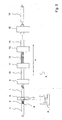
- FIG. 1 1 shows a sketch of a cylindrical dome 1 having at one end a mandrel coupling 2a for coupling to a corresponding mandrel coupling 2b of a preceding dome 1.
- a recess 3 is inserted, in which a radio transponder 4 is inserted and fixed with a plastic compound in the recess 3.
- the top of the plastic mass is rounded so that it fits the cylindrical mandrel surface and connects seamlessly thereto.
- the radio transponder 4 is, for example, a passive RFID (Radio Frequency Identification) transponder, which is supplied with energy of the radio signal during a wireless interrogation by a radio signal and transmits information stored via the assigned mandrel 1 with the aid of this energy in the radio transponder 4. This information is in particular a spike identifier.
- RFID Radio Frequency Identification
- FIG. 2 shows a cutaway view of a cylindrical dome 1 in the region of the depression 3. It becomes clear that the radio transponder 4 is fixed at a distance S 1 to the walls of the metallic dome 1 with the aid of the plastic compound in the recess.
- the plastic mass is much softer than the mandrel surface, but not shielding.
- FIG. 3 lets recognize a manufacturing device 5, in which the in the FIG. 1 sketched dome 1 are coupled together and are transported continuously in a feed direction V through the manufacturing facility.
- a Dornkoppelaggregats not shown
- a Dornkennung from the radio transponder 4 of a moving through the transponder read-out unit Dome 1 is read using a transponder readout unit 6.
- a Auslesignal on a suitable frequency is emitted with a transponder readout antenna 7, which supplies the radio transponder 4 with energy and causes a stored in a memory of the radio transponder 4 Dornkennung read out of the memory for the associated mandrel 1 and with the help of the radio transponder 4 is sent out.
- the emitted Dornkennung is received with the preferably designed as a ring antenna transponder Auslesean- antenna 7 and evaluated by the transponder readout unit 6.
- the transponder read-out unit 6 is connected to a data processing unit 8, in which the read-out mandrel identifier is stored.
- the data processing unit 8 at least one serial number for the hose sections produced on the mandrel 1 below is assigned to this mandrel identification.
- These serial numbers for the tube sections can later be applied to the manufactured tubes, for example, by applying stickers provided on the surface of the tube sections with the serial numbers of the tubes. Also a laser marking or the like is possible.
- the individual dome 1 can be easily tracked in the manufacturing process, without further reading of the radio transponder 4 is required. Furthermore, it is possible by the transponder technology to check whether the right dome 1 (tools) are in use. A process monitoring is even more possible if the dome identifiers are also read out during the return transport. Then, for example, a discharge of domes 1 can take place if, for example, it has been recognized on the basis of the dome identification that a check, revision or replacement is required.
- an extruder 9 is used to apply a first layer 10, for example of rubber (rubber), to the sequence of domes 1 in a continuous process.
- a strength layer 12 is subsequently applied to this layer 10 by means of a spiraling device 11 by spirally winding a tissue onto the layer.
- a further rubber layer 14 is applied to this strength layer 12 with a further extruder 13.
- the steps of spirally stretching strength layers 12 and rubber layers 14 may be repeated several times.
- the scrims forming the strength layer 12 should be spirally wound in opposite directions alternately.
- the continuous tube is divided with a separator 15 into tube sections 16 and these tube sections 16, which correspond approximately to the length of a dome, as well as the corresponding mandrel 1, on which the tube section is located, separated again.
- the hose sections 16 located on a mandrel 1 can be subdivided into smaller sections and be withdrawn from the mandrel 1 with the aid of a removal device (not shown).
- the transponder readout unit 6 with the connected data processing unit 8 ensures that the tube sections 16 can be associated with the domes 1 on which they were manufactured.
- the number of passes per mandrel 1 can be detected by the manufacturing device 5 and used for quality assurance. Thus, after reaching a fixed number of passes, each mandrel 1 can be subjected to a check or a rejection of the dome 1 can be initiated after a maximum number of passes has been reached.
Landscapes
- Engineering & Computer Science (AREA)
- Mechanical Engineering (AREA)
- Extrusion Moulding Of Plastics Or The Like (AREA)
Description
Die Erfindung betrifft eine Fertigungseinrichtung für schlauchförmige Gebilde durch Aufextrudieren von Gummi und/oder Kunststoff auf rohrförmige Dorne. Die Erfindung betrifft weiterhin einen rohrförmigen Dorn als Träger zur Herstellung schlauchartiger Gebilde durch Auftextrudieren von Gummi und/oder Kunststoff auf die Domoberfläche.The invention relates to a manufacturing device for tubular structures by extruding rubber and / or plastic on tubular mandrels. The invention further relates to a tubular mandrel as a carrier for producing hose-like structures by Auftextrudieren of rubber and / or plastic on the dome surface.
Zur Herstellung von Schläuchen ist bekannt, fortlaufend aneinander gekoppelte, zylindrische Dome in einer Förderrichtung vorzutreiben und Kautschuk- und Festigkeitsträgerschichten auf die Dome aufzubringen. Derartige Schläuche werden beispielsweise für Luftfederbälge in Fahrzeugen verwendet.For the production of hoses it is known to advance continuously coupled cylindrical dome in a conveying direction and to apply rubber and reinforcing layers to the dome. Such hoses are used for example for air spring bellows in vehicles.
Aus
Das Problem der Nutzung von Funktranspondern bei Metallrohren ist jedoch, dass diese oftmals nicht einfach, wie in der
Passive Funktransponder haben zudem das Problem, dass eine ausreichende Signalenergie bei der Funktransponderabfrage in den Funktransponder eingekoppelt werden muss, um ein empfangbares Antwortsignal zu erhalten. Die Abschirmungscharakteristik in der Umgebung der Funktransponder ist daher und zur Sicherstellung einer für die raue Umgebung eines Fertigungsprozesses von besonderer Bedeutung.Passive radio transponders also have the problem that sufficient signal energy in the radio transponder interrogation must be coupled into the radio transponder in order to obtain a receivable response signal. The shielding characteristic in the vicinity of the radio transponders is therefore of particular importance for ensuring a harsh environment of a manufacturing process.
Bei der fortlaufenden Schlauchfertigung mit Domen besteht ein Bedarf, die Qualität der Fertigung zu überwachen und den Fertigungsprozess für die einzelnen Schläuche nachzuvollziehen.Continuous dome hose manufacturing has a need to monitor manufacturing quality and understand the manufacturing process for each hose.
Aufgabe der Erfindung ist es daher, eine verbesserte Fertigungseinrichtung für schlauchförmige Gebilde sowie verbesserte rohrförmige Dome hierzu zu schaffen. Die Aufgabe wird mit einer Fertigungseinrichtung gemäß Anspruch 1 gelöst.The object of the invention is therefore to provide an improved manufacturing facility for tubular structures as well as improved tubular domes thereto. The object is achieved with a production device according to
Es wird somit vorgeschlagen, mit Hilfe eines Funktransponders zu ermöglichen, gefertigte Schlauchabschnitte bestimmten Domen zuzuordnen und für jeden Dorn die Anzahl der auf dem Dorn gefertigten Schlauchabschnitte zu bestimmen. Für den Fall, dass nachträglich ein Dorn als fehlerhaft erkannt wird, können die auf dem Dorn gefertigten Schlauchabschnitte und möglicherweise bereits aus den Schläuchen gefertigte Endprodukte, wie zum Beispiel Luftfedern, identifiziert werden, um diese ggf. zurückzurufen. Weiterhin kann die Aussortierung bzw. Überarbeitung von Domen anhand der mit Hilfe der Funktransponder erfassbaren Anzahl von Durchläufen pro Dorn gesteuert werden.It is thus proposed to make it possible, with the aid of a radio transponder, to associate manufactured tube sections with specific domes and to determine the number of tube sections produced on the mandrel for each spike. In the event that subsequently a mandrel is detected as defective, the hose sections made on the mandrel and possibly already made of the hoses end products, such as air springs, can be identified to recall them if necessary. Furthermore, the sorting or reworking of domes can be controlled by means of the number of passes per mandrel which can be detected with the aid of the radio transponders.
Die Nutzung von Funktranspondern in rohrförmigen Domen gelingt durch das Festlegen des Funktransponders mit einer verschleißfesten Kunststoffmasse in der Ein-senkung und die Bildung der Domoberfläche durch die Kunststoffmasse im Bereich der Einsenkung. Es hat sich gezeigt, dass auf diese Weise die Funktransponder im Fertigungsprozess auch bei aufextrudierten Gummi- und Festigkeitslagen auslesbar sind und die geringe Kunststoffmasse den Fertigungsprozess nicht beeinträchtigt, auch wenn Gummi und/oder Kunststoffschichten auf die Domoberfläche aufextrudiert werden.The use of radio transponders in tubular domes succeeds by setting the radio transponder with a wear-resistant plastic mass in the sinking and the formation of the dome surface by the plastic mass in the region of the depression. It has been shown that in this way the radio transponders in the manufacturing process are readable even with extruded rubber and strength layers and the low plastic mass does not affect the manufacturing process, even if rubber and / or plastic layers are extruded onto the dome surface.
Besonders vorteilhaft ist es, wenn der Dorn aus Metall gebildet und in der Einsenkung zwischen dem Metalldom und dem Funktransponder eine Schicht aus der Kunststoffmasse vorgesehen ist. Durch die Zwischenschicht zwischen dem aus Metall gebildeten Boden der Einsenkung des Domes und dem Funktransponder wird erreicht, dass die Abstrahlcharakteristik des Funktransponders nicht durch die angrenzende Metallschicht beeinträchtigt wird.It is particularly advantageous if the mandrel is formed of metal and a layer of the plastic mass is provided in the depression between the metal dome and the radio transponder. By the intermediate layer between the bottom of the dome formed from metal and the radio transponder, it is achieved that the emission characteristic of the radio transponder is not impaired by the adjacent metal layer.
Als Funktransponder können insbesondere passive Transponder eingesetzt werden, die bei einer drahtlosen Abfrage durch ein Funksignal mit Energie des Funksignals versorgt werden und mit Hilfe dieser Energie im Funktransponder gespeicherte Informationen über den zugeordneten Dorn aussenden. Eine derartige Information kann insbesondere eine dem Dorn zugewiesene Dornkennung sein, die im Funktransponder abgespeichert ist.As a radio transponder passive transponder can be used in particular, which are supplied with a wireless query by a radio signal with energy of the radio signal and send out using this energy stored in the radio transponder information about the associated mandrel. Such information may in particular be a mandrel identifier assigned to the mandrel and stored in the radio transponder.
Bei der Fertigung schlauchförmiger Gebilde mit Hilfe der oben beschriebenen rohrförmigen Dome ist es damit möglich, mit Hilfe der Transponder-Ausleseeinheit die in den Funktranspondern der Dome gespeicherten Informationen auszulesen und zu Zwecken der Qualitätssicherung auszuwerten. Der Verschleiß der einzelnen Dome kann durch die Erfassung der Menge der auf einem Dorn herstellten schlauchartigen Gebilde, d.h. der Erfassung der Durchläufe der Dome durch die Fertigungseinrichtung, bestimmt werden. Eine Zuordnung von Schlauchabschnitten bzw. aus den Schlauchabschnitten hergestellter Produkte, wie beispielsweise Luftfedern, zu den einzelnen Domen wird dadurch ermöglicht, dass eine den Schlauchabschnitten zugewiesene Schlauchabschnittsnummer der Dornkennung für den Dorn zugeordnet wird, auf dem der Schlauchabschnitt gefertigt wurde. Diese Zuordnung wird dann abgespeichert und kann ausgewertet werden.In the production of tubular structures with the aid of the above-described tubular dome, it is thus possible with the aid of the transponder read-out unit to read out the information stored in the radio transponders of the dome and to evaluate it for purposes of quality assurance. The wear of each dome can be determined by detecting the amount of tubular structure fabricated on a mandrel, i. the detection of the passage of the dome by the manufacturing facility, be determined. An association of hose sections or products made of the hose sections, such as air springs, to the individual domes is made possible by assigning a hose section number assigned to the hose sections to the mandrel identification for the mandrel on which the hose section has been manufactured. This assignment is then saved and can be evaluated.
Da sich das Transpondersignal nur eine Kunststoffabdeckung nach oben ausbreiten kann, die rotarische Orientierung der Dome aber beliebig ist, ist es vorteilhaft, das Signal mittels eine Ringantenne auszulesen, durch die die Dome während des Fertigungsprozesses hindurchgeführt werden.Since the transponder signal can propagate only a plastic cover upwards, but the rotational orientation of the dome is arbitrary, it is advantageous to read the signal by means of a ring antenna, through which the dome are passed during the manufacturing process.
Die Erfindung wird beispielhaft nachfolgend anhand der beigefügten Zeichnungen näher erläutert. Es zeigen:
Figur 1- Skizze eines zylindrischen Domes mit Einsenkung und Funktransponder in der Einsenkung;
- Figur 2-
- Ausschnittsansicht eines zylindrischen Doms im Bereich der Einsenkung;
- Figur 3 -
- Skizze einer Fertigungseinrichtung mit Transponder-Ausleseeinheit und Datenverarbeitungseinheit.
- FIG. 1
- Sketch of a cylindrical dome with recess and radio transponder in the recess;
- FIG. 2
- Sectional view of a cylindrical dome in the region of the depression;
- FIG. 3 -
- Sketch of a production facility with transponder readout unit and data processing unit.
In die Dornoberfläche des Doms 1 ist eine Einsenkung 3 eingelassen, in die ein Funktransponder 4 eingelassen und mit einer Kunststoffmasse in der Einsenkung 3 festgelegt ist. Die Oberseite der Kunststoffmasse ist so abgerundet, dass sie an die zylinderförmige Dornoberfläche angepasst ist und nahtlos daran anschließt.In the mandrel surface of the
Zwischen dem Boden und den Seitenwänden der Einsenkung 3 und dem Funktransponder 4 ist jeweils eine Kunststoffschicht vorgesehen, so dass der Funktransponder 4 nicht direkt auf dem aus einer Aluminiumlegierung gebildeten Dorn 1 aufliegt. Auf diese Weise wird verhindert, dass das elektromagnetische Feld bei der Funkabfrage zu stark durch den Dorn 1 gedämpft wird.Between the bottom and the side walls of the
Der Funktransponder 4 ist beispielsweise ein passiver RFID (Radio frequency identification)-Transponder, der bei einer drahtlosen Abfrage durch ein Funksignal mit Energie des Funksignals versorgt wird und mit Hilfe dieser Energie im Funktransponder 4 gespeicherte Information über den zugeordneten Dorn 1 aussendet. Diese Information ist insbesondere eine Dornkennung.The
Da die Vorschubgeschwindigkeit der Dome 1 bekannt ist, können die einzelnen Dome 1 im Fertigungsprozess einfach nachverfolgt werden, ohne dass eine weitere Auslesung des Funktransponders 4 erforderlich ist. Weiterhin ist es durch die Transpondertechnik möglich zu überprüfen, ob die richtigen Dome 1 (Werkzeuge) im Einsatz sind. Eine Prozessüberwachung ist noch vollständiger möglich, wenn die Domenkennungen auch beim Rücktransport ausgelesen werden. Dann kann beispielsweise ein Ausschleusen von Domen 1 erfolgen, wenn anhand der Domenkennung beispielsweise erkannt wurde, dass eine Überprüfung, Überarbeitung oder ein Austausch erforderlich ist.Since the feed rate of the
Im weiteren Fertigungsprozess wird mit einem Extruder 9 eine erste Schicht 10, beispielsweise aus Kautschuk (Gummi) auf die Folge von Domen 1 in einem kontinuierlichen Prozess aufgebracht. Auf diese Schicht 10 wird mit einer Spiralisiervorrichtung 11 anschließend eine Festigkeitsschicht 12 aufgebracht, indem ein Gewebe auf die Schicht aufspiralisiert wird. Anschließend wird auf diese Festigkeitsschicht 12 mit einem weiteren Extruder 13 eine weitere Kautschukschicht 14 aufgetragen. Die Schritte des Aufspiralisierens von Festigkeitsschichten 12 und Kautschukschichten 14 kann mehrfach wiederholt werden. Insbesondere sollte das die Festigkeitsschicht 12 bildende Fadengelege abwechselnd gegensinnig aufspiralisiert werden.In the further manufacturing process, an
Am Ende des Fertigungsprozesses wird der kontinuierliche Schlauch mit einer Trennvorrichtung 15 in Schlauchabschnitte 16 aufgeteilt und diese Schlauchabschnitte 16, die etwa der Länge eines Domes entsprechen, sowie der entsprechende Dorn 1, auf dem sich der Schlauchabschnitt befindet, wieder voneinander getrennt. Die auf einem Dorn 1 befindlichen Schlauchabschnitte 16 können in kleinere Abschnitte unterteilt werden und mit Hilfe einer nicht dargestellten Abziehvorrichtung von dem Dorn 1 abgezogen werden.At the end of the manufacturing process, the continuous tube is divided with a
Bei diesem kontinuierlichen Fertigungsprozess stellt die Transponder-Ausleseeinheit 6 mit der angeschlossenen Datenverarbeitungseinheit 8 sicher, dass die Schlauchabschnitte 16 mit den Domen 1 in Verbindung gebracht werden können, auf denen sie gefertigt wurden. Zudem kann die Anzahl der Durchläufe pro Dorn 1 durch die Fertigungseinrichtung 5 erfasst und zur Qualitätssicherung genutzt werden. So kann nach Erreichen einer festgelegten Anzahl von Durchläufen jeder Dorn 1 einer Überprüfung unterzogen oder eine Aussonderung der Dome 1 nach einer erreichten maximalen Durchlaufanzahl veranlasst werden.In this continuous manufacturing process, the
Claims (3)
- Production device (5) for tubular structures produced by extruding rubber or plastic onto tubular mandrels (1) that are continuously coupled to one another and transported through the production device in a direction of advancement, characterized in that the mandrels are provided with a radio transponder (4), which is intended for storing and emitting a mandrel identification assigned to the mandrel (1), characterized by at least one transponder reading unit (6) with a radio antenna (7) for reading information stored in radio transponders (4) of the mandrels (1) and a data processing unit (8), which is connected to the at least one transponder reading unit (6) and is designed for detecting the assignment of individual tubular structures to a mandrel identification of the mandrel (1) on which the tubular structure has been produced and/or for detecting the quantity of tubular structures produced on a mandrel (1), wherein there is a depression (3) in the mandrel surface and a radio transponder (4) is embedded in the depression (3) and is fixed in the depression (3) by a polymer composition such that the polymer composition forms the mandrel surface in the region of the depression (3), wherein the radio transponder (4) is a passive transponder which, during a wireless enquiry by a radio signal, is supplied with energy of the radio signal and with the aid of this energy emits information concerning the assigned mandrel (1) that is stored in the radio transponder (4).
- Production device according to Claim 1, in which the mandrel (1) is formed from metal and a layer of the polymer composition is provided in the depression (3) between the metal mandrel (1) and the radio transponder (4).
- Production device according to Claim 1 or 2, in which the mandrel (1) is formed from an aluminium alloy.
Applications Claiming Priority (1)
| Application Number | Priority Date | Filing Date | Title |
|---|---|---|---|
| DE102007025647A DE102007025647A1 (en) | 2007-06-01 | 2007-06-01 | Manufacturing device for tubular structures and tubular mandrels thereto |
Publications (3)
| Publication Number | Publication Date |
|---|---|
| EP1997609A2 EP1997609A2 (en) | 2008-12-03 |
| EP1997609A3 EP1997609A3 (en) | 2009-12-02 |
| EP1997609B1 true EP1997609B1 (en) | 2013-09-25 |
Family
ID=39500048
Family Applications (1)
| Application Number | Title | Priority Date | Filing Date |
|---|---|---|---|
| EP08154044.5A Not-in-force EP1997609B1 (en) | 2007-06-01 | 2008-04-04 | Assembly device for tubular structures and tubular bolts for this purpose |
Country Status (2)
| Country | Link |
|---|---|
| EP (1) | EP1997609B1 (en) |
| DE (1) | DE102007025647A1 (en) |
Citations (2)
| Publication number | Priority date | Publication date | Assignee | Title |
|---|---|---|---|---|
| DE10229073C1 (en) * | 2002-06-28 | 2003-12-18 | Contitech Luftfedersyst Gmbh | The assembly for the continuous production of reinforced tubular blanks has coupled mandrels to be coated with the rubber/plastics and reinforcement layers, to be separated and stripped for vulcanizing free of the mandrels |
| US20060082010A1 (en) * | 2004-10-19 | 2006-04-20 | Saggese Stefano M | Intelligent molding environment and method of controlling applied clamp tonnage |
Family Cites Families (5)
| Publication number | Priority date | Publication date | Assignee | Title |
|---|---|---|---|---|
| AU5672400A (en) | 1999-06-11 | 2001-01-02 | Phoenix Ag | Device for controlling and monitoring a conveyor belt, notably a tubular conveyor belt |
| DE10229081B4 (en) | 2002-06-28 | 2007-07-19 | Contitech Luftfedersysteme Gmbh | Method for separating hoses and apparatus for carrying out the method |
| AT7303U1 (en) * | 2003-09-10 | 2005-01-25 | Engel Austria Gmbh | INJECTION MOLDING |
| DE202005007844U1 (en) * | 2005-05-13 | 2006-09-21 | Wetzel Gmbh | Embossing calender, for embossing flat sheet material, has processing roller holding parts joined to allow relative displacement and tilting for rapid interchange of embossing sleeves |
| AR050177A1 (en) | 2005-07-21 | 2006-10-04 | Siderca Sa Ind & Com | "A SET OF METAL TUBE AND RADIO FREQUENCY IDENTIFICATION LABELS (RFID)" |
-
2007
- 2007-06-01 DE DE102007025647A patent/DE102007025647A1/en not_active Withdrawn
-
2008
- 2008-04-04 EP EP08154044.5A patent/EP1997609B1/en not_active Not-in-force
Patent Citations (2)
| Publication number | Priority date | Publication date | Assignee | Title |
|---|---|---|---|---|
| DE10229073C1 (en) * | 2002-06-28 | 2003-12-18 | Contitech Luftfedersyst Gmbh | The assembly for the continuous production of reinforced tubular blanks has coupled mandrels to be coated with the rubber/plastics and reinforcement layers, to be separated and stripped for vulcanizing free of the mandrels |
| US20060082010A1 (en) * | 2004-10-19 | 2006-04-20 | Saggese Stefano M | Intelligent molding environment and method of controlling applied clamp tonnage |
Also Published As
| Publication number | Publication date |
|---|---|
| EP1997609A2 (en) | 2008-12-03 |
| EP1997609A3 (en) | 2009-12-02 |
| DE102007025647A1 (en) | 2008-12-04 |
Similar Documents
| Publication | Publication Date | Title |
|---|---|---|
| EP0753472B1 (en) | Method and arrangement for monitoring a conveyor belt | |
| EP3634783B1 (en) | Vehicle tyre | |
| DE102016102040A1 (en) | Printing machine for printing on containers | |
| WO2003030093A2 (en) | Transponder label and method for the production thereof | |
| WO2018224194A1 (en) | Vehicle tire | |
| DE202020005420U1 (en) | Processing unit for inserting electronic devices, which are suitable for high-frequency communication, into corresponding rubber sleeves | |
| EP1517770A1 (en) | Method and device for the separation of tubes | |
| EP0996087B1 (en) | Device and method for manufacturing a track, namely a transponder strip | |
| EP3397870B1 (en) | Sliding bearing with wear monitoring and associated method | |
| EP1997609B1 (en) | Assembly device for tubular structures and tubular bolts for this purpose | |
| EP3568730B1 (en) | Monitoring and control of a milling operation | |
| WO1999050788A1 (en) | Device for marking objects | |
| DE102014104416B4 (en) | Fiber laying head | |
| EP3910219B1 (en) | Method for manufacturing tubings and pipelines with rfid chips | |
| EP3760439A2 (en) | Method and device for manufacturing a strip of material with an integrated electronic component | |
| DE10229082B3 (en) | Method and device for producing strength-reinforced, tubular structures | |
| DE102016208981B4 (en) | Process for the production of gas bags | |
| EP4031307A1 (en) | Transport system for a tube, a wire or a metal sheet, and method for delivering a tube, a wire or a metal sheet | |
| DE102017218763A1 (en) | A method of forming a non-contact readable identification unit in a tire | |
| DE102021206882A1 (en) | Process for manufacturing hoses and pipelines with RFID chips | |
| EP4113359A1 (en) | Method for manufacturing tubing and pipelines with rfid chips | |
| DE102021209184A1 (en) | Process for manufacturing hoses and pipelines with RFID chips | |
| DE102022210359A1 (en) | Radio transponder | |
| EP3972798B1 (en) | Method and device for producing a rubber component | |
| DE102017123273A1 (en) | UHF data carrier and method for its production |
Legal Events
| Date | Code | Title | Description |
|---|---|---|---|
| PUAI | Public reference made under article 153(3) epc to a published international application that has entered the european phase |
Free format text: ORIGINAL CODE: 0009012 |
|
| AK | Designated contracting states |
Kind code of ref document: A2 Designated state(s): AT BE BG CH CY CZ DE DK EE ES FI FR GB GR HR HU IE IS IT LI LT LU LV MC MT NL NO PL PT RO SE SI SK TR |
|
| AX | Request for extension of the european patent |
Extension state: AL BA MK RS |
|
| PUAL | Search report despatched |
Free format text: ORIGINAL CODE: 0009013 |
|
| AK | Designated contracting states |
Kind code of ref document: A3 Designated state(s): AT BE BG CH CY CZ DE DK EE ES FI FR GB GR HR HU IE IS IT LI LT LU LV MC MT NL NO PL PT RO SE SI SK TR |
|
| AX | Request for extension of the european patent |
Extension state: AL BA MK RS |
|
| RIC1 | Information provided on ipc code assigned before grant |
Ipc: B29C 47/92 20060101ALI20091028BHEP Ipc: B29C 33/76 20060101AFI20091028BHEP |
|
| 17P | Request for examination filed |
Effective date: 20100602 |
|
| 17Q | First examination report despatched |
Effective date: 20100708 |
|
| AKX | Designation fees paid |
Designated state(s): AT BE BG CH CY CZ DE DK EE ES FI FR GB GR HR HU IE IS IT LI LT LU LV MC MT NL NO PL PT RO SE SI SK TR |
|
| GRAP | Despatch of communication of intention to grant a patent |
Free format text: ORIGINAL CODE: EPIDOSNIGR1 |
|
| INTG | Intention to grant announced |
Effective date: 20130614 |
|
| GRAS | Grant fee paid |
Free format text: ORIGINAL CODE: EPIDOSNIGR3 |
|
| GRAA | (expected) grant |
Free format text: ORIGINAL CODE: 0009210 |
|
| AK | Designated contracting states |
Kind code of ref document: B1 Designated state(s): AT BE BG CH CY CZ DE DK EE ES FI FR GB GR HR HU IE IS IT LI LT LU LV MC MT NL NO PL PT RO SE SI SK TR |
|
| REG | Reference to a national code |
Ref country code: GB Ref legal event code: FG4D Free format text: NOT ENGLISH |
|
| REG | Reference to a national code |
Ref country code: CH Ref legal event code: EP |
|
| REG | Reference to a national code |
Ref country code: AT Ref legal event code: REF Ref document number: 633524 Country of ref document: AT Kind code of ref document: T Effective date: 20131015 |
|
| REG | Reference to a national code |
Ref country code: IE Ref legal event code: FG4D Free format text: LANGUAGE OF EP DOCUMENT: GERMAN |
|
| REG | Reference to a national code |
Ref country code: DE Ref legal event code: R096 Ref document number: 502008010717 Country of ref document: DE Effective date: 20131121 |
|
| PG25 | Lapsed in a contracting state [announced via postgrant information from national office to epo] |
Ref country code: HR Free format text: LAPSE BECAUSE OF FAILURE TO SUBMIT A TRANSLATION OF THE DESCRIPTION OR TO PAY THE FEE WITHIN THE PRESCRIBED TIME-LIMIT Effective date: 20130925 Ref country code: SE Free format text: LAPSE BECAUSE OF FAILURE TO SUBMIT A TRANSLATION OF THE DESCRIPTION OR TO PAY THE FEE WITHIN THE PRESCRIBED TIME-LIMIT Effective date: 20130925 Ref country code: NO Free format text: LAPSE BECAUSE OF FAILURE TO SUBMIT A TRANSLATION OF THE DESCRIPTION OR TO PAY THE FEE WITHIN THE PRESCRIBED TIME-LIMIT Effective date: 20131225 Ref country code: LT Free format text: LAPSE BECAUSE OF FAILURE TO SUBMIT A TRANSLATION OF THE DESCRIPTION OR TO PAY THE FEE WITHIN THE PRESCRIBED TIME-LIMIT Effective date: 20130925 |
|
| REG | Reference to a national code |
Ref country code: NL Ref legal event code: VDEP Effective date: 20130925 |
|
| REG | Reference to a national code |
Ref country code: LT Ref legal event code: MG4D |
|
| PG25 | Lapsed in a contracting state [announced via postgrant information from national office to epo] |
Ref country code: FI Free format text: LAPSE BECAUSE OF FAILURE TO SUBMIT A TRANSLATION OF THE DESCRIPTION OR TO PAY THE FEE WITHIN THE PRESCRIBED TIME-LIMIT Effective date: 20130925 Ref country code: SI Free format text: LAPSE BECAUSE OF FAILURE TO SUBMIT A TRANSLATION OF THE DESCRIPTION OR TO PAY THE FEE WITHIN THE PRESCRIBED TIME-LIMIT Effective date: 20130925 Ref country code: LV Free format text: LAPSE BECAUSE OF FAILURE TO SUBMIT A TRANSLATION OF THE DESCRIPTION OR TO PAY THE FEE WITHIN THE PRESCRIBED TIME-LIMIT Effective date: 20130925 Ref country code: GR Free format text: LAPSE BECAUSE OF FAILURE TO SUBMIT A TRANSLATION OF THE DESCRIPTION OR TO PAY THE FEE WITHIN THE PRESCRIBED TIME-LIMIT Effective date: 20131226 |
|
| PG25 | Lapsed in a contracting state [announced via postgrant information from national office to epo] |
Ref country code: IS Free format text: LAPSE BECAUSE OF FAILURE TO SUBMIT A TRANSLATION OF THE DESCRIPTION OR TO PAY THE FEE WITHIN THE PRESCRIBED TIME-LIMIT Effective date: 20140125 Ref country code: RO Free format text: LAPSE BECAUSE OF FAILURE TO SUBMIT A TRANSLATION OF THE DESCRIPTION OR TO PAY THE FEE WITHIN THE PRESCRIBED TIME-LIMIT Effective date: 20130925 Ref country code: NL Free format text: LAPSE BECAUSE OF FAILURE TO SUBMIT A TRANSLATION OF THE DESCRIPTION OR TO PAY THE FEE WITHIN THE PRESCRIBED TIME-LIMIT Effective date: 20130925 Ref country code: SK Free format text: LAPSE BECAUSE OF FAILURE TO SUBMIT A TRANSLATION OF THE DESCRIPTION OR TO PAY THE FEE WITHIN THE PRESCRIBED TIME-LIMIT Effective date: 20130925 Ref country code: CZ Free format text: LAPSE BECAUSE OF FAILURE TO SUBMIT A TRANSLATION OF THE DESCRIPTION OR TO PAY THE FEE WITHIN THE PRESCRIBED TIME-LIMIT Effective date: 20130925 Ref country code: EE Free format text: LAPSE BECAUSE OF FAILURE TO SUBMIT A TRANSLATION OF THE DESCRIPTION OR TO PAY THE FEE WITHIN THE PRESCRIBED TIME-LIMIT Effective date: 20130925 |
|
| PG25 | Lapsed in a contracting state [announced via postgrant information from national office to epo] |
Ref country code: PL Free format text: LAPSE BECAUSE OF FAILURE TO SUBMIT A TRANSLATION OF THE DESCRIPTION OR TO PAY THE FEE WITHIN THE PRESCRIBED TIME-LIMIT Effective date: 20130925 Ref country code: CY Free format text: LAPSE BECAUSE OF FAILURE TO SUBMIT A TRANSLATION OF THE DESCRIPTION OR TO PAY THE FEE WITHIN THE PRESCRIBED TIME-LIMIT Effective date: 20130925 Ref country code: ES Free format text: LAPSE BECAUSE OF FAILURE TO SUBMIT A TRANSLATION OF THE DESCRIPTION OR TO PAY THE FEE WITHIN THE PRESCRIBED TIME-LIMIT Effective date: 20130925 |
|
| REG | Reference to a national code |
Ref country code: DE Ref legal event code: R097 Ref document number: 502008010717 Country of ref document: DE |
|
| PG25 | Lapsed in a contracting state [announced via postgrant information from national office to epo] |
Ref country code: PT Free format text: LAPSE BECAUSE OF FAILURE TO SUBMIT A TRANSLATION OF THE DESCRIPTION OR TO PAY THE FEE WITHIN THE PRESCRIBED TIME-LIMIT Effective date: 20140127 |
|
| PLBE | No opposition filed within time limit |
Free format text: ORIGINAL CODE: 0009261 |
|
| STAA | Information on the status of an ep patent application or granted ep patent |
Free format text: STATUS: NO OPPOSITION FILED WITHIN TIME LIMIT |
|
| PG25 | Lapsed in a contracting state [announced via postgrant information from national office to epo] |
Ref country code: IT Free format text: LAPSE BECAUSE OF FAILURE TO SUBMIT A TRANSLATION OF THE DESCRIPTION OR TO PAY THE FEE WITHIN THE PRESCRIBED TIME-LIMIT Effective date: 20130925 |
|
| 26N | No opposition filed |
Effective date: 20140626 |
|
| PG25 | Lapsed in a contracting state [announced via postgrant information from national office to epo] |
Ref country code: DK Free format text: LAPSE BECAUSE OF FAILURE TO SUBMIT A TRANSLATION OF THE DESCRIPTION OR TO PAY THE FEE WITHIN THE PRESCRIBED TIME-LIMIT Effective date: 20130925 |
|
| REG | Reference to a national code |
Ref country code: DE Ref legal event code: R097 Ref document number: 502008010717 Country of ref document: DE Effective date: 20140626 |
|
| PG25 | Lapsed in a contracting state [announced via postgrant information from national office to epo] |
Ref country code: MC Free format text: LAPSE BECAUSE OF FAILURE TO SUBMIT A TRANSLATION OF THE DESCRIPTION OR TO PAY THE FEE WITHIN THE PRESCRIBED TIME-LIMIT Effective date: 20130925 Ref country code: LU Free format text: LAPSE BECAUSE OF FAILURE TO SUBMIT A TRANSLATION OF THE DESCRIPTION OR TO PAY THE FEE WITHIN THE PRESCRIBED TIME-LIMIT Effective date: 20140404 |
|
| REG | Reference to a national code |
Ref country code: CH Ref legal event code: PL |
|
| GBPC | Gb: european patent ceased through non-payment of renewal fee |
Effective date: 20140404 |
|
| REG | Reference to a national code |
Ref country code: FR Ref legal event code: ST Effective date: 20141231 |
|
| REG | Reference to a national code |
Ref country code: IE Ref legal event code: MM4A |
|
| PG25 | Lapsed in a contracting state [announced via postgrant information from national office to epo] |
Ref country code: GB Free format text: LAPSE BECAUSE OF NON-PAYMENT OF DUE FEES Effective date: 20140404 Ref country code: CH Free format text: LAPSE BECAUSE OF NON-PAYMENT OF DUE FEES Effective date: 20140430 Ref country code: LI Free format text: LAPSE BECAUSE OF NON-PAYMENT OF DUE FEES Effective date: 20140430 |
|
| PG25 | Lapsed in a contracting state [announced via postgrant information from national office to epo] |
Ref country code: FR Free format text: LAPSE BECAUSE OF NON-PAYMENT OF DUE FEES Effective date: 20140430 |
|
| PG25 | Lapsed in a contracting state [announced via postgrant information from national office to epo] |
Ref country code: IE Free format text: LAPSE BECAUSE OF NON-PAYMENT OF DUE FEES Effective date: 20140404 |
|
| REG | Reference to a national code |
Ref country code: AT Ref legal event code: MM01 Ref document number: 633524 Country of ref document: AT Kind code of ref document: T Effective date: 20140404 |
|
| PG25 | Lapsed in a contracting state [announced via postgrant information from national office to epo] |
Ref country code: AT Free format text: LAPSE BECAUSE OF NON-PAYMENT OF DUE FEES Effective date: 20140404 |
|
| PG25 | Lapsed in a contracting state [announced via postgrant information from national office to epo] |
Ref country code: MT Free format text: LAPSE BECAUSE OF FAILURE TO SUBMIT A TRANSLATION OF THE DESCRIPTION OR TO PAY THE FEE WITHIN THE PRESCRIBED TIME-LIMIT Effective date: 20130925 |
|
| PG25 | Lapsed in a contracting state [announced via postgrant information from national office to epo] |
Ref country code: BG Free format text: LAPSE BECAUSE OF FAILURE TO SUBMIT A TRANSLATION OF THE DESCRIPTION OR TO PAY THE FEE WITHIN THE PRESCRIBED TIME-LIMIT Effective date: 20130925 |
|
| PG25 | Lapsed in a contracting state [announced via postgrant information from national office to epo] |
Ref country code: TR Free format text: LAPSE BECAUSE OF FAILURE TO SUBMIT A TRANSLATION OF THE DESCRIPTION OR TO PAY THE FEE WITHIN THE PRESCRIBED TIME-LIMIT Effective date: 20130925 Ref country code: BE Free format text: LAPSE BECAUSE OF FAILURE TO SUBMIT A TRANSLATION OF THE DESCRIPTION OR TO PAY THE FEE WITHIN THE PRESCRIBED TIME-LIMIT Effective date: 20140430 Ref country code: HU Free format text: LAPSE BECAUSE OF FAILURE TO SUBMIT A TRANSLATION OF THE DESCRIPTION OR TO PAY THE FEE WITHIN THE PRESCRIBED TIME-LIMIT; INVALID AB INITIO Effective date: 20080404 |
|
| PGFP | Annual fee paid to national office [announced via postgrant information from national office to epo] |
Ref country code: DE Payment date: 20200430 Year of fee payment: 13 |
|
| REG | Reference to a national code |
Ref country code: DE Ref legal event code: R119 Ref document number: 502008010717 Country of ref document: DE |
|
| PG25 | Lapsed in a contracting state [announced via postgrant information from national office to epo] |
Ref country code: DE Free format text: LAPSE BECAUSE OF NON-PAYMENT OF DUE FEES Effective date: 20211103 |