EP1997437A2 - Wundnahtwickelvorrichtung und Verfahren zu ihrer Anwendung - Google Patents
Wundnahtwickelvorrichtung und Verfahren zu ihrer Anwendung Download PDFInfo
- Publication number
- EP1997437A2 EP1997437A2 EP08251863A EP08251863A EP1997437A2 EP 1997437 A2 EP1997437 A2 EP 1997437A2 EP 08251863 A EP08251863 A EP 08251863A EP 08251863 A EP08251863 A EP 08251863A EP 1997437 A2 EP1997437 A2 EP 1997437A2
- Authority
- EP
- European Patent Office
- Prior art keywords
- suture
- holder
- array
- arm
- rods
- Prior art date
- Legal status (The legal status is an assumption and is not a legal conclusion. Google has not performed a legal analysis and makes no representation as to the accuracy of the status listed.)
- Granted
Links
Images







Classifications
-
- A—HUMAN NECESSITIES
- A61—MEDICAL OR VETERINARY SCIENCE; HYGIENE
- A61B—DIAGNOSIS; SURGERY; IDENTIFICATION
- A61B17/00—Surgical instruments, devices or methods
- A61B17/04—Surgical instruments, devices or methods for suturing wounds; Holders or packages for needles or suture materials
- A61B17/06—Needles ; Sutures; Needle-suture combinations; Holders or packages for needles or suture materials
- A61B17/06114—Packages or dispensers for needles or sutures
- A61B17/06133—Packages or dispensers for needles or sutures of parallelepipedal shape, e.g. made of rectangular or slightly oval panels
-
- A—HUMAN NECESSITIES
- A61—MEDICAL OR VETERINARY SCIENCE; HYGIENE
- A61B—DIAGNOSIS; SURGERY; IDENTIFICATION
- A61B17/00—Surgical instruments, devices or methods
- A61B17/04—Surgical instruments, devices or methods for suturing wounds; Holders or packages for needles or suture materials
- A61B17/06—Needles ; Sutures; Needle-suture combinations; Holders or packages for needles or suture materials
- A61B17/06166—Sutures
-
- A—HUMAN NECESSITIES
- A61—MEDICAL OR VETERINARY SCIENCE; HYGIENE
- A61B—DIAGNOSIS; SURGERY; IDENTIFICATION
- A61B17/00—Surgical instruments, devices or methods
- A61B17/04—Surgical instruments, devices or methods for suturing wounds; Holders or packages for needles or suture materials
- A61B17/06—Needles ; Sutures; Needle-suture combinations; Holders or packages for needles or suture materials
- A61B17/06195—Apparatus or means for preparing the cut end of the suture thread to be attached to the needle, e.g. tipping to prevent brooming
-
- A—HUMAN NECESSITIES
- A61—MEDICAL OR VETERINARY SCIENCE; HYGIENE
- A61B—DIAGNOSIS; SURGERY; IDENTIFICATION
- A61B17/00—Surgical instruments, devices or methods
- A61B2017/00526—Methods of manufacturing
-
- A—HUMAN NECESSITIES
- A61—MEDICAL OR VETERINARY SCIENCE; HYGIENE
- A61B—DIAGNOSIS; SURGERY; IDENTIFICATION
- A61B17/00—Surgical instruments, devices or methods
- A61B17/04—Surgical instruments, devices or methods for suturing wounds; Holders or packages for needles or suture materials
- A61B17/06—Needles ; Sutures; Needle-suture combinations; Holders or packages for needles or suture materials
- A61B17/06114—Packages or dispensers for needles or sutures
- A61B2017/06142—Packages or dispensers for needles or sutures having needle- or suture- retaining members, e.g. holding tabs or needle parks
Definitions
- the present disclosure relates to devices and methods for packaging sutures and, more particularly, to a suture winding device and methods for use thereof.
- Packages for surgical sutures having needles attached at one or both ends are typically constructed according to the nature of the suture material and to how the sutures will be used. Generally, the package holds the suture and attached needles in place, protects them during handling and storage, and allows ready access to the suture for removal with minimum handling at the time the suture is to be used.
- the packages are loaded with one or more needles that have a desired quantity of suture attached.
- the attached suture is generally looped within the package using tracks, rods, posts, or other suitable positioning structures located within the package.
- U.S. Patent No. 5,123,528 to Brown et al. currently owned and assigned to United States Surgical, that discloses a package having a number of tracks and a needle receiving park.
- Each track has a suture receiving port and an opposed vacuum port.
- a quantity of suture is drawn through the suture receiving port and received in the track.
- a needle attached to the suture is positioned in the needle receiving park.
- a device for winding a quantity of suture attached to a needle is disclosed in U.S. Patent No. 5,473,854 to Demarest et al . that discloses an apparatus having a number of workstations for packaging needles with an attached suture. As a turntable of the apparatus rotates, a tool nest attached to the turntable is rotated from one workstation to the next workstation. Each workstation performs a specific task with respect to packaging the needle with attached suture.
- the apparatus includes a base member, which may be rotatably mounted to a plate, a needle holder disposed within the base member, at least one needle that is adapted for releasable engagement with the needle holder and attached to a quantity of suture, a retainer package disposed atop the base member and including a first member having a plurality of throughholes, a plurality of rods configured in at least one array that are engagable with, and correspond to, the throughholdes, and a holder having open and closed states.
- the holder is movable relative to the base member between a first position and at least one subsequent position, either manually or automatically, and includes a first arm and a second arm.
- first and second arms are in spaced apart relation and in the closed state, at least a portion of the first arm is in substantial contact with at least a portion of the second arm.
- the holder may slidably engage at least a portion of the suture in the closed state such that a predetermined amount of tension may be applied thereto.
- the first member of the retainer may be adapted to receive the needle in the needle holder and may additionally include a slot for receiving a portion of the suture.
- the rods of the at least one array are movable from a retracted position to an extended position in which the rods are releasably engagable with the suture.
- rotation of the base member corresponds to movement of the rods into the extended position such that at least a portion of the suture is wound about the rods thereby forming a plurality of loops.
- the at least one array includes a first array and at least one additional array.
- the rods of the first array and the at least one additional array are independently and sequentially movable from the retracted position to the extended position and are arranged in a first arc and at least one additional arc.
- the first arc may define a smaller radius than the at least one additional arc such that each of the plurality of loops are in space apart relation and each define a diameter that is larger than that of the previous loop.
- an apparatus for packaging a suture in another embodiment, includes a base member having a first holder disposed therein, at least one array disposed substantially along a longitudinal axis of the base member and including at least one rod, a retainer package that has at least a first member with at least one throughhole configured to releasably receive the at least one rod of the at least one array, a second holder that includes first and second arms, and a parking mechanism having open and closed conditions.
- the second holder is movably connected to the base member and is movable between a first position and at least one subsequent position.
- the first and second arms of the parking mechanism are in spaced apart relation, and in the closed condition, at least a portion of the first arm is in substantial contact with at least a portion of the second arm.
- the parking mechanism may be movable relative to the base member between a first position and at least one subsequent position.
- the present disclosure contemplates that the parking mechanism may be in the closed condition when the parking mechanism is in the at least one subsequent position, and that in the closed condition, the parking mechanism releasably retains at least a portion of the suture.
- the apparatus may also include at least one positioning rod that is movable from a retracted position to an extended position in which the at least one positioning rod is engagable with at least a portion of the suture.
- the at least one positioning rod is in the extended position when the parking mechanism is in the at least one subsequent position such that at least a portion of the suture is disposed within the parking device and about the positioning rod.
- At least a portion of the suture may form an angle with respect to an axis of the base member that is in the range of approximately 0° to approximately 180°.
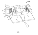
- the suture winding device shown generally as 100, includes a base 10 that is rotatably attached to a support plate 1 and is rotatable about a central point A.
- base 10 includes a frame 18 and a plate 19 that is attached to a mounting surface 26 of frame 18.
- frame 18, and plate 19 have a generally oval or elongate elliptical configuration. Other shapes may also be used and are contemplated herein.
- Base 10 further includes a plurality of vacuum connections 12 where each vacuum connection includes a vacuum port 12a.
- Each vacuum connection 12 is fluidly coupled to a vacuum source (not shown) such as would be known by a person of ordinary skill in the art.
- the actuation of vacuum connections 12 i.e. applying negative pressure or suction to vacuum ports 12a may be controlled manually or automatically.
- a plurality of rods 22 is arranged on plate 19 and at least a portion of each rod 22 extends through top surface 24.
- Each rod 22 includes a tip 23 that is configured and dimensioned to extend beyond a top surface of a mounting member 7 ( FIG. 2 ).
- rods 22 include interior rods 22a and exterior rods 22b.
- the plurality of rods 22 may be arranged to form a first array 20a and a second array 20b.
- first array 20a and second array 20b are generally arcuate arrangements of exterior rods 22b that are spaced apart along a longitudinal axis of base 10.
- a needle holder 50 is disposed in a central region of mounting member 7 ( FIG. 2 ) and separates first array 20a from second array 20b.
- Mounting member 7 is disposed on base 10 such that it abuts top surface 24.
- Needle holder 50 is releasably disposed in mounting member 7 and includes a plate 52 having a plurality of buttons 54 disposed thereon.
- buttons 54 are arranged in pairs to form one or more needle channels 64.
- Each needle channel 64 is configured and adapted for releasably engaging a needle 14 ( FIG. 5 ).
- Needle 14, as is known in the art, has a sharpened tip at one end and a length of suture 16 extending from an opposing end.
- a post 56 Disposed on one end of plate 52 are a post 56, a needle guide 58, and an end member 60.
- Post 56 and end member 60 are spaced apart to form a suture channel 62 therebetween.
- Needle guide 58 in cooperation with buttons 54 position needle 14 in needle holder 50 such that suture 16 is releasably received in suture channel 62 ( FIG. 5 ).
- suture 16 is positioned on mounting member 7 such that it contacts at least one interior rod 22a ( FIG. 5 ).
- Needle holder 50 may be replaced by alternate embodiments of the needle holder that are configured to receive single needles, double needles, or needles of varying diameters and dimensions regardless of whether the needles are in a single or double configuration.
- a suture package or retainer 70 ( FIG. 17 ) is positionable on base 10 as illustrated in FIGS. 6-8 and 15 .
- a suitable retainer 70 is the subject matter of U.S. Patent Application Serial Number 10/891,604 filed on July 15, 2004 , currently owned and assigned to Tyco Healthcare Group, the contents of which are hereby incorporated by reference in their entirety.
- retainer 70 includes a first member 72 and a second member 74. Second member 74 is adapted to attach to first member 72 as will be discussed in further detail below.
- first member 72 is shown disposed on mounting member 7 of base 10.
- the position of first member 72 with respect to mounting member 7 is maintained by vacuum connections 12 ( FIG. 1 ) that are disposed in base 10. More specifically, vacuum applied through vacuum connections 12 holds first member 72 to vacuum ports 12a.
- First member 72 is disposed on top of mounting member 7.
- needle 14 Positioned between first member 72 and mounting member 7 is needle 14 with a length of suture 16 attached thereto.
- First member 72 includes a plurality of throughholes 76 arranged to correspond with rods 22 ( FIG. 1 ) of base 10 thereby aligning needle holder 50 with a needle park or needle grip 80 of first member 72. As shown in FIG.
- first member 72 includes needle park 80 for releasably attaching needle 14 to first member 72.
- Needle park 80 is positioned on first member 72 such that is aligned with needle holder 50 when first member 72 is positioned on plate 19 by the cooperative arrangement of rods 22 and throughholes 76.
- needle park 80 may be replaced by alternate embodiments that are configured to receive single needles, double needles, or needles of varying diameters and dimensions regardless of whether the needles are in a single or double configuration.
- Needle park 80 includes a number of tabs 82 and notches 84 that extend from a surface of first member 72 towards plate 19.
- needle holder 80 is disposed in a recess 86 on an underside of first member 72.
- Each tab 82 and its corresponding notch 84 are configured and adapted for releasably gripping needle 14 such that when retainer 70 is removed from base 10, needle 14 separates from needle holder 50 and is releasably attached to retainer 70 by needle park 80.
- Tabs 82 and notches 84 are biased towards each other for releasably receiving needle 14.
- a slot 78 is disposed along an edge of first member 72 where slot 78 communicates with recess 86 such that a portion of suture 16 may extend through recess 86 and be accessed from outside retainer 70.
- Transfer of needle 14 from needle holder 50 to needle park 80 is affected by forces applied by an operator in a generally downward direction (i.e. towards plate 19) on first member 72.
- first member 72 As first member 72 is urged towards plate 19 and needle holder 50, needle 14 contacts needle park 80 with sufficient force to overcome the bias of tab 82 and notches 84.
- the space between tab 82 and notches 84 is sufficient to receive needle 14.
- needle 14 no longer urges tab 82 and notches 84 away from each other whereupon the bias of tab 82 and notches 84 act to urge them towards each other for releasably retaining needle 14.
- each set of tab 82 and notches 84 is configured as previously described.
- vacuum applied to first member 72 through vacuum ports 12a may supply the forces that urge needle 14 into releasable engagement with needle park 80 as previously discussed.
- a combination of applied vacuum and operator action supply the forces for urging needle 14 into releasable engagement with needle park 80.
- Base 10 is rotatable such that suture 16 contacts each exterior rod 22b sequentially. As base 10 completes each rotation, a loop of suture 16 is formed about exterior rods 22b. A predetermined amount of tension is maintained on suture 16 by a holder 30.
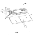
- Holder 30 is mounted to support plate 1 and is rotatable with respect to base 10. In one embodiment, holder 30 is rotatable amongst a plurality of positions including a loading position ( FIG. 1 ) and an unloading position ( FIG. 7 ). In addition, holder 30 is rotatable amongst the plurality of positions while base 10 is rotating about the central point (i.e. base 10 and holder 30 are independently positionable).
- holder 30 is attached to a mounting arm 42 ( FIG. 1 ) that is rotatably attached to plate 1 and is capable of being positioned in at least the loading position and the unloading position of holder 30 and, preferably may be positioned in any position therebetween. Further still, mounting arm 42 is capable of being positioned independently of base 10.
- a suture winding device 90 includes a holder 92 that is rotatably attached to a plate 94 and movable through a plurality of positions, e.g. loading and unloading positions, as discussed above with respect to the embodiment depicted in FIGS. 1-7 .
- suture winding device 90 includes a programmable control module, actuator, or the like, generally designated by reference numeral 96, that is operatively connected to holder 92 such that movement through the plurality of positions may be either manually or automatically regulated.
- holder 30 in the loading position, holder 30 orients suture 16 such that a desired angle between suture 16 and base 10 is achieved. In the unloading position, holder 30 orients suture 16 such that it is substantially parallel to the longitudinal axis of base 10. The predetermined amount of tension applied to suture 16 is maintained by holder 30 regardless of its position relative to base 10 or whether or not base 10 is being rotated.
- holder 30 includes a first arm 32 and a second arm 34.
- First arm 32 is movable such that holder 30 may transition between an open state and a closed state while second arm 34 is stationary.
- second arm 34 is fixedly attached to a block 48 that is, in turn, fixedly attached to a mounting block 47 that is attached to a wall 40.
- Mounting block 47 includes an actuator and a slot 38 therein. Slot 38 is configured and dimensioned for slidably receiving a driver arm 36.
- First arm 32 is attached to driver arm 36 such that movement of driver arm 36 results in corresponding movement of first arm 32.
- driver arm 36 is movable in slot 38 in a substantially vertical direction. In the open state, first arm 32 is spaced apart from second arm 34 defining a gap 45 therebetween ( FIG. 3 ). Gap 45 has sufficient dimensions such that suture 16 may be fed through gap 45 without contacting either first or second arms 32, 34.
- First arm 32 is moved towards second arm 34 during an actuation sequence such that first arm 32 substantially abuts second arm 34.
- first and second arms 32, 34 may include respective first and second cushioning members 32a, 34a.
- a pressure source is fluidly coupled to actuation ports 46 to provide the motive force to operate the actuator.
- Known pressure sources such as pneumatics (e.g. air, compressed gases, vacuum) or hydraulics (e.g. water, saline, oil) may be used with the actuator.
- the actuator may be electrically powered by either AC or DC sources. Pneumatic, hydraulic, or electric actuators are well known to one skilled in this art and will not be discussed in detail herein.
- first arm 32 Upon actuation, the actuator imparts motion to driver arm 36 to move driver arm 36 generally downward thereby transitioning it from its open state to its closed state.
- first arm 32 abuts second arm 34 and for slidably capturing a section of suture 16 therebetween.
- the amount of force exerted on suture 16 by first and second arms 32, 34 in the closed state is adjustable such that the amount of pressure applied is sufficient to allow suture 16 to be fed from a source to form the loops as base 10 rotates while maintaining the desired amount of tension on suture 16. Additionally, the amount of pressure applied by first and second arms 32, 34 minimizes drooping of a length of suture 16 extending between holder 30 and first member 72 when base 10 is stationary.
- suture 16 is disposed within retainer 70 with a substantially uniform amount of applied tension. Additionally, holder 30, in cooperation with a uniform arrangement of rods 22, supplies the desired amount of tension to suture 16 during the winding process thereby distributing suture 16 in retainer 70 in a substantially uniform arrangement.
- one or both of the first and second arms of the holder are movable relative to each other.
- the first arm may move toward the second arm, the second arm may move toward the first arm, or both arms may move towards each other.
- a programmable control module, actuator, or the like may be operatively connected to one or both of the first and second arms of the holder such that the approximation thereof may be manually or automatically regulated.
- first and second members 72, 74 are press fit together using applied pressure to engage corresponding edge portions of respective first and second members 72, 74 as is known in the art.
- first and second members 72, 74 are joined together using a heat stake 110, such as those known in the art and illustrated in FIG. 9 .
- Heat stake 110 includes a die plate 112 that is positionable along a vertical axis of heat stake 110. After retainer 70 is assembled (i.e. second member 74 is placed on top of first member 72), base 10 and retainer 70 are positioned such that die plate 112 is in substantial vertical alignment with retainer 70 by moving plate 1 along a horizontal set of rails or guides 122 that are mounted on plate 120. Plate 1, including base 10, is slidably attached to rails 122 using structures that are known in the art. In the alternative, base 10 may be stationary and heat stake 110 may be positionable along a horizontal set of rails or guides towards or away from base 10.
- die plate 112 includes at least one heating element as is known in the art such that when die plate 112 contacts second member 74 with a desired amount of pressure, a combination of the desired amount of pressure and/or thermal energy from the heating element joins first and second members 72, 74 to form retainer 70 ( FIG. 10 ).
- die plate 112 includes a plurality of channels or tubes (not shown) configured and arranged for slidably receiving rods 22. After first and second members 72, 74 are joined to form retainer 70, die plate 112 separates from base 10 ( FIG. 11 ) allowing movement of plate 1 and removal of retainer 70 from base 10.
- one or more needles 14 having a quantity of suture 16 attached thereto is positioned in needle holder 50.
- each needle 14 is positioned in a separate needle channel 64 and attached suture 16 is threaded between interior rods 22a and exterior rods 22b such that suture 16 is positioned between at least one interior rod 22a and at least one exterior rod 22b.
- suture 16 extends beyond a top surface of mounting member 7.
- First member 72 of retainer 70 is placed on mounting member 7 such that rods 22 align with throughholes 76.
- rods 22 and throughholes 76 are configured for slidably engaging one another, a minimum amount of downward force is applied to position first member 72 in contact with the top surface of mounting member 7.
- Suture 16 extends through slot 78 of first member 72 and is accessible from a region exterior to base 10.
- first member 72 of retainer 70 is positioned on mounting member 7, vacuum may be applied through vacuum ports 12a thereby holding first member 72 in substantial contact with the top surface of mounting member 7.
- Suture 16 is placed between first and second arms 32, 34 of holder 30 while first arm 32 is in the open state ( FIG. 3 ).
- the actuator is energized by the selected power source (i.e. pneumatic, hydraulic, or electric) to transition first arm 34 from the open state to the closed state and slidably capturing a portion of suture 16 therebetween.
- the selected power source i.e. pneumatic, hydraulic, or electric
- Base 10 is rotated as suture 16 is fed from a source (not shown) thereby winding a quantity of suture 16 around rods 22 forming loops of suture 16.
- a desired quantity of suture 16 is disposed on first member 72
- rotation of base 10 is halted.
- Holder 30 is then positioned from its loading position shown in FIG. 6 to its unloading position in FIG. 7 .
- the desired quantity of suture 16 that is disposed on first member 72 may then be separated from the source of suture 16 by cutting or other techniques known in the art.
- the separated end of suture 16 is positioned along the top surface of first member 72 prior to placing second member 74 atop first member 72.
- first and second members 72, 74 may be used to form retainer 70 by joining first and second members 72, 74.
- the assembled retainer 70 sits atop base 10 and plate 1.
- Plate 1 may be moved along rails 122 for positioning plate 1 and base 10 in alignment with die plate 112 such that vertical movement of die plate 112 will contact second member 74 of retainer 70 to apply a desired amount of pressure and/or thermal energy to join first and second members 72, 74 ( FIG. 10 ).
- Channels (not shown) in die plate 112 slidably receive rods 22 as die plate 112 contacts second member 74.
- die plate 112 is moved away from base 10 in a generally vertical direction ( FIG. 11 ) such that base 10 and retainer 70 may be moved along rails 122.
- Retainer 70 is now formed and includes needle 14 and the desired quantity of suture 16. The steps are repeatable for each retainer 70 to be formed.
- an apparatus 200 for packaging a suture 216 includes a base member 210, at least one rod 222 arranged in at least one array 220, a retainer package 270, and a holder 230 having first and second arms (not shown).
- apparatus 200 further includes a parking mechanism 240 and at least one positioning rod 260.
- Parking mechanism 240 maintains a pre-determined orientation of a tail portion 216a of suture 216 during the winding process, as discussed in further detail below, and includes an attachment member 242 and first and second arms 244, 246, respectively.
- Attachment member 242 is any plate, strut, rod, or other structure suitable for the intended purpose of associating parking mechanism 240 with apparatus 200.
- attachment member 242 is fixedly supported on a heat stake apparatus 280 similar to that which was discussed above with respect to the embodiment depicted in FIGS. 9-11 .
- the attachment member 242 may be movably supported on the heat stake apparatus 280.
- the attachment member 242 may be either fixedly or movably supported to the apparatus 200 itself at any suitable location, e.g. the base member 210, or to any other structure suitable for the intended purpose of facilitating the operation of the parking mechanism 240, as described in further detail below.
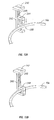
- second arm 246 is movably connected to attachment member 242 such that parking mechanism 240 is free to pivot, rotate, slide, or the like, between a first position ( FIG. 12A ) and at least one subsequent position ( FIG. 12B ). Movement of parking mechanism 240 between the first position and the at least one subsequent position may be facilitated through any suitable structural mechanism, e.g., a hinge or a pivot.
- parking mechanism 240 In the first position ( FIG. 12A ), parking mechanism 240 is oriented so as not to engage suture 216. In the at least one subsequent position ( FIG. 12B ), parking mechanism 240 is reconfigured to facilitate engagement with at least a portion, e.g. tail portion 216a, of suture 216, as described in further detail below.
- the parking mechanism may be operatively associated with a programmable control module, actuator, or the like, such that movement from the first position to the at least one subsequent position may be manually or automatically regulated.
- the attachment member may be fixedly attached to the apparatus such that the radial, lateral, or rotational movement of the parking mechanism is substantially prevented.
- the parking mechanism remains substantially stationary and, accordingly, does not transition between the first and second positions discussed above.
- Parking mechanism 240 includes respective first and second arms 244, 246.
- first arm 244 is movable in relation to second arm 246 such that parking mechanism 240 may transition between an open condition ( FIG. 13A ) and a closed condition ( FIG. 13B ), while second arm 246 is stationary.
- Second arm 246 includes a slot 248 defined therein that is configured and dimensioned to slidably receive a portion of first arm 244.
- first arm 244 is spaced apart from second arm 246 such that a space 250 is defined therebetween that is dimensioned to receive at least a portion of suture 216, e.g. tail portion 216a.
- First arm 244 is approximated relative to second arm 246 during an actuation sequence until first arm 244 substantially abuts second arm 246, thereby closing off space 250 in the closed condition, and releasably retaining tail portion 216a of suture 216 therein.
- the parking mechanism may be operatively connected to a programmable control module, actuator, or the like such that the transition from the open condition to the closed condition may be manually or automatically regulated.
- tail portion 216a of suture 216 in oriented and maintained in desired; pre-determined manner with respect to base member x defined by angle ⁇ , as discussed in further detail below.
- Angle ⁇ may be any angle substantially within the range of 0° to 180°.
- the present disclosure contemplates that both the first and second arms of the parking mechanism are movable. As the parking mechanism transitions from the open condition to the closed condition, the first and second arms approximate relative to one another.
- apparatus 200 also includes at least one positioning rod 260 that is extendable at least partially through an aperture 212 formed in base member 210 and retainer package 270.
- Positioning rod 260 includes a tip 262 and is movable from a first or retracted position, seen in FIG. 12A , in which tip 262 is substantially flush with or below base member 210, to a second or extended position, seen in FIG. 12B , in which positioning rod 260 is configured to engage tail portion 216a of suture 216.
- positioning rod 260 In the extended position, positioning rod 260 ensures that tail portion 216a remains in the pre-determined orientation, as discussed above, until assembly of the retainer package 270 is complete.
- the parking mechanism and the positioning rod cooperate to orient the tail portion of the suture within a perimeter of the retainer package.
- the positioning rods may be operatively connected to a programmable control module, actuator, or the like, such that the transition of the positioning rod between the first or retracted position and the second or extended position may be either manually or automatically regulated.
- a method of winding a suture 216 using apparatus 200 will be discussed.
- the method described hereinbelow is substantially identical to that which was discussed above, and will therefore not be repeated.
- parking mechanism 240 is in the first position ( FIG. 12A ) and in the open condition ( FIG. 12B ).
- parking mechanism 240 transitions both into the second position ( FIG. 12B ), so at to facilitate engagement with tail portion 216a of suture 216, and the closed condition ( FIG. 13B ), thereby releasably capturing tail portion 216a within space 250.
- positioning rod 260 is extended from the retracted position ( FIG. 12A ), such that tip 262 extends at least partially beyond base 210, thereby facilitating engagement of positioning rod 260 with tail portion 216a of suture 216.
- positioning rod 260 cooperates with parking mechanism 240 to configure tail portion 216a of suture 216 in the pre-determined orientation, as discussed above.
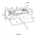
- Suture winding device 300 includes a base 310 that is rotatably mounted to a plate 301.
- Holder 30, that was discussed in detail previously with reference to FIGS. 3-4 , is rotatably mounted to plate 301.
- Base 310 is a generally elliptical structure that includes a frame 318 and a plate 319 that is attached to a mounting surface 326 of frame 318.
- a mounting member 307 is disposed atop plate 319 and provides a surface suitable for positioning a first member 372 of a retainer.
- Mounting member 307 includes needle holder 50 as previously shown and described with reference to FIG. 2 .
- needle 14 has a quantity of suture 16 attached thereto and is disposed in needle holder 50. A portion of suture 16 extends beyond base 310 and is threaded through first and second arms 32, 34 of holder 30.
- Suture winding device 300 includes a plurality of rods 322 that is extendable through throughholes 376 of first member 372 where each rod 322 includes a tip 323.
- rods 322 are positionable between a first or retracted position and a second or extended position as shown in FIGS. 14A-14C .
- the suture winding device may include a programmable control module, an actuator, or the like, operatively connected to the rods such that the transition between the first or retracted position and the second or extended position may be either manually or automatically regulated.
- rods 322 When in the extended position, rods 322 are capable of forming one or more loops of suture 16 as will be discussed in detail hereinbelow.
- tips 323 of rods 322 are substantially flush with a top surface of mounting member 307.
- tips 323 may exist below the top surface of mounting member 307.
- rods 322 are arranged in one or more arrays 330.
- Each array 330 includes a plurality of rods 322 that are arranged in one or more arcs 340 of rods 322.
- the arrays 330 are spaced apart along a longitudinal axis of base 310. Similar to suture winding device 300, arrays 330 are spaced apart about needle holder 50.
- Needle holder 50 is releasably mounted in mounting member 307 such that a top surface of plate 52 is substantially flush with the top surface of mounting member 307.
- needle holder 50 may be replaced by alternate embodiments of the needle holder that are configured to receive single needles, double needles, or needles of varying diameters and dimensions regardless of whether the needles are in a single or double configuration.
- each array 330 includes an arc 340 of rods 322. Additional arcs 340 are illustrated in FIGS. 14B-14C .
- each array 330 includes two arcs (340a, 340b) while FIG. 14C illustrates suture winding device 300 with three arcs (340a, 340b, 340c) in each array 330.
- the spatial arrangement and relationship of rods 322, arrays 330, and arcs 340 will now be discussed in further detail. Moving from needle holder 50 towards an outer edge of mounting member 307, arcs 340 have successively larger radii such that rods 322 in arc 340a (i.e.
- arc 340c is spaced further away from needle holder 50 than arc 340b and has a larger radii than arc 340b or 340a such that rods 322 in arc 340c are spaced further apart than rods 322 in arc 340a or 340b.
- the radius of each arc increases as each arc is spaced further away from needle holder 50 towards the outer edge of mounting member 307 thereby increasing the distance between rods 322 in each arc.
- rods 322 are positionable between a retracted position and an extended position. Each rod 322 may be independently positionable. In one embodiment, rods 322 in each arc (340a, 340b, or 340c) are positionable as a group such that all rods 322 in each arc (340a, 340b, or 340c) move substantially simultaneously. In addition, in embodiments having two arrays 330, arcs may be positioned sequentially such that rods 322 in arc 340a are moved substantially in unison from the retracted state to the extended state or vice versa. Furthermore, additional arcs 340b, 340c are positioned similarly such that corresponding arcs in each array 330 (i.e. arc pairs 340a, 340a or 340b, 340b or 340c, 340c) are moved substantially simultaneously.
- Operative force to transition rods 322 from the retracted to the extended position or the extended to the retracted position may be supplied by mechanical, hydraulic, pneumatic, or electric sources as are well known to those of skill in the art.
- rods 322 are transitioned from their positions using a number of cams and/or levers.
- hydraulic force supplied by water or oil, pneumatic force supplied by air or other compressed gasses, or electric force supplied by motors or solenoids may be substituted for or combined with the cams and/or levers.
- each array 330 has rods 322 of arc 340a in their extended position.
- One or more needles 14 having a quantity of suture 16 attached thereto is positioned in needle holder 50 as discussed in detail above with reference to FIG. 5 and first member 372 is placed on mounting member 307 such that rods 322 in the extended position align with throughholes 376. Since rods 322 and throughholes 376 are configured for slidably engaging one another, a slight amount of downward force is required to position first member 372 in contact with the top surface of mounting member 307.
- Suture 16 extends through.slot 378 of first member 372 such that it is accessible from an outside region. Subsequently, suture 16 is positioned such that a portion of suture 16 contacts one or more of rods 322 in arc 340a.
- Suture 16 is then placed between first and second arms 32, 34 of holder 30 while first arm 32 is in the first state ( FIG. 3 ).
- the actuator is energized by the selected power source (i.e. pneumatic, hydraulic, or electric) to transition first arm 34 from the first state to the second state (i.e. towards second arm 34) and slidably capturing a portion of suture 16 therebetween.
- the selected power source i.e. pneumatic, hydraulic, or electric
- Base 310 is rotated on plate 301 such that a desired quantity of suture 16 is wound about rods 322 in arcs 340a forming loops of suture 16 ( FIG. 14A ).
- rods 322 in arcs 340b may be transitioned to their extended position ( FIG. 14B ) while base 310 continues to rotate on plate 301 and rods 322 in arcs 340a remain in their extended position.
- rods 322 of arcs 340b are transitioned to their extended positions, suture 16 now forms loops only about arcs 340b without forming additional loops about arcs 340a.
- rods 322 in arcs 340c may be transitioned to their extended position ( FIG. 14C ) while base 310 continues to rotate. As base 310 rotates, one or more loops of suture 16 are only formed about arcs 340c without forming additional loops about arcs 340a or 340b. While loops of suture 16 are forming about arcs 340c, rods 322 in arcs 340a and 340b remain in their extended position maintaining the previously formed loops of suture 16.
- first member 72 After a desired quantity of suture 16 is disposed on first member 72, rotation of base 310 is halted. Holder 30 is then positioned from its loading position shown in FIG. 14A to its unloading position in FIG. 14C . By maintaining suture 16 between arms 32 and 34 of holder 30 as it transitions from its loading position to its unloading position, a desired amount of tension is maintained on suture 16 prior to forming retainer 70.
- the desired quantity of suture 16 that is disposed on first member 372 may then be separated from the source of suture 16 by cutting or other techniques known in the art. The separated end of suture 16 is positioned along the top surface of first member 372 prior to placing a second member of retainer atop first member 372 similar to the formation of retainer 70 in the previously discussed embodiment.
- Joinder and formation of retainer 70 is substantially similar to that of the previous embodiment using pressure and/or thermal energy from heat stake apparatus 110 as illustrated in FIGS. 9-11 and discussed previously.
- holder 30 is attached to a rail assembly 400 as shown in FIGS. 14-15 .
- Holder 30 was previously described with reference to FIGS. 3-4 .
- holder 30 is positionable on rail assembly 400 rather than being rotatably mounted to plate 1 using mounting arm 42 as in the previous embodiment.
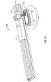
- Rail assembly 400 includes a carriage 410 that is slidably mounted to rail 420 using structures and techniques known to those of skill in the art.
- Holder 30 is attached to carriage 410 thereby allowing holder 30 to be positioned along rail 420 throughout a plurality of positions including a loading position ( FIG. 15 ) and an unloading position ( FIG. 16 ).
- Holder 30 and rail assembly 400 are adapted for use with any of the embodiments disclosed herein, i.e. suture winding device 100 is shown in FIGS. 15-16 for illustrative purposes only.
- suture 16 As suture 16 is wound onto suture winding device 100, as previously shown and described, carriage 410 and holder 30 move along rail 420 from the loading position to the unloading position. Movement of carriage 410 is coordinated and synchronized with the rotation of suture winding device 100 such that the desired amount of tension is maintained on suture 16 during the winding process. After the desired amount of suture 16 is wound onto suture winding device 100 (i.e. holder 30 is in the unloading position), suture 16 may be separated as discussed previously with reference to suture winding device 100.
- joinder and formation of retainer 70 is substantially similar to that of the previous embodiment using pressure and/or thermal energy from heat stake apparatus 110 as illustrated in FIGS. 9-11 and discussed previously.
Landscapes
- Health & Medical Sciences (AREA)
- Life Sciences & Earth Sciences (AREA)
- Surgery (AREA)
- Heart & Thoracic Surgery (AREA)
- Engineering & Computer Science (AREA)
- Biomedical Technology (AREA)
- Nuclear Medicine, Radiotherapy & Molecular Imaging (AREA)
- Medical Informatics (AREA)
- Molecular Biology (AREA)
- Animal Behavior & Ethology (AREA)
- General Health & Medical Sciences (AREA)
- Public Health (AREA)
- Veterinary Medicine (AREA)
- Dentistry (AREA)
- Surgical Instruments (AREA)
Applications Claiming Priority (1)
| Application Number | Priority Date | Filing Date | Title |
|---|---|---|---|
| US11/809,081 US7694489B2 (en) | 2005-03-11 | 2007-05-31 | Suture winding device |
Publications (3)
| Publication Number | Publication Date |
|---|---|
| EP1997437A2 true EP1997437A2 (de) | 2008-12-03 |
| EP1997437A3 EP1997437A3 (de) | 2009-04-01 |
| EP1997437B1 EP1997437B1 (de) | 2011-02-02 |
Family
ID=39689063
Family Applications (1)
| Application Number | Title | Priority Date | Filing Date |
|---|---|---|---|
| EP08251863A Not-in-force EP1997437B1 (de) | 2007-05-31 | 2008-05-29 | Wundnahtwickelvorrichtung und Verfahren zu ihrer Anwendung |
Country Status (8)
| Country | Link |
|---|---|
| US (4) | US7694489B2 (de) |
| EP (1) | EP1997437B1 (de) |
| JP (2) | JP2008296017A (de) |
| CN (1) | CN101313863B (de) |
| AU (1) | AU2008202093B2 (de) |
| CA (1) | CA2630005C (de) |
| DE (1) | DE602008004801D1 (de) |
| ES (1) | ES2359363T3 (de) |
Cited By (1)
| Publication number | Priority date | Publication date | Assignee | Title |
|---|---|---|---|---|
| US20230255622A1 (en) * | 2021-06-08 | 2023-08-17 | George Swope MUNDAY | Apparatus for closing a surgical site |
Families Citing this family (42)
| Publication number | Priority date | Publication date | Assignee | Title |
|---|---|---|---|---|
| US7694489B2 (en) * | 2005-03-11 | 2010-04-13 | Tyco Healthcare Group Lp | Suture winding device |
| US11812951B2 (en) | 2008-06-17 | 2023-11-14 | Apollo Endosurgery Us, Inc. | Endoscopic needle assembly |
| US8679136B2 (en) | 2008-06-17 | 2014-03-25 | Apollo Endosurgery, Inc. | Needle capture device |
| ES2734905T3 (es) | 2008-06-17 | 2019-12-12 | Apollo Endosurgery Inc | Sistema de sutura endoscópica |
| US9486126B2 (en) | 2008-06-17 | 2016-11-08 | Apollo Endosurgery, Inc. | Endoscopic helix tissue grasping device |
| US12108939B2 (en) | 2008-06-17 | 2024-10-08 | Boston Scientific Scimed, Inc. | Endoscopic tissue grasping systems and methods |
| DK2153780T3 (da) * | 2008-08-14 | 2014-10-06 | Braun Surgical S A B | Bæreorgan til kirurgisk suturmateriale, som er forbundet med mindst en nål |
| USD630325S1 (en) * | 2009-08-20 | 2011-01-04 | Tyco Healthcare Group Lp | Suture package |
| US8573391B2 (en) * | 2010-03-08 | 2013-11-05 | Ethicon, Inc. | Suture packages providing unconstrained dispensing of sutures and methods therefor |
| US10805331B2 (en) | 2010-09-24 | 2020-10-13 | BitSight Technologies, Inc. | Information technology security assessment system |
| US9438615B2 (en) | 2013-09-09 | 2016-09-06 | BitSight Technologies, Inc. | Security risk management |
| USD733295S1 (en) | 2014-03-27 | 2015-06-30 | Surgical Specialties Corporation | Two tab suture dispensing card |
| USD733296S1 (en) * | 2014-03-27 | 2015-06-30 | Surgical Specialties Corporation | Arm with wrapping fixture posts |
| USD744648S1 (en) | 2014-07-08 | 2015-12-01 | Surgical Specialties Corporation | Suture dispensing card |
| US9908655B2 (en) * | 2015-04-29 | 2018-03-06 | Ethicon, Inc. | Stylus winding fixture for winding surgical sutures and method of winding a suture |
| CN105232333B (zh) * | 2015-09-02 | 2019-01-29 | 宁波市镇海区精量农业科技开发有限公司 | 铁皮枫斗成型机 |
| US11141147B2 (en) | 2016-08-10 | 2021-10-12 | Apollo Endosurgery Us, Inc. | Endoscopic suturing system having external instrument channel |
| US11051800B2 (en) | 2016-08-10 | 2021-07-06 | Apollo Endosurgery Us, Inc. | Endoscopic suturing system having external instrument channel |
| US20180235625A1 (en) * | 2017-02-17 | 2018-08-23 | Ethicon Llc | End effector with adjunct materials |
| US10425380B2 (en) | 2017-06-22 | 2019-09-24 | BitSight Technologies, Inc. | Methods for mapping IP addresses and domains to organizations using user activity data |
| EP3438029B1 (de) * | 2017-08-01 | 2019-11-20 | Harro Höfliger Verpackungsmaschinen GmbH | Universelle wickelmaschine für eine vielzahl von ablagenentwürfen |
| US10257219B1 (en) | 2018-03-12 | 2019-04-09 | BitSight Technologies, Inc. | Correlated risk in cybersecurity |
| GB201804141D0 (en) * | 2018-03-15 | 2018-05-02 | Univ Of Hull | Suture thread |
| US10812520B2 (en) | 2018-04-17 | 2020-10-20 | BitSight Technologies, Inc. | Systems and methods for external detection of misconfigured systems |
| US11200323B2 (en) | 2018-10-17 | 2021-12-14 | BitSight Technologies, Inc. | Systems and methods for forecasting cybersecurity ratings based on event-rate scenarios |
| US10521583B1 (en) | 2018-10-25 | 2019-12-31 | BitSight Technologies, Inc. | Systems and methods for remote detection of software through browser webinjects |
| EP3725718B1 (de) * | 2019-04-18 | 2021-09-08 | Harro Höfliger Verpackungsmaschinen GmbH | Wickelkopf für chirurgisches nahtmaterial |
| WO2020219791A1 (en) * | 2019-04-24 | 2020-10-29 | Lsi Solutions, Inc. | Suture security device for minimally invasive surgical suturing |
| US10726136B1 (en) | 2019-07-17 | 2020-07-28 | BitSight Technologies, Inc. | Systems and methods for generating security improvement plans for entities |
| US11956265B2 (en) | 2019-08-23 | 2024-04-09 | BitSight Technologies, Inc. | Systems and methods for inferring entity relationships via network communications of users or user devices |
| US10848382B1 (en) | 2019-09-26 | 2020-11-24 | BitSight Technologies, Inc. | Systems and methods for network asset discovery and association thereof with entities |
| US11032244B2 (en) | 2019-09-30 | 2021-06-08 | BitSight Technologies, Inc. | Systems and methods for determining asset importance in security risk management |
| US10791140B1 (en) | 2020-01-29 | 2020-09-29 | BitSight Technologies, Inc. | Systems and methods for assessing cybersecurity state of entities based on computer network characterization |
| US10893067B1 (en) | 2020-01-31 | 2021-01-12 | BitSight Technologies, Inc. | Systems and methods for rapidly generating security ratings |
| US11023585B1 (en) | 2020-05-27 | 2021-06-01 | BitSight Technologies, Inc. | Systems and methods for managing cybersecurity alerts |
| US11122073B1 (en) | 2020-12-11 | 2021-09-14 | BitSight Technologies, Inc. | Systems and methods for cybersecurity risk mitigation and management |
| US12079347B2 (en) | 2021-03-31 | 2024-09-03 | BitSight Technologies, Inc. | Systems and methods for assessing cybersecurity risk in a work from home environment |
| US11701104B2 (en) * | 2021-06-08 | 2023-07-18 | George Swope MUNDAY | Apparatus for closing a surgical site |
| US12471911B2 (en) * | 2022-01-10 | 2025-11-18 | George Swope Munday | Apparatus for closing a surgical site |
| US12353563B2 (en) | 2021-07-01 | 2025-07-08 | BitSight Technologies, Inc. | Systems and methods for accelerating cybersecurity assessments |
| US12425437B2 (en) | 2021-09-17 | 2025-09-23 | BitSight Technologies, Inc. | Systems and methods for precomputation of digital asset inventories |
| US12282564B2 (en) | 2022-01-31 | 2025-04-22 | BitSight Technologies, Inc. | Systems and methods for assessment of cyber resilience |
Citations (4)
| Publication number | Priority date | Publication date | Assignee | Title |
|---|---|---|---|---|
| US5123528A (en) | 1991-01-07 | 1992-06-23 | United States Surgical Corporation | Package for needle sutures or the like |
| US5473854A (en) | 1994-01-13 | 1995-12-12 | Ethicon, Inc. | Machine for the automated packaging of needles and attached sutures and method of utilizing the packaging machine |
| US20050035007A1 (en) | 2003-07-18 | 2005-02-17 | Jack Kennedy | Suture packaging |
| US20060201828A1 (en) | 2005-03-11 | 2006-09-14 | Tyco Healthcare Group Lp | Suture winding device and methods of use thereof |
Family Cites Families (19)
| Publication number | Priority date | Publication date | Assignee | Title |
|---|---|---|---|---|
| US5179818A (en) | 1988-08-24 | 1993-01-19 | Ethicon, Inc. | Oval wrap suture package |
| CN2127300Y (zh) * | 1992-08-25 | 1993-02-24 | 陈利 | 医用手术用线绕线机 |
| US5368599A (en) | 1992-10-08 | 1994-11-29 | United States Surgical Corporation | Surgical fastening apparatus with suture array |
| BR9301757A (pt) | 1993-05-05 | 1994-11-29 | Johnson & Johnson Produtos Pro | Embalagem dobrável para produtos cirúrgicos |
| US5491954A (en) | 1994-01-13 | 1996-02-20 | Ethicon, Inc. | Suture winder machine |
| US5487216A (en) | 1994-01-13 | 1996-01-30 | Ethicon, Inc. | Control system for an automatic needle-suture assembly and packaging machine |
| US5388599A (en) * | 1994-01-13 | 1995-02-14 | Yen; Lung W. | Retractable toothbrush and toothpaste holder |
| US5667155A (en) | 1994-04-04 | 1997-09-16 | Ethicon, Inc. | Suture dispenser winding fixture |
| EP0676172B1 (de) | 1994-04-04 | 1998-08-05 | Ethicon, Inc. | Nahtmaterialverpackung und Verfahren zum Wickeln des Nahtmaterials in die Verpackung |
| US5628395A (en) * | 1995-06-23 | 1997-05-13 | Ethicon, Inc. | Suture tray package having grooved winding surface |
| US5695138A (en) | 1996-09-03 | 1997-12-09 | Ethicon, Inc. | Winding fixture for surgical suture package |
| BR9703513A (pt) * | 1997-06-10 | 1999-01-05 | Johnson & Johnson Produtos Pro | Distribuidor de suturas cirúrgicas e processo de enrolamento de sutura cirúrgica |
| US6138440A (en) | 1998-03-06 | 2000-10-31 | United States Surgical Corporation | Surgical suture retainer package |
| US20030003507A1 (en) * | 1999-06-02 | 2003-01-02 | Genentech, Inc. | Compositions and methods for the diagnosis and treatment of tumor |
| US6283297B1 (en) | 2000-04-20 | 2001-09-04 | Marie E. Mosley | Method and apparatus for organizing threads |
| US6463719B2 (en) | 2000-12-13 | 2002-10-15 | Ethicon | Suture winding machine, suture tray package, and method of winding sutures |
| US6804937B2 (en) * | 2003-03-13 | 2004-10-19 | Ethicon, Inc. | Package winding machine |
| EP1633321A4 (de) * | 2003-06-18 | 2006-11-02 | Onyx Pharma Inc | Verfahren zur reinigung von virus |
| US7694489B2 (en) * | 2005-03-11 | 2010-04-13 | Tyco Healthcare Group Lp | Suture winding device |
-
2007
- 2007-05-31 US US11/809,081 patent/US7694489B2/en active Active
- 2007-12-14 US US12/002,254 patent/US7665279B2/en active Active
-
2008
- 2008-04-25 CA CA2630005A patent/CA2630005C/en not_active Expired - Fee Related
- 2008-05-12 AU AU2008202093A patent/AU2008202093B2/en not_active Ceased
- 2008-05-28 JP JP2008139872A patent/JP2008296017A/ja not_active Withdrawn
- 2008-05-29 ES ES08251863T patent/ES2359363T3/es active Active
- 2008-05-29 EP EP08251863A patent/EP1997437B1/de not_active Not-in-force
- 2008-05-29 DE DE602008004801T patent/DE602008004801D1/de active Active
- 2008-05-30 CN CN2008101086644A patent/CN101313863B/zh active Active
-
2010
- 2010-02-02 US US12/698,205 patent/US7921623B2/en not_active Expired - Lifetime
-
2011
- 2011-03-18 US US13/051,448 patent/US8122688B2/en not_active Expired - Lifetime
-
2013
- 2013-06-07 JP JP2013120524A patent/JP5680707B2/ja not_active Expired - Fee Related
Patent Citations (4)
| Publication number | Priority date | Publication date | Assignee | Title |
|---|---|---|---|---|
| US5123528A (en) | 1991-01-07 | 1992-06-23 | United States Surgical Corporation | Package for needle sutures or the like |
| US5473854A (en) | 1994-01-13 | 1995-12-12 | Ethicon, Inc. | Machine for the automated packaging of needles and attached sutures and method of utilizing the packaging machine |
| US20050035007A1 (en) | 2003-07-18 | 2005-02-17 | Jack Kennedy | Suture packaging |
| US20060201828A1 (en) | 2005-03-11 | 2006-09-14 | Tyco Healthcare Group Lp | Suture winding device and methods of use thereof |
Cited By (2)
| Publication number | Priority date | Publication date | Assignee | Title |
|---|---|---|---|---|
| US20230255622A1 (en) * | 2021-06-08 | 2023-08-17 | George Swope MUNDAY | Apparatus for closing a surgical site |
| US11937807B2 (en) * | 2021-06-08 | 2024-03-26 | George Swope MUNDAY | Apparatus for closing a surgical site |
Also Published As
| Publication number | Publication date |
|---|---|
| US20080093231A1 (en) | 2008-04-24 |
| US8122688B2 (en) | 2012-02-28 |
| ES2359363T3 (es) | 2011-05-20 |
| US20100132306A1 (en) | 2010-06-03 |
| CN101313863B (zh) | 2012-09-05 |
| US20110162324A1 (en) | 2011-07-07 |
| AU2008202093B2 (en) | 2012-12-06 |
| CA2630005A1 (en) | 2008-11-30 |
| CN101313863A (zh) | 2008-12-03 |
| AU2008202093A1 (en) | 2008-12-18 |
| JP2008296017A (ja) | 2008-12-11 |
| JP5680707B2 (ja) | 2015-03-04 |
| US20080017526A1 (en) | 2008-01-24 |
| US7921623B2 (en) | 2011-04-12 |
| DE602008004801D1 (de) | 2011-03-17 |
| EP1997437B1 (de) | 2011-02-02 |
| JP2013173023A (ja) | 2013-09-05 |
| US7694489B2 (en) | 2010-04-13 |
| US7665279B2 (en) | 2010-02-23 |
| CA2630005C (en) | 2015-10-06 |
| EP1997437A3 (de) | 2009-04-01 |
Similar Documents
| Publication | Publication Date | Title |
|---|---|---|
| EP1997437B1 (de) | Wundnahtwickelvorrichtung und Verfahren zu ihrer Anwendung | |
| JP2011218197A (ja) | 縫合糸巻き取りデバイスおよびその使用の方法 | |
| US10278693B2 (en) | System and method for forming barbs on a suture | |
| AU2013201329B2 (en) | Suture winding device and methods of use thereof | |
| AU2011239214B2 (en) | Suture winding device and methods of use thereof | |
| CN119304943B (zh) | 一种医用缝合线倒刺激光辅助裁剪设备 | |
| CN120221264B (zh) | 贴片式电子元件绕线机及绕线方法 | |
| CN118948446A (zh) | 缝合机器人 | |
| CN121084728A (zh) | 一种医用缝合线全自动绕线封装设备 |
Legal Events
| Date | Code | Title | Description |
|---|---|---|---|
| PUAI | Public reference made under article 153(3) epc to a published international application that has entered the european phase |
Free format text: ORIGINAL CODE: 0009012 |
|
| AK | Designated contracting states |
Kind code of ref document: A2 Designated state(s): AT BE BG CH CY CZ DE DK EE ES FI FR GB GR HR HU IE IS IT LI LT LU LV MC MT NL NO PL PT RO SE SI SK TR |
|
| AX | Request for extension of the european patent |
Extension state: AL BA MK RS |
|
| PUAL | Search report despatched |
Free format text: ORIGINAL CODE: 0009013 |
|
| AK | Designated contracting states |
Kind code of ref document: A3 Designated state(s): AT BE BG CH CY CZ DE DK EE ES FI FR GB GR HR HU IE IS IT LI LT LU LV MC MT NL NO PL PT RO SE SI SK TR |
|
| AX | Request for extension of the european patent |
Extension state: AL BA MK RS |
|
| 17P | Request for examination filed |
Effective date: 20090903 |
|
| 17Q | First examination report despatched |
Effective date: 20091111 |
|
| AKX | Designation fees paid |
Designated state(s): DE ES FR GB IE IT |
|
| GRAP | Despatch of communication of intention to grant a patent |
Free format text: ORIGINAL CODE: EPIDOSNIGR1 |
|
| GRAS | Grant fee paid |
Free format text: ORIGINAL CODE: EPIDOSNIGR3 |
|
| GRAA | (expected) grant |
Free format text: ORIGINAL CODE: 0009210 |
|
| AK | Designated contracting states |
Kind code of ref document: B1 Designated state(s): DE ES FR GB IE IT |
|
| REG | Reference to a national code |
Ref country code: GB Ref legal event code: FG4D |
|
| REG | Reference to a national code |
Ref country code: IE Ref legal event code: FG4D |
|
| REF | Corresponds to: |
Ref document number: 602008004801 Country of ref document: DE Date of ref document: 20110317 Kind code of ref document: P |
|
| REG | Reference to a national code |
Ref country code: DE Ref legal event code: R096 Ref document number: 602008004801 Country of ref document: DE Effective date: 20110317 |
|
| REG | Reference to a national code |
Ref country code: ES Ref legal event code: FG2A Ref document number: 2359363 Country of ref document: ES Kind code of ref document: T3 Effective date: 20110520 |
|
| PLBE | No opposition filed within time limit |
Free format text: ORIGINAL CODE: 0009261 |
|
| STAA | Information on the status of an ep patent application or granted ep patent |
Free format text: STATUS: NO OPPOSITION FILED WITHIN TIME LIMIT |
|
| 26N | No opposition filed |
Effective date: 20111103 |
|
| REG | Reference to a national code |
Ref country code: DE Ref legal event code: R097 Ref document number: 602008004801 Country of ref document: DE Effective date: 20111103 |
|
| PGFP | Annual fee paid to national office [announced via postgrant information from national office to epo] |
Ref country code: ES Payment date: 20120528 Year of fee payment: 5 |
|
| PGFP | Annual fee paid to national office [announced via postgrant information from national office to epo] |
Ref country code: IT Payment date: 20141127 Year of fee payment: 7 |
|
| REG | Reference to a national code |
Ref country code: FR Ref legal event code: PLFP Year of fee payment: 8 |
|
| REG | Reference to a national code |
Ref country code: ES Ref legal event code: FD2A Effective date: 20151030 |
|
| PG25 | Lapsed in a contracting state [announced via postgrant information from national office to epo] |
Ref country code: IT Free format text: LAPSE BECAUSE OF NON-PAYMENT OF DUE FEES Effective date: 20150529 |
|
| PG25 | Lapsed in a contracting state [announced via postgrant information from national office to epo] |
Ref country code: ES Free format text: LAPSE BECAUSE OF NON-PAYMENT OF DUE FEES Effective date: 20140530 |
|
| REG | Reference to a national code |
Ref country code: FR Ref legal event code: PLFP Year of fee payment: 9 |
|
| REG | Reference to a national code |
Ref country code: FR Ref legal event code: PLFP Year of fee payment: 10 |
|
| REG | Reference to a national code |
Ref country code: FR Ref legal event code: PLFP Year of fee payment: 11 |
|
| PGFP | Annual fee paid to national office [announced via postgrant information from national office to epo] |
Ref country code: GB Payment date: 20200423 Year of fee payment: 13 |
|
| PGFP | Annual fee paid to national office [announced via postgrant information from national office to epo] |
Ref country code: IE Payment date: 20210422 Year of fee payment: 14 |
|
| GBPC | Gb: european patent ceased through non-payment of renewal fee |
Effective date: 20210529 |
|
| PG25 | Lapsed in a contracting state [announced via postgrant information from national office to epo] |
Ref country code: GB Free format text: LAPSE BECAUSE OF NON-PAYMENT OF DUE FEES Effective date: 20210529 |
|
| PG25 | Lapsed in a contracting state [announced via postgrant information from national office to epo] |
Ref country code: IE Free format text: LAPSE BECAUSE OF NON-PAYMENT OF DUE FEES Effective date: 20220529 |
|
| PGFP | Annual fee paid to national office [announced via postgrant information from national office to epo] |
Ref country code: DE Payment date: 20240418 Year of fee payment: 17 |
|
| PGFP | Annual fee paid to national office [announced via postgrant information from national office to epo] |
Ref country code: FR Payment date: 20240418 Year of fee payment: 17 |
|
| REG | Reference to a national code |
Ref country code: DE Ref legal event code: R119 Ref document number: 602008004801 Country of ref document: DE |
|
| PG25 | Lapsed in a contracting state [announced via postgrant information from national office to epo] |
Ref country code: DE Free format text: LAPSE BECAUSE OF NON-PAYMENT OF DUE FEES Effective date: 20251202 |
|
| PG25 | Lapsed in a contracting state [announced via postgrant information from national office to epo] |
Ref country code: FR Free format text: LAPSE BECAUSE OF NON-PAYMENT OF DUE FEES Effective date: 20250531 |