EP1997416A2 - Flexible hose and vacuum cleaner having the same - Google Patents
Flexible hose and vacuum cleaner having the same Download PDFInfo
- Publication number
- EP1997416A2 EP1997416A2 EP08003761A EP08003761A EP1997416A2 EP 1997416 A2 EP1997416 A2 EP 1997416A2 EP 08003761 A EP08003761 A EP 08003761A EP 08003761 A EP08003761 A EP 08003761A EP 1997416 A2 EP1997416 A2 EP 1997416A2
- Authority
- EP
- European Patent Office
- Prior art keywords
- hose
- pleats
- flexible hose
- circumferential surface
- outer circumferential
- Prior art date
- Legal status (The legal status is an assumption and is not a legal conclusion. Google has not performed a legal analysis and makes no representation as to the accuracy of the status listed.)
- Withdrawn
Links
Images




Classifications
-
- A—HUMAN NECESSITIES
- A47—FURNITURE; DOMESTIC ARTICLES OR APPLIANCES; COFFEE MILLS; SPICE MILLS; SUCTION CLEANERS IN GENERAL
- A47L—DOMESTIC WASHING OR CLEANING; SUCTION CLEANERS IN GENERAL
- A47L9/00—Details or accessories of suction cleaners, e.g. mechanical means for controlling the suction or for effecting pulsating action; Storing devices specially adapted to suction cleaners or parts thereof; Carrying-vehicles specially adapted for suction cleaners
- A47L9/24—Hoses or pipes; Hose or pipe couplings
- A47L9/248—Parts, details or accessories of hoses or pipes
-
- A—HUMAN NECESSITIES
- A47—FURNITURE; DOMESTIC ARTICLES OR APPLIANCES; COFFEE MILLS; SPICE MILLS; SUCTION CLEANERS IN GENERAL
- A47L—DOMESTIC WASHING OR CLEANING; SUCTION CLEANERS IN GENERAL
- A47L9/00—Details or accessories of suction cleaners, e.g. mechanical means for controlling the suction or for effecting pulsating action; Storing devices specially adapted to suction cleaners or parts thereof; Carrying-vehicles specially adapted for suction cleaners
- A47L9/0081—Means for exhaust-air diffusion; Means for sound or vibration damping
-
- A—HUMAN NECESSITIES
- A47—FURNITURE; DOMESTIC ARTICLES OR APPLIANCES; COFFEE MILLS; SPICE MILLS; SUCTION CLEANERS IN GENERAL
- A47L—DOMESTIC WASHING OR CLEANING; SUCTION CLEANERS IN GENERAL
- A47L9/00—Details or accessories of suction cleaners, e.g. mechanical means for controlling the suction or for effecting pulsating action; Storing devices specially adapted to suction cleaners or parts thereof; Carrying-vehicles specially adapted for suction cleaners
- A47L9/24—Hoses or pipes; Hose or pipe couplings
-
- F—MECHANICAL ENGINEERING; LIGHTING; HEATING; WEAPONS; BLASTING
- F16—ENGINEERING ELEMENTS AND UNITS; GENERAL MEASURES FOR PRODUCING AND MAINTAINING EFFECTIVE FUNCTIONING OF MACHINES OR INSTALLATIONS; THERMAL INSULATION IN GENERAL
- F16L—PIPES; JOINTS OR FITTINGS FOR PIPES; SUPPORTS FOR PIPES, CABLES OR PROTECTIVE TUBING; MEANS FOR THERMAL INSULATION IN GENERAL
- F16L11/00—Hoses, i.e. flexible pipes
- F16L11/04—Hoses, i.e. flexible pipes made of rubber or flexible plastics
- F16L11/11—Hoses, i.e. flexible pipes made of rubber or flexible plastics with corrugated wall
- F16L11/111—Hoses, i.e. flexible pipes made of rubber or flexible plastics with corrugated wall with homogeneous wall
Definitions
- the present invention relates to a flexible hose capable of being used in a vacuum cleaner and a vacuum cleaner having the same.
- a flexible hose is a hose that can be expanded and contracted within a predetermined range, and can be bent freely.
- Conventional flexible hoses have a plurality of pleats that project from an outer circumferential surface thereof so that the flexible hose can be expanded and contracted in a lengthwise direction thereof.
- Such hoses are often used in vacuum cleaners to connect a suction nozzle with a cleaner body.
- FIG. 1 illustrates a partial sectional view of a prior art flexible hose 1.
- the prior art flexible hose 1 has a plurality of pleats 13 formed on the outer circumferential surface of the hose body 11.
- Each of the pleats 13 is formed in a U shape. Both sides of the pleat 13 are formed to be substantially vertical with respect to the outer circumferential surface of the hose body 11.
- An inner space 13a of the pleat 13 is in fluid communication with the inside of the hose body 11.
- the plurality of pleats 13 allow the flexible hose 1 to be expanded and contracted within a predetermined range of sizes.
- FIG. 2 illustrates a second prior art flexible hose 2.
- the flexible hose 2 includes a hard steel wire 21 and a hose body 23.
- the hard steel wire 21 is formed in a helical shape, such as a coil spring, and the hose body 23 is formed of a composite resin film to cover the hard steel wire 21.
- Fold portions 25 are formed between pitches of the hard steel wire 21 on the hose body 23.
- the hard steel wire 21 and fold portions 25 allow the flexible hose 2 to be expanded and contracted in a lengthwise direction thereof.
- an aspect of the present invention is to provide a flexible hose that can reduce noise generated by air flowing inside thereof, to enhance the flexibility of the flexible hose, and to provide a vacuum cleaner having a flexible hose of the same characteristics.
- a flexible hose which includes a hose body having an inner passageway and an outer circumferential surface and a plurality of pleats formed on the outer circumferential surface of the hose body in predetermined intervals and adapted to give flexibility to and reduce noise within the flexible hose.
- At least one of the plurality of pleats may include an entering portion inclined with respect to the outer circumferential surface of the hose body, the entering portion being in fluid communication with the inner passageway of the hose body via the entering portion when in an open position, and the open portion being in an open position when the hose body is expanded lengthwise and in a closed position when the hose body is compressed lengthwise.
- a pair of sidewalls extends substantially vertical to the outer circumferential surface of the hose body and a head portion formed between the pair of sidewalls, the head portion being in fluid communication with the inner passageway of the hose body via the entering portion when the entering portion is in the open position and the head portion not being in fluid communication with the inner passageway of the hose body when the entering portion is in the closed position. Preventing fluid communication between the inner passageway and the head portions of the plurality of pleats in this way reduces noise caused by fluid flowing within the flexible hose.
- a sidewall of each of the plurality of pleats may be bent toward the inside of the pleat. Accordingly, the entering portions of the plurality of pleats can be opened or stretched significantly more than the pleats of conventional flexible hoses, thereby making the flexible hose more flexible.
- Each of the plurality of pleats may be a separate ring around the circumferential surface of the hose body.
- the plurality of pleats may be at least one pleat continuously connected across the length of the outer circumferential surface of the hose body in a substantially helical shape.
- At least one of the plurality of pleats in the first embodiment may comprise a pair of sidewalls extending substantially vertical to the outer circumferential surface of the hose body and an inner space formed between the pair of sidewalls, a first protrusion formed on one of the sidewalls, extending substantially parallel to the outer circumferential surface of the hose body, and a second protrusion formed on the opposite sidewall.
- the second protrusion is configured to be in sliding contact with the first protrusion such that when the first protrusion and second protrusion are in sliding contact the inner space of the pleat is not in fluid communication with the inner passageway. Preventing fluid communication between the inner passageway and the inner space of the plurality of pleats in this way reduces noise caused by air flowing within the flexible hose.
- This embodiment may also include at least two pleats that have different cross-sectional shapes from each other.
- a vacuum cleaner may include a cleaner body connected to a flexible hose of one of the above embodiments.
- the cleaner body suctions air towards the cleaner body and the flexible hose may be formed so that the entering portion of each of the plurality of pleats is inclined opposite to the direction air is suctioned into the cleaner body.
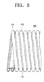
- FIG. 3 is a partial elevation view illustrating a flexible hose 100 according to an embodiment of the present invention
- FIG. 8 is a partial elevation view illustrating the flexible hose 100 according to another embodiment of the present invention.
- a flexible hose 100 includes a hose body 101 and a plurality of pleats 103.
- the hose body 101 forms an inner passage 104 through which a fluid, such as air, flows and the inner passage 104 has an approximately circular cross-section.
- the plurality of pleats 103 gives the flexible hose 100 flexibility and projects from the outer circumferential surface 102 of the hose body 101 in predetermined intervals.
- the plurality of pleats 103 allows the flexible hose 100 to be expanded and contracted within a predetermined range in a lengthwise direction of the flexible hose 101.
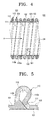
- the plurality of pleats 103 may have first pleats 110 and second pleats 120. Sections of the first pleat 110 and the second pleat 120 may have a different shape from each other, as illustrated in FIG. 4 .
- the first pleats 110 and the second pleats 120 are formed in repetition across the length of the hose body 101 by alternating between first pleats 110 and second pleats 120 at every pitch.
- each of the first pleats 110 may be formed so that one sidewall 110a thereof is bent toward an opposite sidewall 110b thereof. More specifically, each first pleat 110 may be formed with one sidewall 110a thereof bent inward, thereby having a cross-section formed substantially in the shape of the letter "R". Because the first pleats 110 have a substantially R-shaped cross-section, when the flexible hose 100 is expanded, both sidewalls 110a and 110b of the first pleat 110 can be separated to create a gap G 1 wider than that allowed by the parallel sidewalls of a conventional pleat. More specifically, each first pleat 110 with its substantially R-shaped cross-section enhances the flexibility of the flexible hose 100 beyond that of a conventional flexible hose.
- Each first pleat 110 has an entering portion 111 and a head portion 113.
- the entering portion 111 extends from the inner passage 104 through the hose body 101 to the head portion 113 at an incline with respect to the outer circumferential surface 102 of the hose body 101.
- the head portion 113 extends from the entering portion 111 substantially vertical with respect to the outer circumferential surface 102 of the hose body 101. Therefore, the head portion 113 of the first pleat 110 is in fluid communication with the inner passage 104 of the hose body 101 via the entering portion 111.
- the entering portion 111 may be inclined in a direction opposite to the direction in which air flows inside the hose body 101 (arrow A).
- each second pleat 120 may include a first protrusion 121 formed parallel to the outer circumferential surface 102 of the hose body 101 on one sidewall 120b of each of the second pleats 120, and a second protrusion 122 formed above the first protrusion 121 on an opposite sidewall 120a of the second pleat 120; wherein the second protrusion 122 is to be in sliding contact with the first protrusion 121.
- the first and second protrusions 121 and 122 move with respect to each other to allow an inner space 127 of the second pleat 120 to be opened or closed with respect to the inside of the hose body 101.
- the first and second protrusions 121 and 122 may be formed to block the inner space 127 of the second pleat 120 from fluidly communicating with the inside of the hose body 101.
- the flexible hose 100 having the above structure may be made of a resin with flexibility so that when the flexible hose 100 is pulled or pushed respectively in the lengthwise direction thereof, the flexible hose 100 expands or contracts. More specifically, when the flexible hose 100 is pushed in the lengthwise direction thereof, the hose body 101 is compressed lengthwise and the first gaps G 1 of the first pleats 110 and the second gaps G2 of the second pleats 120, illustrated in FIGS. 4 and 6 , close.
- the entering portion 111 closes and air flowing in the inner passage 104 of the hose body 101 cannot enter the head portions 113 of the first pleats 110
- the second gaps G2 of the second pleats 120 are closed, the front ends of the first protrusions 121 of the second pleats 120 contact the lower surfaces 125 of the opposite sidewalls 120a of the second pleats 120.
- the length of the flexible hose 100 can be contracted maximally as much as the sum of first gaps G 1 of the entering portions 111 of the first pleats 110 and second gaps G2 between the first protrusions 121 and the lower surface 125 of the opposite sidewalls 120a of the second pleats 120.
- the hose body 101 is expanded lengthwise and the first gaps G1 of the first pleats 110 and the second gaps G2 of the second pleats 120 open.
- the entering portion 111 opens and air flowing inside the hose body 101 can enter the head portions 113 of the first pleats 110.
- the second gaps G2 of the second pleats 120 are opened, the first and second protrusions 121 and 122 of the second pleats 120 prevent fluid from entering the inner spaces 127 of the second pleats 120, thereby minimizing noise generated by air flowing inside the flexible hose 100 even when the flexible hose 100 is expanded.
- the length of the flexible hose 100 can be expanded as much as the first gaps G 1 of the first pleats 110 and the second gaps G2 of the second pleats 120 open.
- a flexible hose 100 having a plurality of first pleats 110 and second pleats 120 increases the flexibility while minimizing the noise compared to a conventional flexible hose.
- the entering portion 111 of the first pleat 110 may be formed to be inclined in a direction opposite to the direction air flows through the flexible hose 100 (arrow A) so that noise can be minimized further.
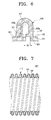
- FIG. 7 is a partial sectional view illustrating a flexible hose 100' according to another embodiment of the present invention.
- the flexible hose 100' includes a hose body 101' and a plurality of pleats 110'; wherein the plurality of pleats 110' are formed in a substantially helical shape on the outer circumferential surface 102' of the hose body 101' and has the same section as that of the first pleat 110 of the above-described embodiment. More specifically, the flexible hose 100' according to this embodiment is substantially the same as the flexible hose 100 according to the above-described embodiment, except that the plurality of pleats 110' are formed to have the same cross-sections. Therefore, structure and operation of the flexible hose 100' according to this embodiment will be omitted.
- flexible hose 100 and 100' respectively have a plurality of pleats 110, 120 and 110' formed in a substantially helical shape so that each of the plurality of pleats 110, 120 and 110' is continuously connected as one across the length of the flexible hose 100 and 100'.
- FIG. 8 illustrates a flexible hose 200 according to another embodiment of the present invention that may have a hose body 201 with a plurality of pleats 203 that are individually formed substantially in a ring shape on the hose body 201 such that each pleat is separated from each other pleat duplicately across the length of the hose body 201.
- the hose body 201 and the plurality of pleats 203 of the flexible hose 200 are substantially similar to the hose body 101 and the plurality of pleats 103 of the flexible hose 100 according to the above-described embodiment. Therefore, detailed descriptions of this embodiment will be omitted.
- FIG. 9 is a perspective view illustrating a vacuum cleaner 300 having the flexible hose 100 according to an embodiment of the present invention.
- the vacuum cleaner 300 having the flexible hose 100 according to an embodiment of the present invention includes a suction nozzle 310, an extension pipe 320, the flexible hose 100, and a cleaner body 340.
- the suction nozzle 310 has a contaminants suction opening (not illustrated) that faces a surface to be cleaned and draws in contaminants with air from the surface to be cleaned.
- the extension pipe 320 is connected with one side of the suction nozzle 310 to allow the contaminants and air drawn-in through the contaminants suction opening of the suction nozzle 310 to move toward the cleaner body 340.
- a handle 330 is provided at one end of the extension pipe 320 so that a user can grip the handle 330.
- the flexible hose 100 is disposed between the extension pipe 320 and the cleaner body 340 to allow the contaminants and air having passed through the extension pipe 320 to move toward the cleaner body 340.
- the flexible hose 100 is connected to the cleaner body 340 such that the entering portion 111 of the first pleat 110 of the flexible hose 100 is inclined to a direction opposite to the direction in which the air with contaminants flows through the flexible hose 100. More specifically, it is preferable that the flexible hose 100 is disposed between the extension pipe 320 and the cleaner body 340 so that the entering portion 111 of the first pleat 110 is inclined in a direction opposite to the direction fluid flows as arrow A through the flexible hose 100 as illustrated in an enlarged view of circle X in FIG. 9 .
- the entering portion 111 of the first pleat 110 of the flexible hose 100 is formed in a direction opposite to the flowing direction of the fluid, more specifically, the direction contaminants-laden air is being suctioned in, the noise generated by the air passing through the flexible hose 100 can be minimized.
- the cleaner body 340 includes a contaminant collecting apparatus (not illustrated) that separates contaminants from the air and collects the separated contaminants, and a vacuum generator (not illustrated) to generate a suction force for drawing in the contaminants with air.
- the contaminants suction opening of the suction nozzle 310 draws in contaminants from the surface to be cleaned.
- the drawn-in contaminants move to the contaminant collecting apparatus of the cleaner body 340 through the extension pipe 320 and the flexible hose 100.
- the first pleat 110 of the flexible hose 100 has the entering portion 111 that is inclined to a direction opposite to the flowing direction of the air passing through the flexible hose 100, the noise generated by the air passing through the flexible hose 100 is minimized.
- the noise generated by the air passing through the flexible hose 1 is approximately 69.4 dB.
- the noise generated in the flexible hose 100 by the air is approximately 68.9 dB.
- the noise generated the vacuum 300 is reduced by approximately 0.5 dB.
- the contaminant collecting apparatus separates contaminants from the drawn-in air, collects the separated contaminants, and then discharges cleaned air.
- the air discharged from the contaminant collecting apparatus passes through the vacuum generator, and then is exhausted to the outside of the cleaner body 340.
- the vacuum cleaner 300 is used merely as an example of one apparatus that can use the flexible hose 100 according to an embodiment of the present invention. However, this does not limit the kind of the apparatuses capable of using the flexible hose 100 according to an embodiment of the present invention.
- the flexible hose according to an embodiment of the present invention can prevent a fluid from entering the inner spaces of the plurality of pleats, the noise generated by the fluid passing through the flexible hose may be minimized.
- the flexible hose according to an embodiment of the present invention has the plurality of pleats, one sidewall of each of which is bent toward the inside of the pleat, enhances flexibility over prior art flexible hose having a plurality of pleats, both sidewalls of each of which are formed parallel to each other.
Landscapes
- Engineering & Computer Science (AREA)
- Mechanical Engineering (AREA)
- General Engineering & Computer Science (AREA)
- Electric Vacuum Cleaner (AREA)
- Rigid Pipes And Flexible Pipes (AREA)
- Electric Suction Cleaners (AREA)
Abstract
Description
- The present invention relates to a flexible hose capable of being used in a vacuum cleaner and a vacuum cleaner having the same.
- In general, a flexible hose is a hose that can be expanded and contracted within a predetermined range, and can be bent freely. Conventional flexible hoses have a plurality of pleats that project from an outer circumferential surface thereof so that the flexible hose can be expanded and contracted in a lengthwise direction thereof. Such hoses are often used in vacuum cleaners to connect a suction nozzle with a cleaner body.
-
FIG. 1 illustrates a partial sectional view of a prior artflexible hose 1. As seen inFIG. 1 , the prior artflexible hose 1 has a plurality ofpleats 13 formed on the outer circumferential surface of thehose body 11. Each of thepleats 13 is formed in a U shape. Both sides of thepleat 13 are formed to be substantially vertical with respect to the outer circumferential surface of thehose body 11. Aninner space 13a of thepleat 13 is in fluid communication with the inside of thehose body 11. The plurality ofpleats 13 allow theflexible hose 1 to be expanded and contracted within a predetermined range of sizes. - As illustrated in
FIG. 1 , when air flows inside of the flexible hose 1 (arrow A), some air enters theinner spaces 13a of the plurality of pleats 13 (arrow B). When air enters theinner spaces 13a of the plurality ofpleats 13, noise is increased. -
FIG. 2 illustrates a second prior artflexible hose 2. As seen inFIG. 2 , theflexible hose 2 includes ahard steel wire 21 and ahose body 23. Thehard steel wire 21 is formed in a helical shape, such as a coil spring, and thehose body 23 is formed of a composite resin film to cover thehard steel wire 21. Foldportions 25 are formed between pitches of thehard steel wire 21 on thehose body 23. Thehard steel wire 21 and foldportions 25 allow theflexible hose 2 to be expanded and contracted in a lengthwise direction thereof. - When the
flexible hose 2 is contracted,pleat spaces 27 are formed in a U shape between thefold portions 25 and thehard steel wire 21 positions in thepleat spaces 27. Therefore, when air flows inside theflexible hose 2, some air flows into thepleat spaces 27, which increases noise. Additionally, theflexible hose 2 ofFIG. 2 creates another problem in that thehard steel wire 21 adds significant weight to thehose 2. - Accordingly, an aspect of the present invention is to provide a flexible hose that can reduce noise generated by air flowing inside thereof, to enhance the flexibility of the flexible hose, and to provide a vacuum cleaner having a flexible hose of the same characteristics.
- In one embodiment, the above aspects and/or other features of the present invention are achieved by providing a flexible hose, which includes a hose body having an inner passageway and an outer circumferential surface and a plurality of pleats formed on the outer circumferential surface of the hose body in predetermined intervals and adapted to give flexibility to and reduce noise within the flexible hose. At least one of the plurality of pleats may include an entering portion inclined with respect to the outer circumferential surface of the hose body, the entering portion being in fluid communication with the inner passageway of the hose body via the entering portion when in an open position, and the open portion being in an open position when the hose body is expanded lengthwise and in a closed position when the hose body is compressed lengthwise. A pair of sidewalls extends substantially vertical to the outer circumferential surface of the hose body and a head portion formed between the pair of sidewalls, the head portion being in fluid communication with the inner passageway of the hose body via the entering portion when the entering portion is in the open position and the head portion not being in fluid communication with the inner passageway of the hose body when the entering portion is in the closed position. Preventing fluid communication between the inner passageway and the head portions of the plurality of pleats in this way reduces noise caused by fluid flowing within the flexible hose.
- A sidewall of each of the plurality of pleats may be bent toward the inside of the pleat. Accordingly, the entering portions of the plurality of pleats can be opened or stretched significantly more than the pleats of conventional flexible hoses, thereby making the flexible hose more flexible.
- Each of the plurality of pleats may be a separate ring around the circumferential surface of the hose body. Alternatively, the plurality of pleats may be at least one pleat continuously connected across the length of the outer circumferential surface of the hose body in a substantially helical shape.
- According to another embodiment of the present invention, at least one of the plurality of pleats in the first embodiment may comprise a pair of sidewalls extending substantially vertical to the outer circumferential surface of the hose body and an inner space formed between the pair of sidewalls, a first protrusion formed on one of the sidewalls, extending substantially parallel to the outer circumferential surface of the hose body, and a second protrusion formed on the opposite sidewall. The second protrusion is configured to be in sliding contact with the first protrusion such that when the first protrusion and second protrusion are in sliding contact the inner space of the pleat is not in fluid communication with the inner passageway. Preventing fluid communication between the inner passageway and the inner space of the plurality of pleats in this way reduces noise caused by air flowing within the flexible hose. This embodiment may also include at least two pleats that have different cross-sectional shapes from each other.
- According to yet another embodiment of the present invention, a vacuum cleaner may include a cleaner body connected to a flexible hose of one of the above embodiments. The cleaner body suctions air towards the cleaner body and the flexible hose may be formed so that the entering portion of each of the plurality of pleats is inclined opposite to the direction air is suctioned into the cleaner body.
- Other objects, advantages and salient features of the invention will become apparent from the following detailed description, which, taken in conjunction with the annexed drawings, discloses preferred embodiments of the invention.
- The above aspects and other aspects and/or advantages of the invention will be more apparent and more readily appreciated from the following description of the embodiments, taken in conjunction with the accompanying drawings in which like reference numerals refer to like parts, components and structures.
-
FIG. 1 is a partial longitudinal view in section illustrating a typical embodiment of a prior art flexible hose; -
FIG. 2 is a partial longitudinal view in part section and part elevation illustrating a second typical embodiment of prior art flexible hose; -
FIG. 3 is a partial side elevational view illustrating a flexible hose according to an embodiment of the present invention; -
FIG. 4 is a partial longitudinal view in section of the flexible hose illustrated inFIG. 1 ; -
FIG. 5 is a partial sectional view illustrating a first pleat of the flexible hose illustrated inFIG. 4 , showing the flexible hose compressed in a lengthwise direction; -
FIG. 6 is a partial sectional view illustrating a second pleat of the flexible hose illustrated inFIG. 4 , showing the flexible hose expanded in a lengthwise direction; -
FIG. 7 is a partial longitudinal view in section illustrating a flexible hose according to another embodiment of the present invention; -
FIG. 8 is a partial side elevation view illustrating a flexible hose according to another embodiment of the present invention; and -
FIG. 9 is a perspective view illustrating a vacuum cleaner having a flexible hose according to an embodiment of the present invention. - Hereinafter, certain exemplary embodiments of the present invention will be described in detail with reference to the accompanying drawings.
- The matters defined in the description, such as a detailed construction and elements thereof, are provided only to assist in a comprehensive understanding of the invention. Thus, it is apparent that the present invention may be carried out without such defined matters. Also, well-known functions or constructions are not described in detail to provide a clear and concise description of exemplary embodiments of the present invention.
-
FIG. 3 is a partial elevation view illustrating aflexible hose 100 according to an embodiment of the present invention, andFIG. 8 is a partial elevation view illustrating theflexible hose 100 according to another embodiment of the present invention. - Referring to
FIGS. 3 and4 , aflexible hose 100 according to an embodiment of the present invention includes ahose body 101 and a plurality ofpleats 103. Thehose body 101 forms aninner passage 104 through which a fluid, such as air, flows and theinner passage 104 has an approximately circular cross-section. - The plurality of
pleats 103 gives theflexible hose 100 flexibility and projects from the outercircumferential surface 102 of thehose body 101 in predetermined intervals. The plurality ofpleats 103 allows theflexible hose 100 to be expanded and contracted within a predetermined range in a lengthwise direction of theflexible hose 101. - The plurality of
pleats 103 may havefirst pleats 110 andsecond pleats 120. Sections of thefirst pleat 110 and thesecond pleat 120 may have a different shape from each other, as illustrated inFIG. 4 . Thefirst pleats 110 and thesecond pleats 120 are formed in repetition across the length of thehose body 101 by alternating betweenfirst pleats 110 andsecond pleats 120 at every pitch. - Referring to
FIG. 5 , each of thefirst pleats 110 may be formed so that onesidewall 110a thereof is bent toward anopposite sidewall 110b thereof. More specifically, eachfirst pleat 110 may be formed with onesidewall 110a thereof bent inward, thereby having a cross-section formed substantially in the shape of the letter "R". Because thefirst pleats 110 have a substantially R-shaped cross-section, when theflexible hose 100 is expanded, both sidewalls 110a and 110b of thefirst pleat 110 can be separated to create agap G 1 wider than that allowed by the parallel sidewalls of a conventional pleat. More specifically, eachfirst pleat 110 with its substantially R-shaped cross-section enhances the flexibility of theflexible hose 100 beyond that of a conventional flexible hose. - Each
first pleat 110 has an enteringportion 111 and ahead portion 113. The enteringportion 111 extends from theinner passage 104 through thehose body 101 to thehead portion 113 at an incline with respect to the outercircumferential surface 102 of thehose body 101. Thehead portion 113 extends from the enteringportion 111 substantially vertical with respect to the outercircumferential surface 102 of thehose body 101. Therefore, thehead portion 113 of thefirst pleat 110 is in fluid communication with theinner passage 104 of thehose body 101 via the enteringportion 111. Additionally, as illustrated inFIG. 4 , the enteringportion 111 may be inclined in a direction opposite to the direction in which air flows inside the hose body 101 (arrow A). Then, when some fluid flows (arrow C) in a direction opposite to the direction air mainly flows inside the hose body 101 (arrow A), that air can enter thehead portion 113 of thefirst pleat 110 via the enteringportion 111, thereby minimizing the quantity of air entering thehead portion 113 of thefirst pleat 110. As a result, noise generated when fluid flows through theflexible hose 100 may be minimized. - Referring to
FIGS. 4 and6 , eachsecond pleat 120 may include afirst protrusion 121 formed parallel to the outercircumferential surface 102 of thehose body 101 on onesidewall 120b of each of thesecond pleats 120, and asecond protrusion 122 formed above thefirst protrusion 121 on anopposite sidewall 120a of thesecond pleat 120; wherein thesecond protrusion 122 is to be in sliding contact with thefirst protrusion 121. As a result, when theflexible hose 100 is expanded in the lengthwise direction thereof, the first andsecond protrusions inner space 127 of thesecond pleat 120 to be opened or closed with respect to the inside of thehose body 101. When theflexible hose 100 is not in an expanded state, the first andsecond protrusions inner space 127 of thesecond pleat 120 from fluidly communicating with the inside of thehose body 101. - The
flexible hose 100 having the above structure may be made of a resin with flexibility so that when theflexible hose 100 is pulled or pushed respectively in the lengthwise direction thereof, theflexible hose 100 expands or contracts. More specifically, when theflexible hose 100 is pushed in the lengthwise direction thereof, thehose body 101 is compressed lengthwise and thefirst gaps G 1 of thefirst pleats 110 and the second gaps G2 of thesecond pleats 120, illustrated inFIGS. 4 and6 , close. When the first gaps G1 of thefirst pleats 110 are closed, the enteringportion 111 closes and air flowing in theinner passage 104 of thehose body 101 cannot enter thehead portions 113 of thefirst pleats 110 Also, when the second gaps G2 of thesecond pleats 120 are closed, the front ends of thefirst protrusions 121 of thesecond pleats 120 contact thelower surfaces 125 of the opposite sidewalls 120a of thesecond pleats 120. As a result, the length of theflexible hose 100 can be contracted maximally as much as the sum offirst gaps G 1 of the enteringportions 111 of thefirst pleats 110 and second gaps G2 between thefirst protrusions 121 and thelower surface 125 of the opposite sidewalls 120a of thesecond pleats 120. With bothfirst gaps G 1 and second gaps G2 closed, air cannot enter thehead portions 113 of thefirst pleats 110 or theinner spaces 127 of the second pleats, thereby minimizing noise generated by air flowing inside theflexible hose 100. - Additionally, when the
flexible hose 100 is pulled in the lengthwise direction thereof, thehose body 101 is expanded lengthwise and the first gaps G1 of thefirst pleats 110 and the second gaps G2 of thesecond pleats 120 open. When the first gaps G1 of thefirst pleats 110 are opened, the enteringportion 111 opens and air flowing inside thehose body 101 can enter thehead portions 113 of thefirst pleats 110. But, when the second gaps G2 of thesecond pleats 120 are opened, the first andsecond protrusions second pleats 120 prevent fluid from entering theinner spaces 127 of thesecond pleats 120, thereby minimizing noise generated by air flowing inside theflexible hose 100 even when theflexible hose 100 is expanded. Accordingly, when theflexible hose 100 is pulled in the lengthwise direction thereof, the length of theflexible hose 100 can be expanded as much as thefirst gaps G 1 of thefirst pleats 110 and the second gaps G2 of thesecond pleats 120 open. As a result of the enhanced flexibility of thefirst pleats 110 and the overlap of first andsecond protrusions second pleats 120 preventing air from entering theinner spaces 127 of thesecond pleats 120, aflexible hose 100 having a plurality offirst pleats 110 andsecond pleats 120 increases the flexibility while minimizing the noise compared to a conventional flexible hose. - Additionally, the entering
portion 111 of thefirst pleat 110 may be formed to be inclined in a direction opposite to the direction air flows through the flexible hose 100 (arrow A) so that noise can be minimized further. -
FIG. 7 is a partial sectional view illustrating a flexible hose 100' according to another embodiment of the present invention. - Referring to
FIG. 7 , the flexible hose 100' includes a hose body 101' and a plurality of pleats 110'; wherein the plurality of pleats 110' are formed in a substantially helical shape on the outer circumferential surface 102' of the hose body 101' and has the same section as that of thefirst pleat 110 of the above-described embodiment. More specifically, the flexible hose 100' according to this embodiment is substantially the same as theflexible hose 100 according to the above-described embodiment, except that the plurality of pleats 110' are formed to have the same cross-sections. Therefore, structure and operation of the flexible hose 100' according to this embodiment will be omitted. - According to embodiments of the present invention in the above descriptions and as illustrated in
FIG. 3 ,flexible hose 100 and 100' respectively have a plurality ofpleats pleats flexible hose 100 and 100'. - Alternatively,
FIG. 8 illustrates aflexible hose 200 according to another embodiment of the present invention that may have ahose body 201 with a plurality ofpleats 203 that are individually formed substantially in a ring shape on thehose body 201 such that each pleat is separated from each other pleat duplicately across the length of thehose body 201. In this embodiment, thehose body 201 and the plurality ofpleats 203 of theflexible hose 200 are substantially similar to thehose body 101 and the plurality ofpleats 103 of theflexible hose 100 according to the above-described embodiment. Therefore, detailed descriptions of this embodiment will be omitted. -
FIG. 9 is a perspective view illustrating avacuum cleaner 300 having theflexible hose 100 according to an embodiment of the present invention. Referring toFIG. 9 , thevacuum cleaner 300 having theflexible hose 100 according to an embodiment of the present invention includes asuction nozzle 310, anextension pipe 320, theflexible hose 100, and acleaner body 340. Thesuction nozzle 310 has a contaminants suction opening (not illustrated) that faces a surface to be cleaned and draws in contaminants with air from the surface to be cleaned. - The
extension pipe 320 is connected with one side of thesuction nozzle 310 to allow the contaminants and air drawn-in through the contaminants suction opening of thesuction nozzle 310 to move toward thecleaner body 340. Ahandle 330 is provided at one end of theextension pipe 320 so that a user can grip thehandle 330. Theflexible hose 100 is disposed between theextension pipe 320 and thecleaner body 340 to allow the contaminants and air having passed through theextension pipe 320 to move toward thecleaner body 340. - In this embodiment, it is important that the
flexible hose 100 is connected to thecleaner body 340 such that the enteringportion 111 of thefirst pleat 110 of theflexible hose 100 is inclined to a direction opposite to the direction in which the air with contaminants flows through theflexible hose 100. More specifically, it is preferable that theflexible hose 100 is disposed between theextension pipe 320 and thecleaner body 340 so that the enteringportion 111 of thefirst pleat 110 is inclined in a direction opposite to the direction fluid flows as arrow A through theflexible hose 100 as illustrated in an enlarged view of circle X inFIG. 9 . When the enteringportion 111 of thefirst pleat 110 of theflexible hose 100 is formed in a direction opposite to the flowing direction of the fluid, more specifically, the direction contaminants-laden air is being suctioned in, the noise generated by the air passing through theflexible hose 100 can be minimized. - The
cleaner body 340 includes a contaminant collecting apparatus (not illustrated) that separates contaminants from the air and collects the separated contaminants, and a vacuum generator (not illustrated) to generate a suction force for drawing in the contaminants with air. - When the vacuum generator of the
cleaner body 340 operates to generate a suction force, the contaminants suction opening of thesuction nozzle 310 draws in contaminants from the surface to be cleaned. The drawn-in contaminants move to the contaminant collecting apparatus of thecleaner body 340 through theextension pipe 320 and theflexible hose 100. At this time, since thefirst pleat 110 of theflexible hose 100 has the enteringportion 111 that is inclined to a direction opposite to the flowing direction of the air passing through theflexible hose 100, the noise generated by the air passing through theflexible hose 100 is minimized. In the vacuum cleaner using the conventionalflexible hose 1 as illustrated inFIG. 1 , the noise generated by the air passing through theflexible hose 1 is approximately 69.4 dB. But, in thevacuum cleaner 300 using theflexible hose 100 according to an embodiment of the present invention, the noise generated in theflexible hose 100 by the air is approximately 68.9 dB. As a result, the noise generated thevacuum 300 is reduced by approximately 0.5 dB. - The contaminant collecting apparatus separates contaminants from the drawn-in air, collects the separated contaminants, and then discharges cleaned air. The air discharged from the contaminant collecting apparatus passes through the vacuum generator, and then is exhausted to the outside of the
cleaner body 340. - In the above description, the
vacuum cleaner 300 is used merely as an example of one apparatus that can use theflexible hose 100 according to an embodiment of the present invention. However, this does not limit the kind of the apparatuses capable of using theflexible hose 100 according to an embodiment of the present invention. - Because the flexible hose according to an embodiment of the present invention can prevent a fluid from entering the inner spaces of the plurality of pleats, the noise generated by the fluid passing through the flexible hose may be minimized.
- Furthermore, the flexible hose according to an embodiment of the present invention has the plurality of pleats, one sidewall of each of which is bent toward the inside of the pleat, enhances flexibility over prior art flexible hose having a plurality of pleats, both sidewalls of each of which are formed parallel to each other.
- As a result, with a vacuum cleaner having a flexible hose according to an embodiment of the present invention, noise generated by air passing through the flexible hose may be minimized and the flexibility of the hose may be enhanced so that a user can control the suction nozzle of the vacuum cleaner more easily.
- While the embodiments of the present invention have been described, additional variations and modifications of the embodiments may occur to those skilled in the art once they learn of the basic inventive concepts. Therefore, it is intended that the appended claims shall be construed to include both the above embodiments and all such variations and modifications that fall within the scope of the invention.
Claims (13)
- A flexible hose comprising:a hose body (101; 101'; 201) having an inner passageway (104) and an outer circumferential surface (102; 102'); anda plurality of pleats (103; 110'; 203) formed on the outer circumferential surface (102; 102') of the hose body (101; 101'; 201) in predetermined intervals and adapted to give flexibility to and reduce noise within the flexible hose, wherein at least one of the plurality of pleats (103; 110'; 203) comprises:an entering portion (111) inclined with respect to the outer circumferential surface of the hose body, the entering portion (111) being in fluid communication with the inner passageway (104) of the hose body (101; 101'; 201) when in an open position, and the entering portion (111) being in the open position when the hose body is expanded lengthwise and in a closed position when the hose body is compressed lengthwise, anda pair of sidewalls (110a, 110b) extending substantially vertical to the outer circumferential surface of the hose body, and a head portion (113) formed between the pair of sidewalls (110a, 110b), the head portion (113) being in fluid communication with the inner passageway (104) of the hose body (101; 101'; 201) via the entering portion (111) when the entering portion is in the open position and the head portion (113) not being in fluid communication with the inner passageway of the hose body when the entering portion is in the closed position.
- The flexible hose of claim 1, wherein a sidewall (110a) of each of the plurality of pleats is bent toward an inside of the pleat (110).
- The flexible hose of claim 1 or 2, wherein each of the plurality of pleats (203) is a separate ring around the outer circumferential surface of the hose body (201).
- The flexible hose of any of claims 1 to 3, wherein the plurality of pleats (103; 110') is at least one pleat continuously connected across the length of the outer circumferential surface of the hose body in a substantially helical shape.
- The flexible hose of any of claims 1 to 4, wherein at least one (120) of the plurality of pleats (103) comprises:a pair of sidewalls (120a, 120b) extending substantially vertical to the outer circumferential surface (102) of the hose body (101), and an inner space (127) formed between the pair of sidewalls,a first protrusion formed (121) on one of the sidewalls (120b), extending substantially parallel to the outer circumferential surface (102) of the hose body (101), anda second protrusion (122) formed on the opposite sidewall (120a), configured to be in sliding contact with the first protrusion (121) such that when the first protrusion and second protrusion are in sliding contact the inner space (127) is not in fluid communication with the inner passageway (104).
- The flexible hose of any of claims 1 to 4, wherein at least two (110, 120) of the plurality of pleats (103) have different cross-sectional shapes.
- A flexible hose, comprising:a hose body (101; 201) having an inner passageway (104) and an outer circumferential surface (102); anda plurality of pleats (103; 203) formed on the outer circumferential surface (102) of the hose body in predetermined intervals and adapted to reduce noise within the flexible hose (100; 200), wherein at least one (120) of the plurality of pleats (103; 203) comprises:a pair of sidewalls (120a, 120b) extending substantially vertical to the outer circumferential surface of the hose body (101; 201), and an inner space (127) formed between the pair of sidewalls,a first protrusion (121) formed on one sidewall (120b) of the at least one pleat (120), extending substantially parallel to the outer circumferential surface (102) of the hose body (101; 201), anda second protrusion (122) formed on an opposite sidewall (120a) of the at least one pleat (120), configured to be in sliding contact with the first protrusion (121) such that when the first protrusion (121) and second protrusion (122) are in sliding contact the inner space (127) is not in fluid communication with the inner passageway (104).
- The flexible hose of claim 7, wherein each of the plurality of pleats (203) is a separate ring around the outer circumferential surface of the hose body (201).
- The flexible hose of claim 7, wherein the plurality of pleats (103) is at least one pleat continuously connected across the length of the outer circumferential surface (102) of the hose body (101) in a substantially helical shape.
- The flexible hose of any of claims 7 to 9, wherein at least two (110, 120) of the plurality of pleats (103) have different cross-sectional shapes.
- A vacuum cleaner, comprising:a cleaner body (340); anda flexible hose (100; 100'; 200) according to any of claims 1 to 6 connected to the cleaner body (340).
- The vacuum cleaner of claim 11, wherein the cleaner body (340) suctions air towards the cleaner body and the flexible hose (100; 100'; 200) is formed so that the entering portion (111) of each of the plurality of pleats (110; 110'; 203) is inclined opposite to the direction air is suctioned into the cleaner body (340).
- A vacuum cleaner, comprising:a cleaner body (340); anda flexible hose (100; 200) according to any of claims 7 to 10 connected to the cleaner body (340).
Applications Claiming Priority (1)
| Application Number | Priority Date | Filing Date | Title |
|---|---|---|---|
| KR1020070053249A KR20080105533A (en) | 2007-05-31 | 2007-05-31 | Flexible hose and vacuum cleaner with same |
Publications (2)
| Publication Number | Publication Date |
|---|---|
| EP1997416A2 true EP1997416A2 (en) | 2008-12-03 |
| EP1997416A3 EP1997416A3 (en) | 2011-08-10 |
Family
ID=39739951
Family Applications (1)
| Application Number | Title | Priority Date | Filing Date |
|---|---|---|---|
| EP08003761A Withdrawn EP1997416A3 (en) | 2007-05-31 | 2008-02-29 | Flexible hose and vacuum cleaner having the same |
Country Status (5)
| Country | Link |
|---|---|
| US (1) | US7559342B2 (en) |
| EP (1) | EP1997416A3 (en) |
| JP (1) | JP5058013B2 (en) |
| KR (1) | KR20080105533A (en) |
| RU (1) | RU2448637C2 (en) |
Cited By (2)
| Publication number | Priority date | Publication date | Assignee | Title |
|---|---|---|---|---|
| CN109328024A (en) * | 2016-08-22 | 2019-02-12 | 泰贺斯聚合物股份有限公司 | Electric vacuum cleaner hose |
| CN110996736A (en) * | 2017-08-02 | 2020-04-10 | 尚科宁家运营有限公司 | Flexible hose having compact storage configuration and cleaning appliance using flexible hose |
Families Citing this family (3)
| Publication number | Priority date | Publication date | Assignee | Title |
|---|---|---|---|---|
| DE102007050655A1 (en) * | 2007-10-24 | 2009-04-30 | GM Global Technology Operations, Inc., Detroit | corrugated hose |
| CN203314893U (en) * | 2013-04-03 | 2013-12-04 | 苏州市宏伟电器有限公司 | Hose of dust collector |
| DE102024134150A1 (en) | 2024-11-20 | 2026-05-21 | Truplast Kunststofftechnik Gesellschaft mit beschränkter Haftung | Flexible hose, especially vacuum cleaner hose, profile and method for manufacturing such a hose and nozzle for extruding such a profile |
Family Cites Families (15)
| Publication number | Priority date | Publication date | Assignee | Title |
|---|---|---|---|---|
| DE139164C (en) | ||||
| FR387823A (en) * | 1908-02-12 | 1908-07-23 | William Henry Kanzow Bowley | Improvements in flexible metal pipes |
| GB1248831A (en) * | 1969-08-28 | 1971-10-06 | Pennsylvania Fluorocarbon Comp | Process for making corrugated tubing and the product of the process |
| US4062380A (en) * | 1976-10-28 | 1977-12-13 | Dayco Corporation | Hose construction |
| DE2948065C2 (en) * | 1979-11-29 | 1983-11-17 | IWK Regler und Kompensatoren GmbH, 7513 Stutensee | Bellows |
| US4342131A (en) * | 1980-09-15 | 1982-08-03 | Reid Janet G | Fireplace cleaner |
| US4567319A (en) * | 1982-12-28 | 1986-01-28 | Plastiflex Company International | Lightweight current-carrying hose |
| DE3431164A1 (en) * | 1984-02-08 | 1985-08-14 | Gerhard 7262 Althengstett Kurz | VACUUM CLEANER |
| US4756045A (en) * | 1986-06-02 | 1988-07-12 | Action Technology | Vacuum cleaner hose having alternating height corrugations |
| DE3809210C1 (en) * | 1988-03-18 | 1989-02-23 | Hille & Mueller Metallverarbeitung Werk Hilchenbach, 5912 Hilchenbach, De | Corrugated hose, in particular waste-gas corrugated hose and method of manufacturing it |
| JPH0914526A (en) * | 1995-06-30 | 1997-01-17 | Tigers Polymer Corp | Flexible hose |
| JP3263644B2 (en) * | 1997-11-19 | 2002-03-04 | タイガースポリマー株式会社 | Flexible hose |
| JPH11248053A (en) * | 1998-03-02 | 1999-09-14 | Kuraray Plast Co Ltd | Expansion bellows type duct |
| EP1407707A3 (en) * | 2002-10-11 | 2005-03-23 | Dr. Kern GmbH | Suction hose |
| KR200431136Y1 (en) | 2006-08-11 | 2006-11-23 | 주식회사 서광 | Flexible hose for vacuum cleaner with improved tensile length |
-
2007
- 2007-05-31 KR KR1020070053249A patent/KR20080105533A/en not_active Ceased
- 2007-12-11 US US12/000,228 patent/US7559342B2/en not_active Expired - Fee Related
-
2008
- 2008-02-12 JP JP2008030126A patent/JP5058013B2/en not_active Expired - Fee Related
- 2008-02-29 RU RU2008107413/12A patent/RU2448637C2/en not_active IP Right Cessation
- 2008-02-29 EP EP08003761A patent/EP1997416A3/en not_active Withdrawn
Cited By (2)
| Publication number | Priority date | Publication date | Assignee | Title |
|---|---|---|---|---|
| CN109328024A (en) * | 2016-08-22 | 2019-02-12 | 泰贺斯聚合物股份有限公司 | Electric vacuum cleaner hose |
| CN110996736A (en) * | 2017-08-02 | 2020-04-10 | 尚科宁家运营有限公司 | Flexible hose having compact storage configuration and cleaning appliance using flexible hose |
Also Published As
| Publication number | Publication date |
|---|---|
| JP5058013B2 (en) | 2012-10-24 |
| US7559342B2 (en) | 2009-07-14 |
| KR20080105533A (en) | 2008-12-04 |
| EP1997416A3 (en) | 2011-08-10 |
| RU2008107413A (en) | 2009-09-10 |
| JP2008296006A (en) | 2008-12-11 |
| US20080295276A1 (en) | 2008-12-04 |
| RU2448637C2 (en) | 2012-04-27 |
Similar Documents
| Publication | Publication Date | Title |
|---|---|---|
| AU2005263890B2 (en) | Handle assembly for a cleaning appliance | |
| US7559342B2 (en) | Flexible hose and vacuum cleaner having the same | |
| AU756557B2 (en) | Grill assembly of a cyclone dust-collecting apparatus for vacuum cleaner | |
| US9339749B2 (en) | Cyclonic separator having a shroud | |
| US4961245A (en) | Suction controlling arrangement in a canister vacuum cleaner | |
| AU2007283503B2 (en) | Handle assembly for a cleaning appliance | |
| EP1969987A1 (en) | Flexible hose and vacuum cleaner having the same | |
| CA2397002A1 (en) | Cyclone dust collecting apparatus for a vacuum cleaner | |
| KR20180053728A (en) | Handle assembly for vacuum cleaner | |
| EP1902656A1 (en) | Vacuum cleaner having mounting position-changeable noise absorbing apparatus | |
| KR100414799B1 (en) | Electric cleaner and it's hose | |
| CN101204303A (en) | vacuum cleaner nozzle | |
| JP2009066333A (en) | Vacuum cleaner suction tool and vacuum cleaner equipped with the suction tool | |
| CN212261266U (en) | Vacuum cleaner with a vacuum cleaner head | |
| US6685233B2 (en) | Suction hose assembly for an upright type vacuum cleaner | |
| JP4958168B2 (en) | Suction port body for vacuum cleaner | |
| US20110162677A1 (en) | Method for cleaning dirt and debris from surfaces | |
| KR100346656B1 (en) | Hoses for an Electric Cleaner and an Electric Cleaner | |
| JP2005204763A (en) | Attachment for vacuum cleaner and vacuum cleaner using attachment | |
| CN101163435A (en) | Vacuum cleaner suction hose | |
| KR100346655B1 (en) | Hoses for an Electric Cleaner and an Electric Cleaner | |
| KR200431136Y1 (en) | Flexible hose for vacuum cleaner with improved tensile length | |
| KR20070092370A (en) | Vacuum cleaners with flexible hoses | |
| JP6503918B2 (en) | Electric vacuum cleaner | |
| KR19980067402U (en) | Corrugated pipe connection structure of vacuum cleaner |
Legal Events
| Date | Code | Title | Description |
|---|---|---|---|
| PUAI | Public reference made under article 153(3) epc to a published international application that has entered the european phase |
Free format text: ORIGINAL CODE: 0009012 |
|
| AK | Designated contracting states |
Kind code of ref document: A2 Designated state(s): AT BE BG CH CY CZ DE DK EE ES FI FR GB GR HR HU IE IS IT LI LT LU LV MC MT NL NO PL PT RO SE SI SK TR |
|
| AX | Request for extension of the european patent |
Extension state: AL BA MK RS |
|
| PUAL | Search report despatched |
Free format text: ORIGINAL CODE: 0009013 |
|
| AK | Designated contracting states |
Kind code of ref document: A3 Designated state(s): AT BE BG CH CY CZ DE DK EE ES FI FR GB GR HR HU IE IS IT LI LT LU LV MC MT NL NO PL PT RO SE SI SK TR |
|
| AX | Request for extension of the european patent |
Extension state: AL BA MK RS |
|
| RAP1 | Party data changed (applicant data changed or rights of an application transferred) |
Owner name: SAMSUNG ELECTRONICS CO., LTD. |
|
| RIC1 | Information provided on ipc code assigned before grant |
Ipc: A47L 9/00 20060101ALI20110704BHEP Ipc: F16L 11/11 20060101ALI20110704BHEP Ipc: A47L 9/24 20060101AFI20110704BHEP |
|
| 17P | Request for examination filed |
Effective date: 20120210 |
|
| AKX | Designation fees paid |
Designated state(s): DE FR GB IT |
|
| STAA | Information on the status of an ep patent application or granted ep patent |
Free format text: STATUS: THE APPLICATION HAS BEEN WITHDRAWN |
|
| RAP1 | Party data changed (applicant data changed or rights of an application transferred) |
Owner name: SAMSUNG ELECTRONICS CO., LTD. |
|
| 18W | Application withdrawn |
Effective date: 20120910 |