EP1997387A2 - Dispense valve - Google Patents
Dispense valve Download PDFInfo
- Publication number
- EP1997387A2 EP1997387A2 EP08251802A EP08251802A EP1997387A2 EP 1997387 A2 EP1997387 A2 EP 1997387A2 EP 08251802 A EP08251802 A EP 08251802A EP 08251802 A EP08251802 A EP 08251802A EP 1997387 A2 EP1997387 A2 EP 1997387A2
- Authority
- EP
- European Patent Office
- Prior art keywords
- valve
- dispense
- bore
- section
- outlet
- Prior art date
- Legal status (The legal status is an assumption and is not a legal conclusion. Google has not performed a legal analysis and makes no representation as to the accuracy of the status listed.)
- Withdrawn
Links
Images

Classifications
-
- A—HUMAN NECESSITIES
- A23—FOODS OR FOODSTUFFS; TREATMENT THEREOF, NOT COVERED BY OTHER CLASSES
- A23G—COCOA; COCOA PRODUCTS, e.g. CHOCOLATE; SUBSTITUTES FOR COCOA OR COCOA PRODUCTS; CONFECTIONERY; CHEWING GUM; ICE-CREAM; PREPARATION THEREOF
- A23G9/00—Frozen sweets, e.g. ice confectionery, ice-cream; Mixtures therefor
- A23G9/04—Production of frozen sweets, e.g. ice-cream
- A23G9/045—Production of frozen sweets, e.g. ice-cream of slush-ice, e.g. semi-frozen beverage
-
- A—HUMAN NECESSITIES
- A23—FOODS OR FOODSTUFFS; TREATMENT THEREOF, NOT COVERED BY OTHER CLASSES
- A23G—COCOA; COCOA PRODUCTS, e.g. CHOCOLATE; SUBSTITUTES FOR COCOA OR COCOA PRODUCTS; CONFECTIONERY; CHEWING GUM; ICE-CREAM; PREPARATION THEREOF
- A23G9/00—Frozen sweets, e.g. ice confectionery, ice-cream; Mixtures therefor
- A23G9/04—Production of frozen sweets, e.g. ice-cream
- A23G9/22—Details, component parts or accessories of apparatus insofar as not peculiar to a single one of the preceding groups
- A23G9/28—Details, component parts or accessories of apparatus insofar as not peculiar to a single one of the preceding groups for portioning or dispensing
Definitions
- This invention relates to dispense valves and in particular, but not exclusively to a dispense valve inlet for a machine for making frozen beverages.
- FCBs frozen carbonated beverages
- Known machines for making frozen carbonated beverages typically have a horizontally arranged freeze barrel for containing, mixing and freezing the beverage ingredients of water, carbon dioxide and flavour additive.
- a dispense tap arranged on the front, customer facing, end of the barrel to dispense the FCB once it has been sufficiently frozen and mixed in the barrel.
- a dispense valve with a transition section for delivering FCB from the product barrel into the main body of the valve.
- This transition section has a bore for carrying the FCB.
- the bore is of a constant cross-section along its length.
- a dispense valve for a frozen beverage machine having a transition section and a valve body, the transition section arranged to carry frozen beverage from a freeze barrel of the machine to the valve body, the valve body including a valve for controlling flow of frozen beverage from the freeze barrel, wherein the transition section defines a tapered bore having an outlet of greater cross-section than its inlet.
- the tapered form of the transition section prevents the conglomeration of ice since the beverage is able to move along the bore. Even if the beverage becomes stationary within the bore, the formation of ice will not form a plug within the bore, which in not the case in a bore of constant cross-section.
- the taper is at least 2 degrees on each side of the bore.
- the valve has a rotary actuation mechanism, more preferably the valve body comprises a dispense cavity and rotary motion of the valve body aligns the outlet of the tapered bore with an inlet of the dispense cavity.
- a rotary motion to open and shut off two flowpaths, no valve members are required to be disposed within the flow path such that they would obstruct fluid, in particular any plugs of ice within the fluid, from passing therethrough.
- the tapered bore and the dispense cavity are free of any restrictions. More preferably, the cross-section of the flow path within the valve does not decrease downstream of the tapered bore outlet, thus any plug of ice passing therethrough will be prevented from becoming stuck therein restricting the flow.
- a frozen beverage machine 10 having first and second dispense valves, or taps, 12 for dispensing frozen beverage from first and second freeze barrels 14 (not shown in Figure 1 for clarity).
- the taps 12 are mounted respectively on first and second end caps 16.
- the second freeze barrel 14 is shown with its end cap 16 engaged.
- a seal 18 is arranged between the freeze barrel 14 and the end cap 16 to prevent leakage of the beverage from the barrel.
- the end cap 16 supports a transition section in the form of an inlet portion 20 of the dispense tap 12.
- the inlet portion 20 in turn carries a valve body portion 22 of the dispense tap 12.
- the inlet portion 20 defines a bore 24 of circular cross-section which has an inlet 26 and an outlet 28.
- the outlet 28 has a diameter greater than the diameter of the inlet 26. It is possible within the scope of the invention that the bore 24 could have a cross-section other than circular. In such an embodiment the cross-section of the outlet and thus cross-sectional area of the outlet is greater than that of the inlet.
- the outlet 28 opens into a dispense cavity 30 within the valve body 22.
- the valve body 22 also has a valve 31, activated by a handle 32, for controlling the flow of beverage from the freeze barrel 14 to dispense cavity 30.
- valve 31 opens to permit beverage to flow under pressure from the freeze chamber 14 into the bore 24 and from there into the dispense cavity 30 before exiting the tap 12.
- Releasing the handle 32 causes the flow to stop resulting in a volume of frozen beverage remaining in the bore 24. Whilst ice will tend to conglomerate in this section it will slide down the bore to an area of increased cross-sectional area and as a result will not obstruct the bore 24. Consequently, the next time the tap is opened this small volume of ice will be dispensed without causing a blockage in the machine.
- the handle 32 is operated in a rotary manner to align the dispense cavity 30 with the outlet 28 of the tapered bore 24.
- Rotary action of the handle 32 acts against a spring within the valve such that when released the valve returns to its closed position.
- the dispense cavity 30 may be of circular cross-section wherein the diameter of the dispense cavity 30 is at least as great as the diameter of the outlet 28 of the tapered bore 24. It is possible within the scope of the invention that the dispense cavity 30 may have a cross-section other than circular.
- the cross-section of the outlet 28 and dispense cavity 30 may be the same or different. It is also possible within the scope of the invention that the cross-section of the dispense cavity 30 is constant or increases in the direction of flow. In such embodiments the minimum dimension of the outlet cavity is at least as great as the maximum dimension of the outlet 28 such that there is no restriction to flow downstream of the outlet 28.
Abstract
A dispense tap (12) for a frozen beverage machine (10) has a transition section (20) defining a tapered bore (24) with an inlet (26) for frozen beverage from a freeze barrel (14) of the machine (10) and an outlet (28) for frozen beverage controlled by a valve (31) operable by a handle (32). The handle (32) is rotatable to allow frozen beverage to flow from the transition section (20) through a dispense cavity (30) in the valve (31) for exiting the tap (12). The outlet (28) has a cross-section greater than the cross-section of the inlet (26) which prevents ice conglomerating and forming a plug in the bore (24) of the transition section (20).
Description
- This invention relates to dispense valves and in particular, but not exclusively to a dispense valve inlet for a machine for making frozen beverages.
- Known machines for making frozen carbonated beverages (FCBs) typically have a horizontally arranged freeze barrel for containing, mixing and freezing the beverage ingredients of water, carbon dioxide and flavour additive. A dispense tap arranged on the front, customer facing, end of the barrel to dispense the FCB once it has been sufficiently frozen and mixed in the barrel.
- It is know to provide a dispense valve with a transition section for delivering FCB from the product barrel into the main body of the valve. This transition section has a bore for carrying the FCB. Typically the bore is of a constant cross-section along its length.
- However, this conventional design of transition section is prone to freezing up, that is to say that the flow of FCB stagnates in the bore causing ice conglomeration which eventually grows to block the bore.
- It is an object of the current invention to provide an improved dispense valve which at least mitigates some of the above problems.
- According to the invention there is provided a dispense valve for a frozen beverage machine having a transition section and a valve body, the transition section arranged to carry frozen beverage from a freeze barrel of the machine to the valve body, the valve body including a valve for controlling flow of frozen beverage from the freeze barrel, wherein the transition section defines a tapered bore having an outlet of greater cross-section than its inlet.
- Advantageously the tapered form of the transition section prevents the conglomeration of ice since the beverage is able to move along the bore. Even if the beverage becomes stationary within the bore, the formation of ice will not form a plug within the bore, which in not the case in a bore of constant cross-section.
- Preferably, the taper is at least 2 degrees on each side of the bore.
- Preferably the valve has a rotary actuation mechanism, more preferably the valve body comprises a dispense cavity and rotary motion of the valve body aligns the outlet of the tapered bore with an inlet of the dispense cavity. By use of a rotary motion to open and shut off two flowpaths, no valve members are required to be disposed within the flow path such that they would obstruct fluid, in particular any plugs of ice within the fluid, from passing therethrough. Preferably the tapered bore and the dispense cavity are free of any restrictions. More preferably, the cross-section of the flow path within the valve does not decrease downstream of the tapered bore outlet, thus any plug of ice passing therethrough will be prevented from becoming stuck therein restricting the flow.
- The invention will now be described with reference to the following drawings, in which:
-
Figure 1 is a perspective representation of a frozen beverage machine with a dispense valve according to the present invention, and -
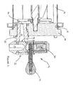
Figure 2 is a side view of part of the machine ofFigure 1 , sectioned along the line II-II inFigure 1 , and showing the dispense valve in greater detail. - In
Figure 1 , a frozenbeverage machine 10 is shown having first and second dispense valves, or taps, 12 for dispensing frozen beverage from first and second freeze barrels 14 (not shown inFigure 1 for clarity). Thetaps 12 are mounted respectively on first andsecond end caps 16. - Referring now to
Figure 2 , thesecond freeze barrel 14 is shown with itsend cap 16 engaged. Aseal 18 is arranged between thefreeze barrel 14 and theend cap 16 to prevent leakage of the beverage from the barrel. - The
end cap 16 supports a transition section in the form of aninlet portion 20 of thedispense tap 12. Theinlet portion 20 in turn carries avalve body portion 22 of thedispense tap 12. - The
inlet portion 20 defines abore 24 of circular cross-section which has aninlet 26 and anoutlet 28. Theoutlet 28 has a diameter greater than the diameter of theinlet 26. It is possible within the scope of the invention that thebore 24 could have a cross-section other than circular. In such an embodiment the cross-section of the outlet and thus cross-sectional area of the outlet is greater than that of the inlet. Theoutlet 28 opens into adispense cavity 30 within thevalve body 22. Thevalve body 22 also has a valve 31, activated by ahandle 32, for controlling the flow of beverage from thefreeze barrel 14 to dispensecavity 30. - In use, upon operation of the
handle 32 to dispense a drink from thetap 12, the valve 31 opens to permit beverage to flow under pressure from thefreeze chamber 14 into thebore 24 and from there into thedispense cavity 30 before exiting thetap 12. Releasing thehandle 32 causes the flow to stop resulting in a volume of frozen beverage remaining in thebore 24. Whilst ice will tend to conglomerate in this section it will slide down the bore to an area of increased cross-sectional area and as a result will not obstruct thebore 24. Consequently, the next time the tap is opened this small volume of ice will be dispensed without causing a blockage in the machine. - The
handle 32 is operated in a rotary manner to align thedispense cavity 30 with theoutlet 28 of thetapered bore 24. Rotary action of thehandle 32 acts against a spring within the valve such that when released the valve returns to its closed position. As can be seen, when the valve is open there are no restrictions within the flowpath from thefreeze barrel 14 through thedispense tap 12 such that there are no features on which any agglomerated ice can become lodged thereby preventing or restricting further flow. Thedispense cavity 30 may be of circular cross-section wherein the diameter of thedispense cavity 30 is at least as great as the diameter of theoutlet 28 of thetapered bore 24. It is possible within the scope of the invention that thedispense cavity 30 may have a cross-section other than circular. It is also possible within the scope of the invention that the cross-section of theoutlet 28 anddispense cavity 30 may be the same or different. It is also possible within the scope of the invention that the cross-section of thedispense cavity 30 is constant or increases in the direction of flow. In such embodiments the minimum dimension of the outlet cavity is at least as great as the maximum dimension of theoutlet 28 such that there is no restriction to flow downstream of theoutlet 28.
Claims (7)
- A dispense valve for a frozen beverage machine having a transition section and a valve body, the transition section arranged to carry frozen beverage from a freeze barrel of the machine to the valve body, the valve body including a valve for controlling flow of frozen beverage from the freeze barrel, wherein the transition section defines a tapered bore having an outlet of greater cross-section than its inlet.
- The dispense valve of claim 1 wherein the bore has a circular cross-section.
- The dispense valve of claim 1 or 2 wherein the bore defines a taper of at least 2 degrees on each side of the bore.
- The dispense valve of any one of claims 1 to 3 wherein the valve has a rotary actuation mechanism.
- The dispense valve of claim 4 wherein the valve body comprises a dispense cavity and rotary motion of the valve body aligns the outlet of the tapered bore with an inlet of the dispense cavity.
- The dispense valve of claim 5 wherein the tapered bore and the dispense cavity are free of any restrictions.
- The dispense valve of claim 5 or claim 6 wherein the cross-section of the flow path within the valve does not decrease downstream of the tapered bore outlet.
Applications Claiming Priority (1)
| Application Number | Priority Date | Filing Date | Title |
|---|---|---|---|
| GBGB0710143.9A GB0710143D0 (en) | 2007-05-26 | 2007-05-26 | Dispense valve |
Publications (1)
| Publication Number | Publication Date |
|---|---|
| EP1997387A2 true EP1997387A2 (en) | 2008-12-03 |
Family
ID=38265424
Family Applications (1)
| Application Number | Title | Priority Date | Filing Date |
|---|---|---|---|
| EP08251802A Withdrawn EP1997387A2 (en) | 2007-05-26 | 2008-05-23 | Dispense valve |
Country Status (3)
| Country | Link |
|---|---|
| US (1) | US8016168B2 (en) |
| EP (1) | EP1997387A2 (en) |
| GB (1) | GB0710143D0 (en) |
Families Citing this family (3)
| Publication number | Priority date | Publication date | Assignee | Title |
|---|---|---|---|---|
| ITBO20130666A1 (en) * | 2013-11-29 | 2015-05-30 | Carpigiani Group Ali Spa | PISTON DISPENSER GROUP OF LIQUID OR SEMILIQUID FOOD PRODUCTS. |
| JP6210088B2 (en) * | 2015-05-20 | 2017-10-11 | トヨタ自動車株式会社 | Tank manufacturing method and tank manufacturing apparatus |
| US10894708B2 (en) | 2018-05-02 | 2021-01-19 | Taylor Commercial Foodservice, Llc | Door and baffle interface assembly for frozen dessert machines |
Family Cites Families (8)
| Publication number | Priority date | Publication date | Assignee | Title |
|---|---|---|---|---|
| US4655374A (en) * | 1985-03-19 | 1987-04-07 | Controle Bvl Ltee | Dispensing apparatus valve |
| CA2097901A1 (en) * | 1993-06-07 | 1994-12-07 | Controles B.V.L. Ltee/B.V.L. Controls, Ltd. | Retaining mechanism for a liquid dispensing apparatus valve |
| US5487493A (en) * | 1994-05-23 | 1996-01-30 | Mcnabb; Rex P. | Frozen beverage dispensing apparatus |
| US5813574A (en) * | 1996-10-18 | 1998-09-29 | Mcnabb; Rex P. | Frozen beverage dispensing apparatus |
| GB2348185B (en) | 1999-03-23 | 2001-03-14 | Imi Cornelius | Dispensing of beverages |
| GB9927061D0 (en) | 1999-11-16 | 2000-01-12 | Imi Cornelius Uk Ltd | Beverage dispense device |
| JP4570283B2 (en) * | 2001-06-08 | 2010-10-27 | ホシザキ電機株式会社 | Foamed beverage pouring cock |
| US6626420B2 (en) * | 2001-12-13 | 2003-09-30 | Vent-Matic Company, Inc. | Dispensing faucet for a pressurized source |
-
2007
- 2007-05-26 GB GBGB0710143.9A patent/GB0710143D0/en not_active Ceased
-
2008
- 2008-05-23 EP EP08251802A patent/EP1997387A2/en not_active Withdrawn
- 2008-05-23 US US12/154,492 patent/US8016168B2/en active Active
Also Published As
| Publication number | Publication date |
|---|---|
| US8016168B2 (en) | 2011-09-13 |
| US20080290308A1 (en) | 2008-11-27 |
| GB0710143D0 (en) | 2007-07-04 |
Similar Documents
| Publication | Publication Date | Title |
|---|---|---|
| US9150401B2 (en) | Beverage dispensing system with a head capable of dispensing plural different beverages | |
| EP1753693B1 (en) | Tap unit for a beverage dispenser | |
| EP1981804B1 (en) | Post-mix beverage dispensing device | |
| EP3596000B1 (en) | Method and apparatus for post-mix drink dispensing | |
| US6588725B1 (en) | Valve | |
| EP2776147B1 (en) | Mixing device and method for producing a carbonated beverage | |
| EP1997387A2 (en) | Dispense valve | |
| US4760940A (en) | Carbonated beverage dispenser having low turbulence valve | |
| GB2415763A (en) | A dispenser tap | |
| US20090014075A1 (en) | Dispenser Tap with Two Stage Valve | |
| EP1163185B1 (en) | Flow regulation valve for a beverage dispenser | |
| US2058631A (en) | Faucet | |
| WO2009036911A1 (en) | Multiple beverage dispensing unit | |
| GB2138541A (en) | A mixed-water cock | |
| EP1528036A2 (en) | Beverage dispense tap | |
| JP2006220398A (en) | Ice dispenser | |
| JP2006220399A (en) | Ice dispenser |
Legal Events
| Date | Code | Title | Description |
|---|---|---|---|
| PUAI | Public reference made under article 153(3) epc to a published international application that has entered the european phase |
Free format text: ORIGINAL CODE: 0009012 |
|
| AK | Designated contracting states |
Kind code of ref document: A2 Designated state(s): AT BE BG CH CY CZ DE DK EE ES FI FR GB GR HR HU IE IS IT LI LT LU LV MC MT NL NO PL PT RO SE SI SK TR |
|
| AX | Request for extension of the european patent |
Extension state: AL BA MK RS |
|
| STAA | Information on the status of an ep patent application or granted ep patent |
Free format text: STATUS: THE APPLICATION IS DEEMED TO BE WITHDRAWN |
|
| 18D | Application deemed to be withdrawn |
Effective date: 20101201 |