EP1997273B1 - Verfahren und system zur verwendung von zählern zur überwachung von eingangspuffern eines systems - Google Patents
Verfahren und system zur verwendung von zählern zur überwachung von eingangspuffern eines systems Download PDFInfo
- Publication number
- EP1997273B1 EP1997273B1 EP07758850A EP07758850A EP1997273B1 EP 1997273 B1 EP1997273 B1 EP 1997273B1 EP 07758850 A EP07758850 A EP 07758850A EP 07758850 A EP07758850 A EP 07758850A EP 1997273 B1 EP1997273 B1 EP 1997273B1
- Authority
- EP
- European Patent Office
- Prior art keywords
- data packets
- queue
- port buffer
- counters
- dropped
- Prior art date
- Legal status (The legal status is an assumption and is not a legal conclusion. Google has not performed a legal analysis and makes no representation as to the accuracy of the status listed.)
- Not-in-force
Links
- 239000000872 buffer Substances 0.000 title claims description 63
- 238000000034 method Methods 0.000 title claims description 32
- 238000003012 network analysis Methods 0.000 claims description 12
- 238000007726 management method Methods 0.000 claims description 10
- 238000012544 monitoring process Methods 0.000 claims description 8
- 230000008569 process Effects 0.000 claims description 5
- 238000010586 diagram Methods 0.000 description 4
- 238000002716 delivery method Methods 0.000 description 3
- 230000008901 benefit Effects 0.000 description 2
- 230000007257 malfunction Effects 0.000 description 2
- 238000012545 processing Methods 0.000 description 2
- 230000002411 adverse Effects 0.000 description 1
- 238000013459 approach Methods 0.000 description 1
- 238000012937 correction Methods 0.000 description 1
- 230000001419 dependent effect Effects 0.000 description 1
- 238000005206 flow analysis Methods 0.000 description 1
- 238000005259 measurement Methods 0.000 description 1
- 238000012986 modification Methods 0.000 description 1
- 230000004048 modification Effects 0.000 description 1
- 230000004044 response Effects 0.000 description 1
Images


Classifications
-
- H—ELECTRICITY
- H04—ELECTRIC COMMUNICATION TECHNIQUE
- H04L—TRANSMISSION OF DIGITAL INFORMATION, e.g. TELEGRAPHIC COMMUNICATION
- H04L41/00—Arrangements for maintenance, administration or management of data switching networks, e.g. of packet switching networks
- H04L41/06—Management of faults, events, alarms or notifications
- H04L41/0677—Localisation of faults
-
- H—ELECTRICITY
- H04—ELECTRIC COMMUNICATION TECHNIQUE
- H04L—TRANSMISSION OF DIGITAL INFORMATION, e.g. TELEGRAPHIC COMMUNICATION
- H04L41/00—Arrangements for maintenance, administration or management of data switching networks, e.g. of packet switching networks
- H04L41/06—Management of faults, events, alarms or notifications
-
- H—ELECTRICITY
- H04—ELECTRIC COMMUNICATION TECHNIQUE
- H04L—TRANSMISSION OF DIGITAL INFORMATION, e.g. TELEGRAPHIC COMMUNICATION
- H04L43/00—Arrangements for monitoring or testing data switching networks
- H04L43/16—Threshold monitoring
-
- H—ELECTRICITY
- H04—ELECTRIC COMMUNICATION TECHNIQUE
- H04L—TRANSMISSION OF DIGITAL INFORMATION, e.g. TELEGRAPHIC COMMUNICATION
- H04L49/00—Packet switching elements
- H04L49/90—Buffering arrangements
-
- H—ELECTRICITY
- H04—ELECTRIC COMMUNICATION TECHNIQUE
- H04L—TRANSMISSION OF DIGITAL INFORMATION, e.g. TELEGRAPHIC COMMUNICATION
- H04L49/00—Packet switching elements
- H04L49/90—Buffering arrangements
- H04L49/9063—Intermediate storage in different physical parts of a node or terminal
-
- H—ELECTRICITY
- H04—ELECTRIC COMMUNICATION TECHNIQUE
- H04L—TRANSMISSION OF DIGITAL INFORMATION, e.g. TELEGRAPHIC COMMUNICATION
- H04L49/00—Packet switching elements
- H04L49/90—Buffering arrangements
- H04L49/9063—Intermediate storage in different physical parts of a node or terminal
- H04L49/9078—Intermediate storage in different physical parts of a node or terminal using an external memory or storage device
Definitions
- the present invention generally relates to monitoring of system port buffers, and in particular to using counters to monitor system port buffers.
- a user may subscribe to multiple data feeds.
- traders in the financial community often subscribe to different market data feeds in order to receive news relevant to trading decisions.
- One perceived advantage of doing so is that the trader may gain a wider perspective by analyzing news from different sources and thus improve the trader's performance.
- a network data delivery device e.g., a switch or a router
- a multicast delivery method is frequently used.
- unicast delivery methods which when used to deliver to multiple recipients sends a duplicate of the data stream from the sender to each recipient; multicast delivery method generates only a single data stream and utilizes a multicast-enabled system, e.g., a router, to duplicate data at the multicast-enabled system and forward duplicated data streams to receivers.
- EP 1351441 discloses an arrangement where a policy manager automatically generates configuration file updates for the routers in the network and, as necessary, sends those updates to the appropriate routers, and causes the routers to install the configuration file updates in real-time.
- US 2006/059163 discloses systems for dynamically mirroring network traffic.
- the network traffic may be mirrored by a mirror service portal from a mirror sender, referred to as a mirror source, to a mirror receiver, referred to as a mirror destination, locally or remotely over various network segments, such as private and public networks and the Internet.
- a mirror sender referred to as a mirror source
- a mirror receiver referred to as a mirror destination
- network segments such as private and public networks and the Internet
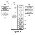
- Figure 1 illustrates a block diagram of an example of a system upon which embodiments in accordance with the present invention may be implemented.
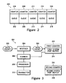
- FIG. 2 illustrates an exemplary system port buffer, in accordance with an embodiment of the present invention.
- Figure 3 illustrates a block diagram of an example of a port buffer monitoring system upon which embodiments in accordance with the present invention may be implemented.
- Figure 4 is a flow chart of a method of using counters to monitor a system port buffer, according to one embodiment of the present invention.
- the method includes forwarding subsequent incoming data packets for the queue received after a predetermined number of data packets for the queue have been dropped into a different system port buffer.
- Figure 5 is a flow chart of a method of using counters to monitor a system port buffer, according to one embodiment of the present invention.
- the method includes forwarding the plurality of data packets into a network analysis module, wherein the forwarding for a queue is terminated if the number of dropped data packets for the queue is greater than a predetermined number.
- a network dam delivery device such as a router or a switch, often receives a significant increase in network traffic when particular events happen. For example, a major news event that affects financial traders can cause network traffic, to increase several fold.
- the network data delivery device's output ports are equipped with system port buffers.
- system port buffers usually the network data delivery device's output ports are equipped with system port buffers.
- Embodiments below describe in detail methods of using counters to monitor the system port buffer and determine the source of the data packets that is causing the system port buffer to overload.
- an individual system port buffer is sub-divided into different queues that receive incoming data packets from different sources. For example, one queue may be designated to receive data packets from a video application device and another queue may be designated to receive data packets from a data application device.
- the queues have associated counters, e.g., a tail drop counter that counts and records the number of dropped data packets for its associated queue of the system port buffer.
- the number of dropped data packets associated with an individual queue is known. Moreover, if it is determined that the number of dropped data packets for a queue is greater than a predetermined number, e.g., zero, then a message is generated and can be sent to a network management station and/or an end user.
- a predetermined number e.g., zero
- the source of the dropped data packets is determined by forwarding subsequent incoming data packets to a different system port buffer that is not overloaded. This is because if a subsequent incoming data packet is not forwarded and simply dropped; all information regarding that data packet may be lost, which makes determination of its source difficult. As a result, by forwarding the data packet and storing it on the non-overloaded system port buffer, the data packet can be accessed and its source may be determined. Furthermore, if the source of the data packets that is causing the system port buffer to ovedoad can be determined, then a network administrator may be able to take corrective actions.
- the source of the dropped data packets is determined by forwarding all incoming data packets before more than a predetermined number of data packets have been dropped into a network analysis module (NAM), and terminating this forwarding upon notice that more than a predetermined number of data packets have been dropped.
- NAM network analysis module
- a network analysis module e.g., zero
- the data packets that caused the overload is usually still in the NAM buffer and not yet overwritten.
- the affected port can be determined and a SYSLOG can be generated.
- the network traffic in the buffer and/or the network traffic enqueued at die time of buffer overflow may be determined.
- a network administrator may be able to reduce down-time and bring affected devices, such as a workstation, back to an operating state more quickly.
- FIG. 1 illustrates a block diagram of an example of a system 100 upon which embodiments in accordance with the present invention may be implemented.
- System 100 shows a video application device 102, a data application device 104, a data delivery device 106, end user 120, end user 122, and ports 108, 110,112,114,116, and 118.
- Video application device 102, data application device 104, end user 120, and end user 122 are all coupled with data delivery device 106.
- each port from ports 108 through 118 includes a system port buffer.
- each system port buffer can include a plurality of queues, and each queue has an associated counter, e.g., a tail drop counter.
- System port buffer 200 includes queue 202 and its associated counter 204, queue 206 and its associated counter 208, queue 210 and its associated counter 212, queue 214 and its associated counter 216, and queue 218 and its associated counter 220.
- An individual queue can be designed to receive data packets from a specific application program device, such as video application device 102 or data application device 104.
- system 100 is shown and described as having certain numbers and types of elements, the present invention is not so limited; that is, system 100 may include elements other than those shown, and may include more than one of the elements that are shown.
- system 100 can include a greater or fewer number of application devices than the two (video application device 102 and data application device 104) shown.
- video application device 102 and data application device sends data packets to data delivery device 106, e.g., a switch. And delivery device 106 duplicates the data packets to multicast.
- data packets from video application 102 and data application device 104 are duplicated hundreds of times and forwarded to ports 108 through 118 to be sent to end users such as end user 120 and 122.
- the data packets overload the system port buffers of port 108 and port 110. Thus, subsequent incoming data packets to port 108 and port 110 may be dropped.
- the counters for the system port buffer are scanned.
- the associated counters count the number of dropped packets for an individual queue of the system port buffer, and if the number of dropped packets is greater than a predetermined number, e.g., zero, a message is generated.
- a message can be, for example, a SYSLOG or a Simple Network Management Protocol trap.
- subsequent incoming data packets for the queue are forwarded into a different system port buffer if the number of dropped data packets for the queue is greater than the predetermined number. Also, the source of the subsequent incoming data packets for the queue may be determined. Additionally, it is understood that forwarding can be implemented in many ways. In one example, forwarding comprises utilizing a Switched Port Analyzer feature.
- the plurality of data packets is forwarded into a network analysis module (NAM), wherein the forwarding for a queue is terminated if the number of dropped data packets for the queue is greater than a predetermined number. Moreover, the network analysis module is accessed and the source of data packets for the queue that immediate precede termination of the forwarding may be determined.
- NAM network analysis module
- Figure 3 illustrates a block diagram of an example of a port buffer monitoring system 300 upon which embodiments in accordance with the present invention may be implemented.
- port monitoring system 300 is shown and described as having certain numbers and types of elements, the present invention is not so limited; that is, system 300 may include elements other than those shown, and may include more than one of the elements that are shown.
- port monitoring system 300 can include a greater number of system port buffers than the two (first system port buffer 314 and second system port buffer 318) shown.
- Port buffer monitoring system 300 includes data packet 302, receiver 304 for receiving data packets, scanner 306 for scanning counters, processor 308, transmitter 310 for forwarding data packets, first system port buffer 314, which includes first counter 312, and second system port buffer 318, which includes second counter 316.
- Receiver 304 and scanner 306 are coupled with first counter 312. Also, receiver 304 is coupled with scanner 306, scanner 306 is coupled with processor 308, and processor 308 is coupled with transmitter 310. Further, transmitter 310 is communicatively coupled with second system port buffer 318. Moreover, in another embodiment, receiver 304, scanner 306, processor 308, and transmitter 310 can all be coupled together via a bus (not shown).
- receiver 304 upon receiving data packet 302, sends data packet 302 towards first system port buffer 314.
- the first system port buffer 314 is unable to receive data packet 302. Consequently, data packet 302 is dropped and first counter 312 registers the dropping of data packet 302.
- Scanner 306 scans first counter 312 and sends the number of dropped data packets, e.g., one data packet, to processor 308.
- Processor 308 determines that the number of dropped data packets is greater than a predetermined numbers, e.g., zero, and generates a message, e.g., a SYSLOG message. Also, any subsequently received data packets may be forwarded towards second system port buffer 318 by transmitter 310. If second system port buffer 318 is able to receive data packets immediately subsequent to the dropped data packet, the source of the dropped data packet may be determined.
- Figure 4 is a flow chart 400 of a method of using counters to monitor a system port buffer, according to one embodiment of the present invention.
- the method includes forwarding subsequent incoming data packets for the queue received after a predetermined number of data packets for the queue have been dropped into a different system port buffer.
- flowchart 400 Although specific steps are disclosed in flowchart 400, such steps are exemplary. That is, embodiments of the present invention are well suited to performing various other or additional steps or variations of the steps recited in flowchart 400. It is appreciated that the steps in flowchart 400 may be performed in an order different than presented.
- a plurality of data packets is received into the system port buffer, wherein the system port buffer comprises a plurality of queues, and wherein an individual counter of a plurality of counters, e.g., a tail drop counter, are associated with each of the plurality of queues.
- an individual counter of a plurality of counters e.g., a tail drop counter
- the counters are scanned, wherein the counters count a number of dropped data packets associated with each of the plurality of queues. In one embodiment, the counters are scanned simultaneously. In another embodiment, the counters are scanned serially.
- a message is generated if the number of dropped data packets is greater than the predetermined number. If the number of dropped data packets for a queue is less than the predetermined number, then the associated counter is subsequently rescanned.
- a message can be, for example, a SYSLOG or a Simple Network Management Protocol trap.
- forwarding comprises utilizing a Switched Port Analyzer feature.
- the source of the subsequent incoming data packets for the queue is determined.
- a processor e.g., a central processing unit (CPU) utilizes information from the data packet and performs a set of instructions to determine its source.
- CPU central processing unit
- the message is sent to one or more network management station(s).
- the network management station may, in one embodiment, be programmed to take responsive actions.
- Figure 5 is a flow chart 500 of a method of using counters to monitor a system port buffer, according to one embodiment of the present invention.
- the method includes forwarding the plurality of data packets into a network analysis module, wherein the forwarding for a queue is terminated if the number of dropped data packets for the queue is greater than a predetermined number.
- flowchart 500 Although specific steps are disclosed in flowchart 500, such steps are exemplary. That is, embodiments of the present invention are well suited to performing various other or additional steps or variations of the steps recited in flowchart 500. It is appreciated that the steps in flowchart 500 may be performed in an order different than presented.
- a plurality of data packets is received into the system port buffer, wherein the system port buffer comprises a plurality of queues, and wherein an individual counter of a plurality of counters are associates with each of the plurality of queues.
- the counters are scanned, wherein the counters count a number of dropped data packets associated with each of the plurality of queues.
- a message is generated if the number of dropped data packets is greater than the predetermined number. If the number of dropped data packets for a queue is less than the predetermined number, then the associated counter is subsequently rescanned.
- a message can be, for example, a SYSLOG or a Simple Network Management Protocol trap.
- the plurality of data packets is forwarded into a network analysis module, wherein the forwarding for a queue is terminated if the number of dropped data packets for the queue is greater than the predetermined number.
- forwarding can be implemented in many ways. In one example, forwarding comprises utilizing a Switched Port Analyzer feature.
- the network analysis module is accessed. Accessing can be implemented in a many ways. In one example, accessing involves transferring information from the network analysis module before reading the information. In another example, information is read directly from the network analysis module.
- the source of data packets for the queue that immediate precede termination of the forwarding is determined.
- a processor e.g., a central processing unit (CPU) utilizes information from the data packet and performs a set of instructions to determine its source.
- CPU central processing unit
- the message is sent to an end user, e.g., a network manager. Also, it is understood that the message can be sent to other users, devices, and/or other application programs.
Landscapes
- Engineering & Computer Science (AREA)
- Computer Networks & Wireless Communication (AREA)
- Signal Processing (AREA)
- Data Exchanges In Wide-Area Networks (AREA)
- Communication Control (AREA)
Claims (18)
- Verfahren zum Verwenden von Zählern zum Überwachen eines System-Port-Zwischenspeichers in einem Datenlieferungsgerät (106), wobei das Verfahren umfasst:Empfangen einer Vielzahl von Datenpaketen in dem System-Port-Zwischenspeicher (200),wobei der System-Port-Zwischenspeicher eine Vielzahl von Warteschlangen (202, 206, 210, 214, 218) aufweist, dadurch gekennzeichnet, dass ein einzelner Zähler einer Vielzahl von Zählern (204, 208, 212, 216, 220) mit jeder der Vielzahl von Warteschlangen assoziiert ist; wobei das Verfahren des Weiteren umfasst:Abtasten der Zähler, wobei die Zähler die Anzahl fallengelassener Datenpakete, die mit jeder der Vielzahl von Warteschlangen assoziiert sind, zählt; undErmitteln, ob die Anzahl fallengelassener Datenpakete für eine einzelne Warteschlange der Vielzahl von Warteschlangen größer ist, als eine vorgegebene Anzahl, wobei eine Nachricht erzeugt wird, wenn die Anzahl fallengelassener Datenpakete größer ist, als die vorgegebene Anzahl.
- Verfahren nach Anspruch 1, das des Weiteren umfasst:Weiterleiten folgender ankommender Datenpakete für die Warteschlange in einen anderen System-Port-Zwischenspeicher, wenn die Anzahl fallengelassener Datenpakete größer ist, als die vorgegebene Anzahl.
- Verfahren nach Anspruch 2, das des Weiteren das Ermitteln der Quelle der folgenden ankommenden Datenpakete für die Warteschlange umfasst.
- Verfahren nach Anspruch 1, das des Weiteren umfasst:Weiterleiten der Vielzahl von Datenpaketen in ein Netzwerk-Analysemodul, wobei das Weiterleiten für eine Warteschlange beendet wird, wenn die Anzahl fallengelassener Datenpakete für diese Warteschlange größer ist, als die vorgegebene Anzahl; undZugreifen auf das Netzwerk-Analysemodul.
- Verfahren nach Anspruch 4, das des Weiteren das Ermitteln der Quelle der Datenpakete für die Warteschlange umfasst, die der Beendigung des Weiterleitens unmittelbar vorangehen.
- Verfahren nach Anspruch 1, wobei die Vielzahl von Datenpaketen durch ein Multicast-Verfahren erzeugt werden.
- Verfahren nach Anspruch 1, das des Weiteren das Senden der Nachricht an eine Netzwerk-Verwaltungsstation umfasst.
- Verfahren nach Anspruch 1, das des Weiteren das Senden der Nachricht an einen Endnutzer umfasst.
- Verfahren nach Anspruch 1, wobei die vorgegebene Anzahl Null ist.
- Verfahren nach Anspruch 1, wobei die erzeugte Nachricht ein SYSLOG ist.
- Verfahren nach Anspruch 1, wobei die erzeugte Nachricht ein Simple Network Management Protocol Trap ist.
- Verfahren nach Anspruch 1, wobei der Zähler ein Taildrop-Zähler ist.
- Port-Zwischenspeicher-Überwachungssystem (300) für ein Datenliefergerät (106), das aufweist:einen System-Port-Zwischenspeicher (200, 314) mit einer Vielzahl von Warteschlangen (202, 206, 210, 214, 218); undeine Empfangseinrichtung (304), die ausgelegt ist zum Empfangen einer Vielzahl von Datenpaketen in dem System-Port-Zwischenspeicher;dadurch gekennzeichnet, dass der System-Port-Zwischenspeicher eine Vielzahl von Zählern (204, 208, 212, 216, 220) aufweist, wobei ein einzelner Zähler der Vielzahl von Zählern mit jeder der Vielzahl von Warteschlangen assoziiert ist; wobei das System des Weiteren aufweist:eine Abtasteinrichtung (306), die ausgelegt ist zum Abtasten der Zähler, wobei die Zähler die Anzahl fallengelassener Datenpakete zählen, die mit jeder der Vielzahl von Warteschlangen assoziiert sind;eine Ermittlungseinrichtung (308), die ausgelegt ist zum Ermitteln, ob die Anzahl fallengelassener Datenpakete für eine einzelne Warteschlange der Vielzahl von Warteschlangen größer ist, als eine vorgegebene Anzahl, wobei eine Nachricht erzeugt wird, wenn die Anzahl fallengelassener Datenpakete größer ist, als die vorgegebene Anzahl.
- System nach Anspruch 13, das des Weiteren aufweist:eine Weiterleitungseinrichtung, die ausgelegt ist zum Weiterleiten folgender ankommender Datenpakete für die Datenschlange, die empfangen werden, nachdem die vorgegebene Anzahl von Datenpaketen für die Warteschlange fallengelassen worden ist, in einen anderen Port-Zwischenspeicher.
- System nach Anspruch 14, das des Weiteren aufweist:eine Ermittlungseinrichtung, die ausgelegt ist zum Ermitteln der Quelle der folgenden ankommenden Datenpakete für die Warteschlange.
- System nach Anspruch 13, das des Weiteren eine Sendeeinrichtung aufweist, die ausgelegt ist zum Senden der Nachricht an eine Netzwerk-Verwaltungsstation.
- System nach Anspruch 13, wobei die vorgebebene Anzahl Null ist.
- System nach Anspruch 13, wobei die erzeugte Nachricht ein Simple Network Management Protocol Trap ist.
Applications Claiming Priority (2)
| Application Number | Priority Date | Filing Date | Title |
|---|---|---|---|
| US11/386,955 US7974196B2 (en) | 2006-03-21 | 2006-03-21 | Method and system of using counters to monitor a system port buffer |
| PCT/US2007/064340 WO2007109637A2 (en) | 2006-03-21 | 2007-03-20 | A method and system of using counters to monitor a system port buffer |
Publications (3)
| Publication Number | Publication Date |
|---|---|
| EP1997273A2 EP1997273A2 (de) | 2008-12-03 |
| EP1997273A4 EP1997273A4 (de) | 2010-04-28 |
| EP1997273B1 true EP1997273B1 (de) | 2012-12-19 |
Family
ID=38523234
Family Applications (1)
| Application Number | Title | Priority Date | Filing Date |
|---|---|---|---|
| EP07758850A Not-in-force EP1997273B1 (de) | 2006-03-21 | 2007-03-20 | Verfahren und system zur verwendung von zählern zur überwachung von eingangspuffern eines systems |
Country Status (3)
| Country | Link |
|---|---|
| US (2) | US7974196B2 (de) |
| EP (1) | EP1997273B1 (de) |
| WO (1) | WO2007109637A2 (de) |
Families Citing this family (13)
| Publication number | Priority date | Publication date | Assignee | Title |
|---|---|---|---|---|
| EP2291954A1 (de) | 2008-06-23 | 2011-03-09 | Koninklijke Philips Electronics N.V. | Verfahren zur kommunikation in einem netzwerk und funkstationen dafür |
| US9258390B2 (en) | 2011-07-29 | 2016-02-09 | Solarflare Communications, Inc. | Reducing network latency |
| US8996644B2 (en) | 2010-12-09 | 2015-03-31 | Solarflare Communications, Inc. | Encapsulated accelerator |
| US9674318B2 (en) | 2010-12-09 | 2017-06-06 | Solarflare Communications, Inc. | TCP processing for devices |
| US9600429B2 (en) | 2010-12-09 | 2017-03-21 | Solarflare Communications, Inc. | Encapsulated accelerator |
| US10873613B2 (en) | 2010-12-09 | 2020-12-22 | Xilinx, Inc. | TCP processing for devices |
| JP2013187616A (ja) * | 2012-03-06 | 2013-09-19 | Fujitsu Ltd | パケット中継装置及びデータパケットの廃棄数の測定方法 |
| US10505747B2 (en) * | 2012-10-16 | 2019-12-10 | Solarflare Communications, Inc. | Feed processing |
| US9495312B2 (en) * | 2013-12-20 | 2016-11-15 | International Business Machines Corporation | Determining command rate based on dropped commands |
| US10834006B2 (en) | 2019-01-24 | 2020-11-10 | Mellanox Technologies, Ltd. | Network traffic disruptions |
| US10999366B2 (en) | 2019-03-10 | 2021-05-04 | Mellanox Technologies Tlv Ltd. | Mirroring dropped packets |
| US12231401B2 (en) | 2022-04-06 | 2025-02-18 | Mellanox Technologies, Ltd | Efficient and flexible flow inspector |
| US12224950B2 (en) | 2022-11-02 | 2025-02-11 | Mellanox Technologies, Ltd | Efficient network device work queue |
Family Cites Families (15)
| Publication number | Priority date | Publication date | Assignee | Title |
|---|---|---|---|---|
| JP3213697B2 (ja) * | 1997-01-14 | 2001-10-02 | 株式会社ディジタル・ビジョン・ラボラトリーズ | 中継ノードシステム及び同システムにおける中継制御方法 |
| US6493318B1 (en) * | 1998-05-04 | 2002-12-10 | Hewlett-Packard Company | Cost propagation switch protocols |
| US20010055274A1 (en) | 2000-02-22 | 2001-12-27 | Doug Hegge | System and method for flow mirroring in a network switch |
| US7120683B2 (en) * | 2000-04-03 | 2006-10-10 | Zarlink Semiconductor V.N. Inc. | Single switch image for a stack of switches |
| WO2002046928A1 (en) * | 2000-12-04 | 2002-06-13 | Rensselaer Polytechnic Institute | Fault detection and prediction for management of computer networks |
| JP4512699B2 (ja) * | 2001-01-11 | 2010-07-28 | 富士通株式会社 | フロー制御装置およびノード装置 |
| US6760867B2 (en) | 2001-03-08 | 2004-07-06 | International Business Machines Corporation | Guaranteed method and apparatus for capture of debug data |
| JP2002300193A (ja) * | 2001-03-30 | 2002-10-11 | Hitachi Ltd | ルータ |
| US7145871B2 (en) | 2002-03-02 | 2006-12-05 | At&T Corp. | Automatic router configuration based on traffic and service level agreements |
| IL164544A0 (en) * | 2003-03-31 | 2005-12-18 | Mitsubishi Electric Corp | Voice transmission apparatus |
| US7474666B2 (en) * | 2003-09-03 | 2009-01-06 | Cisco Technology, Inc. | Switch port analyzers |
| US7499984B2 (en) * | 2004-03-23 | 2009-03-03 | Hewlett-Packard Development Company, L.P. | Status-message mapping |
| US20060005007A1 (en) * | 2004-06-14 | 2006-01-05 | Nokia Corporation | System, method and computer program product for authenticating a data source in multicast communications |
| US8185653B2 (en) * | 2004-08-09 | 2012-05-22 | Johnny Yau | Method and apparatus for ad hoc mesh routing |
| US8819213B2 (en) | 2004-08-20 | 2014-08-26 | Extreme Networks, Inc. | System, method and apparatus for traffic mirror setup, service and security in communication networks |
-
2006
- 2006-03-21 US US11/386,955 patent/US7974196B2/en active Active
-
2007
- 2007-03-20 EP EP07758850A patent/EP1997273B1/de not_active Not-in-force
- 2007-03-20 WO PCT/US2007/064340 patent/WO2007109637A2/en not_active Ceased
-
2011
- 2011-05-02 US US13/099,286 patent/US8531960B2/en not_active Expired - Fee Related
Also Published As
| Publication number | Publication date |
|---|---|
| EP1997273A2 (de) | 2008-12-03 |
| US20110205893A1 (en) | 2011-08-25 |
| US7974196B2 (en) | 2011-07-05 |
| WO2007109637A2 (en) | 2007-09-27 |
| US8531960B2 (en) | 2013-09-10 |
| US20070223385A1 (en) | 2007-09-27 |
| WO2007109637A3 (en) | 2008-07-10 |
| EP1997273A4 (de) | 2010-04-28 |
Similar Documents
| Publication | Publication Date | Title |
|---|---|---|
| EP1997273B1 (de) | Verfahren und system zur verwendung von zählern zur überwachung von eingangspuffern eines systems | |
| US6392996B1 (en) | Method and apparatus for frame peeking | |
| US8040884B2 (en) | Constraining multicast traffic between a layer 2 network device and a router | |
| US20170244617A1 (en) | Method and System to Monitor a Network | |
| US20040010473A1 (en) | Rule-based packet selection, storage, and access method and system | |
| US11606448B2 (en) | Efficient capture and streaming of data packets | |
| US20080002703A1 (en) | System and method for virtual network interface cards based on internet protocol addresses | |
| US20080198754A1 (en) | Method and system for testing a communication network | |
| CN111314179B (zh) | 网络质量检测方法、装置、设备和存储介质 | |
| EP2668734B1 (de) | Bereitstellung von kapazitätsoptimierten streaming-daten mit vorwärtsfehlerkorrektur | |
| US9269080B2 (en) | Hierarchical publish/subscribe system | |
| CN101035037A (zh) | 检测网络通信质量的方法、系统及相关装置 | |
| US9569753B2 (en) | Hierarchical publish/subscribe system performed by multiple central relays | |
| CN116886609A (zh) | 拥塞控制方法及装置、通信网络、计算机存储介质 | |
| CN112260899A (zh) | 基于mmu的网络监测方法和装置 | |
| CN101355585A (zh) | 一种分布式架构数据通信设备的消息保护系统及方法 | |
| CN112104564A (zh) | 一种负载分担方法及设备 | |
| JP2018067829A (ja) | 即時トラフィック収集・分析システム及び方法 | |
| CN100466603C (zh) | 对网络中传输的业务流进行整形的方法及装置 | |
| CN114765585A (zh) | 一种服务质量检测方法、报文处理方法及装置 | |
| US7483388B2 (en) | Method and system for sending a multimedia stream in an IP multicast network | |
| US20080123649A1 (en) | Systems and methods for broadcast storm control | |
| CN110336759B (zh) | 基于rdma的协议报文转发方法及装置 | |
| US12237938B2 (en) | Prioritizing multicast streams in internet group management protocol (IGMP) networks | |
| TWI581590B (zh) | Real - time traffic collection and analysis system and method |
Legal Events
| Date | Code | Title | Description |
|---|---|---|---|
| PUAI | Public reference made under article 153(3) epc to a published international application that has entered the european phase |
Free format text: ORIGINAL CODE: 0009012 |
|
| 17P | Request for examination filed |
Effective date: 20080929 |
|
| AK | Designated contracting states |
Kind code of ref document: A2 Designated state(s): AT BE BG CH CY CZ DE DK EE ES FI FR GB GR HU IE IS IT LI LT LU LV MC MT NL PL PT RO SE SI SK TR |
|
| AX | Request for extension of the european patent |
Extension state: AL BA HR MK RS |
|
| A4 | Supplementary search report drawn up and despatched |
Effective date: 20100330 |
|
| 17Q | First examination report despatched |
Effective date: 20100707 |
|
| REG | Reference to a national code |
Ref country code: DE Ref legal event code: R079 Ref document number: 602007027492 Country of ref document: DE Free format text: PREVIOUS MAIN CLASS: H04L0012180000 Ipc: H04L0012240000 |
|
| GRAP | Despatch of communication of intention to grant a patent |
Free format text: ORIGINAL CODE: EPIDOSNIGR1 |
|
| RIC1 | Information provided on ipc code assigned before grant |
Ipc: H04L 12/56 20060101ALI20120612BHEP Ipc: H04L 12/26 20060101ALI20120612BHEP Ipc: H04L 12/24 20060101AFI20120612BHEP |
|
| DAX | Request for extension of the european patent (deleted) | ||
| GRAS | Grant fee paid |
Free format text: ORIGINAL CODE: EPIDOSNIGR3 |
|
| GRAA | (expected) grant |
Free format text: ORIGINAL CODE: 0009210 |
|
| AK | Designated contracting states |
Kind code of ref document: B1 Designated state(s): AT BE BG CH CY CZ DE DK EE ES FI FR GB GR HU IE IS IT LI LT LU LV MC MT NL PL PT RO SE SI SK TR |
|
| REG | Reference to a national code |
Ref country code: GB Ref legal event code: FG4D |
|
| REG | Reference to a national code |
Ref country code: CH Ref legal event code: EP |
|
| REG | Reference to a national code |
Ref country code: AT Ref legal event code: REF Ref document number: 589865 Country of ref document: AT Kind code of ref document: T Effective date: 20130115 |
|
| REG | Reference to a national code |
Ref country code: DE Ref legal event code: R096 Ref document number: 602007027492 Country of ref document: DE Effective date: 20130307 |
|
| PG25 | Lapsed in a contracting state [announced via postgrant information from national office to epo] |
Ref country code: FI Free format text: LAPSE BECAUSE OF FAILURE TO SUBMIT A TRANSLATION OF THE DESCRIPTION OR TO PAY THE FEE WITHIN THE PRESCRIBED TIME-LIMIT Effective date: 20121219 Ref country code: SE Free format text: LAPSE BECAUSE OF FAILURE TO SUBMIT A TRANSLATION OF THE DESCRIPTION OR TO PAY THE FEE WITHIN THE PRESCRIBED TIME-LIMIT Effective date: 20121219 Ref country code: ES Free format text: LAPSE BECAUSE OF FAILURE TO SUBMIT A TRANSLATION OF THE DESCRIPTION OR TO PAY THE FEE WITHIN THE PRESCRIBED TIME-LIMIT Effective date: 20130330 Ref country code: LT Free format text: LAPSE BECAUSE OF FAILURE TO SUBMIT A TRANSLATION OF THE DESCRIPTION OR TO PAY THE FEE WITHIN THE PRESCRIBED TIME-LIMIT Effective date: 20121219 |
|
| REG | Reference to a national code |
Ref country code: NL Ref legal event code: VDEP Effective date: 20121219 Ref country code: AT Ref legal event code: MK05 Ref document number: 589865 Country of ref document: AT Kind code of ref document: T Effective date: 20121219 |
|
| REG | Reference to a national code |
Ref country code: LT Ref legal event code: MG4D |
|
| PG25 | Lapsed in a contracting state [announced via postgrant information from national office to epo] |
Ref country code: GR Free format text: LAPSE BECAUSE OF FAILURE TO SUBMIT A TRANSLATION OF THE DESCRIPTION OR TO PAY THE FEE WITHIN THE PRESCRIBED TIME-LIMIT Effective date: 20130320 Ref country code: SI Free format text: LAPSE BECAUSE OF FAILURE TO SUBMIT A TRANSLATION OF THE DESCRIPTION OR TO PAY THE FEE WITHIN THE PRESCRIBED TIME-LIMIT Effective date: 20121219 Ref country code: LV Free format text: LAPSE BECAUSE OF FAILURE TO SUBMIT A TRANSLATION OF THE DESCRIPTION OR TO PAY THE FEE WITHIN THE PRESCRIBED TIME-LIMIT Effective date: 20121219 |
|
| PG25 | Lapsed in a contracting state [announced via postgrant information from national office to epo] |
Ref country code: CZ Free format text: LAPSE BECAUSE OF FAILURE TO SUBMIT A TRANSLATION OF THE DESCRIPTION OR TO PAY THE FEE WITHIN THE PRESCRIBED TIME-LIMIT Effective date: 20121219 Ref country code: AT Free format text: LAPSE BECAUSE OF FAILURE TO SUBMIT A TRANSLATION OF THE DESCRIPTION OR TO PAY THE FEE WITHIN THE PRESCRIBED TIME-LIMIT Effective date: 20121219 Ref country code: CY Free format text: LAPSE BECAUSE OF FAILURE TO SUBMIT A TRANSLATION OF THE DESCRIPTION OR TO PAY THE FEE WITHIN THE PRESCRIBED TIME-LIMIT Effective date: 20121219 Ref country code: SK Free format text: LAPSE BECAUSE OF FAILURE TO SUBMIT A TRANSLATION OF THE DESCRIPTION OR TO PAY THE FEE WITHIN THE PRESCRIBED TIME-LIMIT Effective date: 20121219 Ref country code: BE Free format text: LAPSE BECAUSE OF FAILURE TO SUBMIT A TRANSLATION OF THE DESCRIPTION OR TO PAY THE FEE WITHIN THE PRESCRIBED TIME-LIMIT Effective date: 20121219 Ref country code: EE Free format text: LAPSE BECAUSE OF FAILURE TO SUBMIT A TRANSLATION OF THE DESCRIPTION OR TO PAY THE FEE WITHIN THE PRESCRIBED TIME-LIMIT Effective date: 20121219 Ref country code: BG Free format text: LAPSE BECAUSE OF FAILURE TO SUBMIT A TRANSLATION OF THE DESCRIPTION OR TO PAY THE FEE WITHIN THE PRESCRIBED TIME-LIMIT Effective date: 20130319 Ref country code: IS Free format text: LAPSE BECAUSE OF FAILURE TO SUBMIT A TRANSLATION OF THE DESCRIPTION OR TO PAY THE FEE WITHIN THE PRESCRIBED TIME-LIMIT Effective date: 20130419 |
|
| PG25 | Lapsed in a contracting state [announced via postgrant information from national office to epo] |
Ref country code: NL Free format text: LAPSE BECAUSE OF FAILURE TO SUBMIT A TRANSLATION OF THE DESCRIPTION OR TO PAY THE FEE WITHIN THE PRESCRIBED TIME-LIMIT Effective date: 20121219 Ref country code: PL Free format text: LAPSE BECAUSE OF FAILURE TO SUBMIT A TRANSLATION OF THE DESCRIPTION OR TO PAY THE FEE WITHIN THE PRESCRIBED TIME-LIMIT Effective date: 20121219 Ref country code: RO Free format text: LAPSE BECAUSE OF FAILURE TO SUBMIT A TRANSLATION OF THE DESCRIPTION OR TO PAY THE FEE WITHIN THE PRESCRIBED TIME-LIMIT Effective date: 20121219 Ref country code: PT Free format text: LAPSE BECAUSE OF FAILURE TO SUBMIT A TRANSLATION OF THE DESCRIPTION OR TO PAY THE FEE WITHIN THE PRESCRIBED TIME-LIMIT Effective date: 20130419 |
|
| PLBE | No opposition filed within time limit |
Free format text: ORIGINAL CODE: 0009261 |
|
| STAA | Information on the status of an ep patent application or granted ep patent |
Free format text: STATUS: NO OPPOSITION FILED WITHIN TIME LIMIT |
|
| PG25 | Lapsed in a contracting state [announced via postgrant information from national office to epo] |
Ref country code: MC Free format text: LAPSE BECAUSE OF NON-PAYMENT OF DUE FEES Effective date: 20130331 Ref country code: DK Free format text: LAPSE BECAUSE OF FAILURE TO SUBMIT A TRANSLATION OF THE DESCRIPTION OR TO PAY THE FEE WITHIN THE PRESCRIBED TIME-LIMIT Effective date: 20121219 |
|
| REG | Reference to a national code |
Ref country code: CH Ref legal event code: PL |
|
| 26N | No opposition filed |
Effective date: 20130920 |
|
| PG25 | Lapsed in a contracting state [announced via postgrant information from national office to epo] |
Ref country code: IT Free format text: LAPSE BECAUSE OF FAILURE TO SUBMIT A TRANSLATION OF THE DESCRIPTION OR TO PAY THE FEE WITHIN THE PRESCRIBED TIME-LIMIT Effective date: 20121219 |
|
| REG | Reference to a national code |
Ref country code: IE Ref legal event code: MM4A |
|
| REG | Reference to a national code |
Ref country code: DE Ref legal event code: R097 Ref document number: 602007027492 Country of ref document: DE Effective date: 20130920 |
|
| PG25 | Lapsed in a contracting state [announced via postgrant information from national office to epo] |
Ref country code: CH Free format text: LAPSE BECAUSE OF NON-PAYMENT OF DUE FEES Effective date: 20130331 Ref country code: LI Free format text: LAPSE BECAUSE OF NON-PAYMENT OF DUE FEES Effective date: 20130331 Ref country code: IE Free format text: LAPSE BECAUSE OF NON-PAYMENT OF DUE FEES Effective date: 20130320 |
|
| PG25 | Lapsed in a contracting state [announced via postgrant information from national office to epo] |
Ref country code: MT Free format text: LAPSE BECAUSE OF FAILURE TO SUBMIT A TRANSLATION OF THE DESCRIPTION OR TO PAY THE FEE WITHIN THE PRESCRIBED TIME-LIMIT Effective date: 20121219 |
|
| REG | Reference to a national code |
Ref country code: FR Ref legal event code: PLFP Year of fee payment: 9 |
|
| PG25 | Lapsed in a contracting state [announced via postgrant information from national office to epo] |
Ref country code: TR Free format text: LAPSE BECAUSE OF FAILURE TO SUBMIT A TRANSLATION OF THE DESCRIPTION OR TO PAY THE FEE WITHIN THE PRESCRIBED TIME-LIMIT Effective date: 20121219 |
|
| PG25 | Lapsed in a contracting state [announced via postgrant information from national office to epo] |
Ref country code: LU Free format text: LAPSE BECAUSE OF NON-PAYMENT OF DUE FEES Effective date: 20130320 Ref country code: HU Free format text: LAPSE BECAUSE OF FAILURE TO SUBMIT A TRANSLATION OF THE DESCRIPTION OR TO PAY THE FEE WITHIN THE PRESCRIBED TIME-LIMIT; INVALID AB INITIO Effective date: 20070320 |
|
| REG | Reference to a national code |
Ref country code: FR Ref legal event code: PLFP Year of fee payment: 10 |
|
| REG | Reference to a national code |
Ref country code: FR Ref legal event code: PLFP Year of fee payment: 11 |
|
| REG | Reference to a national code |
Ref country code: FR Ref legal event code: PLFP Year of fee payment: 12 |
|
| PGFP | Annual fee paid to national office [announced via postgrant information from national office to epo] |
Ref country code: GB Payment date: 20200327 Year of fee payment: 14 Ref country code: DE Payment date: 20200327 Year of fee payment: 14 |
|
| PGFP | Annual fee paid to national office [announced via postgrant information from national office to epo] |
Ref country code: FR Payment date: 20200325 Year of fee payment: 14 |
|
| REG | Reference to a national code |
Ref country code: DE Ref legal event code: R119 Ref document number: 602007027492 Country of ref document: DE |
|
| GBPC | Gb: european patent ceased through non-payment of renewal fee |
Effective date: 20210320 |
|
| PG25 | Lapsed in a contracting state [announced via postgrant information from national office to epo] |
Ref country code: DE Free format text: LAPSE BECAUSE OF NON-PAYMENT OF DUE FEES Effective date: 20211001 Ref country code: FR Free format text: LAPSE BECAUSE OF NON-PAYMENT OF DUE FEES Effective date: 20210331 Ref country code: GB Free format text: LAPSE BECAUSE OF NON-PAYMENT OF DUE FEES Effective date: 20210320 |
|
| P01 | Opt-out of the competence of the unified patent court (upc) registered |
Effective date: 20230525 |