EP1996989B1 - Temperature-controlled enclosures and temperature control system using the same - Google Patents
Temperature-controlled enclosures and temperature control system using the same Download PDFInfo
- Publication number
- EP1996989B1 EP1996989B1 EP07753004.6A EP07753004A EP1996989B1 EP 1996989 B1 EP1996989 B1 EP 1996989B1 EP 07753004 A EP07753004 A EP 07753004A EP 1996989 B1 EP1996989 B1 EP 1996989B1
- Authority
- EP
- European Patent Office
- Prior art keywords
- chamber
- temperature
- module
- fluid
- manifold
- Prior art date
- Legal status (The legal status is an assumption and is not a legal conclusion. Google has not performed a legal analysis and makes no representation as to the accuracy of the status listed.)
- Not-in-force
Links
Images








Classifications
-
- B—PERFORMING OPERATIONS; TRANSPORTING
- B01—PHYSICAL OR CHEMICAL PROCESSES OR APPARATUS IN GENERAL
- B01L—CHEMICAL OR PHYSICAL LABORATORY APPARATUS FOR GENERAL USE
- B01L1/00—Enclosures; Chambers
-
- F—MECHANICAL ENGINEERING; LIGHTING; HEATING; WEAPONS; BLASTING
- F25—REFRIGERATION OR COOLING; COMBINED HEATING AND REFRIGERATION SYSTEMS; HEAT PUMP SYSTEMS; MANUFACTURE OR STORAGE OF ICE; LIQUEFACTION SOLIDIFICATION OF GASES
- F25D—REFRIGERATORS; COLD ROOMS; ICE-BOXES; COOLING OR FREEZING APPARATUS NOT OTHERWISE PROVIDED FOR
- F25D23/00—General constructional features
- F25D23/06—Walls
- F25D23/061—Walls with conduit means
-
- G—PHYSICS
- G01—MEASURING; TESTING
- G01M—TESTING STATIC OR DYNAMIC BALANCE OF MACHINES OR STRUCTURES; TESTING OF STRUCTURES OR APPARATUS, NOT OTHERWISE PROVIDED FOR
- G01M99/00—Subject matter not provided for in other groups of this subclass
- G01M99/002—Thermal testing
-
- B—PERFORMING OPERATIONS; TRANSPORTING
- B01—PHYSICAL OR CHEMICAL PROCESSES OR APPARATUS IN GENERAL
- B01L—CHEMICAL OR PHYSICAL LABORATORY APPARATUS FOR GENERAL USE
- B01L2200/00—Solutions for specific problems relating to chemical or physical laboratory apparatus
- B01L2200/14—Process control and prevention of errors
- B01L2200/143—Quality control, feedback systems
- B01L2200/147—Employing temperature sensors
-
- B—PERFORMING OPERATIONS; TRANSPORTING
- B01—PHYSICAL OR CHEMICAL PROCESSES OR APPARATUS IN GENERAL
- B01L—CHEMICAL OR PHYSICAL LABORATORY APPARATUS FOR GENERAL USE
- B01L2300/00—Additional constructional details
- B01L2300/18—Means for temperature control
- B01L2300/1838—Means for temperature control using fluid heat transfer medium
-
- B—PERFORMING OPERATIONS; TRANSPORTING
- B01—PHYSICAL OR CHEMICAL PROCESSES OR APPARATUS IN GENERAL
- B01L—CHEMICAL OR PHYSICAL LABORATORY APPARATUS FOR GENERAL USE
- B01L7/00—Heating or cooling apparatus; Heat insulating devices
Definitions
- This invention relates generally to a temperature-controlled enclosure for connecting to a source of temperature-controlled fluid, such as air, and a system including the enclosure and the source.
- This invention relates in particular to a temperature-controlled chamber that includes thermal insulation, a means of directing air to a device being tested, an exhausting system and a self-closing cable feed-through module.
- standard temperature chambers There are many manufacturers of standard temperature chambers. In general, in such chambers, air is circulated in a closed loop with a fan or blower directing the air over a heating and/or cooling coil to condition the temperature of the air before it enters a test area. The air then exits the test area and is again directed over the heating and/or cooling coil to condition the temperature of the air before it reenters the test area. These steps are repeated.
- the standard temperature chambers simply circulate the air with no method for directing the air to the device being tested.
- the standard temperature chambers use a metal (or other material) liner inside the chamber. The metal liner acts as a thermal load and significantly increases the time to transition between set temperatures.
- US 5 271 230 discloses an apparatus and method for lowering the temperature within a chamber from a higher actual value to a set desired lower value, the latter being stabilized by intermittently flowing liquid gas, selectively, through the chamber and a venting orifice, under the control of a microcomputer responding to a temperature sensor within the chamber.
- US 6 098 473 discloses an air chamber which has Milli-Kelvin temperature control. This is achieved by the use of coarse and fine temperature control systems, and through the use of a structure for handling air flow within the chamber.
- the coarse control system provides enough heating or cooling power to hold the chamber temperature at a value near, but below, the desired operating temperature, thus leaving a small differential to be made up by the fine control loop.
- a chamber in which a device can be located, the chamber being connectable to a temperature-controlled source for providing a temperature-controlled fluid to the chamber to control temperature of the chamber; and a self-closing cable feed-through module connected to an outer surface of the chamber, the module comprising a first portion and a second portion, wherein cables are fed through the first and second portions into the chamber in a first position of the module and the first and second portions form a leak tight seal around the cables in a second position of the module.
- the temperature chamber further comprises an exhaust system for exhausting the fluid from the chamber.
- the exhaust system comprises a plurality of exhaust ports connected internal to the chamber and a single outlet port for allowing the fluid to exit the chamber.
- the exhaust system comprises a plurality of exhaust ports connected internal to the chamber and multiple outlet ports for allowing the fluid to exit the chamber.
- the exhaust system comprises an exhaust port centrally located in the bottom of the chamber and an outlet port for allowing the fluid to exit the rear of the chamber.
- a location of an exhaust is selectable by a user.
- the temperature chamber further comprises thermal insulation material formed on side surfaces of the chamber.
- the chamber has a hood configuration.
- a thin layer of silicone is bonded to the surface of the thermal insulation material.
- the thermal insulation material is positioned between an outer shell of the chamber and an inner liner of the chamber.
- the inner liner of the chamber is thermally decoupled from the outer shell.
- the chamber has a clamshell configuration in which a top portion of the chamber is connected to a bottom portion of the chamber such that the top portion is opened in order to load the device into the chamber.
- the chamber has a front-loader configuration in which a front portion of the chamber is connected to a rear portion of the chamber such that the front portion is opened in order to load the device into the chamber.
- the fluid is air.
- the temperature chamber further comprises a universal manifold adaptor for directing the temperature-controlled fluid directly to the device.
- interchangeable manifolds are attachable to the universal manifold to direct the fluid to the device.
- a manifold comprises a single horizontal tube with multiple small holes for discharge of the fluid.
- a manifold comprises a plurality of horizontal tubes with multiple small holes for discharge of the fluid.
- a manifold has a shower-head configuration to provide uniform distribution of the fluid.
- a manifold comprises a baffle system.
- the self-closing cable feed-through module is removable from the chamber.
- the self-closing cable feed-through module is installed into a wall of the chamber, and clamps secure the self-closing cable feed-through module to the chamber.
- the temperature chamber further comprises a dry air source for providing dry air to the self-closing cable feed-through module.
- the self-closing cable feed-through module comprises a joint for rotating the second portion relative to the first portion.
- the self-closing cable feed-through module further comprises insulation.
- the chamber is connected to a temperature-controlled source for providing a temperature-controlled fluid to the chamber to control temperature of the chamber;
- a source of temperature-controlled fluid such as air, for example, ThermoStreamTM model TP04300 or TP04310, manufactured and sold by Temptronic Corporation of Sharon, Massachusetts, is used as an open-loop temperature source for controlling the temperature within a temperature chamber.
- the source is either attached directly to the inlet of the temperature chamber or there is a flexible air transfer line, i.e., a flexible extender, that connects a source head to the temperature chamber inlet.
- the temperature-controlled air exhausts out of the temperature chamber.
- the device being tested in the temperature chamber could be a printed circuit board, mechanical or electronic module or any other device requiring thermal test.
- the source can be used as a temperature source for temperature testing various devices without attaching to a temperature chamber.
- the present invention includes a family of interchangeable temperature chambers for . use with the source, i.e., the open-loop temperature source.
- the features of the chambers include a highly efficient thermal insulation design that provides overall improvement in thermal performance by minimizing heat loss and reducing thermal loads, a highly efficient and field changeable method of air distribution for improved thermal response for specific testing applications, unique air exhaust systems for optimizing temperature uniformity, and a self-closing cable feed-through module.
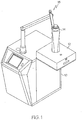
- FIG. 1 is a schematic perspective view of a hood chamber 12 according to an embodiment of the invention connected to a source 10 of temperature-controlled fluid such as air.
- the source 10 can be, for example, a ThermoStreamTM model TP04300 or TP04310, manufactured and sold by Temptronic Corporation of Sharon, Massachusetts, or other similar device.
- the source 10 is used as the temperature-controlled air source for controlling the temperature within the hood chamber 12.
- a head 14 of the source 10 attaches directly to the top side of the hood chamber 12 with three knurled screws. No tools are required to attach the head 14 to the hood chamber 12.
- the head 14 is attached to the source 10 by a pivoting arm 15.
- FIGs. 2A-2E are schematic views of the hood chamber 12 of FIG. 1 with a universal manifold adapter 20 in accordance with an embodiment of the invention.
- the hood chamber 12 is provided with the universal manifold adapter 20 designed to improve temperature response which reduces time for completion of a test and, therefore, reduces the test cost.
- the universal manifold adapter 20 allows interchangeable manifolds to be used to optimize temperature testing.
- FIGs. 2A-2E illustrate the interchangeable manifolds.
- To optimize thermal performance it is desirable that the temperature-controlled air being supplied by the source 10 be directed to the device being tested. Conventional thermal enclosures (chambers) simply circulate the air with no method for directing the air to the device being tested.
- a manifold can be added to direct the temperature-controlled air directly to the device being tested.
- FIG. 2A is a schematic view of the hood 12 with the universal manifold adaptor 20 with no manifolds attached thereto.
- the universal manifold adapter 20 has several attachment points (holes) that allow attachment of interchangeable manifolds.
- the manifold can be a single horizontal tube 22 with multiple small holes for air discharge.
- the manifold can be two or more horizontal tubes 22.
- FIG. 2B is a schematic view of the hood chamber 12 with two horizontal tubes 22 with multiple small holes for air discharge attached to the universal manifold adapter 20.
- the manifold can be a piece of flexible tube to better direct air on the device being tested.
- the manifold can be a shower head type to provide uniform distribution of temperature-controlled air, or any other manifold for distribution of temperature-controlled air.
- FIG. 2C is a schematic view of the hood chamber 12 with a shower-head type manifold 24 attached to the universal manifold adaptor 20.
- FIG. 2D is a schematic view of the hood chamber 12 with a shower-head type manifold 24 attached to the universal manifold adaptor 20 and exhaust ports 26 at side portions of the hood chamber 12.
- FIG. 2E is a schematic view of the hood chamber 12 with a shower-head manifold 24 and four horizontal tubes 22 with multiple small holes for air discharge attached to the universal manifold adaptor 20.
- FIG. 3 is a schematic perspective view of the hood chamber 12 of FIG. 1 in accordance with an embodiment of the invention.
- the thermal insulation design used for the hood chamber 12 as shown in FIG. 3 allows temperature changes to occur much faster than with existing approaches.
- the hood chamber 12 includes a layer of thermal insulation 16 with a thin layer of silicone 18 bonded to the surface of the insulation 16.
- the bonded layer 18 provides needed protection against damage to the insulation 16.
- the bonded layer 18 eliminates the need for a metal (or other material) liner inside the hood chamber 12, which would act as a thermal load and significantly increase the time to transition between set temperatures.
- the hood chamber 12 includes a handle 23.
- FIG. 4 is a schematic perspective view of the hood chamber 12 of FIG. 1 in accordance with an embodiment of the invention.
- the hood chamber 12 is disconnected from the air source 10.
- An air-in connection 25 is used to connect to the source 10.
- the hood chamber 12 also incorporates a unique air exhausting system to optimize temperature uniformity within the test area. All hood chamber configurations provide multiple exhaust areas within the test areas to ensure uniform air distribution throughout the test area. The exhaust areas are typically located in side portions of the hood chamber 12 but can be in other locations if necessary to optimize uniformity. As shown in FIG. 2D and FIG. 3 , exhaust ports 26 are located at side portions of the hood chamber. 12. As shown in FIG. 2D and FIG. 3 , all of the exhaust ports 26 are connected internal to the hood chamber 12 with only one exit exhaust 28 exiting the hood chamber 12 being used in a selected configuration. Internal route 27 is the route of the exhaust in the hood chamber 12. The exhaust location is user selectable (first and second exit ports 28, which are 90 degrees apart) for test operator convenience.
- the hood chamber 12 includes a handle 23.
- FIGs. 5A and 5B are schematic perspective views of a clamshell chamber 30 connected to the source 10, in accordance with an embodiment of the invention.
- the clamshell chamber 30 is top-loaded such that the device being tested is loaded into the chamber from the top.
- a source 10 is used as the temperature-controlled air source for controlling the temperature within the clamshell chamber 30.
- the head 14 of the source 10 attaches to the side of the clamshell chamber 30 via a flex extender 32 which transfers the temperature-controlled air from the source 10 to the clamshell chamber 30.
- the head 14 is connected to a pivoting arm 15.
- FIG. 5A is schematic perspective views of a clamshell chamber 30 connected to the source 10, in accordance with an embodiment of the invention.
- the clamshell chamber 30 is top-loaded such that the device being tested is loaded into the chamber from the top.
- a source 10 is used as the temperature-controlled air source for controlling the temperature within the clamshell chamber 30.
- the head 14 of the source 10 attaches to the side
- the output of the source 10 attaches to the side of the clamshell chamber 30 via the flex extender 32 which transfers the temperature-controlled air from the source 10 to the clamshell chamber 30.
- Attachment of the flex extender 32 to the clamshell chamber 30 is made with three knurled screws. No tools are required to attach the flex extender 32 to the clamshell chamber 30. The attachment can be made to either side of the clamshell chamber for convenience.
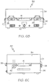
- FIGs. 6A-6E are schematic views of a clamshell chamber 30 of FIGs. 5A and 5B in accordance with an embodiment of the present invention.
- FIG. 6A is a schematic top view of the clamshell chamber 30.
- FIG. 6B is a schematic rear view of the clamshell chamber 30.
- FIG. 6C is a schematic front view of clamshell chamber 30.
- FIG. 6D is a schematic view of the clamshell chamber 30 in an open position.
- FIG. 6E is a schematic cross-sectional view of the clamshell chamber 30 along section E-E of FIG. 6A in accordance with an embodiment of the present invention.
- the clamshell chamber 30 includes a top portion 34 connected to a bottom portion 36 by a hinges 35. When the clamshell chamber 30 is closed, the top and bottom portions 34 and 36 are latched together by latches 33.
- the clamshell 30 includes four cable feed-through openings 41 for connecting cables to the interior of the clamshell chamber 30 on each side of the clamshell chamber 30.
- the thermal insulation design used for the clamshell chamber 30 and as shown in FIG. 6E allows temperature changes to occur much faster than with existing approaches.
- the clamshell chamber 30 uses thermal insulation 43, i.e., foam, between the outer shell 37 of the clamshell chamber 30 and the inner liner 39 of the clamshell chamber 30.
- the inner liner 39 protects the insulation 43 from damage that might result from frequent use.
- the inner liner 39 is thermally decoupled from the outer shell 37 to minimize thermal losses and optimize thermal performance, i.e., temperature response and temperature uniformity.
- the inner liner 39 is made of very thin stainless steel to minimize thermal load, but could be other suitable materials.
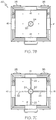
- FIGs. 7A-7C are schematic views of the clamshell chamber 30 of FIGs. 5A and 5B with a universal manifold adapter 20 in accordance with an embodiment of the invention.
- the clamshell chamber 30 is provided with the universal manifold adapter 20 to improve temperature response which reduces time for completion of a test and, therefore, reduces test cost.
- the universal manifold adapter 20 allows interchangeable manifolds to be used to optimize temperature testing. To optimize thermal performance it is desirable that the temperature-controlled air being supplied by the source 10 be directed to the device being tested. Conventional thermal enclosures (chambers) simply circulate the air with no method for directing the air to the device being tested. With the universal manifold adapter 20 in the clamshell chamber 30, a manifold can be added to direct the temperature-controlled air directly to the device being tested.
- the universal manifold adapter 20 allows the air distribution manifold to be changed to a different configuration if necessary to accommodate changes in test requirements within the same clamshell chamber.
- the universal manifold adapter 20 has several attachment points (holes) that allow attachment of interchangeable manifolds.
- the manifold can be a single horizontal tube 22 with multiple small holes for air discharge.
- the manifold can be two or more horizontal tubes 22.
- FIG. 7A is a schematic diagram of the clamshell chamber 30 with two horizontal tubes 22 with multiple small holes for air discharge attached to the universal manifold adapter 20.
- the manifold can be a piece of flexible tube to better direct air on the device being tested.
- the manifold can be a shower-head type to provide uniform distribution of temperature-controlled air, or any other manifold for distribution of temperature-controlled air.
- FIG. 7B is a schematic diagram of the clamshell chamber 30 with a shower-head type manifold 24 attached to the universal manifold adaptor 20.
- FIG. 7C is a schematic diagram of the clamshell chamber 30 with a shower-head type manifold 24 and four horizontal tubes 22 with multiple small holes for air discharge attached to the universal manifold adaptor 20.
- the clamshell chamber 30 also incorporates a unique air exhausting system to optimize temperature uniformity within the test area.
- the clamshell chamber 30 includes a mounting platform 38, as shown in FIG. 6E on which the user places the device being thermally tested.
- the device being tested could be a printed circuit board, mechanical or electronic module or any other device requiring thermal test.
- the mounting platform 38 is located above an exhaust port 40, which is centrally located in the bottom of the clamshell chamber 30, so that all of the temperature-controlled air entering the clamshell chamber 30 through the air-in port 45 flows over the device being tested before it exits the clamshell chamber 30.
- This arrangement optimizes temperature uniformity within the clamshell chamber 30 as well as temperature response, i.e., changing set point temperatures is faster.
- the exhaust is internally routed to the rear of the clamshell chamber to a rear exhaust 42, as shown in FIGs. 6B and 6E .
- FIGs. 8A, 8B , 9A, 9B , 10A and 10B a source 10 is used as the temperature-controlled air source for controlling the temperature within a frontloader chamber 44, in accordance with another embodiment of the invention.
- FIGs. 8A and 8B are schematic perspective views of the frontloader chamber 44 connected to a source 10, in accordance with the invention.
- the head 14 of the source 10 attaches to the rear of the frontloader chamber 44 either directly or via a flex extender 32 which transfers the temperature-controlled air from the source head 14 to the frontloader chamber 44.
- the head 14 is attached to the source 10 by a pivoting arm 15.
- FIGs. 9A and 9B are schematic perspective views of the frontloader chamber 44 connected to a source 10, in accordance with another embodiment of the invention.
- the output of the source 10 is attached to the rear of the frontloaded chamber 44 via a flex extender 32 which transfers the temperature-controlled air from the source 10 to the frontloader chamber 44.
- FIGs. 10A and 10B are schematic perspective views of the frontloader chamber 44 connected to a source 10, in accordance with another embodiment of the invention.
- the frontloader chamber 44 is directly docked to the top of the source 10.
- the frontloader chamber 44 includes a front portion 46 connected to a rear portion 48 by a hinge 47. When the frontloader chamber 44 is in the closed position, latches 49 latch the front and rear portions 46 and 48 together.
- the frontloader chamber 44 has cable feed-through 51 for connecting cables to the interior of the frontloader chamber 44.
- FIG. 11 is an exploded perspective view of the frontloader chamber 44 of FIGs. 8A and 8B in accordance with an embodiment of the invention.
- the thermal insulation design used for the frontloader chamber 44 allows temperature changes to occur much faster than with existing approaches.
- the frontloader chamber 44 uses thermal insulation 54 between the outer shell 56 of the frontloader chamber 44 and the inner liner 52 of the frontloader chamber 44.
- the inner liner 52 protects the insulation 54 from damage that might result from frequent use.
- the inner liner 52 is thermally decoupled from the outer shell 56 to minimize thermal losses and optimize thermal performance, i.e., temperature response and temperature uniformity.
- the inner liner 52 is made of very thin stainless steel to minimize thermal load, but could be other suitable materials.
- FIGs. 12A and 12B are schematic views of the frontloader chamber 44 with a universal manifold adapter 20 in accordance with an embodiment of the invention.
- the frontloader chamber 44 is provided with the universal manifold adapter 20 designed to improve temperature response which reduces time for completion of a test and, therefore, reduces test cost.
- the universal manifold adapter 20 allows interchangeable manifolds to be used to optimize temperature testing. To optimize thermal performance it is desirable that the temperature-controlled air being supplied by the source 10 be directed to the device being tested. Conventional thermal enclosures (chambers) simply circulate the air with no method for directing the air to the device being tested. With the universal manifold adapter 20 in the frontloader chamber 44, a manifold can be added to direct the temperature-controlled air directly to the device being tested.
- the universal manifold adapter 20 allows the air distribution manifold to be changed to a different configuration if necessary to accommodate changes in test requirements within the same frontloader chamber 44.
- the universal manifold adapter 20 has several attachment points (holes) that allow attachment of interchangeable manifolds.
- the manifold can be a single tube 22 with multiple small holes for air discharge.
- the manifold can be two or more tubes 22 with multiple small holes for air discharge.
- the manifold can be a piece of flexible tube to better direct air on the device being tested.
- the manifold can be a shower-head type manifold to provide uniform distribution of temperature-controlled air. FIG.
- FIG. 12A is a schematic diagram of the frontloader chamber 44 with a shower-head type manifold 24 and four horizontal tubes 22 with multiple small holes for air discharge attached to the universal manifold adapter 20.
- the manifold can be a baffle system 58, as shown in FIG. 12B , in which a plate uniformly distributes temperature-controlled air over a large area or any other manifold for distribution of temperature-controlled air.
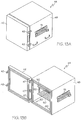
- FIGs. 13A-13E are schematic views of the frontloader chamber 44 in accordance with an embodiment of the invention. Specifically, FIG. 13A is a schematic view of the frontloader chamber 44 in a closed position. FIG. 13B is a schematic view of the frontloader chamber 44 in an open position. FIG. 13C is a schematic top view of the frontloader chamber 44. FIG. 13D is a schematic rear view of the frontloader chamber 44. FIG. 13E is a schematic side view of the frontloader chamber 44.
- the frontloader chamber 44 can include various types of shelving on which the user places the device being thermally tested.
- the device being tested could be a printed circuit board, mechanical or electronic module or any other device requiring thermal test.
- the shelving 50 is generally located in horizontal planes allowing the temperature-controlled air to flow over the device(s) being tested before it exits the frontloader chamber 44.
- the shelving 50 is attached to the frontloader chamber 44 by a mounting device 53.
- the mounting device 53 has multiple notches, such that the shelves 50 can be inserted into the mounting device at multiple locations or include multiple shelves 50. As shown in FIG.
- the exhaust ports areas 60 are shown, in FIG. 13B , in the four forward corners but could be at other locations to optimize thermal performance.
- the exhaust is internally routed to the rear of the frontloader chamber 44 through rear exhaust port 62.
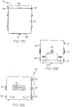
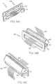
- FIGs. 14A-14H are schematic views of a self-closing cable feed-through module 64 in accordance with an embodiment of the invention.
- the self-closing cable feed-through module 64 of the invention can be used in connection with the frontloader chamber 44, as shown in FIG. 14F , in connection with the clamshell chamber 30, as shown in FIG. 14G , and in connection with the hood chamber 12, as shown in FIG. 14H , or in connection with any other standard temperature chamber or other yet undefined chamber configurations.
- FIG. 14A is a detailed schematic view of section A of FIG. 14F , illustrating the cable feed-through module 64 used with the frontloader chamber 44, as an example.
- the self-closing cable feed-through module 64 provides a convenient way for passing cables 66 from the exterior of a chamber to the interior of a chamber.
- the cables 66 referred to can be for any purpose to support the requirements of the device being temperature tested in the chamber.
- the cables 66 connect the device being tested inside the chamber to a test system that is used to send and/or receive data from the device being tested in the chamber.
- the self-closing cable feed-through module 64 is removable from the chamber for installation of the cables 66.
- the cables 66 are routed through a first half 68 and a second half 70 of the self-closing cable feed-through module 64.
- the self-closing cable feed-through module 64 is then installed into the chamber wall and, when installed, the first half 68 and the second half 70 close tightly and form a leak-tight seal around the cables, as shown in FIGs. 14A , 14D and 14E .
- the self-closing cable feed-through module 64 is secured in place with clamps 74 as shown in FIGs. 14A and 14E or by any other suitable means.
- a dry air source 76 provides dry air to self-closing cable feed-through module 64 to ensure that there is no moisture/frost formation during cold temperature operation.
- the self-closing cable feed-through module 64 is connected to an outer surface of a chamber. When the self-closing cable feed-through module 64 is in an open position, as shown in FIGs. 14B and 14C , the first half 68 and the second half are separated by rotating the second half 70 relative to the first half about joint 72.
- self-closing cable feed-through module 64 When the self-closing cable feed-through module 64 is in the open position, the cables 66 are fed through the first and second halves 68 and 70 into the chamber. When the self-closing cable feed-through module 64 is in a closed position, first and second portions are closed and form a leak tight seal around the cables 66, as shown in FIGs. 14A , 14D and 14E . As shown in FIGs. 14A, 14B and 14D-14H , self-closing cable feed-through module 64 includes a pull handle 78. FIG. 14E is a cross-sectional view along section B-B of FIG. 14D . As shown in FIG. 14D , the self-closing cable feed-through module 64 includes insulation 80.
Landscapes
- Engineering & Computer Science (AREA)
- Physics & Mathematics (AREA)
- Chemical & Material Sciences (AREA)
- Chemical Kinetics & Catalysis (AREA)
- Health & Medical Sciences (AREA)
- Clinical Laboratory Science (AREA)
- General Physics & Mathematics (AREA)
- Mechanical Engineering (AREA)
- Thermal Sciences (AREA)
- General Engineering & Computer Science (AREA)
- Combustion & Propulsion (AREA)
- Testing Resistance To Weather, Investigating Materials By Mechanical Methods (AREA)
- Other Air-Conditioning Systems (AREA)
Description
- This application claims the benefit of United States Provisional Application Serial No.
60/784,044, filed March 20, 2006 60/784,745, filed March 22, 2006 - This invention relates generally to a temperature-controlled enclosure for connecting to a source of temperature-controlled fluid, such as air, and a system including the enclosure and the source. This invention relates in particular to a temperature-controlled chamber that includes thermal insulation, a means of directing air to a device being tested, an exhausting system and a self-closing cable feed-through module.
- There are many manufacturers of standard temperature chambers. In general, in such chambers, air is circulated in a closed loop with a fan or blower directing the air over a heating and/or cooling coil to condition the temperature of the air before it enters a test area. The air then exits the test area and is again directed over the heating and/or cooling coil to condition the temperature of the air before it reenters the test area. These steps are repeated. The standard temperature chambers simply circulate the air with no method for directing the air to the device being tested. In addition, the standard temperature chambers use a metal (or other material) liner inside the chamber. The metal liner acts as a thermal load and significantly increases the time to transition between set temperatures.
-
US 5 271 230 discloses an apparatus and method for lowering the temperature within a chamber from a higher actual value to a set desired lower value, the latter being stabilized by intermittently flowing liquid gas, selectively, through the chamber and a venting orifice, under the control of a microcomputer responding to a temperature sensor within the chamber. -
US 6 098 473 discloses an air chamber which has Milli-Kelvin temperature control. This is achieved by the use of coarse and fine temperature control systems, and through the use of a structure for handling air flow within the chamber. The coarse control system provides enough heating or cooling power to hold the chamber temperature at a value near, but below, the desired operating temperature, thus leaving a small differential to be made up by the fine control loop. - According to the invention, there is provided a chamber in which a device can be located, the chamber being connectable to a temperature-controlled source for providing a temperature-controlled fluid to the chamber to control temperature of the chamber; and a self-closing cable feed-through module connected to an outer surface of the chamber, the module comprising a first portion and a second portion, wherein cables are fed through the first and second portions into the chamber in a first position of the module and the first and second portions form a leak tight seal around the cables in a second position of the module.
- Preferably, the temperature chamber further comprises an exhaust system for exhausting the fluid from the chamber.
- Conveniently, the exhaust system comprises a plurality of exhaust ports connected internal to the chamber and a single outlet port for allowing the fluid to exit the chamber.
- Preferably, the exhaust system comprises a plurality of exhaust ports connected internal to the chamber and multiple outlet ports for allowing the fluid to exit the chamber.
- Conveniently, the exhaust system comprises an exhaust port centrally located in the bottom of the chamber and an outlet port for allowing the fluid to exit the rear of the chamber.
- Preferably, a location of an exhaust is selectable by a user.
- Conveniently, the temperature chamber further comprises thermal insulation material formed on side surfaces of the chamber.
- Preferably, the chamber has a hood configuration.
- Conveniently, a thin layer of silicone is bonded to the surface of the thermal insulation material.
- Preferably, the thermal insulation material is positioned between an outer shell of the chamber and an inner liner of the chamber.
- Conveniently, the inner liner of the chamber is thermally decoupled from the outer shell.
- Preferably, the chamber has a clamshell configuration in which a top portion of the chamber is connected to a bottom portion of the chamber such that the top portion is opened in order to load the device into the chamber.
- Conveniently, the chamber has a front-loader configuration in which a front portion of the chamber is connected to a rear portion of the chamber such that the front portion is opened in order to load the device into the chamber.
- Preferably, the fluid is air.
- Conveniently, the temperature chamber further comprises a universal manifold adaptor for directing the temperature-controlled fluid directly to the device.
- Preferably, interchangeable manifolds are attachable to the universal manifold to direct the fluid to the device.
- Conveniently, a manifold comprises a single horizontal tube with multiple small holes for discharge of the fluid.
- Preferably, a manifold comprises a plurality of horizontal tubes with multiple small holes for discharge of the fluid.
- Conveniently, a manifold has a shower-head configuration to provide uniform distribution of the fluid.
- Preferably, a manifold comprises a baffle system.
- Conveniently, the self-closing cable feed-through module is removable from the chamber.
- Preferably, the self-closing cable feed-through module is installed into a wall of the chamber, and clamps secure the self-closing cable feed-through module to the chamber.
- Conveniently, the temperature chamber further comprises a dry air source for providing dry air to the self-closing cable feed-through module.
- Preferably, the self-closing cable feed-through module comprises a joint for rotating the second portion relative to the first portion.
- Conveniently, the self-closing cable feed-through module further comprises insulation. Preferably, the chamber is connected to a temperature-controlled source for providing a temperature-controlled fluid to the chamber to control temperature of the chamber;
- The foregoing and other objects, features and advantages of the invention will be apparent from the more particular description of preferred aspects of the invention, as illustrated in the accompanying drawings in which like reference characters refer to the same parts throughout the different views. The drawings are not necessarily to scale, emphasis instead being placed upon illustrating the principles of the invention.
-
FIG. 1 is a schematic perspective view of a hood chamber connected to a temperature-controlled air source in accordance with an embodiment of the invention. -
FIGs. 2A-2E are schematic views of the hood chamber ofFIG. 1 with a universal manifold adapter in accordance with an embodiment of the invention. -
FIG. 3 is a schematic perspective view of the hood chamber ofFIG. 1 in accordance with an embodiment of the invention. -
FIG. 4 is a schematic perspective view of the hood chamber ofFIG. 1 in accordance with an embodiment of the invention. -
FIGs. 5A and 5B are schematic perspective views of a clamshell chamber connected to a temperature-controlled air source in accordance with an embodiment of the invention. -
FIGs. 6A-6D are schematic views of the clamshell chamber ofFIGs. 5B and 5B in accordance with an embodiment of the present invention.FIG. 6E is a schematic cross-sectional view of the clamshell chamber in accordance with an embodiment of the present invention. -
FIGs. 7A-C are schematic views of the clamshell chamber ofFIGs. 5A and 5B with a universal manifold adapter in accordance with an embodiment of the invention. -
FIGs. 8A and 8B are schematic perspective view of a frontloader chamber connected to a temperature-controlled air source in accordance with an embodiment of the invention. -
FIGs. 9A and 9B are schematic perspective views of the frontloader chamber ofFIGs. 8A and 8B connected to a temperature-controlled air source in accordance with an embodiment of the invention. -
FIGs. 10A and 10B are schematic perspective view of the frontloader chamber ofFIGs. 8A and 8B connected to a temperature-controlled air source in accordance with an embodiment of the invention. -
FIG. 11 is an exploded perspective view of the frontloader chamber ofFIGs. 8A and 8B in accordance with an embodiment of the invention. -
FIGs. 12A and 12B are schematic views of the frontloader chamber ofFIGs. 8A and 8B with a universal manifold adapter in accordance with an embodiment of the invention. -
FIGs. 13A-13E are schematic views of the frontloader chamber ofFIGs. 8A and 8B in accordance with an embodiment of the invention. -
FIGs. 14A-14H are schematic views of a self-closing cable feed-through module in accordance with an embodiment of the invention. - According to the invention, a source of temperature-controlled fluid such as air, for example, ThermoStream™ model TP04300 or TP04310, manufactured and sold by Temptronic Corporation of Sharon, Massachusetts, is used as an open-loop temperature source for controlling the temperature within a temperature chamber. The source is either attached directly to the inlet of the temperature chamber or there is a flexible air transfer line, i.e., a flexible extender, that connects a source head to the temperature chamber inlet. The temperature-controlled air exhausts out of the temperature chamber. According to the invention, it is possible to connect the temperature-controlled air source (one at a time) to several different temperature chamber configurations, thus providing an economical solution when several different temperature chamber configurations are required. The device being tested in the temperature chamber could be a printed circuit board, mechanical or electronic module or any other device requiring thermal test. In addition, the source can be used as a temperature source for temperature testing various devices without attaching to a temperature chamber.
- The present invention includes a family of interchangeable temperature chambers for . use with the source, i.e., the open-loop temperature source. The features of the chambers include a highly efficient thermal insulation design that provides overall improvement in thermal performance by minimizing heat loss and reducing thermal loads, a highly efficient and field changeable method of air distribution for improved thermal response for specific testing applications, unique air exhaust systems for optimizing temperature uniformity, and a self-closing cable feed-through module.
- In a first embodiment of the present invention, the chamber is of a hood configuration.
FIG. 1 is a schematic perspective view of ahood chamber 12 according to an embodiment of the invention connected to asource 10 of temperature-controlled fluid such as air. Thesource 10 can be, for example, a ThermoStream™ model TP04300 or TP04310, manufactured and sold by Temptronic Corporation of Sharon, Massachusetts, or other similar device. Thesource 10 is used as the temperature-controlled air source for controlling the temperature within thehood chamber 12. Ahead 14 of thesource 10 attaches directly to the top side of thehood chamber 12 with three knurled screws. No tools are required to attach thehead 14 to thehood chamber 12. Thehead 14 is attached to thesource 10 by a pivotingarm 15. -
FIGs. 2A-2E are schematic views of thehood chamber 12 ofFIG. 1 with auniversal manifold adapter 20 in accordance with an embodiment of the invention. Thehood chamber 12 is provided with theuniversal manifold adapter 20 designed to improve temperature response which reduces time for completion of a test and, therefore, reduces the test cost. Theuniversal manifold adapter 20 allows interchangeable manifolds to be used to optimize temperature testing.FIGs. 2A-2E illustrate the interchangeable manifolds. To optimize thermal performance it is desirable that the temperature-controlled air being supplied by thesource 10 be directed to the device being tested. Conventional thermal enclosures (chambers) simply circulate the air with no method for directing the air to the device being tested. With theuniversal manifold adapter 20 in thehood chamber 12, a manifold can be added to direct the temperature-controlled air directly to the device being tested. - The
universal manifold adapter 20 allows the air distribution manifold to be changed to a different configuration if necessary to accommodate changes in test requirements within thesame hood chamber 12.FIG. 2A is a schematic view of thehood 12 with theuniversal manifold adaptor 20 with no manifolds attached thereto. Theuniversal manifold adapter 20 has several attachment points (holes) that allow attachment of interchangeable manifolds. The manifold can be a singlehorizontal tube 22 with multiple small holes for air discharge. The manifold can be two or morehorizontal tubes 22.FIG. 2B is a schematic view of thehood chamber 12 with twohorizontal tubes 22 with multiple small holes for air discharge attached to theuniversal manifold adapter 20. The manifold can be a piece of flexible tube to better direct air on the device being tested. The manifold can be a shower head type to provide uniform distribution of temperature-controlled air, or any other manifold for distribution of temperature-controlled air.FIG. 2C is a schematic view of thehood chamber 12 with a shower-head type manifold 24 attached to theuniversal manifold adaptor 20.FIG. 2D is a schematic view of thehood chamber 12 with a shower-head type manifold 24 attached to theuniversal manifold adaptor 20 andexhaust ports 26 at side portions of thehood chamber 12.FIG. 2E is a schematic view of thehood chamber 12 with a shower-head manifold 24 and fourhorizontal tubes 22 with multiple small holes for air discharge attached to theuniversal manifold adaptor 20. -
FIG. 3 is a schematic perspective view of thehood chamber 12 ofFIG. 1 in accordance with an embodiment of the invention. The thermal insulation design used for thehood chamber 12 as shown inFIG. 3 allows temperature changes to occur much faster than with existing approaches. Thehood chamber 12 includes a layer ofthermal insulation 16 with a thin layer ofsilicone 18 bonded to the surface of theinsulation 16. The bondedlayer 18 provides needed protection against damage to theinsulation 16. The bondedlayer 18 eliminates the need for a metal (or other material) liner inside thehood chamber 12, which would act as a thermal load and significantly increase the time to transition between set temperatures. Thehood chamber 12 includes ahandle 23. -
FIG. 4 is a schematic perspective view of thehood chamber 12 ofFIG. 1 in accordance with an embodiment of the invention. InFIG. 4 , thehood chamber 12 is disconnected from theair source 10. An air-inconnection 25 is used to connect to thesource 10. - The
hood chamber 12 also incorporates a unique air exhausting system to optimize temperature uniformity within the test area. All hood chamber configurations provide multiple exhaust areas within the test areas to ensure uniform air distribution throughout the test area. The exhaust areas are typically located in side portions of thehood chamber 12 but can be in other locations if necessary to optimize uniformity. As shown inFIG. 2D andFIG. 3 ,exhaust ports 26 are located at side portions of the hood chamber. 12. As shown inFIG. 2D andFIG. 3 , all of theexhaust ports 26 are connected internal to thehood chamber 12 with only oneexit exhaust 28 exiting thehood chamber 12 being used in a selected configuration.Internal route 27 is the route of the exhaust in thehood chamber 12. The exhaust location is user selectable (first andsecond exit ports 28, which are 90 degrees apart) for test operator convenience. Thehood chamber 12 includes ahandle 23. - In an alternative embodiment, the chamber is of a clamshell configuration.
FIGs. 5A and 5B are schematic perspective views of aclamshell chamber 30 connected to thesource 10, in accordance with an embodiment of the invention. Theclamshell chamber 30 is top-loaded such that the device being tested is loaded into the chamber from the top. InFIGs. 5A and 5B , asource 10 is used as the temperature-controlled air source for controlling the temperature within theclamshell chamber 30. InFIG. 5A , thehead 14 of thesource 10 attaches to the side of theclamshell chamber 30 via aflex extender 32 which transfers the temperature-controlled air from thesource 10 to theclamshell chamber 30. InFIG. 5A , thehead 14 is connected to a pivotingarm 15. InFIG. 5B , the output of thesource 10 attaches to the side of theclamshell chamber 30 via theflex extender 32 which transfers the temperature-controlled air from thesource 10 to theclamshell chamber 30. Attachment of theflex extender 32 to theclamshell chamber 30 is made with three knurled screws. No tools are required to attach theflex extender 32 to theclamshell chamber 30. The attachment can be made to either side of the clamshell chamber for convenience. -
FIGs. 6A-6E are schematic views of aclamshell chamber 30 ofFIGs. 5A and 5B in accordance with an embodiment of the present invention. Specifically,FIG. 6A is a schematic top view of theclamshell chamber 30.FIG. 6B is a schematic rear view of theclamshell chamber 30.FIG. 6C is a schematic front view ofclamshell chamber 30.FIG. 6D is a schematic view of theclamshell chamber 30 in an open position.FIG. 6E is a schematic cross-sectional view of theclamshell chamber 30 along section E-E ofFIG. 6A in accordance with an embodiment of the present invention. - The
clamshell chamber 30 includes atop portion 34 connected to abottom portion 36 by a hinges 35. When theclamshell chamber 30 is closed, the top andbottom portions clamshell 30 includes four cable feed-throughopenings 41 for connecting cables to the interior of theclamshell chamber 30 on each side of theclamshell chamber 30. - The thermal insulation design used for the
clamshell chamber 30 and as shown inFIG. 6E allows temperature changes to occur much faster than with existing approaches. Theclamshell chamber 30 usesthermal insulation 43, i.e., foam, between theouter shell 37 of theclamshell chamber 30 and theinner liner 39 of theclamshell chamber 30. Theinner liner 39 protects theinsulation 43 from damage that might result from frequent use. Theinner liner 39 is thermally decoupled from theouter shell 37 to minimize thermal losses and optimize thermal performance, i.e., temperature response and temperature uniformity. In one embodiment, theinner liner 39 is made of very thin stainless steel to minimize thermal load, but could be other suitable materials. -
FIGs. 7A-7C are schematic views of theclamshell chamber 30 ofFIGs. 5A and 5B with auniversal manifold adapter 20 in accordance with an embodiment of the invention. Theclamshell chamber 30 is provided with theuniversal manifold adapter 20 to improve temperature response which reduces time for completion of a test and, therefore, reduces test cost. Theuniversal manifold adapter 20 allows interchangeable manifolds to be used to optimize temperature testing. To optimize thermal performance it is desirable that the temperature-controlled air being supplied by thesource 10 be directed to the device being tested. Conventional thermal enclosures (chambers) simply circulate the air with no method for directing the air to the device being tested. With theuniversal manifold adapter 20 in theclamshell chamber 30, a manifold can be added to direct the temperature-controlled air directly to the device being tested. - The
universal manifold adapter 20 allows the air distribution manifold to be changed to a different configuration if necessary to accommodate changes in test requirements within the same clamshell chamber. Theuniversal manifold adapter 20 has several attachment points (holes) that allow attachment of interchangeable manifolds. The manifold can be a singlehorizontal tube 22 with multiple small holes for air discharge. The manifold can be two or morehorizontal tubes 22.FIG. 7A is a schematic diagram of theclamshell chamber 30 with twohorizontal tubes 22 with multiple small holes for air discharge attached to theuniversal manifold adapter 20. The manifold can be a piece of flexible tube to better direct air on the device being tested. The manifold can be a shower-head type to provide uniform distribution of temperature-controlled air, or any other manifold for distribution of temperature-controlled air.FIG. 7B is a schematic diagram of theclamshell chamber 30 with a shower-head type manifold 24 attached to theuniversal manifold adaptor 20.FIG. 7C is a schematic diagram of theclamshell chamber 30 with a shower-head type manifold 24 and fourhorizontal tubes 22 with multiple small holes for air discharge attached to theuniversal manifold adaptor 20. - The
clamshell chamber 30 also incorporates a unique air exhausting system to optimize temperature uniformity within the test area. Theclamshell chamber 30 includes a mountingplatform 38, as shown inFIG. 6E on which the user places the device being thermally tested. The device being tested could be a printed circuit board, mechanical or electronic module or any other device requiring thermal test. The mountingplatform 38 is located above an exhaust port 40, which is centrally located in the bottom of theclamshell chamber 30, so that all of the temperature-controlled air entering theclamshell chamber 30 through the air-inport 45 flows over the device being tested before it exits theclamshell chamber 30. This arrangement optimizes temperature uniformity within theclamshell chamber 30 as well as temperature response, i.e., changing set point temperatures is faster. The exhaust is internally routed to the rear of the clamshell chamber to arear exhaust 42, as shown inFIGs. 6B and6E . - In
FIGs. 8A, 8B ,9A, 9B ,10A and 10B , asource 10 is used as the temperature-controlled air source for controlling the temperature within afrontloader chamber 44, in accordance with another embodiment of the invention.FIGs. 8A and 8B are schematic perspective views of thefrontloader chamber 44 connected to asource 10, in accordance with the invention. InFIGs. 8A and 8B , thehead 14 of thesource 10 attaches to the rear of thefrontloader chamber 44 either directly or via aflex extender 32 which transfers the temperature-controlled air from thesource head 14 to thefrontloader chamber 44. InFIGs. 8A and 8B , thehead 14 is attached to thesource 10 by a pivotingarm 15.FIGs. 9A and 9B are schematic perspective views of thefrontloader chamber 44 connected to asource 10, in accordance with another embodiment of the invention. InFIGs. 9A and 9B , the output of thesource 10 is attached to the rear of the frontloadedchamber 44 via aflex extender 32 which transfers the temperature-controlled air from thesource 10 to thefrontloader chamber 44.FIGs. 10A and 10B are schematic perspective views of thefrontloader chamber 44 connected to asource 10, in accordance with another embodiment of the invention. InFIGs. 10A and 10B , thefrontloader chamber 44 is directly docked to the top of thesource 10. - Referring to
FIGs. 8A, 8B ,9A, 9B ,10A and 10B , thefrontloader chamber 44 includes afront portion 46 connected to arear portion 48 by ahinge 47. When thefrontloader chamber 44 is in the closed position, latches 49 latch the front andrear portions frontloader chamber 44 has cable feed-through 51 for connecting cables to the interior of thefrontloader chamber 44. -
FIG. 11 is an exploded perspective view of thefrontloader chamber 44 ofFIGs. 8A and 8B in accordance with an embodiment of the invention. The thermal insulation design used for thefrontloader chamber 44, as shown inFIG. 11 allows temperature changes to occur much faster than with existing approaches. Thefrontloader chamber 44 usesthermal insulation 54 between theouter shell 56 of thefrontloader chamber 44 and theinner liner 52 of thefrontloader chamber 44. Theinner liner 52 protects theinsulation 54 from damage that might result from frequent use. However, theinner liner 52 is thermally decoupled from theouter shell 56 to minimize thermal losses and optimize thermal performance, i.e., temperature response and temperature uniformity. In one embodiment, theinner liner 52 is made of very thin stainless steel to minimize thermal load, but could be other suitable materials. -
FIGs. 12A and 12B are schematic views of thefrontloader chamber 44 with auniversal manifold adapter 20 in accordance with an embodiment of the invention. InFIGs. 12A and 12B , thefrontloader chamber 44 is provided with theuniversal manifold adapter 20 designed to improve temperature response which reduces time for completion of a test and, therefore, reduces test cost. Theuniversal manifold adapter 20 allows interchangeable manifolds to be used to optimize temperature testing. To optimize thermal performance it is desirable that the temperature-controlled air being supplied by thesource 10 be directed to the device being tested. Conventional thermal enclosures (chambers) simply circulate the air with no method for directing the air to the device being tested. With theuniversal manifold adapter 20 in thefrontloader chamber 44, a manifold can be added to direct the temperature-controlled air directly to the device being tested. - The
universal manifold adapter 20 allows the air distribution manifold to be changed to a different configuration if necessary to accommodate changes in test requirements within thesame frontloader chamber 44. Theuniversal manifold adapter 20 has several attachment points (holes) that allow attachment of interchangeable manifolds. The manifold can be asingle tube 22 with multiple small holes for air discharge. The manifold can be two ormore tubes 22 with multiple small holes for air discharge. The manifold can be a piece of flexible tube to better direct air on the device being tested. The manifold can be a shower-head type manifold to provide uniform distribution of temperature-controlled air.FIG. 12A , is a schematic diagram of thefrontloader chamber 44 with a shower-head type manifold 24 and fourhorizontal tubes 22 with multiple small holes for air discharge attached to theuniversal manifold adapter 20. The manifold can be abaffle system 58, as shown inFIG. 12B , in which a plate uniformly distributes temperature-controlled air over a large area or any other manifold for distribution of temperature-controlled air. - The
frontloader chamber 44 also incorporates a unique air exhausting system to optimize temperature uniformity within the test area.FIGs. 13A-13E are schematic views of thefrontloader chamber 44 in accordance with an embodiment of the invention. Specifically,FIG. 13A is a schematic view of thefrontloader chamber 44 in a closed position.FIG. 13B is a schematic view of thefrontloader chamber 44 in an open position.FIG. 13C is a schematic top view of thefrontloader chamber 44.FIG. 13D is a schematic rear view of thefrontloader chamber 44.FIG. 13E is a schematic side view of thefrontloader chamber 44. Thefrontloader chamber 44 can include various types of shelving on which the user places the device being thermally tested. The device being tested could be a printed circuit board, mechanical or electronic module or any other device requiring thermal test. In the preferred embodiment, as shown inFIGs. 12A, 12B and13B , theshelving 50 is generally located in horizontal planes allowing the temperature-controlled air to flow over the device(s) being tested before it exits thefrontloader chamber 44. Theshelving 50 is attached to thefrontloader chamber 44 by a mountingdevice 53. The mountingdevice 53 has multiple notches, such that theshelves 50 can be inserted into the mounting device at multiple locations or includemultiple shelves 50. As shown inFIG. 13D , air enters the rear of thefrontloader chamber 44 through the air-inport 61 and flows forward to four or moreexhaust ports areas 60 located so as to optimize thermal response and temperature uniformity within thefrontloader chamber 44. Theexhaust ports areas 60 are shown, inFIG. 13B , in the four forward corners but could be at other locations to optimize thermal performance. The exhaust is internally routed to the rear of thefrontloader chamber 44 throughrear exhaust port 62. -
FIGs. 14A-14H are schematic views of a self-closing cable feed-throughmodule 64 in accordance with an embodiment of the invention. The self-closing cable feed-throughmodule 64 of the invention can be used in connection with thefrontloader chamber 44, as shown inFIG. 14F , in connection with theclamshell chamber 30, as shown inFIG. 14G , and in connection with thehood chamber 12, as shown inFIG. 14H , or in connection with any other standard temperature chamber or other yet undefined chamber configurations. -
FIG. 14A is a detailed schematic view of section A ofFIG. 14F , illustrating the cable feed-throughmodule 64 used with thefrontloader chamber 44, as an example. The self-closing cable feed-throughmodule 64 provides a convenient way for passingcables 66 from the exterior of a chamber to the interior of a chamber. Thecables 66 referred to can be for any purpose to support the requirements of the device being temperature tested in the chamber. Thecables 66 connect the device being tested inside the chamber to a test system that is used to send and/or receive data from the device being tested in the chamber. The self-closing cable feed-throughmodule 64 is removable from the chamber for installation of thecables 66. Thecables 66 are routed through afirst half 68 and asecond half 70 of the self-closing cable feed-throughmodule 64. The self-closing cable feed-throughmodule 64 is then installed into the chamber wall and, when installed, thefirst half 68 and thesecond half 70 close tightly and form a leak-tight seal around the cables, as shown inFIGs. 14A ,14D and 14E . - The self-closing cable feed-through
module 64 is secured in place withclamps 74 as shown inFIGs. 14A and14E or by any other suitable means. A dry air source 76 provides dry air to self-closing cable feed-throughmodule 64 to ensure that there is no moisture/frost formation during cold temperature operation. The self-closing cable feed-throughmodule 64 is connected to an outer surface of a chamber. When the self-closing cable feed-throughmodule 64 is in an open position, as shown inFIGs. 14B and 14C , thefirst half 68 and the second half are separated by rotating thesecond half 70 relative to the first half about joint 72. When the self-closing cable feed-throughmodule 64 is in the open position, thecables 66 are fed through the first andsecond halves module 64 is in a closed position, first and second portions are closed and form a leak tight seal around thecables 66, as shown inFIGs. 14A ,14D and 14E . As shown inFIGs. 14A, 14B and14D-14H , self-closing cable feed-throughmodule 64 includes apull handle 78.FIG. 14E is a cross-sectional view along section B-B ofFIG. 14D . As shown inFIG. 14D , the self-closing cable feed-throughmodule 64 includesinsulation 80.
Claims (5)
- A temperature chamber, comprising:a chamber (12; 30; 44) in which a device can be located, the chamber being connectable to a temperature-controlled source (10) for providing a temperature-controlled fluid to the chamber to control temperature of the chamber; and characterized by a self-closing cable feed-through module (64) connected to an outer surface (56) of the chamber, the module comprising a first portion (68) and a second portion (70), wherein cables (66) are fed through the first (68) and second (70) portions into the chamber in a first position of the module and the first (68) and second (70) portions form a leak tight seal around the cables (66) in a second position of the module.
- The temperature chamber of claim 1, further comprising an exhaust system (26, 28) for exhausting the fluid from the chamber.
- The temperature chamber of claim 2, and any of:(a) wherein the exhaust system comprises a plurality of exhaust ports connected internal to the chamber and a single outlet port (28) for allowing the fluid to exit the chamber;(b) wherein the exhaust system comprises a plurality of exhaust ports connected internal to the chamber and multiple outlet ports (28) for allowing the fluid to exit the chamber;(c) wherein the exhaust system comprises an exhaust port centrally located in the bottom of the chamber (62) and an outlet port for allowing the fluid to exit the rear of the chamber; and(d) wherein a location of an exhaust (26, 28) is selectable by a user.
- The temperature chamber of claim 1, and any of:(a) further comprising thermal insulation material formed on side surfaces of the chamber, in which case, optionally either:(i) wherein the chamber has a hood configuration (12), in which case, further optionally, wherein a thin layer of silicone (18) is bonded to the surface of the thermal insulation material; or(ii) wherein the thermal insulation material (54) is positioned between an outer shell (56) of the chamber and an inner liner (52) of the chamber, in which case, further optionally, wherein the inner liner (52) of the chamber is thermally decoupled from the outer shell (56), in which case, yet further optionally, either wherein the chamber has a clamshell configuration (30) in which a top portion (34) of the chamber is connected to a bottom portion (36) of the chamber such that the top portion (34) is opened in order to load the device into the chamber, or wherein the chamber has a front-loader configuration (44) in which a front portion (46) of the chamber is connected to a rear portion (48) of the chamber such that the front portion (46) is opened in order to load the device into the chamber, or(b) wherein the fluid is air;(c) further comprising a universal manifold adaptor (20) for directing the temperature-controlled fluid directly to the device, in which case, optionally, wherein interchangeable manifolds are attachable to the universal manifold to direct the fluid to the device, in which case, further optionally, any of:(a) wherein a manifold comprises a single horizontal tube (22) with multiple small holes for discharge of the fluid;(b) wherein a manifold comprises a plurality of horizontal tubes (22) with multiple small holes for discharge of the fluid;(c) wherein a manifold has a shower-head (24) configuration to provide uniform distribution of the fluid; and(d) wherein a manifold comprises a baffle system (58).(e) wherein the self-closing cable feed-through module (64) is removable from the chamber;(f) wherein the self-closing cable feed-through module is installed into a wall of the chamber (56), and clamps (74) secure the self-closing cable feed-through module to the chamber;(g) further comprising a dry air source (76) for providing dry air to the self-closing cable feed-through module;(h) wherein the self-closing cable feed-through module comprises a joint (72) for rotating the second portion (70) relative to the first portion (68).(i) wherein the self-closing cable feed-through module further comprises insulation (80).
- The temperature chamber of claim 1, wherein the chamber is connected to a temperature-controlled source (10) for providing a temperature-controlled fluid to the chamber to control temperature of the chamber;
Applications Claiming Priority (3)
| Application Number | Priority Date | Filing Date | Title |
|---|---|---|---|
| US78404406P | 2006-03-20 | 2006-03-20 | |
| US78474506P | 2006-03-22 | 2006-03-22 | |
| PCT/US2007/006344 WO2007109027A1 (en) | 2006-03-20 | 2007-03-13 | Temperature-controlled enclosures and temperature control system using the same |
Publications (2)
| Publication Number | Publication Date |
|---|---|
| EP1996989A1 EP1996989A1 (en) | 2008-12-03 |
| EP1996989B1 true EP1996989B1 (en) | 2017-12-06 |
Family
ID=38169548
Family Applications (1)
| Application Number | Title | Priority Date | Filing Date |
|---|---|---|---|
| EP07753004.6A Not-in-force EP1996989B1 (en) | 2006-03-20 | 2007-03-13 | Temperature-controlled enclosures and temperature control system using the same |
Country Status (7)
| Country | Link |
|---|---|
| US (3) | US7629533B2 (en) |
| EP (1) | EP1996989B1 (en) |
| JP (1) | JP5123929B2 (en) |
| CN (1) | CN101443720B (en) |
| MY (1) | MY151524A (en) |
| TW (1) | TWI443489B (en) |
| WO (1) | WO2007109027A1 (en) |
Families Citing this family (15)
| Publication number | Priority date | Publication date | Assignee | Title |
|---|---|---|---|---|
| EP1894074A4 (en) * | 2005-06-13 | 2010-05-19 | Sigma Systems Corp | Methods and apparatus for optimizing environmental humidity |
| MY151524A (en) | 2006-03-20 | 2014-05-30 | Temptronic Corp | Temperature-controlled enclosures and temperature control system using the same |
| DE202008016919U1 (en) * | 2008-12-23 | 2009-03-05 | VLM GmbH-Innovative Korrosionsprüftechnik, Labortechnik und Dienstleistungen | Corrosion Testing rest |
| GB0919832D0 (en) * | 2009-11-13 | 2009-12-30 | Airbus Operations Ltd | Thermal test apparatus and method |
| CN102094848B (en) * | 2011-03-22 | 2013-02-27 | 上海交通大学 | Airfoils for large industrial high pressure ratio axial compressors |
| US20130181059A1 (en) * | 2012-01-13 | 2013-07-18 | Nissan North America, Inc. | Testing apparatus for preventing freezing of relays in electrical components |
| US8904888B2 (en) * | 2012-04-28 | 2014-12-09 | Mashhad University of Medical Sciences (MUMS) | Drinking simulator |
| TWD165448S (en) * | 2013-09-30 | 2015-01-11 | 愛斯佩克股份有限公司 | Parts of thermostat and hygrostat |
| TWI544300B (en) * | 2015-03-04 | 2016-08-01 | 旺矽科技股份有限公司 | Temperature controlling equipment |
| DE102016200538B4 (en) * | 2016-01-18 | 2017-12-28 | Weiss Umwelttechnik Gmbh | Klimaprüfgerät |
| US20170261547A1 (en) * | 2016-03-08 | 2017-09-14 | Temptronic Corporation | Temperature Forcing System and Method with Conductive Thermal Probes |
| USD869969S1 (en) * | 2017-12-28 | 2019-12-17 | Kokusai Keisokuki Kabushiki Kaisha | Testing device for tires |
| USD881730S1 (en) | 2018-05-02 | 2020-04-21 | Kokusai Keisokuki Kabushiki Kaisha | Testing device |
| US10790608B2 (en) * | 2018-11-13 | 2020-09-29 | Mellanox Technologies, Ltd. | Apparatuses for improved cable-to-board connections |
| JP7623236B2 (en) * | 2021-06-25 | 2025-01-28 | エスペック株式会社 | Temperature-controlled air supply device |
Family Cites Families (34)
| Publication number | Priority date | Publication date | Assignee | Title |
|---|---|---|---|---|
| US2692298A (en) * | 1952-04-29 | 1954-10-19 | Westinghouse Electric Corp | Tubulation and lead-in construction |
| US3422300A (en) * | 1966-06-30 | 1969-01-14 | Westinghouse Electric Corp | Ceramic arc tube and closure member construction |
| JPS60253884A (en) * | 1984-05-30 | 1985-12-14 | Mitsubishi Electric Corp | Constant temperature device |
| JPH036982Y2 (en) * | 1985-04-12 | 1991-02-21 | ||
| JPS6383724A (en) | 1986-09-29 | 1988-04-14 | Toshiba Corp | Electrophotographic sensitive body |
| JPS6383724U (en) * | 1986-11-20 | 1988-06-01 | ||
| US4860602A (en) * | 1988-05-18 | 1989-08-29 | Harris Corporation | RF transparent thermal test chamber |
| US5205969A (en) * | 1988-05-25 | 1993-04-27 | Signicast Corporation | Process for distributing a semi-solid wax to an injection press |
| DE3828693C1 (en) * | 1988-08-24 | 1989-10-26 | Plastoform Gmbh & Co Kg, 4973 Vlotho, De | |
| JPH02101251A (en) | 1988-10-04 | 1990-04-13 | Asahi Glass Co Ltd | Wall material fitting method for alc construction |
| JPH0733150Y2 (en) * | 1989-01-27 | 1995-07-31 | タバイエスペック株式会社 | Environmental test equipment |
| GB2248318B (en) * | 1990-09-06 | 1994-11-02 | Perkin Elmer Ltd | Temperature control systems |
| JPH0682354A (en) * | 1992-08-31 | 1994-03-22 | Tabai Espec Corp | Low/high temperature exposing test device |
| JP2516556B2 (en) | 1993-06-30 | 1996-07-24 | 日本ピラー工業株式会社 | Sealant made of heat-expandable inorganic fiber composite material |
| JP2565136Y2 (en) * | 1993-09-03 | 1998-03-11 | タバイエスペック株式会社 | Environmental test equipment with door with opening |
| US5692556A (en) * | 1994-01-14 | 1997-12-02 | Hafner; Erich | Precision temperature test chamber |
| US5722252A (en) * | 1995-10-13 | 1998-03-03 | Lg Electronics, Inc. | Cooling air distribution apparatus for refrigerator |
| GB2314702A (en) | 1996-06-28 | 1998-01-07 | Motorola Ltd | Detecting overheating of printed circuit boards |
| US5996370A (en) * | 1997-06-13 | 1999-12-07 | Lg Electronics, Inc. | Refrigeration compartment door for refrigerators |
| KR19990005697A (en) * | 1997-06-30 | 1999-01-25 | 배순훈 | Freezer Cold Air Supply Unit with Cross Flow Fan |
| US6189484B1 (en) * | 1999-03-05 | 2001-02-20 | Applied Materials Inc. | Plasma reactor having a helicon wave high density plasma source |
| US6315209B1 (en) * | 2000-03-01 | 2001-11-13 | Watts Regulator Company | Mixing valve |
| US6619566B2 (en) * | 2001-03-22 | 2003-09-16 | Nordson Corporation | Universal dispensing system for air assisted extrusion of liquid filaments |
| WO2003012567A1 (en) | 2001-07-30 | 2003-02-13 | Tokyo Electron Limited | Plasma chamber wall segment temperature control |
| CN1177188C (en) * | 2001-08-31 | 2004-11-24 | Lg电子株式会社 | Cooling air circulation unit in refrigerator |
| DE10224985B3 (en) * | 2002-06-05 | 2004-01-22 | Dietrich Menzel | Carrier with a cable duct for an electric light and method for its production |
| US6908512B2 (en) * | 2002-09-20 | 2005-06-21 | Blue29, Llc | Temperature-controlled substrate holder for processing in fluids |
| US7338637B2 (en) * | 2003-01-31 | 2008-03-04 | Hewlett-Packard Development Company, L.P. | Microfluidic device with thin-film electronic devices |
| US7568943B2 (en) * | 2005-07-27 | 2009-08-04 | Corning Cable Systems Llc | Sealing and retaining cable attachment for telecommunications closures |
| US7304251B1 (en) * | 2005-12-15 | 2007-12-04 | Arlington Industries, Inc. | Electrical fitting for snap in connection of cables |
| MY151524A (en) | 2006-03-20 | 2014-05-30 | Temptronic Corp | Temperature-controlled enclosures and temperature control system using the same |
| US7507907B2 (en) * | 2006-09-22 | 2009-03-24 | Lapp Engineering & Co. | Cable feed-through |
| US7411128B2 (en) * | 2006-09-26 | 2008-08-12 | Lapp Engineering & Co. | Cable feed-through and cable feed-through system |
| US9102833B2 (en) | 2011-12-16 | 2015-08-11 | Lintec Corporation | Curable resin composition, curable resin molded body, cured resin molded body, method for producing each of same, and laminate body |
-
2007
- 2007-03-13 MY MYPI20083682 patent/MY151524A/en unknown
- 2007-03-13 CN CN2007800168161A patent/CN101443720B/en not_active Expired - Fee Related
- 2007-03-13 JP JP2009501454A patent/JP5123929B2/en not_active Expired - Fee Related
- 2007-03-13 EP EP07753004.6A patent/EP1996989B1/en not_active Not-in-force
- 2007-03-13 WO PCT/US2007/006344 patent/WO2007109027A1/en not_active Ceased
- 2007-03-13 US US11/717,432 patent/US7629533B2/en not_active Expired - Fee Related
- 2007-03-19 TW TW096109253A patent/TWI443489B/en not_active IP Right Cessation
-
2009
- 2009-11-04 US US12/612,028 patent/US8408020B2/en not_active Expired - Fee Related
-
2013
- 2013-04-01 US US13/854,678 patent/US10060668B2/en active Active
Also Published As
| Publication number | Publication date |
|---|---|
| US20070240448A1 (en) | 2007-10-18 |
| EP1996989A1 (en) | 2008-12-03 |
| TWI443489B (en) | 2014-07-01 |
| CN101443720B (en) | 2012-01-11 |
| TW200805024A (en) | 2008-01-16 |
| WO2007109027A1 (en) | 2007-09-27 |
| MY151524A (en) | 2014-05-30 |
| US20100043485A1 (en) | 2010-02-25 |
| US7629533B2 (en) | 2009-12-08 |
| US10060668B2 (en) | 2018-08-28 |
| US8408020B2 (en) | 2013-04-02 |
| US20130231040A1 (en) | 2013-09-05 |
| CN101443720A (en) | 2009-05-27 |
| JP2009530588A (en) | 2009-08-27 |
| JP5123929B2 (en) | 2013-01-23 |
Similar Documents
| Publication | Publication Date | Title |
|---|---|---|
| US7629533B2 (en) | Temperature-controlled enclosures and temperature control system using the same | |
| US11178794B2 (en) | Computer server heat regulation utilizing integrated precision air flow | |
| AU2001259057B2 (en) | Computer rack heat extraction device | |
| US20030150231A1 (en) | Computer rack heat extraction device | |
| US7573713B2 (en) | High velocity air cooling for electronic equipment | |
| US6679128B2 (en) | Environmental test chamber | |
| US9002186B2 (en) | Controlling the temperature of an object | |
| CN102149810B (en) | Incubation system with low temperature enclosure | |
| JP7739034B2 (en) | System for microscopic examination of incubated samples | |
| EP1693117A3 (en) | Deposition device having a thermal control system | |
| US20170354064A1 (en) | Modular data center facility with cooling modules | |
| CN111751066A (en) | Environmental test apparatus, laboratory component, and environmental test method | |
| US6018614A (en) | Portable compressed air heater system | |
| US12303884B2 (en) | Microscope for microscopic examination of a sample | |
| JP2002519612A (en) | Anti-condensing low-temperature fluid transfer device and transfer method | |
| CN210784703U (en) | Portable auxiliary examination platform of electrocardiograph | |
| US20230304618A1 (en) | Quick-Disconnect Assembly For A Fluid Line In A Server | |
| JP2016170095A (en) | Gyro sensor characteristic measuring device | |
| Muller et al. | Giant Magellan Telescope primary mirror thermal control system design | |
| US12492968B2 (en) | Climate controlled housing for instrumentation | |
| CN218100024U (en) | Local heat preservation device for parts in environment box | |
| CN222364277U (en) | Heating element and liquid cooling equipment debugging frock | |
| CN121201401A (en) | A thermal load testing system and method for airborne equipment | |
| JP2559203B2 (en) | Radiant cooling system with ice heat storage tank | |
| KR20230056152A (en) | Ventilation system and method for electrical equipment room of vessel and vessel inculding the same |
Legal Events
| Date | Code | Title | Description |
|---|---|---|---|
| PUAI | Public reference made under article 153(3) epc to a published international application that has entered the european phase |
Free format text: ORIGINAL CODE: 0009012 |
|
| 17P | Request for examination filed |
Effective date: 20080918 |
|
| AK | Designated contracting states |
Kind code of ref document: A1 Designated state(s): AT BE BG CH CY CZ DE DK EE ES FI FR GB GR HU IE IS IT LI LT LU LV MC MT NL PL PT RO SE SI SK TR |
|
| DAX | Request for extension of the european patent (deleted) | ||
| 17Q | First examination report despatched |
Effective date: 20141028 |
|
| REG | Reference to a national code |
Ref country code: DE Ref legal event code: R079 Ref document number: 602007053286 Country of ref document: DE Free format text: PREVIOUS MAIN CLASS: G05D0023000000 Ipc: B01L0001000000 |
|
| GRAP | Despatch of communication of intention to grant a patent |
Free format text: ORIGINAL CODE: EPIDOSNIGR1 |
|
| STAA | Information on the status of an ep patent application or granted ep patent |
Free format text: STATUS: GRANT OF PATENT IS INTENDED |
|
| RIC1 | Information provided on ipc code assigned before grant |
Ipc: G01M 99/00 20110101ALI20170524BHEP Ipc: F25D 23/06 20060101ALI20170524BHEP Ipc: B01L 1/00 20060101AFI20170524BHEP Ipc: B01L 7/00 20060101ALI20170524BHEP |
|
| INTG | Intention to grant announced |
Effective date: 20170623 |
|
| GRAS | Grant fee paid |
Free format text: ORIGINAL CODE: EPIDOSNIGR3 |
|
| GRAA | (expected) grant |
Free format text: ORIGINAL CODE: 0009210 |
|
| STAA | Information on the status of an ep patent application or granted ep patent |
Free format text: STATUS: THE PATENT HAS BEEN GRANTED |
|
| AK | Designated contracting states |
Kind code of ref document: B1 Designated state(s): AT BE BG CH CY CZ DE DK EE ES FI FR GB GR HU IE IS IT LI LT LU LV MC MT NL PL PT RO SE SI SK TR |
|
| REG | Reference to a national code |
Ref country code: GB Ref legal event code: FG4D |
|
| REG | Reference to a national code |
Ref country code: AT Ref legal event code: REF Ref document number: 951896 Country of ref document: AT Kind code of ref document: T Effective date: 20171215 Ref country code: CH Ref legal event code: EP |
|
| REG | Reference to a national code |
Ref country code: IE Ref legal event code: FG4D |
|
| REG | Reference to a national code |
Ref country code: DE Ref legal event code: R096 Ref document number: 602007053286 Country of ref document: DE |
|
| REG | Reference to a national code |
Ref country code: FR Ref legal event code: PLFP Year of fee payment: 12 |
|
| REG | Reference to a national code |
Ref country code: NL Ref legal event code: MP Effective date: 20171206 |
|
| REG | Reference to a national code |
Ref country code: LT Ref legal event code: MG4D |
|
| PG25 | Lapsed in a contracting state [announced via postgrant information from national office to epo] |
Ref country code: ES Free format text: LAPSE BECAUSE OF FAILURE TO SUBMIT A TRANSLATION OF THE DESCRIPTION OR TO PAY THE FEE WITHIN THE PRESCRIBED TIME-LIMIT Effective date: 20171206 Ref country code: LT Free format text: LAPSE BECAUSE OF FAILURE TO SUBMIT A TRANSLATION OF THE DESCRIPTION OR TO PAY THE FEE WITHIN THE PRESCRIBED TIME-LIMIT Effective date: 20171206 Ref country code: FI Free format text: LAPSE BECAUSE OF FAILURE TO SUBMIT A TRANSLATION OF THE DESCRIPTION OR TO PAY THE FEE WITHIN THE PRESCRIBED TIME-LIMIT Effective date: 20171206 Ref country code: SE Free format text: LAPSE BECAUSE OF FAILURE TO SUBMIT A TRANSLATION OF THE DESCRIPTION OR TO PAY THE FEE WITHIN THE PRESCRIBED TIME-LIMIT Effective date: 20171206 |
|
| REG | Reference to a national code |
Ref country code: AT Ref legal event code: MK05 Ref document number: 951896 Country of ref document: AT Kind code of ref document: T Effective date: 20171206 |
|
| PG25 | Lapsed in a contracting state [announced via postgrant information from national office to epo] |
Ref country code: BG Free format text: LAPSE BECAUSE OF FAILURE TO SUBMIT A TRANSLATION OF THE DESCRIPTION OR TO PAY THE FEE WITHIN THE PRESCRIBED TIME-LIMIT Effective date: 20180306 Ref country code: LV Free format text: LAPSE BECAUSE OF FAILURE TO SUBMIT A TRANSLATION OF THE DESCRIPTION OR TO PAY THE FEE WITHIN THE PRESCRIBED TIME-LIMIT Effective date: 20171206 Ref country code: GR Free format text: LAPSE BECAUSE OF FAILURE TO SUBMIT A TRANSLATION OF THE DESCRIPTION OR TO PAY THE FEE WITHIN THE PRESCRIBED TIME-LIMIT Effective date: 20180307 |
|
| REG | Reference to a national code |
Ref country code: DE Ref legal event code: R082 Ref document number: 602007053286 Country of ref document: DE Representative=s name: STOLMAR & PARTNER PATENTANWAELTE PARTG MBB, DE Ref country code: DE Ref legal event code: R081 Ref document number: 602007053286 Country of ref document: DE Owner name: TEMPTRONIC CORPORATION, MANSFIELD, US Free format text: FORMER OWNER: TEMPTRONIC CORP., SHARON, MASS., US |
|
| RAP2 | Party data changed (patent owner data changed or rights of a patent transferred) |
Owner name: TEMPTRONIC CORPORATION |
|
| PG25 | Lapsed in a contracting state [announced via postgrant information from national office to epo] |
Ref country code: NL Free format text: LAPSE BECAUSE OF FAILURE TO SUBMIT A TRANSLATION OF THE DESCRIPTION OR TO PAY THE FEE WITHIN THE PRESCRIBED TIME-LIMIT Effective date: 20171206 |
|
| PG25 | Lapsed in a contracting state [announced via postgrant information from national office to epo] |
Ref country code: CZ Free format text: LAPSE BECAUSE OF FAILURE TO SUBMIT A TRANSLATION OF THE DESCRIPTION OR TO PAY THE FEE WITHIN THE PRESCRIBED TIME-LIMIT Effective date: 20171206 Ref country code: EE Free format text: LAPSE BECAUSE OF FAILURE TO SUBMIT A TRANSLATION OF THE DESCRIPTION OR TO PAY THE FEE WITHIN THE PRESCRIBED TIME-LIMIT Effective date: 20171206 Ref country code: SK Free format text: LAPSE BECAUSE OF FAILURE TO SUBMIT A TRANSLATION OF THE DESCRIPTION OR TO PAY THE FEE WITHIN THE PRESCRIBED TIME-LIMIT Effective date: 20171206 |
|
| PG25 | Lapsed in a contracting state [announced via postgrant information from national office to epo] |
Ref country code: IT Free format text: LAPSE BECAUSE OF FAILURE TO SUBMIT A TRANSLATION OF THE DESCRIPTION OR TO PAY THE FEE WITHIN THE PRESCRIBED TIME-LIMIT Effective date: 20171206 Ref country code: RO Free format text: LAPSE BECAUSE OF FAILURE TO SUBMIT A TRANSLATION OF THE DESCRIPTION OR TO PAY THE FEE WITHIN THE PRESCRIBED TIME-LIMIT Effective date: 20171206 Ref country code: AT Free format text: LAPSE BECAUSE OF FAILURE TO SUBMIT A TRANSLATION OF THE DESCRIPTION OR TO PAY THE FEE WITHIN THE PRESCRIBED TIME-LIMIT Effective date: 20171206 Ref country code: PL Free format text: LAPSE BECAUSE OF FAILURE TO SUBMIT A TRANSLATION OF THE DESCRIPTION OR TO PAY THE FEE WITHIN THE PRESCRIBED TIME-LIMIT Effective date: 20171206 |
|
| REG | Reference to a national code |
Ref country code: DE Ref legal event code: R097 Ref document number: 602007053286 Country of ref document: DE |
|
| PLBE | No opposition filed within time limit |
Free format text: ORIGINAL CODE: 0009261 |
|
| STAA | Information on the status of an ep patent application or granted ep patent |
Free format text: STATUS: NO OPPOSITION FILED WITHIN TIME LIMIT |
|
| REG | Reference to a national code |
Ref country code: CH Ref legal event code: PL |
|
| 26N | No opposition filed |
Effective date: 20180907 |
|
| GBPC | Gb: european patent ceased through non-payment of renewal fee |
Effective date: 20180313 |
|
| PG25 | Lapsed in a contracting state [announced via postgrant information from national office to epo] |
Ref country code: MC Free format text: LAPSE BECAUSE OF FAILURE TO SUBMIT A TRANSLATION OF THE DESCRIPTION OR TO PAY THE FEE WITHIN THE PRESCRIBED TIME-LIMIT Effective date: 20171206 Ref country code: DK Free format text: LAPSE BECAUSE OF FAILURE TO SUBMIT A TRANSLATION OF THE DESCRIPTION OR TO PAY THE FEE WITHIN THE PRESCRIBED TIME-LIMIT Effective date: 20171206 Ref country code: SI Free format text: LAPSE BECAUSE OF FAILURE TO SUBMIT A TRANSLATION OF THE DESCRIPTION OR TO PAY THE FEE WITHIN THE PRESCRIBED TIME-LIMIT Effective date: 20171206 |
|
| REG | Reference to a national code |
Ref country code: BE Ref legal event code: MM Effective date: 20180331 |
|
| REG | Reference to a national code |
Ref country code: IE Ref legal event code: MM4A |
|
| PG25 | Lapsed in a contracting state [announced via postgrant information from national office to epo] |
Ref country code: LU Free format text: LAPSE BECAUSE OF NON-PAYMENT OF DUE FEES Effective date: 20180313 |
|
| PG25 | Lapsed in a contracting state [announced via postgrant information from national office to epo] |
Ref country code: IE Free format text: LAPSE BECAUSE OF NON-PAYMENT OF DUE FEES Effective date: 20180313 |
|
| PG25 | Lapsed in a contracting state [announced via postgrant information from national office to epo] |
Ref country code: LI Free format text: LAPSE BECAUSE OF NON-PAYMENT OF DUE FEES Effective date: 20180331 Ref country code: CH Free format text: LAPSE BECAUSE OF NON-PAYMENT OF DUE FEES Effective date: 20180331 Ref country code: GB Free format text: LAPSE BECAUSE OF NON-PAYMENT OF DUE FEES Effective date: 20180313 Ref country code: BE Free format text: LAPSE BECAUSE OF NON-PAYMENT OF DUE FEES Effective date: 20180331 |
|
| PG25 | Lapsed in a contracting state [announced via postgrant information from national office to epo] |
Ref country code: MT Free format text: LAPSE BECAUSE OF NON-PAYMENT OF DUE FEES Effective date: 20180313 |
|
| PG25 | Lapsed in a contracting state [announced via postgrant information from national office to epo] |
Ref country code: TR Free format text: LAPSE BECAUSE OF FAILURE TO SUBMIT A TRANSLATION OF THE DESCRIPTION OR TO PAY THE FEE WITHIN THE PRESCRIBED TIME-LIMIT Effective date: 20171206 |
|
| PGFP | Annual fee paid to national office [announced via postgrant information from national office to epo] |
Ref country code: DE Payment date: 20200327 Year of fee payment: 14 |
|
| PG25 | Lapsed in a contracting state [announced via postgrant information from national office to epo] |
Ref country code: HU Free format text: LAPSE BECAUSE OF FAILURE TO SUBMIT A TRANSLATION OF THE DESCRIPTION OR TO PAY THE FEE WITHIN THE PRESCRIBED TIME-LIMIT; INVALID AB INITIO Effective date: 20070313 Ref country code: PT Free format text: LAPSE BECAUSE OF FAILURE TO SUBMIT A TRANSLATION OF THE DESCRIPTION OR TO PAY THE FEE WITHIN THE PRESCRIBED TIME-LIMIT Effective date: 20171206 |
|
| PG25 | Lapsed in a contracting state [announced via postgrant information from national office to epo] |
Ref country code: CY Free format text: LAPSE BECAUSE OF FAILURE TO SUBMIT A TRANSLATION OF THE DESCRIPTION OR TO PAY THE FEE WITHIN THE PRESCRIBED TIME-LIMIT Effective date: 20171206 |
|
| PGFP | Annual fee paid to national office [announced via postgrant information from national office to epo] |
Ref country code: FR Payment date: 20200325 Year of fee payment: 14 |
|
| PG25 | Lapsed in a contracting state [announced via postgrant information from national office to epo] |
Ref country code: IS Free format text: LAPSE BECAUSE OF FAILURE TO SUBMIT A TRANSLATION OF THE DESCRIPTION OR TO PAY THE FEE WITHIN THE PRESCRIBED TIME-LIMIT Effective date: 20180406 |
|
| REG | Reference to a national code |
Ref country code: DE Ref legal event code: R119 Ref document number: 602007053286 Country of ref document: DE |
|
| PG25 | Lapsed in a contracting state [announced via postgrant information from national office to epo] |
Ref country code: DE Free format text: LAPSE BECAUSE OF NON-PAYMENT OF DUE FEES Effective date: 20211001 Ref country code: FR Free format text: LAPSE BECAUSE OF NON-PAYMENT OF DUE FEES Effective date: 20210331 |