EP1996830B1 - Damper device and manufacture of such a damper device - Google Patents
Damper device and manufacture of such a damper device Download PDFInfo
- Publication number
- EP1996830B1 EP1996830B1 EP07716073A EP07716073A EP1996830B1 EP 1996830 B1 EP1996830 B1 EP 1996830B1 EP 07716073 A EP07716073 A EP 07716073A EP 07716073 A EP07716073 A EP 07716073A EP 1996830 B1 EP1996830 B1 EP 1996830B1
- Authority
- EP
- European Patent Office
- Prior art keywords
- valve
- damper device
- damping
- valve housing
- damper
- Prior art date
- Legal status (The legal status is an assumption and is not a legal conclusion. Google has not performed a legal analysis and makes no representation as to the accuracy of the status listed.)
- Active
Links
Images

Classifications
-
- B—PERFORMING OPERATIONS; TRANSPORTING
- B60—VEHICLES IN GENERAL
- B60G—VEHICLE SUSPENSION ARRANGEMENTS
- B60G15/00—Resilient suspensions characterised by arrangement, location or type of combined spring and vibration damper, e.g. telescopic type
- B60G15/02—Resilient suspensions characterised by arrangement, location or type of combined spring and vibration damper, e.g. telescopic type having mechanical spring
- B60G15/06—Resilient suspensions characterised by arrangement, location or type of combined spring and vibration damper, e.g. telescopic type having mechanical spring and fluid damper
- B60G15/062—Resilient suspensions characterised by arrangement, location or type of combined spring and vibration damper, e.g. telescopic type having mechanical spring and fluid damper the spring being arranged around the damper
-
- B—PERFORMING OPERATIONS; TRANSPORTING
- B62—LAND VEHICLES FOR TRAVELLING OTHERWISE THAN ON RAILS
- B62K—CYCLES; CYCLE FRAMES; CYCLE STEERING DEVICES; RIDER-OPERATED TERMINAL CONTROLS SPECIALLY ADAPTED FOR CYCLES; CYCLE AXLE SUSPENSIONS; CYCLE SIDE-CARS, FORECARS, OR THE LIKE
- B62K25/00—Axle suspensions
- B62K25/04—Axle suspensions for mounting axles resiliently on cycle frame or fork
- B62K25/06—Axle suspensions for mounting axles resiliently on cycle frame or fork with telescopic fork, e.g. including auxiliary rocking arms
-
- F—MECHANICAL ENGINEERING; LIGHTING; HEATING; WEAPONS; BLASTING
- F16—ENGINEERING ELEMENTS AND UNITS; GENERAL MEASURES FOR PRODUCING AND MAINTAINING EFFECTIVE FUNCTIONING OF MACHINES OR INSTALLATIONS; THERMAL INSULATION IN GENERAL
- F16F—SPRINGS; SHOCK-ABSORBERS; MEANS FOR DAMPING VIBRATION
- F16F9/00—Springs, vibration-dampers, shock-absorbers, or similarly-constructed movement-dampers using a fluid or the equivalent as damping medium
- F16F9/06—Springs, vibration-dampers, shock-absorbers, or similarly-constructed movement-dampers using a fluid or the equivalent as damping medium using both gas and liquid
- F16F9/08—Springs, vibration-dampers, shock-absorbers, or similarly-constructed movement-dampers using a fluid or the equivalent as damping medium using both gas and liquid where gas is in a chamber with a flexible wall
- F16F9/084—Springs, vibration-dampers, shock-absorbers, or similarly-constructed movement-dampers using a fluid or the equivalent as damping medium using both gas and liquid where gas is in a chamber with a flexible wall comprising a gas spring contained within a flexible wall, the wall not being in contact with the damping fluid, i.e. mounted externally on the damper cylinder
-
- F—MECHANICAL ENGINEERING; LIGHTING; HEATING; WEAPONS; BLASTING
- F16—ENGINEERING ELEMENTS AND UNITS; GENERAL MEASURES FOR PRODUCING AND MAINTAINING EFFECTIVE FUNCTIONING OF MACHINES OR INSTALLATIONS; THERMAL INSULATION IN GENERAL
- F16F—SPRINGS; SHOCK-ABSORBERS; MEANS FOR DAMPING VIBRATION
- F16F9/00—Springs, vibration-dampers, shock-absorbers, or similarly-constructed movement-dampers using a fluid or the equivalent as damping medium
- F16F9/32—Details
- F16F9/3207—Constructional features
- F16F9/3235—Constructional features of cylinders
-
- F—MECHANICAL ENGINEERING; LIGHTING; HEATING; WEAPONS; BLASTING
- F16—ENGINEERING ELEMENTS AND UNITS; GENERAL MEASURES FOR PRODUCING AND MAINTAINING EFFECTIVE FUNCTIONING OF MACHINES OR INSTALLATIONS; THERMAL INSULATION IN GENERAL
- F16F—SPRINGS; SHOCK-ABSORBERS; MEANS FOR DAMPING VIBRATION
- F16F9/00—Springs, vibration-dampers, shock-absorbers, or similarly-constructed movement-dampers using a fluid or the equivalent as damping medium
- F16F9/32—Details
- F16F9/42—Cooling arrangements
-
- F—MECHANICAL ENGINEERING; LIGHTING; HEATING; WEAPONS; BLASTING
- F16—ENGINEERING ELEMENTS AND UNITS; GENERAL MEASURES FOR PRODUCING AND MAINTAINING EFFECTIVE FUNCTIONING OF MACHINES OR INSTALLATIONS; THERMAL INSULATION IN GENERAL
- F16F—SPRINGS; SHOCK-ABSORBERS; MEANS FOR DAMPING VIBRATION
- F16F9/00—Springs, vibration-dampers, shock-absorbers, or similarly-constructed movement-dampers using a fluid or the equivalent as damping medium
- F16F9/32—Details
- F16F9/44—Means on or in the damper for manual or non-automatic adjustment; such means combined with temperature correction
Definitions
- the invention relates to a damper device in the form of a shock absorber in which a piston acts in a damping medium in order to damp the movement between the wheels and chassis of a vehicle.
- the damper is intended for use under extreme ambient conditions including heat and dust, long strokes and high load stresses.
- the damper is extruded from a single body and comprises a damping chamber part, a valve housing part with adjustable valve devices and a pressurization reservoir, which pressurizes the damping medium in both the valve housing part and the damping chamber part.
- the three different parts are arranged parallel to one another and the internal volume of the valve housing is connected both to the pressurized interior of the pressurization reservoir and to both chambers of the damping chamber part, so that the damper always functions with a positive pressure in both the compression and the return chamber.
- the body has alternating, heat-conducting channels and fins on its outer surface. It is also pressurized on the low-pressure side of the piston, so that a positive pressure always prevails in the chamber when at minimum pressure.
- the flow resistance for the damping medium passing between the two damping chambers must be easily adjustable.
- shock absorber In order to be able to absorb a large amount of damping energy efficiently, the shock absorber must have a long stroke. Owing to the high damping forces, the damper must be able to withstand high load stresses. It must also have a good cooling capacity in order to rapidly dissipate the damping energy that is converted into heat under the movements of the damper. High damping forces result in large pressure falls over the piston, which increase the risk of cavitation. In cavitation, gas bubbles are formed in the damping medium, which can lead to a reduction in the damping forces.
- Hitherto known dampers include US 3,103,993 A1 , for example, which demonstrates a shock absorber with cooling flanges to increase the service life and to improve the functioning of the damper.
- the damper body comprises a single part with radial fins intended to increase the cooling area.
- Said damper body has four bored cavities, the first being the actual damping chamber, the second being used as a chamber for pressurizing the damper whilst handling the displacement generated by the piston rod and the temperature fluctuations caused by changes in volume, and the third and fourth chambers being adjustable ports that are used in order to carry the damping medium expelled by the solid piston from one damping chamber to the other.
- the damper described above lacks the facility for pressurizing the damping medium on both sides of the piston, which means that cavitation can easily occur when the damping medium flows through the flow-restricting third and fourth bores.
- US 5,178,239 shows a damper manufactured from an extruded cylinder body, in which the extrusion comprises holes that are used to lead the damping medium between the compression and return chambers when the damper is subjected to a high-speed stroke.
- the extruded fins also increase the heat exchange with the surroundings.
- the piston which divides off the damping chamber functions in a tube arranged inside the extruded cylinder body.
- On the return side of the piston the damper is pressurized by a gas-filled rubber bladder.
- the problem with this solution is that the damper is not externally adjustable but has a fixed damping characteristic which can only be modified by dismantling the damper and changing the flow-damping shims in the piston. Pressurization of the damper also occurs on only one side of the piston, which can lead to cavitation problems.
- CA 565 074 A which corresponds to the preamble of claim 1 and describes a damping device which is manufactured from a single body.
- the damper device is manufactured from a single part in which there are three throughholes extruded parallel to one another in the body of the damper device. These three holes may be of different dimensions and may be used as damper body, pressurization reservoir and valve housing.
- the extrusion also comprises axial cooling flanges in the outer part of the damper body.
- valve devices are located concentrically apart at either end of the valve housing part. This location of the valve devices facilitates the transport of damping medium between the two damping chambers and allows an easy external adjustment of these. Valve devices of identical design can be used for compression and return damping.
- Locating the valve devices close to the compression and return chambers makes it possible to create large port areas, which means that the flow resistance of the damping medium to and from the valves is minimized.
- the valve devices comprise an external high-speed adjustment and an external low-speed adjustment. This means that one of these two adjustments influences the pressure fall under large flows (high piston rod speeds) and the other influences the pressure fall primarily under small flows (low piston rod speeds).
- the first adjustable restrictor i.e. the high-speed adjustment, is adjusted by a screw device on which a spring holder is mounted, the position of the spring holder determining the spring tension on the valve cone.
- the other adjustable restrictor i.e. the low-speed adjustment, is adjusted via a valve which functions as a needle valve in which the through-flow area is determined by the position of the needle. This restrictor is therefore entirely static.
- valve construction in which the cone and the spring are located inside the valve seat simplifies the machining and affords lower product manufacturing costs. This is because the valve seat is relatively sunken and no machining of the valve is required inside the valve seat space.
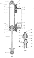
- Fig. 1 shows a damper device comprising a body 1, the upper top eye 2 of which is fixed to a part of a vehicle chassis 4 and the lower end eye 3 of which is fixed to a wheel mounting 5.
- the mounting on the chassis 4 and the wheel mounting 5 are shown only schematically in the drawing but more than one damper can naturally be used for each wheel, in conjunction with most suitable types of known wheel suspension arrangements, provided that there is sufficient space.
- This damper device is preferably used together with a spring element, such as a leaf spring or a coil spring.
- the coil spring is commonly placed around another supplementary shock absorber.
- the lower end eye 3 is fitted to a piston rod 6, which under relative movements between the chassis 4 and the wheel moves in and out of the damper body 1a. Also visible in Fig. 1 are the valve devices 7a, 7b, which are mounted in line, apart from one another at either end of a valve housing part 1b.
- Fig. 1a shows a plan view of the damper, in which the three parts of the body 1, the damper body 1 a, the valve housing 1b and the pressurization reservoir 1 c can be clearly seen.
- the three parts 1 a, 1b, 1 c are arranged in cavities connected by common walls, that is to say the body 1 is manufactured from a single part.
- the part is preferably a light-weight profile having good thermal conduction properties, such as an aluminum alloy, for example.
- the outer surface of the body 1 has alternating channels 8a and fins 8b. These channels 8a and fins 8b are preferably produced together with the internal through-cavities of the three parts 1a, 1b, 1c by extrusion of the basic part.
- the channels 8a/ the fins 8b help to provided a larger overall external area, which increases the cooling surface in contact with the surroundings, and the walls of the body 1 can be made thinner, whilst maintaining the strength and rigidity in certain directions.
- the body 1 is machined, for example so that the different parts 1a, 1b, 1c have different heights from one another, or take on a partially smooth outer surface. Threads and/or locking ring grooves can also be machined into the end parts of the through-cavities. Sealing parts can be fixed in these threads so that each cavity is defined in relation to the surroundings. See also Fig. 2 in which these sealing parts 18, 19a, 19b are shown more clearly. The part 18 therefore seals off the lower part of the damper body and the parts 19a, 19b define the interior of the pressurization reservoir 1 c in relation to the surroundings.
- the top eye 2 is also one such sealing part, which is firmly screwed into the damper body 1 a, as are also the valve devices 7a, 7b.
- Fig. 1b shows the damper from below, a view which exposes the end eye 3 and the return valve device 7b.
- the centered location of the compression valve device 7a in the valve housing 1 b is shown in Fig. 1 a.
- Fig. 2 shows the damper in cross section along the section line A-A.
- the damping chamber 1 a is divided into two damping chambers, a compression chamber C and a return chamber R, by a piston 9 which is mounted on the piston rod 6.
- the piston 9 moves so that the damping medium with which the damper device is filled is forced either through the piston valves, that is to say the gap that is created between the flexible shim washers 9a and the piston 9 or through ports 10a, 10b via the external, adjustable valve devices 7a, 7b out to the valve housing 1 b. From the valve housing 1b it returns to the damping chamber via the check valves 16.
- check valve refers to a valve which flows more in one direction. The difference in flow in the two directions is normally great, since the flow in one direction is often close to zero. In the main flow direction of the valve the pressure fall is usually significantly lower than in the valve system that generates the damping force. In certain cases, however, a pressure fall can be purposely built in, but it must be marginally lower than the set gas pressure in order to prevent cavitation.
- These check valves 16 ensure that the pressure in the damping chamber, whether it is the compression side C or the return side R, is always considerably high than the atmospheric pressure in the intended speed range of the damper.
- the pressure in the C/R low-pressure chamber would never be less than the pressure in the pressurization reservoir 1c.
- a certain proportion of the damping medium is also transported via a port 10c to/from the pressurization reservoir 1 c.
- the ports 10a, 10b connecting the internal volumes of the damping chamber 1a and valve housing 1b are arranged next to the two ends of the damping chamber, so that the damping medium has scope to flow into the internal volume of the valve housing 1b via the respective valve device 7a, 7b with the least possible loss of internal stroke.
- the internal volume of the valve housing 1b always has a pressure close to the pressure prevailing in the pressurization reservoir, since a further port 10c connects this volume to the internal volume of the pressurization reservoir 1c.
- the internal volume of the pressurization reservoir 1c may preferably be divided by a floating piston 11, which is acted upon by a pressure generated, for example, by a gas or a mechanical pressure member, such as a spring (not shown).
- the floating piston 11 can also be replaced by a pressurized rubber bladder or corresponding device for the pressurization of a medium.
- Fig. 3 shows an enlarged view of one of the valve devices 7a, 7b.
- the valve device 7a, 7b comprises an external high-speed adjustment device 13 and an external low-speed adjustment device 12.
- both of the valves comprise an adjustment which influences the pressure fall in the case of large flows (high-speed adjustment) 13 and an adjustment which influences the pressure fall mainly in the case of small flows (low-speed adjustment) 12, in such a way that the damping medium flows through a first adjustable restrictor 13a when the relative movement of the damper is high and through a second adjustable restrictor 12a when the relative speed is low.
- the low-speed restrictor 12a also has an effect on the high-speed restrictor, albeit to a small degree in percentage terms.
- the first adjustable restrictor 13a i.e. the high-speed adjustment, is adjusted via a screw device 13b, the position of which determines the relative distance between a spring holder 13c and a valve cone 13e.
- a spring 13d is arranged between the spring holder 13c and the valve cone 13e and the relative distance between the spring holder 13c and the valve cone 13e adjusts the force that is required in order to open the valve cone 13e, allowing the damping medium to pass through.
- the valve cone 13e bears against a valve seat 13f when it is closed.
- a check valve 16 opens as soon as the pressure inside the valve housing 1 b, which owing to the connecting port 10c is equal to the pressure in the pressure reservoir, has a pressure greater than in the respective C/R damping chamber.
- the other adjustable restrictor 12 i.e. the low-speed adjustment
- a valve 12b which functions as a needle valve in which the through-flow area 12a is determined by the position of the needle against the seat 12c.
- the seat 12c is arranged on a part of the high-speed adjustment device 13. Despite this, the setting of the respective valve is not changed by the adjustment. In addition, the compression damping can be adjusted without affecting the return damping and vice versa.
- valve seat 13f being the seat for the valve cone 13e on one side and the seat for the check valve 16 on the other, bears against a heel 17 turned in the inner surface of the valve housing.
- the damper device in Fig. 2 functions as follows.
- the pressure fall created over the piston 9 as a result of an externally acting force causes the damping medium to flow via the flow-restricting shims 9a and the valve device 7a, 7b to the other side of the piston 9.
- All valves generating a damping force, in both valve movement directions, comprising shim washers 9a on the main piston, an externally adjustable low-speed valve 12 and an externally adjustable high-speed valve 13, are connected in parallel, that is to say the flow resistance through the valves divides the flow of damping medium between the different valves.
- the damping medium that does not pass through the valve in the piston 9 flows into a space 14a, 14b between the valve cone 13e and a sealing part 15 forming a seal between the valve and the surroundings.
- the damping medium flows through the restrictor 12a and/or 13a on into the internal volume of the valve housing 1b.
- valve housing 1b Since the internal volume of the valve housing 1b is connected to the pressurized space in the pressurization reservoir 1 c via the port 10c, the same pressure prevails in both volumes. When this pressure is greater than the pressure in any of the C/R damping chambers, the check valve 16 is opened and pressurized damping medium flows into the C/R chamber where the lowest pressure prevails.
- valve devices 7a, 7b function in the same way, identical valves can be used for both the compression and the return stroke, but adjustment of the flows in both directions can be performed independently of one another.
Landscapes
- Engineering & Computer Science (AREA)
- General Engineering & Computer Science (AREA)
- Mechanical Engineering (AREA)
- Fluid-Damping Devices (AREA)
- Bridges Or Land Bridges (AREA)
Abstract
Description
- The invention relates to a damper device in the form of a shock absorber in which a piston acts in a damping medium in order to damp the movement between the wheels and chassis of a vehicle. The damper is intended for use under extreme ambient conditions including heat and dust, long strokes and high load stresses. The damper is extruded from a single body and comprises a damping chamber part, a valve housing part with adjustable valve devices and a pressurization reservoir, which pressurizes the damping medium in both the valve housing part and the damping chamber part. The three different parts are arranged parallel to one another and the internal volume of the valve housing is connected both to the pressurized interior of the pressurization reservoir and to both chambers of the damping chamber part, so that the damper always functions with a positive pressure in both the compression and the return chamber. The body has alternating, heat-conducting channels and fins on its outer surface. It is also pressurized on the low-pressure side of the piston, so that a positive pressure always prevails in the chamber when at minimum pressure. The flow resistance for the damping medium passing between the two damping chambers must be easily adjustable.
- Vehicles used under extreme ambient conditions such as difficult terrain, heat and dust, place heavy demands on the shock absorbers. In order to be able to absorb a large amount of damping energy efficiently, the shock absorber must have a long stroke. Owing to the high damping forces, the damper must be able to withstand high load stresses. It must also have a good cooling capacity in order to rapidly dissipate the damping energy that is converted into heat under the movements of the damper. High damping forces result in large pressure falls over the piston, which increase the risk of cavitation. In cavitation, gas bubbles are formed in the damping medium, which can lead to a reduction in the damping forces.
- Hitherto known dampers include
US 3,103,993 A1 , for example, which demonstrates a shock absorber with cooling flanges to increase the service life and to improve the functioning of the damper. The damper body comprises a single part with radial fins intended to increase the cooling area. Said damper body has four bored cavities, the first being the actual damping chamber, the second being used as a chamber for pressurizing the damper whilst handling the displacement generated by the piston rod and the temperature fluctuations caused by changes in volume, and the third and fourth chambers being adjustable ports that are used in order to carry the damping medium expelled by the solid piston from one damping chamber to the other. The damper described above lacks the facility for pressurizing the damping medium on both sides of the piston, which means that cavitation can easily occur when the damping medium flows through the flow-restricting third and fourth bores. -
US 5,178,239 shows a damper manufactured from an extruded cylinder body, in which the extrusion comprises holes that are used to lead the damping medium between the compression and return chambers when the damper is subjected to a high-speed stroke. The extruded fins also increase the heat exchange with the surroundings. The piston which divides off the damping chamber functions in a tube arranged inside the extruded cylinder body. On the return side of the piston the damper is pressurized by a gas-filled rubber bladder. The problem with this solution is that the damper is not externally adjustable but has a fixed damping characteristic which can only be modified by dismantling the damper and changing the flow-damping shims in the piston. Pressurization of the damper also occurs on only one side of the piston, which can lead to cavitation problems. - Another example is disclosed in
CA 565 074 A which corresponds to the preamble ofclaim 1 and describes a damping device which is manufactured from a single body. - The invention is defined by the technical features set forth in
claim 1 ; additional features of the invention are disclosed in the dependent product and method claims. - In order to obtain a compact, light and strong construction, the damper device is manufactured from a single part in which there are three throughholes extruded parallel to one another in the body of the damper device. These three holes may be of different dimensions and may be used as damper body, pressurization reservoir and valve housing. In order to create a large cooling area and a rigid construction, the extrusion also comprises axial cooling flanges in the outer part of the damper body.
- Since the three parts, the damper body, the pressurization reservoir and the valve housing are parallel to one another, connecting ports can easily be arranged between the internal spaces of the different parts. Placing valve devices at either end of the valve housing part and connecting the space between these to the pressurized space in the pressurization reservoir creates a damper which always functions with a positive pressure in both the compression and the return chamber. Because a positive pressure build-up prevails, cavitation can be avoided whilst the damping force characteristic in both stroke directions can be adjusted quite separately and independently of one another via the external adjustments.
- The valve devices are located concentrically apart at either end of the valve housing part. This location of the valve devices facilitates the transport of damping medium between the two damping chambers and allows an easy external adjustment of these. Valve devices of identical design can be used for compression and return damping.
- Locating the valve devices close to the compression and return chambers makes it possible to create large port areas, which means that the flow resistance of the damping medium to and from the valves is minimized.
- The valve devices comprise an external high-speed adjustment and an external low-speed adjustment. This means that one of these two adjustments influences the pressure fall under large flows (high piston rod speeds) and the other influences the pressure fall primarily under small flows (low piston rod speeds). The first adjustable restrictor, i.e. the high-speed adjustment, is adjusted by a screw device on which a spring holder is mounted, the position of the spring holder determining the spring tension on the valve cone. The other adjustable restrictor, i.e. the low-speed adjustment, is adjusted via a valve which functions as a needle valve in which the through-flow area is determined by the position of the needle. This restrictor is therefore entirely static.
- This valve construction in which the cone and the spring are located inside the valve seat simplifies the machining and affords lower product manufacturing costs. This is because the valve seat is relatively sunken and no machining of the valve is required inside the valve seat space.
- The invention will be described in more detail below, with reference to the drawings attached, in which:
-
Fig. 1 shows the damper schematically, clamped in a vehicle. -
Fig. 1a shows a plan view of the damper. -
Fig. 1b shows a view of the damper from below. -
Fig. 2 shows the damper in cross section along the section line A-A. -
Fig. 3 shows a detailed view of one of the valves. -
Fig. 1 shows a damper device comprising abody 1, the uppertop eye 2 of which is fixed to a part of avehicle chassis 4 and thelower end eye 3 of which is fixed to awheel mounting 5. The mounting on thechassis 4 and thewheel mounting 5 are shown only schematically in the drawing but more than one damper can naturally be used for each wheel, in conjunction with most suitable types of known wheel suspension arrangements, provided that there is sufficient space. This damper device is preferably used together with a spring element, such as a leaf spring or a coil spring. The coil spring is commonly placed around another supplementary shock absorber. - The
lower end eye 3 is fitted to apiston rod 6, which under relative movements between thechassis 4 and the wheel moves in and out of thedamper body 1a. Also visible inFig. 1 are thevalve devices valve housing part 1b. -
Fig. 1a shows a plan view of the damper, in which the three parts of thebody 1, thedamper body 1 a, thevalve housing 1b and thepressurization reservoir 1 c can be clearly seen. The threeparts body 1 is manufactured from a single part. The part is preferably a light-weight profile having good thermal conduction properties, such as an aluminum alloy, for example. The outer surface of thebody 1 has alternatingchannels 8a andfins 8b. Thesechannels 8a andfins 8b are preferably produced together with the internal through-cavities of the threeparts - The
channels 8a/ thefins 8b help to provided a larger overall external area, which increases the cooling surface in contact with the surroundings, and the walls of thebody 1 can be made thinner, whilst maintaining the strength and rigidity in certain directions. - After extrusion, the
body 1 is machined, for example so that thedifferent parts Fig. 2 in which these sealingparts part 18 therefore seals off the lower part of the damper body and theparts pressurization reservoir 1 c in relation to the surroundings. Thetop eye 2 is also one such sealing part, which is firmly screwed into thedamper body 1 a, as are also thevalve devices -
Fig. 1b shows the damper from below, a view which exposes theend eye 3 and thereturn valve device 7b. The centered location of thecompression valve device 7a in thevalve housing 1 b is shown inFig. 1 a. -
Fig. 2 shows the damper in cross section along the section line A-A. The dampingchamber 1 a is divided into two damping chambers, a compression chamber C and a return chamber R, by apiston 9 which is mounted on thepiston rod 6. Under the piston rod movements, thepiston 9 moves so that the damping medium with which the damper device is filled is forced either through the piston valves, that is to say the gap that is created between theflexible shim washers 9a and thepiston 9 or throughports adjustable valve devices valve housing 1 b. From thevalve housing 1b it returns to the damping chamber via thecheck valves 16. - The term check valve here refers to a valve which flows more in one direction. The difference in flow in the two directions is normally great, since the flow in one direction is often close to zero. In the main flow direction of the valve the pressure fall is usually significantly lower than in the valve system that generates the damping force. In certain cases, however, a pressure fall can be purposely built in, but it must be marginally lower than the set gas pressure in order to prevent cavitation. These
check valves 16 ensure that the pressure in the damping chamber, whether it is the compression side C or the return side R, is always considerably high than the atmospheric pressure in the intended speed range of the damper. When the pressure in the C/R damping chamber in which the lowest pressure prevails drops to the pressure prevailing inpressurization reservoir 1 c, thecheck valve 16 coupled to this C/R chamber opens and pressurized damping medium is led into this chamber. The pressure in the low-pressure C/R chamber, the damping chamber which for the moment has the lowest pressure, is therefore always positive and is well above the atmospheric pressure, so that cavitation can therefore be avoided. - Were it not for the pressure fall that occurs in the ports and check valves, the pressure in the C/R low-pressure chamber would never be less than the pressure in the
pressurization reservoir 1c. As a result of the changes in volume caused by the piston rod displacement, a certain proportion of the damping medium is also transported via aport 10c to/from thepressurization reservoir 1 c. Theports chamber 1a andvalve housing 1b are arranged next to the two ends of the damping chamber, so that the damping medium has scope to flow into the internal volume of thevalve housing 1b via therespective valve device - The internal volume of the
valve housing 1b always has a pressure close to the pressure prevailing in the pressurization reservoir, since afurther port 10c connects this volume to the internal volume of thepressurization reservoir 1c. - The internal volume of the
pressurization reservoir 1c may preferably be divided by a floatingpiston 11, which is acted upon by a pressure generated, for example, by a gas or a mechanical pressure member, such as a spring (not shown). The floatingpiston 11 can also be replaced by a pressurized rubber bladder or corresponding device for the pressurization of a medium. -
Fig. 3 shows an enlarged view of one of thevalve devices valve device speed adjustment device 13 and an external low-speed adjustment device 12. This means that thevalve devices adjustable restrictor 13a when the relative movement of the damper is high and through a secondadjustable restrictor 12a when the relative speed is low. The low-speed restrictor 12a also has an effect on the high-speed restrictor, albeit to a small degree in percentage terms. The firstadjustable restrictor 13a, i.e. the high-speed adjustment, is adjusted via ascrew device 13b, the position of which determines the relative distance between aspring holder 13c and avalve cone 13e. Aspring 13d is arranged between thespring holder 13c and thevalve cone 13e and the relative distance between thespring holder 13c and thevalve cone 13e adjusts the force that is required in order to open thevalve cone 13e, allowing the damping medium to pass through. Thevalve cone 13e bears against avalve seat 13f when it is closed. Acheck valve 16 opens as soon as the pressure inside thevalve housing 1 b, which owing to the connectingport 10c is equal to the pressure in the pressure reservoir, has a pressure greater than in the respective C/R damping chamber. The otheradjustable restrictor 12, i.e. the low-speed adjustment, is adjusted via avalve 12b which functions as a needle valve in which the through-flow area 12a is determined by the position of the needle against theseat 12c. Theseat 12c is arranged on a part of the high-speed adjustment device 13. Despite this, the setting of the respective valve is not changed by the adjustment. In addition, the compression damping can be adjusted without affecting the return damping and vice versa. - The
valve seat 13f, being the seat for thevalve cone 13e on one side and the seat for thecheck valve 16 on the other, bears against aheel 17 turned in the inner surface of the valve housing. The fact that thespring 13d is arranged in the internal volume of the valve housing inside the valve seat, rather than on top of the valve seat, as in previously known valves, means that this machining of theheel 17 can be carried out with a shorter tool protrusion than hitherto. This valve design construction therefore simplifies the machining, making the product cheaper to manufacture. - The damper device in
Fig. 2 functions as follows. The pressure fall created over thepiston 9 as a result of an externally acting force causes the damping medium to flow via the flow-restrictingshims 9a and thevalve device piston 9. All valves generating a damping force, in both valve movement directions, comprisingshim washers 9a on the main piston, an externally adjustable low-speed valve 12 and an externally adjustable high-speed valve 13, are connected in parallel, that is to say the flow resistance through the valves divides the flow of damping medium between the different valves. The damping medium that does not pass through the valve in thepiston 9 flows into aspace valve cone 13e and a sealingpart 15 forming a seal between the valve and the surroundings. Depending on the rate of flow and the adjustment setting, the damping medium flows through the restrictor 12a and/or 13a on into the internal volume of thevalve housing 1b. - Since the internal volume of the
valve housing 1b is connected to the pressurized space in thepressurization reservoir 1 c via theport 10c, the same pressure prevails in both volumes. When this pressure is greater than the pressure in any of the C/R damping chambers, thecheck valve 16 is opened and pressurized damping medium flows into the C/R chamber where the lowest pressure prevails. - Since both of the
valve devices
Claims (12)
- A damper device (1) for damping movement between wheel and chassis of a vehicle, said damper device being arranged to be filled with a damping medium in which the device is manufactured from a single body (1) and comprises a damping chamber part (1a), the internal volume of which is divided into a compression chamber (C) and a return chamber (R) by a piston (9) fixed to a piston rod (6), a valve housing part (1b) with valve devices (7a, 7b) arranged at either end of the valve housing part (1b) and a pressurization reservoir (1c), the internal volume of which is divided off by a member (11), which is acted upon by a pressure which pressurizes the damping medium in the device (1), wherein the three different parts (1a, 1b, 1c) are arranged parallel to one another and the internal volume of the valve housing (1b) is connected both to the pressurized interior of the pressurization reservoir (1c) and, via the valve devices (7a, 7b), to both chambers (C, R) of the damping chamber part (1a), characterized in that the valve devices (7a, 7b) are adjustable, and in that the valve devices (7a, 7b) are so designed that both of the valves comprise an adjustment which influences the pressure fall in the case of large flows (13) and an adjustment which influences the pressure fall mainly in the case of small flows (12).
- The damper device (1) as claimed in claim 1, characterized in that the outer surface of the body (1) has alternating channels (8a) and fins (8b) or corresponding longitudinal structures which increase the surface of the damper device (1) exposed to the surroundings.
- The damper device as claimed in claim 1 or 2, characterized in that the valve devices (7a, 7b) comprise an external high-speed adjustment device (13) and an external low-speed adjustment device (12).
- The damper device as claimed in any of the preceding claims characterized in that the valve devices (7a, 7b) comprise a first adjustable restrictor (13a) and a second adjustable restrictor (12a) for adjusting the flow at high and low damping speeds respectively.
- The damper device as claimed in any one of the preceding claims, characterized in that a check valve (16), which bears against a valve seat (13f), opens and connects the interior of The valve housing (1b) to the (C/R) damping chamber as soon as the pressure inside the valve housing (1b) is greater than in the respective (C/R) damping chamber.
- The damper device as claimed in claim 4 or 5, characterized in that the first adjustable restrictor (13a), i.e. the high-speed adjustment, is adjusted via a screw device (13b), the position of which determines the relative distance between a spring holder (13c) and a valve cone (13e), a spring (13d) being arranged between the spring holder (13c) and the valve cone (13e) and the relative distance between the spring holder (13c) and valve cone (13e) adjusting the force that is required in order to open the valve cone (13e) and allowing the damping medium to pass.
- The damper device as claimed in claim 4, 5 or 6, characterized in that that the second adjustable restrictor (12), i.e. the low-speed adjustment, which also to a certain extent has an effect on the restrictor for high piston rod speeds, is adjusted via a valve (12b) which functions as a needle valve in which the through-flow area (12a) is determined by the position of the needle against the seat (12c).
- The damper device as claimed in any one of the preceding claims, characterized in that the valve seat (13f) bears against a heel (17) turned in the inner surface of the valve housing (b).
- Manufacture of a damper device (1) as claimed in any one of the preceding claims, wherein the three parts of the device, the damping chamber (1a), the valve housing (1b) and the pressurization reservoir (1c), are arranged in through-cavities extruded from a single part and arranged parallel to one another in this part, characterized in that after extrusion, ports (10a, 10b, 10c) are made between the cavities containing the damping chamber (1 a) and the valve housing (1b) and between the valve housing (1b) and the pressurization reservoir (1c).
- The manufacture of a damper device as claimed in claim 9, characterized in that both the three cavities adapted to the parts (1 a, 1b, 1 c) and alternating channels (8a) and fins (8b) or corresponding longitudinal structures in the outer surface of the damper device (1) are produced in one and the same step in the extrusion process.
- The manufacture of a damper device as claimed in claim 9 or 10, characterized in that threads and/or locking ring grooves are machined into the end parts of the through-cavities, in which sealing parts (2, 7a, 7b, 18, 19a, 19) are fixed so that each cavity is defined in relation to the surroundings.
- The manufacture of a damper device as claimed in claim 11, characterized in that the cavity designed to be used as valve housing (1b) is sealed at both ends of the valve devices (7a, 7b)
Applications Claiming Priority (2)
| Application Number | Priority Date | Filing Date | Title |
|---|---|---|---|
| SE0600629A SE531628C2 (en) | 2006-03-20 | 2006-03-20 | Attenuator device and manufacture of such attenuator device |
| PCT/SE2007/000262 WO2007108747A1 (en) | 2006-03-20 | 2007-03-16 | Damper device and manufacture of such a damper device |
Publications (2)
| Publication Number | Publication Date |
|---|---|
| EP1996830A1 EP1996830A1 (en) | 2008-12-03 |
| EP1996830B1 true EP1996830B1 (en) | 2011-07-27 |
Family
ID=38522710
Family Applications (1)
| Application Number | Title | Priority Date | Filing Date |
|---|---|---|---|
| EP07716073A Active EP1996830B1 (en) | 2006-03-20 | 2007-03-16 | Damper device and manufacture of such a damper device |
Country Status (5)
| Country | Link |
|---|---|
| US (1) | US20090314592A1 (en) |
| EP (1) | EP1996830B1 (en) |
| AT (1) | ATE518074T1 (en) |
| SE (1) | SE531628C2 (en) |
| WO (1) | WO2007108747A1 (en) |
Families Citing this family (32)
| Publication number | Priority date | Publication date | Assignee | Title |
|---|---|---|---|---|
| WO2009073810A2 (en) * | 2007-12-05 | 2009-06-11 | Pacific Scientific Company | Snubber valve |
| US9452654B2 (en) | 2009-01-07 | 2016-09-27 | Fox Factory, Inc. | Method and apparatus for an adjustable damper |
| US10047817B2 (en) | 2009-01-07 | 2018-08-14 | Fox Factory, Inc. | Method and apparatus for an adjustable damper |
| US10060499B2 (en) | 2009-01-07 | 2018-08-28 | Fox Factory, Inc. | Method and apparatus for an adjustable damper |
| US20100170760A1 (en) * | 2009-01-07 | 2010-07-08 | John Marking | Remotely Operated Bypass for a Suspension Damper |
| US8627932B2 (en) | 2009-01-07 | 2014-01-14 | Fox Factory, Inc. | Bypass for a suspension damper |
| US11306798B2 (en) | 2008-05-09 | 2022-04-19 | Fox Factory, Inc. | Position sensitive suspension damping with an active valve |
| DE102009020951B4 (en) * | 2008-05-28 | 2012-07-12 | Stabilus Gmbh | Infinitely lockable locking device |
| US8393446B2 (en) | 2008-08-25 | 2013-03-12 | David M Haugen | Methods and apparatus for suspension lock out and signal generation |
| US9140325B2 (en) | 2009-03-19 | 2015-09-22 | Fox Factory, Inc. | Methods and apparatus for selective spring pre-load adjustment |
| US10036443B2 (en) | 2009-03-19 | 2018-07-31 | Fox Factory, Inc. | Methods and apparatus for suspension adjustment |
| US9422018B2 (en) | 2008-11-25 | 2016-08-23 | Fox Factory, Inc. | Seat post |
| US12491961B2 (en) | 2008-11-25 | 2025-12-09 | Fox Factory, Inc. | Seat post |
| US9038791B2 (en) | 2009-01-07 | 2015-05-26 | Fox Factory, Inc. | Compression isolator for a suspension damper |
| US11299233B2 (en) | 2009-01-07 | 2022-04-12 | Fox Factory, Inc. | Method and apparatus for an adjustable damper |
| US12122205B2 (en) | 2009-01-07 | 2024-10-22 | Fox Factory, Inc. | Active valve for an internal bypass |
| US8955653B2 (en) | 2009-10-13 | 2015-02-17 | Fox Factory, Incorporated | Methods and apparatus for controlling a fluid damper |
| US8672106B2 (en) | 2009-10-13 | 2014-03-18 | Fox Factory, Inc. | Self-regulating suspension |
| US8763770B2 (en) * | 2011-03-03 | 2014-07-01 | Fox Factory, Inc. | Cooler for a suspension damper |
| US10697514B2 (en) | 2010-01-20 | 2020-06-30 | Fox Factory, Inc. | Remotely operated bypass for a suspension damper |
| CN102146977A (en) * | 2011-03-29 | 2011-08-10 | 重庆小康汽车集团有限公司 | Vacuum assembly system for airbag vibration damper and assembly method thereof |
| EP3567272B1 (en) | 2011-09-12 | 2021-05-26 | Fox Factory, Inc. | Methods and apparatus for suspension set up |
| US11279199B2 (en) | 2012-01-25 | 2022-03-22 | Fox Factory, Inc. | Suspension damper with by-pass valves |
| US10330171B2 (en) | 2012-05-10 | 2019-06-25 | Fox Factory, Inc. | Method and apparatus for an adjustable damper |
| JP6121888B2 (en) * | 2013-09-27 | 2017-04-26 | 株式会社ショーワ | Suspension device and suspension system |
| US9168972B2 (en) * | 2014-01-02 | 2015-10-27 | Taiwan Hodaka Industrial Co., Ltd. | Control device for the rear shock absorber of a bicycle |
| US9470285B2 (en) | 2014-04-08 | 2016-10-18 | The Boeing Company | Aircraft door dampening system |
| JP6417281B2 (en) * | 2015-06-10 | 2018-11-07 | Kyb株式会社 | Shock absorber |
| US10737546B2 (en) | 2016-04-08 | 2020-08-11 | Fox Factory, Inc. | Electronic compression and rebound control |
| US11434968B2 (en) * | 2019-02-25 | 2022-09-06 | Mark Brendan Newhan | Vehicle shock absorber |
| CN121420143A (en) * | 2023-07-13 | 2026-01-27 | 多媒体股份有限公司 | Position-selectable damper |
| US20250257783A1 (en) * | 2024-02-08 | 2025-08-14 | Fundamental Motorsports, Llc | Shock body having raised cooling pattern on an exterior of a cylinder |
Family Cites Families (12)
| Publication number | Priority date | Publication date | Assignee | Title |
|---|---|---|---|---|
| CA565074A (en) | 1958-10-21 | Houdaille Industries | Reciprocating piston type hydraulic damper | |
| US1492328A (en) * | 1921-09-24 | 1924-04-29 | James S Lang | Shock absorber |
| US2122407A (en) * | 1937-03-15 | 1938-07-05 | Houde Eng Corp | Hydraulic shock absorber |
| US3103993A (en) * | 1959-12-09 | 1963-09-17 | Houdaille Industries Inc | Linear hydraulic damper |
| JPS4837572A (en) * | 1971-09-17 | 1973-06-02 | ||
| DE3816821A1 (en) * | 1988-05-18 | 1989-11-23 | Lisega Kraftwerktech Gmbh | HYDRAULIC SHOCK BRAKE |
| US5096026A (en) * | 1990-09-17 | 1992-03-17 | Gilles Vautour | Double-acting hydraulic piston |
| US5178239A (en) * | 1991-01-15 | 1993-01-12 | Ride On, Inc. | Shock absorber |
| US6142497A (en) * | 1997-09-09 | 2000-11-07 | Baldomero; Ricardo R. | Temperature heat sink for damping cartridge |
| US20040090020A1 (en) * | 2002-11-08 | 2004-05-13 | Arctic Cat, Inc. | Electronically controlled active suspension damper |
| US6892865B2 (en) * | 2003-08-01 | 2005-05-17 | Arvin Technologies, Inc. | Monotube shock absorber remote reservoir fluid connection |
| US7628259B2 (en) * | 2004-11-08 | 2009-12-08 | Thyssenkrupp Bilstein Of America, Inc. | Fluid flow regulation of a vehicle shock absorber/damper |
-
2006
- 2006-03-20 SE SE0600629A patent/SE531628C2/en unknown
-
2007
- 2007-03-16 AT AT07716073T patent/ATE518074T1/en not_active IP Right Cessation
- 2007-03-16 WO PCT/SE2007/000262 patent/WO2007108747A1/en not_active Ceased
- 2007-03-16 US US12/293,473 patent/US20090314592A1/en not_active Abandoned
- 2007-03-16 EP EP07716073A patent/EP1996830B1/en active Active
Also Published As
| Publication number | Publication date |
|---|---|
| EP1996830A1 (en) | 2008-12-03 |
| WO2007108747A1 (en) | 2007-09-27 |
| US20090314592A1 (en) | 2009-12-24 |
| SE531628C2 (en) | 2009-06-09 |
| SE0600629L (en) | 2007-09-21 |
| ATE518074T1 (en) | 2011-08-15 |
Similar Documents
| Publication | Publication Date | Title |
|---|---|---|
| EP1996830B1 (en) | Damper device and manufacture of such a damper device | |
| EP1685480B1 (en) | Shock absorber assembly | |
| US7628259B2 (en) | Fluid flow regulation of a vehicle shock absorber/damper | |
| US7325660B2 (en) | Fluid flow regulation of a vehicle shock absorber/damper | |
| EP2156069B1 (en) | Pressure reservoir for shock absorber | |
| US9091319B2 (en) | Shock absorber with hydraulic flow ducts | |
| EP1659310B1 (en) | Damper (shock absorber) intended for vehicles | |
| EP1937995B1 (en) | Arrangement for telescopic fork leg with parallel damping | |
| US9371882B2 (en) | Shock absorber | |
| US7191877B2 (en) | Fluid flow regulation of a vehicle shock absorber/damper | |
| US11345431B2 (en) | Pressurized telescopic front fork leg, front fork and vehicle | |
| EP1203712A2 (en) | Linked suspension system for a vehicle | |
| US6296235B1 (en) | Automobile stabilization assembly | |
| US20090115159A1 (en) | Arrangement for telescopic fork leg with parallel damping | |
| US20160298713A1 (en) | Shock absorber | |
| JP2006514728A (en) | Controllable piston valve and / or bottom valve for shock absorber | |
| EP1190184B1 (en) | Automotive self-adjustable damper with a self-correcting dissipation characteristic | |
| AU2004262730B2 (en) | Shock absorber assembly | |
| JPH03272339A (en) | Hydraulic shock absorber | |
| JPH0366938A (en) | strut device | |
| JP2006132593A (en) | Hydraulic shock absorber for vehicles |
Legal Events
| Date | Code | Title | Description |
|---|---|---|---|
| PUAI | Public reference made under article 153(3) epc to a published international application that has entered the european phase |
Free format text: ORIGINAL CODE: 0009012 |
|
| 17P | Request for examination filed |
Effective date: 20080909 |
|
| AK | Designated contracting states |
Kind code of ref document: A1 Designated state(s): AT BE BG CH CY CZ DE DK EE ES FI FR GB GR HU IE IS IT LI LT LU LV MC MT NL PL PT RO SE SI SK TR |
|
| 17Q | First examination report despatched |
Effective date: 20100210 |
|
| GRAP | Despatch of communication of intention to grant a patent |
Free format text: ORIGINAL CODE: EPIDOSNIGR1 |
|
| DAX | Request for extension of the european patent (deleted) | ||
| GRAS | Grant fee paid |
Free format text: ORIGINAL CODE: EPIDOSNIGR3 |
|
| GRAA | (expected) grant |
Free format text: ORIGINAL CODE: 0009210 |
|
| AK | Designated contracting states |
Kind code of ref document: B1 Designated state(s): AT BE BG CH CY CZ DE DK EE ES FI FR GB GR HU IE IS IT LI LT LU LV MC MT NL PL PT RO SE SI SK TR |
|
| REG | Reference to a national code |
Ref country code: GB Ref legal event code: FG4D |
|
| REG | Reference to a national code |
Ref country code: CH Ref legal event code: EP |
|
| REG | Reference to a national code |
Ref country code: DE Ref legal event code: R096 Ref document number: 602007016076 Country of ref document: DE Effective date: 20110922 |
|
| REG | Reference to a national code |
Ref country code: NL Ref legal event code: VDEP Effective date: 20110727 |
|
| REG | Reference to a national code |
Ref country code: AT Ref legal event code: MK05 Ref document number: 518074 Country of ref document: AT Kind code of ref document: T Effective date: 20110727 |
|
| PG25 | Lapsed in a contracting state [announced via postgrant information from national office to epo] |
Ref country code: PT Free format text: LAPSE BECAUSE OF FAILURE TO SUBMIT A TRANSLATION OF THE DESCRIPTION OR TO PAY THE FEE WITHIN THE PRESCRIBED TIME-LIMIT Effective date: 20111128 Ref country code: FI Free format text: LAPSE BECAUSE OF FAILURE TO SUBMIT A TRANSLATION OF THE DESCRIPTION OR TO PAY THE FEE WITHIN THE PRESCRIBED TIME-LIMIT Effective date: 20110727 Ref country code: IS Free format text: LAPSE BECAUSE OF FAILURE TO SUBMIT A TRANSLATION OF THE DESCRIPTION OR TO PAY THE FEE WITHIN THE PRESCRIBED TIME-LIMIT Effective date: 20111127 Ref country code: BE Free format text: LAPSE BECAUSE OF FAILURE TO SUBMIT A TRANSLATION OF THE DESCRIPTION OR TO PAY THE FEE WITHIN THE PRESCRIBED TIME-LIMIT Effective date: 20110727 Ref country code: LT Free format text: LAPSE BECAUSE OF FAILURE TO SUBMIT A TRANSLATION OF THE DESCRIPTION OR TO PAY THE FEE WITHIN THE PRESCRIBED TIME-LIMIT Effective date: 20110727 Ref country code: SE Free format text: LAPSE BECAUSE OF FAILURE TO SUBMIT A TRANSLATION OF THE DESCRIPTION OR TO PAY THE FEE WITHIN THE PRESCRIBED TIME-LIMIT Effective date: 20110727 Ref country code: NL Free format text: LAPSE BECAUSE OF FAILURE TO SUBMIT A TRANSLATION OF THE DESCRIPTION OR TO PAY THE FEE WITHIN THE PRESCRIBED TIME-LIMIT Effective date: 20110727 |
|
| PG25 | Lapsed in a contracting state [announced via postgrant information from national office to epo] |
Ref country code: AT Free format text: LAPSE BECAUSE OF FAILURE TO SUBMIT A TRANSLATION OF THE DESCRIPTION OR TO PAY THE FEE WITHIN THE PRESCRIBED TIME-LIMIT Effective date: 20110727 Ref country code: LV Free format text: LAPSE BECAUSE OF FAILURE TO SUBMIT A TRANSLATION OF THE DESCRIPTION OR TO PAY THE FEE WITHIN THE PRESCRIBED TIME-LIMIT Effective date: 20110727 Ref country code: CY Free format text: LAPSE BECAUSE OF FAILURE TO SUBMIT A TRANSLATION OF THE DESCRIPTION OR TO PAY THE FEE WITHIN THE PRESCRIBED TIME-LIMIT Effective date: 20110727 Ref country code: GR Free format text: LAPSE BECAUSE OF FAILURE TO SUBMIT A TRANSLATION OF THE DESCRIPTION OR TO PAY THE FEE WITHIN THE PRESCRIBED TIME-LIMIT Effective date: 20111028 Ref country code: SI Free format text: LAPSE BECAUSE OF FAILURE TO SUBMIT A TRANSLATION OF THE DESCRIPTION OR TO PAY THE FEE WITHIN THE PRESCRIBED TIME-LIMIT Effective date: 20110727 Ref country code: PL Free format text: LAPSE BECAUSE OF FAILURE TO SUBMIT A TRANSLATION OF THE DESCRIPTION OR TO PAY THE FEE WITHIN THE PRESCRIBED TIME-LIMIT Effective date: 20110727 |
|
| PG25 | Lapsed in a contracting state [announced via postgrant information from national office to epo] |
Ref country code: CZ Free format text: LAPSE BECAUSE OF FAILURE TO SUBMIT A TRANSLATION OF THE DESCRIPTION OR TO PAY THE FEE WITHIN THE PRESCRIBED TIME-LIMIT Effective date: 20110727 Ref country code: SK Free format text: LAPSE BECAUSE OF FAILURE TO SUBMIT A TRANSLATION OF THE DESCRIPTION OR TO PAY THE FEE WITHIN THE PRESCRIBED TIME-LIMIT Effective date: 20110727 |
|
| PG25 | Lapsed in a contracting state [announced via postgrant information from national office to epo] |
Ref country code: RO Free format text: LAPSE BECAUSE OF FAILURE TO SUBMIT A TRANSLATION OF THE DESCRIPTION OR TO PAY THE FEE WITHIN THE PRESCRIBED TIME-LIMIT Effective date: 20110727 Ref country code: EE Free format text: LAPSE BECAUSE OF FAILURE TO SUBMIT A TRANSLATION OF THE DESCRIPTION OR TO PAY THE FEE WITHIN THE PRESCRIBED TIME-LIMIT Effective date: 20110727 |
|
| PLBE | No opposition filed within time limit |
Free format text: ORIGINAL CODE: 0009261 |
|
| STAA | Information on the status of an ep patent application or granted ep patent |
Free format text: STATUS: NO OPPOSITION FILED WITHIN TIME LIMIT |
|
| PG25 | Lapsed in a contracting state [announced via postgrant information from national office to epo] |
Ref country code: DK Free format text: LAPSE BECAUSE OF FAILURE TO SUBMIT A TRANSLATION OF THE DESCRIPTION OR TO PAY THE FEE WITHIN THE PRESCRIBED TIME-LIMIT Effective date: 20110727 |
|
| 26N | No opposition filed |
Effective date: 20120502 |
|
| REG | Reference to a national code |
Ref country code: DE Ref legal event code: R097 Ref document number: 602007016076 Country of ref document: DE Effective date: 20120502 |
|
| PG25 | Lapsed in a contracting state [announced via postgrant information from national office to epo] |
Ref country code: MC Free format text: LAPSE BECAUSE OF NON-PAYMENT OF DUE FEES Effective date: 20120331 |
|
| REG | Reference to a national code |
Ref country code: CH Ref legal event code: PL |
|
| REG | Reference to a national code |
Ref country code: IE Ref legal event code: MM4A |
|
| PG25 | Lapsed in a contracting state [announced via postgrant information from national office to epo] |
Ref country code: IE Free format text: LAPSE BECAUSE OF NON-PAYMENT OF DUE FEES Effective date: 20120316 Ref country code: LI Free format text: LAPSE BECAUSE OF NON-PAYMENT OF DUE FEES Effective date: 20120331 Ref country code: CH Free format text: LAPSE BECAUSE OF NON-PAYMENT OF DUE FEES Effective date: 20120331 |
|
| PG25 | Lapsed in a contracting state [announced via postgrant information from national office to epo] |
Ref country code: ES Free format text: LAPSE BECAUSE OF FAILURE TO SUBMIT A TRANSLATION OF THE DESCRIPTION OR TO PAY THE FEE WITHIN THE PRESCRIBED TIME-LIMIT Effective date: 20111107 |
|
| PG25 | Lapsed in a contracting state [announced via postgrant information from national office to epo] |
Ref country code: BG Free format text: LAPSE BECAUSE OF FAILURE TO SUBMIT A TRANSLATION OF THE DESCRIPTION OR TO PAY THE FEE WITHIN THE PRESCRIBED TIME-LIMIT Effective date: 20111027 |
|
| PG25 | Lapsed in a contracting state [announced via postgrant information from national office to epo] |
Ref country code: MT Free format text: LAPSE BECAUSE OF FAILURE TO SUBMIT A TRANSLATION OF THE DESCRIPTION OR TO PAY THE FEE WITHIN THE PRESCRIBED TIME-LIMIT Effective date: 20110727 |
|
| PG25 | Lapsed in a contracting state [announced via postgrant information from national office to epo] |
Ref country code: TR Free format text: LAPSE BECAUSE OF FAILURE TO SUBMIT A TRANSLATION OF THE DESCRIPTION OR TO PAY THE FEE WITHIN THE PRESCRIBED TIME-LIMIT Effective date: 20110727 |
|
| PG25 | Lapsed in a contracting state [announced via postgrant information from national office to epo] |
Ref country code: LU Free format text: LAPSE BECAUSE OF NON-PAYMENT OF DUE FEES Effective date: 20120316 |
|
| PG25 | Lapsed in a contracting state [announced via postgrant information from national office to epo] |
Ref country code: HU Free format text: LAPSE BECAUSE OF FAILURE TO SUBMIT A TRANSLATION OF THE DESCRIPTION OR TO PAY THE FEE WITHIN THE PRESCRIBED TIME-LIMIT Effective date: 20070316 |
|
| REG | Reference to a national code |
Ref country code: FR Ref legal event code: PLFP Year of fee payment: 10 |
|
| REG | Reference to a national code |
Ref country code: FR Ref legal event code: PLFP Year of fee payment: 11 |
|
| REG | Reference to a national code |
Ref country code: FR Ref legal event code: PLFP Year of fee payment: 12 |
|
| P01 | Opt-out of the competence of the unified patent court (upc) registered |
Effective date: 20230528 |
|
| PGFP | Annual fee paid to national office [announced via postgrant information from national office to epo] |
Ref country code: DE Payment date: 20250325 Year of fee payment: 19 |
|
| PGFP | Annual fee paid to national office [announced via postgrant information from national office to epo] |
Ref country code: FR Payment date: 20250225 Year of fee payment: 19 |
|
| PGFP | Annual fee paid to national office [announced via postgrant information from national office to epo] |
Ref country code: IT Payment date: 20250221 Year of fee payment: 19 Ref country code: GB Payment date: 20250319 Year of fee payment: 19 |