EP1996089B1 - Medical grasping device - Google Patents
Medical grasping device Download PDFInfo
- Publication number
- EP1996089B1 EP1996089B1 EP07753512.8A EP07753512A EP1996089B1 EP 1996089 B1 EP1996089 B1 EP 1996089B1 EP 07753512 A EP07753512 A EP 07753512A EP 1996089 B1 EP1996089 B1 EP 1996089B1
- Authority
- EP
- European Patent Office
- Prior art keywords
- control member
- grasping
- grasping device
- wire
- loops
- Prior art date
- Legal status (The legal status is an assumption and is not a legal conclusion. Google has not performed a legal analysis and makes no representation as to the accuracy of the status listed.)
- Active
Links
Images


Classifications
-
- A—HUMAN NECESSITIES
- A61—MEDICAL OR VETERINARY SCIENCE; HYGIENE
- A61B—DIAGNOSIS; SURGERY; IDENTIFICATION
- A61B17/00—Surgical instruments, devices or methods
- A61B17/22—Implements for squeezing-off ulcers or the like on inner organs of the body; Implements for scraping-out cavities of body organs, e.g. bones; for invasive removal or destruction of calculus using mechanical vibrations; for removing obstructions in blood vessels, not otherwise provided for
- A61B17/221—Gripping devices in the form of loops or baskets for gripping calculi or similar types of obstructions
-
- A—HUMAN NECESSITIES
- A61—MEDICAL OR VETERINARY SCIENCE; HYGIENE
- A61B—DIAGNOSIS; SURGERY; IDENTIFICATION
- A61B17/00—Surgical instruments, devices or methods
- A61B2017/00831—Material properties
- A61B2017/00867—Material properties shape memory effect
-
- A—HUMAN NECESSITIES
- A61—MEDICAL OR VETERINARY SCIENCE; HYGIENE
- A61B—DIAGNOSIS; SURGERY; IDENTIFICATION
- A61B17/00—Surgical instruments, devices or methods
- A61B17/22—Implements for squeezing-off ulcers or the like on inner organs of the body; Implements for scraping-out cavities of body organs, e.g. bones; for invasive removal or destruction of calculus using mechanical vibrations; for removing obstructions in blood vessels, not otherwise provided for
- A61B17/221—Gripping devices in the form of loops or baskets for gripping calculi or similar types of obstructions
- A61B2017/2215—Gripping devices in the form of loops or baskets for gripping calculi or similar types of obstructions having an open distal end
Definitions
- This invention is related to medical devices and in particular to a medical grasping device.
- Certain medical devices are known that are utilized in the ducts and vessels of a human or veterinary patient for retrieval of bodies from the patient.
- retrieval devices are known for removing calculi such as kidney stones or gallstones from a patient, where the retrieval device is delivered to the target site via the urethra or biliary duct, respectively.
- the device's distal tip is adapted to deploy at the site to form a basket shape to trap the calculi after which the basket is collapsed to grasp the calculi. Both the device and the grasped calculi are then withdrawn from the patient.
- a bifurcated stent graft at the site of an abdominal aortic aneurysm, when surgical access has been obtained through the femoral arteries on both sides of the groin, it is desirable to grasp the distal tip of a guide wire extending into the aneurysm from the contralateral iliac artery, to be pulled into the ipsilateral iliac artery at the vessel's aorto-iliac bifurcation, for eventual placement of the contralateral leg extension of the stent graft.
- a suture loop on a catheter distal tip For vascular use, another known device is a suture loop on a catheter distal tip. Yet another is a guide wire that has been doubled over and extended through a catheter so that its distal end forms into a loop that extends axially from the catheter's distal end to be utilized as a retriever when it is pulled proximally to capture an object and hold it against the catheter distal end for withdrawal, sold as the Curry Intravascular Retriever Set by Cook, Incorporated, Bloomington, Indiana, USA. A version of the stone basket device, having helical loops, has been utilized for intravascular retrieval, the Dotter Intravascular Retriever Set also sold by Cook, Incorporated.
- U.S. Pat. No. 5,171,233 is disclosed a snare-type probe for intravascular use. After a catheter is inserted into the patient's vascular system to the site of the foreign object, an elongate member having a loop-shaped distal segment is inserted into the proximal end of the catheter's lumen until the loop-shaped distal segment emerges from the catheter's distal tip at the site. Then the loop-shaped segment extends at an angle to the adjacent portion of the member and opens into a loop.
- the elongate member is preferably disposed within an outer sheath and is disclosed to be one wire, or two gripped-together wires, of a shape memory material such as a superelastic Nitinol alloy, with a single preformed loop shape at the distal segment defined by two wire portions.
- Nitinol enables the wire segments defining the distal segment to be straightened and collapsed upon one another into an elastically deformed configuration to pass through the lumen of the catheter and yet automatically open into a loop and extend at a substantial angle upon emerging from the catheter distal tip.
- One characteristic of this design is that during retraction after grasping, the loop quickly changes, or 'flips' between the angled orientation and a generally axial one, and this results in less assured control over the item during grasping, and commonly will result in escape of the item thus requiring redeployment of the loop for another grasping attempt.
- US 2002/0107526 which discloses the features defined in the preamble of independent claim 1, describes a medical grasping device for vascular use, having an outer sheath, an elongate control member extending within an outer sheath to a distal tip section, and a proximal control assembly including an actuation section joined to the elongate control member. Adjacent to the distal tip section is a grasping portion that is extendable from the outer sheath to create loops for grasping a target object (T) for repositioning within the vascular system, or for removal from the patient, with loops being retractable into the outer sheath to hold the target object against the device during movement of the device.
- Elongate control member is preferably a cannula or tube having a lumen extending completely therethrough for placement over a guide wire already in the patient.
- the present invention seeks to provide a grasping device for grasping and for removing or repositioning an object within the vascular system of a patient, such as a stent, stent graft, embolization coil, filter, occlusion device, as well as a distal tip of a catheter or a guide wire, pacemaker lead or any such item or item part located within a patient.
- a grasping device for grasping and for removing or repositioning an object within the vascular system of a patient, such as a stent, stent graft, embolization coil, filter, occlusion device, as well as a distal tip of a catheter or a guide wire, pacemaker lead or any such item or item part located within a patient.
- a medical grasping device as specified in claim 1.
- said elongate control member is a flexible cannula defining a lumen extending therethrough into which a guide wire is receivable and movable with respect thereto.
- said outer sheath is flexible and kink-resistant and has lubricious outer and inner surfaces.
- control assembly includes an actuation section that is easily able to be gripped for reciprocal movement along a handle to actuate said elongate control member with respect to said outer sheath to deploy and retract said grasping member, respectively.
- the actuation section may include a connecting block affixed to said elongate control member and is disposed within a longitudinal slot in said handle and is movable along said slot between opposite ends thereof.
- the control assembly can further include a pin vice assembly at the proximal end thereof, the pin vice assembly acting between the control member and the control assembly to prevent relative movement therebetween when engaged.
- control member comprises an outer rigid tube and an inner flexible tube, the rigid tube extending through the control assembly and into the outer sheath and moveable therethrough.
- the connecting block can be affixed to the outer rigid tube.
- each of said wire loops includes an arcuate outer section having a radius about equal to a radius of a deployment site of a vessel into which the grasping device is inserted.
- said grasping member comprises a plurality of wire loops that each are formed from a superelastic alloy.
- said grasping member comprises a plurality of wire loops having proximal end portions that are joined to said elongate control member at affixation joints and initially extend axially from said elongate control member even when said wire loops emerge from said distal end of said outer sheath and self-deploy transversely of a longitudinal axis of the grasping device.
- the affixation joints can comprise a spiral of the wire of the wire loops around the elongate control member.
- said wire loops comprise Nitinol wire segments, the distal tip comprises an atraumatic section, and/or the elongate control member is formed for low elongation.
- each of said wire loops includes an arcuate outer section which comprises or includes a radio opaque material.
- the radio opaque material can comprise a coil of platinum wire around and extending along the arcuate outer section.
- the device can include a port fitting to allow flushing with sterile saline solution between the elongate control member and the outer sheath to eliminate air, while the device is outside of the patient.
- An air seal can be utilized near the distal end of the sheath.
- each of said wire loops includes side sections that overlap substantially completely with side sections of adjacent ones of said wire loops on each side thereof.
- the medical grasping device may comprise: an elongate control member provided with an atraumatic distal tip section and a proximal end portion, said elongate control member including a grasping member proximal said distal tip section, an outer sheath with a passageway therethrough surrounding said elongate control member and being movable with respect thereto; and a control assembly disposed at a proximal end of said outer sheath and said proximal end portion of said elongate control member and in operative relation thereto for urging said grasping member from a distal end of said outer sheath and retraction thereinto, said grasping member comprising a plurality of pre-formed wire loops which self-deploy transversely upon emerging from said distal end of said outer sheath, respective ends of each wire loop being fastened to substantially opposite sides of the elongate control member whereby each of said wire loops is substantially semi-circular upon full deployment and the respective ends of each wire loop extend substantially in opposite directions from the e
- the preferred embodiment can provide a low profile, medical grasping device that is conformable to the vascular anatomy while generating a substantial tensile force.
- the device is atraumatic to the patient.
- An air seal can be utilized near the distal end of the sheath.
- the grasping device may include a proximal control assembly that is easily manipulated for actuation during grasping, and for assured continued automatic grasping of the object with a controlled, limited amount of force while the device is being moved to manually reposition the object or to remove it completely.
- the elongate control member is preferably formed to have torqueability and significant tensile strength with low elongation distal to the proximal end portion.
- the outer sheath can have a flexible but kink-resistant construction with lubricious outer and inner surfaces.
- distal with respect to a portion of the medical grasping device means the end of the medical grasping device further away from the user and the term proximal means the portion of the medical grasping device closer to the user.
- the medical grasper 1 includes a control assembly 2 and a sheath 3 extending from the control assembly.
- the control assembly 2 comprises a fixed handle 5 and a sliding handle 7.
- the control assembly 2 includes gripper protrusions 6 on the fixed handle 5 to enable a physician to grip the fixed handle.
- the control member 9 then extends further through the control assembly 2 via a locking pin vice 8 to a Luer lock connector 13 at the proximal end of the medical grasping device.
- the pin vice enables the control member to be locked in a set position. This is particularly useful during advancement and retraction of the medical grasper through the vasculature.
- the distal end of the control member 9 in this embodiment terminates in an atraumatic tip 15.
- the control member 9 comprises a cannula 10 with a longitudinal lumen 12 therethrough through which a guide wire can be passed.
- the medical grasping device can be deployed over a guide wire by extending the guide wire through the lumen 12 of the control member 9.
- the atraumatic tip may be formed from soft nylon or radio opaque urethane material.
- the sliding handle 7 has been moved towards the distal end of the control assembly 2 along elongate slot 4 in the fixed handle 5 and this has extended the control member 9 distally to expose a grasping member 17.
- the grasping member is trapped between the sheath 3 and the control member 9 but when the control member is extended distally, the grasping member 17 can expand out.
- the grasping member comprises a plurality of wires of a shape memory material, which are formed into the extended shape as shown in Figure 2 and then withdrawn into the sheath as shown in Figure 1 for deployment. More detail of the grasping member is shown in Figures 5 to 8 .
- the medical grasping device disclosed herein is used to grasp objects and particularly guide wires or the like within a lumen of the human or animal body.
- the medical grasping device is deployed over a guide wire into a lumen of the body in the form shown in Figure 1 and then the grasping member 17 is extended as shown in Figure 2 .
- the article such as a guide wire to be grasped is then deployed so that the guide wire extends through the loops of the grasping member and then the sliding handle 7 is retracted to retract the grasping member loops into the sheath until the guide wire has been trapped by the loops and grasped by the engagement of the sheath 3 with the loops of the grasping member 17, and then the guide wire can be withdrawn from the lumen by withdrawal of the whole device, while keeping tension on the sliding handle 7 to prevent release of the guide wire 19.
- the pin vice 8 is tightened before retraction to assist with maintaining grip on the grasped object.
- the control member 9 is a composite construction consisting of a flexible tube surrounded by a more rigid tube as shown in detail in Figure 3A .
- the more rigid tube of the control member 9 extends from the Luer lock connector 13 at the proximal end of the medical grasping device through the control assembly 2 and partially into the sheath 3.
- the flexible tube can be constructed from a 4.1 French braided nylon catheter and the more rigid tube can be a stainless steel catheter. Both catheters are flared at their proximal ends and clamped into the Luer lock connector 13. The sliding handle or knob clamps onto the more rigid tube as shown in detail in Figure 3C .
- Figures 3A to 3D show detail of various portions of the medical grasper and particularly parts of the control assembly.
- FIG. 3A shows the Luer lock connector 13 and its connection with the control member 9.
- the control member 9 comprises a flexible tube 20 surrounded by a more rigid tube 21.
- the flexible tube 20 has the longitudinal lumen 12 therethrough through which a guide wire can be passed.
- FIG. 3B shows the pin vice assembly 8.
- the pin vice assembly comprises a knob 26 with a screw thread 27 which engages with a screw thread 29 in the rear of the fixed handle 5 and by rotation of the knob 26 causes the knob to engage against a clamp member 28 and this in turn causes the clamp member to clamp against the outer rigid tube 21 of the control member 9. This prevents movement of the control member with respect to the fixed handle 5.
- FIG. 3C shows detail of the sliding handle 7 and its connection with the control member 9.
- the sliding handle 7 has a gripping knob 31 which engages around a clamping block 32.
- the clamping block 32 has a set screw 33 which engages against the outer rigid tube 21 of the control member 9. Movement of the sliding handle 7 along the slot 4 in the fixed handle 5 will cause the control member to move also provided the pin vice 8 has been disengaged.
- Figure 3D shows a haemostatic seal arrangement between the control member 9 and the fixed handle 5 and the connection of the sheath 3 with the fixed handle 5.
- the distal end 35 of the fixed handle 5 comprises an adaptor 36 with a combination of a silicone washer seal 37 and an O-ring seal 38 engaged between the adaptor 36 and fixed handle 5.
- This provides a haemostatic seal for the lumen 39 between the sheath 3 and the control member 9.
- a flushing port 40 enables supply of flushing fluid into the lumen 39 between the sheath 3 and the control member 9 to allow for instance flushing with sterile saline solution between the elongate control member and the outer sheath to eliminate air, while the device is outside of the patient.
- the sheath 3 is clamped onto the adaptor 36 by a clamping nut 41 which engages against a flare 43 at the proximal end of the sheath 3.
- FIGs 5A to 5C and 6A to 6C show various stages of the deployment of the grasping member 17 from the end of the sheath 3.
- the grasping member 17 comprises a number of loops of a shape memory wire, such as NitinolTM wire, which are fastened to the control member 9.
- a shape memory wire such as NitinolTM wire
- FIG. 8 shows four loops of wire 50, 52, 54 and 56 extending from the control member 9.
- Each wire loop extends substantially radially outwards from the control member in a first portion 58 and then substantially circumferentially in an arcuate portion 59 before extending radially inwards a portion 60 to the approximate diametrically opposite part of the control member 9, as can be best seen in Figure 5C .
- each loop 50, 52, 54 and 56 covers approximately an area of half of a circle and each wire loop overlaps its neighbour on either side by approximately one quarter of a total circle area.
- Figures 5A and 6A show an initial stage of deployment where the loops of wire 50, 52, 54 and 56 are only just starting to emerge from the sheath from where they are nestled behind the atraumatic tip 15.
- Figures 5B and 6B show a further stage of deployment where the loops of wire 50, 52, 54 and 56 are spreading under the influence of their shape memory and are beginning to overlap.
- Figures 5C and 6C show the final stage of deployment where the loops of wire 50, 52, 54 and 56 are fully deployed and each wire loop overlaps its neighbours on either side by approximately one quarter of a total circle area.
- the deployed diameter of the grasping member should be selected for the expected diameter of the vessel into which the grasping member is to be used.
- FIG. 8 One method of affixing the wire loops of the grasping member to the control member according to one embodiment of the present invention is shown in Figure 8 .
- the wire loops of the grasping member 17 are formed from a shape memory material such as NitinolTM.
- the wire loops are formed on a mandrel with adjacent wires of adjacent loops 62 wound in a series of spirals 63 around a mandrel and then suitably heat treated. After heat treatment, the mandrel is removed and the control member 9 is deployed through the spiral of wire loops so that the spiral of wire loops grips the control member.
- a binding 64 is placed around the pairs of adjacent wires to keep them adjacent to the control member 9 and a suitable sealing material can be placed over the spiral 63.
- FIG 9 shows an end on view of another embodiment of grasping member 71 according to this invention.
- each of the wire loops 70 of the grasping member 71 in its outer region 72 has formed thereon a coil 74 of fine platinum wire to enhance the radio opaque nature of the wire loops.
- Figure 10 shows a detail of the wire loops with the platinum wire coil 74 formed thereon. At each end of the coil 74, a portion of non toxic adhesive 76 is provided to provide a tapered transition from the coil 74 to the wire 72.
- the embodiments of medical grasping device disclosed herein can be useful in any multiple access vascular procedure for adjusting the final position of a medical device, such as through the iliac or subclavian arteries. They can additionally be useful with the liver or kidney or any other nonvascular procedure, especially where access to the site involves a tortuous path, since the grasping device is flexible and is adapted to follow a guide wire.
Landscapes
- Health & Medical Sciences (AREA)
- Surgery (AREA)
- Life Sciences & Earth Sciences (AREA)
- Heart & Thoracic Surgery (AREA)
- Nuclear Medicine, Radiotherapy & Molecular Imaging (AREA)
- Vascular Medicine (AREA)
- Engineering & Computer Science (AREA)
- Biomedical Technology (AREA)
- Orthopedic Medicine & Surgery (AREA)
- Medical Informatics (AREA)
- Molecular Biology (AREA)
- Animal Behavior & Ethology (AREA)
- General Health & Medical Sciences (AREA)
- Public Health (AREA)
- Veterinary Medicine (AREA)
- Surgical Instruments (AREA)
Description
- This invention is related to medical devices and in particular to a medical grasping device.
- There is a current trend in medicine to minimize surgical and interventional procedures, concomitant with the development of minimally invasive tools to access, visualize, infuse, treat, medicate, sample, and interact with internal structures of the body. Occasionally, devices such as catheters, balloons or wires are inadvertently severed in a blood vessel, cavity or organ. Depending on its location, the severed device or fragment must be retrieved. Frequently, a surgical approach is dangerous and costly. In many cases, access has already been established to the severed device, fragment, or foreign body in question, and it is just a matter of locating and removing the foreign body without doing harm to surrounding tissue or forcing it further out of reach.
- Certain medical devices are known that are utilized in the ducts and vessels of a human or veterinary patient for retrieval of bodies from the patient. For example, retrieval devices are known for removing calculi such as kidney stones or gallstones from a patient, where the retrieval device is delivered to the target site via the urethra or biliary duct, respectively. The device's distal tip is adapted to deploy at the site to form a basket shape to trap the calculi after which the basket is collapsed to grasp the calculi. Both the device and the grasped calculi are then withdrawn from the patient.
- One such stone retrieval device is disclosed in
U.S. Pat. No. 5,989,266 , in which several loops of wire are caused to emerge from the distal end of a sheath that has previously been delivered through the renal or biliary system of a patient to the site of the stone. The stone becomes trapped within the loops, after which the loops are pulled proximally mostly into the sheath, grasping the stone firmly, after which the sheath, loops and stone are withdrawn from the patient. The loops are disclosed to be made from a superelastic alloy such as Nitinol to automatically form the loops when caused to emerge from the sheath's distal tip. Other similar stone retrieval devices are disclosed inU.S. Pat. Nos. 5,057,114 ;5,064,428 ;5,133,733 and5,484,384 . - However, use of such devices is not satisfactory for grasping such an object within the vascular system of a patient for repositioning of that object, or for removal of objects from within the vascular system of a patient. For example, in certain situations it is desired to reposition a stent or stent graft within the vasculature, or to retrieve or reposition a badly positioned or misplaced embolization coil. Moreover, during delivery and deployment of a bifurcated stent graft at the site of an abdominal aortic aneurysm, when surgical access has been obtained through the femoral arteries on both sides of the groin, it is desirable to grasp the distal tip of a guide wire extending into the aneurysm from the contralateral iliac artery, to be pulled into the ipsilateral iliac artery at the vessel's aorto-iliac bifurcation, for eventual placement of the contralateral leg extension of the stent graft.
- For vascular use, another known device is a suture loop on a catheter distal tip. Yet another is a guide wire that has been doubled over and extended through a catheter so that its distal end forms into a loop that extends axially from the catheter's distal end to be utilized as a retriever when it is pulled proximally to capture an object and hold it against the catheter distal end for withdrawal, sold as the Curry Intravascular Retriever Set by Cook, Incorporated, Bloomington, Indiana, USA. A version of the stone basket device, having helical loops, has been utilized for intravascular retrieval, the Dotter Intravascular Retriever Set also sold by Cook, Incorporated.
- In
U.S. Pat. No. 5,171,233 is disclosed a snare-type probe for intravascular use. After a catheter is inserted into the patient's vascular system to the site of the foreign object, an elongate member having a loop-shaped distal segment is inserted into the proximal end of the catheter's lumen until the loop-shaped distal segment emerges from the catheter's distal tip at the site. Then the loop-shaped segment extends at an angle to the adjacent portion of the member and opens into a loop. Once a free end of the foreign object is snared within the loop-shaped distal segment as determined by fluoroscopic equipment, the loop-shaped distal segment is pulled proximally into the catheter distal end, collapsing about the ensnared foreign body fragment and holding the foreign body at the distal tip of the catheter during withdrawal. The elongate member is preferably disposed within an outer sheath and is disclosed to be one wire, or two gripped-together wires, of a shape memory material such as a superelastic Nitinol alloy, with a single preformed loop shape at the distal segment defined by two wire portions. The use of Nitinol enables the wire segments defining the distal segment to be straightened and collapsed upon one another into an elastically deformed configuration to pass through the lumen of the catheter and yet automatically open into a loop and extend at a substantial angle upon emerging from the catheter distal tip. One characteristic of this design is that during retraction after grasping, the loop quickly changes, or 'flips' between the angled orientation and a generally axial one, and this results in less assured control over the item during grasping, and commonly will result in escape of the item thus requiring redeployment of the loop for another grasping attempt. -
US 2002/0107526 , which discloses the features defined in the preamble ofindependent claim 1, describes a medical grasping device for vascular use, having an outer sheath, an elongate control member extending within an outer sheath to a distal tip section, and a proximal control assembly including an actuation section joined to the elongate control member. Adjacent to the distal tip section is a grasping portion that is extendable from the outer sheath to create loops for grasping a target object (T) for repositioning within the vascular system, or for removal from the patient, with loops being retractable into the outer sheath to hold the target object against the device during movement of the device. Elongate control member is preferably a cannula or tube having a lumen extending completely therethrough for placement over a guide wire already in the patient. - The present invention seeks to provide a grasping device for grasping and for removing or repositioning an object within the vascular system of a patient, such as a stent, stent graft, embolization coil, filter, occlusion device, as well as a distal tip of a catheter or a guide wire, pacemaker lead or any such item or item part located within a patient.
- According to an aspect of the present invention, there is provided a medical grasping device as specified in
claim 1. - Advantageously, said elongate control member is a flexible cannula defining a lumen extending therethrough into which a guide wire is receivable and movable with respect thereto.
- Preferably said outer sheath is flexible and kink-resistant and has lubricious outer and inner surfaces.
- Preferably said control assembly includes an actuation section that is easily able to be gripped for reciprocal movement along a handle to actuate said elongate control member with respect to said outer sheath to deploy and retract said grasping member, respectively. The actuation section may include a connecting block affixed to said elongate control member and is disposed within a longitudinal slot in said handle and is movable along said slot between opposite ends thereof.
- The control assembly can further include a pin vice assembly at the proximal end thereof, the pin vice assembly acting between the control member and the control assembly to prevent relative movement therebetween when engaged.
- Preferably the control member comprises an outer rigid tube and an inner flexible tube, the rigid tube extending through the control assembly and into the outer sheath and moveable therethrough. The connecting block can be affixed to the outer rigid tube.
- Preferably each of said wire loops includes an arcuate outer section having a radius about equal to a radius of a deployment site of a vessel into which the grasping device is inserted.
- Preferably said grasping member comprises a plurality of wire loops that each are formed from a superelastic alloy.
- Preferably said grasping member comprises a plurality of wire loops having proximal end portions that are joined to said elongate control member at affixation joints and initially extend axially from said elongate control member even when said wire loops emerge from said distal end of said outer sheath and self-deploy transversely of a longitudinal axis of the grasping device. The affixation joints can comprise a spiral of the wire of the wire loops around the elongate control member.
- Preferably said wire loops comprise Nitinol wire segments, the distal tip comprises an atraumatic section, and/or the elongate control member is formed for low elongation.
- Preferably each of said wire loops includes an arcuate outer section which comprises or includes a radio opaque material. The radio opaque material can comprise a coil of platinum wire around and extending along the arcuate outer section.
- The device can include a port fitting to allow flushing with sterile saline solution between the elongate control member and the outer sheath to eliminate air, while the device is outside of the patient. An air seal can be utilized near the distal end of the sheath. Preferably each of said wire loops includes side sections that overlap substantially completely with side sections of adjacent ones of said wire loops on each side thereof.
- The medical grasping device may comprise: an elongate control member provided with an atraumatic distal tip section and a proximal end portion, said elongate control member including a grasping member proximal said distal tip section, an outer sheath with a passageway therethrough surrounding said elongate control member and being movable with respect thereto; and a control assembly disposed at a proximal end of said outer sheath and said proximal end portion of said elongate control member and in operative relation thereto for urging said grasping member from a distal end of said outer sheath and retraction thereinto, said grasping member comprising a plurality of pre-formed wire loops which self-deploy transversely upon emerging from said distal end of said outer sheath, respective ends of each wire loop being fastened to substantially opposite sides of the elongate control member whereby each of said wire loops is substantially semi-circular upon full deployment and the respective ends of each wire loop extend substantially in opposite directions from the elongate control member, wherein each of said wire loops includes side sections that overlap substantially completely with side sections of adjacent ones of said wire loops on each side thereof, said elongate control member is a flexible cannula providing a lumen extending therethrough into which a guide wire is receivable and movable with
respect thereto, said control assembly including an actuation section that is grippable for reciprocal movement along a handle to actuate said elongate control member with respect to said outer sheath to deploy and retract said grasping member, respectively, and said actuation section includes a connecting block affixed to said elongate control member and is disposed within a longitudinal slot of said handle and is movable along said slot between opposite ends thereof and said connecting block comprises a rigid tube through which extends the elongate control member and the rigid tube extending into the outer sheath and moveable therethrough, the grasping member comprising four preformed wire loops from a superelastic alloy that self-deploy transversely upon emerging from said distal end of said outer sheath approximately equally spaced angularly about a longitudinal axis of said elongate control member and thereby generally occupy a full cross-section of a vessel into which the grasping device is inserted, the wire loops including proximal end portions that are joined to said elongate control member at affixation joints and the affixation joints comprise a spiral of the wire of the wire loops around the elongate control member. - The preferred embodiment can provide a low profile, medical grasping device that is conformable to the vascular anatomy while generating a substantial tensile force.
- It is further desired to provide such a device that is trackable through the vascular system over a guide wire already in situ.
- Preferably, the device is atraumatic to the patient.
- An air seal can be utilized near the distal end of the sheath.
- The grasping device may include a proximal control assembly that is easily manipulated for actuation during grasping, and for assured continued automatic grasping of the object with a controlled, limited amount of force while the device is being moved to manually reposition the object or to remove it completely. The elongate control member is preferably formed to have torqueability and significant tensile strength with low elongation distal to the proximal end portion. The outer sheath can have a flexible but kink-resistant construction with lubricious outer and inner surfaces.
- Embodiments of the present invention are described below, by way of example only, with reference to the accompanying drawings, in which:
-
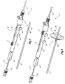
Figure 1 shows a first embodiment of medical grasper according to the present invention; -
Figures 2 the operation of the medical grasper shown inFigure 1 ; -
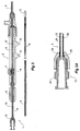
Figure 3 shows a longitudinal cross sectional view of the medical grasper shown inFigure 1 ; -
Figures 3A to 3D show cross sectional details of various portions of the device shown inFigure 3 ; -
Figure 4 shows a longitudinal cross sectional view of the medical grasper shown inFigure 2 ; -
Figures 5A to 5C shows various stages of the deployment of the grasping members in end view; -
Figures 6A to 6C shows various stages of the deployment of the grasping members in side view; -
Figure 7 shows a schematic view of the grasping member expanded into a vessel. -
Figure 8 shows the detail of one embodiment of the grasping member and fastening of the grasping member onto the control member; -
Figure 9 shows another embodiment of grasping member particularly including radio opaque marking on the wire loops; and -
Figure 10 show a detail of the radio opaque marking onto a wire loop. - Throughout this specification the term distal with respect to a portion of the medical grasping device means the end of the medical grasping device further away from the user and the term proximal means the portion of the medical grasping device closer to the user.
- Now looking more closely at the drawings and first in relation to the embodiment shown in
Figures 1 to 4 , it will be seen that themedical grasper 1 includes acontrol assembly 2 and asheath 3 extending from the control assembly. Thecontrol assembly 2 comprises a fixedhandle 5 and a slidinghandle 7. Thecontrol assembly 2 includesgripper protrusions 6 on the fixedhandle 5 to enable a physician to grip the fixed handle. - A
control member 9, which can be particularly seen inFigures 3 and4 , extends from adistal end 11 of the medical graspingdevice 1 through thesheath 3 and is affixed to the slidinghandle 7 in thecontrol assembly 2. Thecontrol member 9 then extends further through thecontrol assembly 2 via alocking pin vice 8 to aLuer lock connector 13 at the proximal end of the medical grasping device. The pin vice enables the control member to be locked in a set position. This is particularly useful during advancement and retraction of the medical grasper through the vasculature. - The distal end of the
control member 9 in this embodiment terminates in anatraumatic tip 15. Thecontrol member 9 comprises acannula 10 with alongitudinal lumen 12 therethrough through which a guide wire can be passed. The medical grasping device can be deployed over a guide wire by extending the guide wire through thelumen 12 of thecontrol member 9. At the distal end of thesheath 3 and there is a radioopaque marker 19 on thecontrol member 9 just proximal of theatraumatic tip 15. The atraumatic tip may be formed from soft nylon or radio opaque urethane material. - As can be seen in
Figures 2 and4 , the slidinghandle 7 has been moved towards the distal end of thecontrol assembly 2 alongelongate slot 4 in the fixedhandle 5 and this has extended thecontrol member 9 distally to expose a graspingmember 17. InFigure 1 the grasping member is trapped between thesheath 3 and thecontrol member 9 but when the control member is extended distally, the graspingmember 17 can expand out. The grasping member comprises a plurality of wires of a shape memory material, which are formed into the extended shape as shown inFigure 2 and then withdrawn into the sheath as shown inFigure 1 for deployment. More detail of the grasping member is shown inFigures 5 to 8 . - The medical grasping device disclosed herein is used to grasp objects and particularly guide wires or the like within a lumen of the human or animal body. The medical grasping device is deployed over a guide wire into a lumen of the body in the form shown in
Figure 1 and then the graspingmember 17 is extended as shown inFigure 2 . The article such as a guide wire to be grasped is then deployed so that the guide wire extends through the loops of the grasping member and then the slidinghandle 7 is retracted to retract the grasping member loops into the sheath until the guide wire has been trapped by the loops and grasped by the engagement of thesheath 3 with the loops of the graspingmember 17, and then the guide wire can be withdrawn from the lumen by withdrawal of the whole device, while keeping tension on the slidinghandle 7 to prevent release of theguide wire 19. Advantageously thepin vice 8 is tightened before retraction to assist with maintaining grip on the grasped object. - The
control member 9 is a composite construction consisting of a flexible tube surrounded by a more rigid tube as shown in detail inFigure 3A . At its proximal end the more rigid tube of thecontrol member 9 extends from theLuer lock connector 13 at the proximal end of the medical grasping device through thecontrol assembly 2 and partially into thesheath 3. The flexible tube can be constructed from a 4.1 French braided nylon catheter and the more rigid tube can be a stainless steel catheter. Both catheters are flared at their proximal ends and clamped into theLuer lock connector 13. The sliding handle or knob clamps onto the more rigid tube as shown in detail inFigure 3C . -
Figures 3A to 3D show detail of various portions of the medical grasper and particularly parts of the control assembly. -
Figure 3A shows theLuer lock connector 13 and its connection with thecontrol member 9. Thecontrol member 9 comprises aflexible tube 20 surrounded by a morerigid tube 21. Theflexible tube 20 has thelongitudinal lumen 12 therethrough through which a guide wire can be passed. At their proximal ends 22 they are both flared and clamped between anut 23 and a Luerlock connector body 24. -
Figure 3B shows thepin vice assembly 8. The pin vice assembly comprises aknob 26 with ascrew thread 27 which engages with ascrew thread 29 in the rear of the fixedhandle 5 and by rotation of theknob 26 causes the knob to engage against aclamp member 28 and this in turn causes the clamp member to clamp against the outerrigid tube 21 of thecontrol member 9. This prevents movement of the control member with respect to the fixedhandle 5. -
Figure 3C shows detail of the slidinghandle 7 and its connection with thecontrol member 9. The slidinghandle 7 has agripping knob 31 which engages around a clampingblock 32. The clampingblock 32 has a setscrew 33 which engages against the outerrigid tube 21 of thecontrol member 9. Movement of the slidinghandle 7 along theslot 4 in the fixedhandle 5 will cause the control member to move also provided thepin vice 8 has been disengaged. -
Figure 3D shows a haemostatic seal arrangement between thecontrol member 9 and the fixedhandle 5 and the connection of thesheath 3 with the fixedhandle 5. Thedistal end 35 of the fixedhandle 5 comprises anadaptor 36 with a combination of asilicone washer seal 37 and an O-ring seal 38 engaged between theadaptor 36 and fixedhandle 5. This provides a haemostatic seal for thelumen 39 between thesheath 3 and thecontrol member 9. A flushingport 40 enables supply of flushing fluid into thelumen 39 between thesheath 3 and thecontrol member 9 to allow for instance flushing with sterile saline solution between the elongate control member and the outer sheath to eliminate air, while the device is outside of the patient. Thesheath 3 is clamped onto theadaptor 36 by a clamping nut 41 which engages against a flare 43 at the proximal end of thesheath 3. -
Figures 5A to 5C and6A to 6C show various stages of the deployment of the graspingmember 17 from the end of thesheath 3. The graspingmember 17 comprises a number of loops of a shape memory wire, such as Nitinol™ wire, which are fastened to thecontrol member 9. One method of fastening the wires to the control member is discussed inFigure 8 below. In this embodiment there are four loops ofwire control member 9. Each wire loop extends substantially radially outwards from the control member in afirst portion 58 and then substantially circumferentially in anarcuate portion 59 before extending radially inwards aportion 60 to the approximate diametrically opposite part of thecontrol member 9, as can be best seen inFigure 5C . By this arrangement eachloop -
Figures 5A and6A show an initial stage of deployment where the loops ofwire atraumatic tip 15. -
Figures 5B and6B show a further stage of deployment where the loops ofwire -
Figures 5C and6C show the final stage of deployment where the loops ofwire - By this arrangement, as shown in
Figure 7 where the graspingmember 17 has been deployed into avessel 60, the wire loops of the grasping member extend right out to the walls of the vessel and completely encircle the walls so any device to be gripped which is passed down through the vessel will be encompassed and conveniently gripped. - It will be realised that the deployed diameter of the grasping member should be selected for the expected diameter of the vessel into which the grasping member is to be used.
- One method of affixing the wire loops of the grasping member to the control member according to one embodiment of the present invention is shown in
Figure 8 . - As discussed above, the wire loops of the grasping
member 17 are formed from a shape memory material such as Nitinol™. Before being placed onto thecontrol member 9, the wire loops are formed on a mandrel with adjacent wires ofadjacent loops 62 wound in a series ofspirals 63 around a mandrel and then suitably heat treated. After heat treatment, the mandrel is removed and thecontrol member 9 is deployed through the spiral of wire loops so that the spiral of wire loops grips the control member. A binding 64 is placed around the pairs of adjacent wires to keep them adjacent to thecontrol member 9 and a suitable sealing material can be placed over thespiral 63. -
Figure 9 shows an end on view of another embodiment of graspingmember 71 according to this invention. In this embodiment, each of thewire loops 70 of the graspingmember 71 in itsouter region 72 has formed thereon acoil 74 of fine platinum wire to enhance the radio opaque nature of the wire loops. -
Figure 10 shows a detail of the wire loops with theplatinum wire coil 74 formed thereon. At each end of thecoil 74, a portion of non toxic adhesive 76 is provided to provide a tapered transition from thecoil 74 to thewire 72. - The embodiments of medical grasping device disclosed herein can be useful in any multiple access vascular procedure for adjusting the final position of a medical device, such as through the iliac or subclavian arteries. They can additionally be useful with the liver or kidney or any other nonvascular procedure, especially where access to the site involves a tortuous path, since the grasping device is flexible and is adapted to follow a guide wire.
Claims (14)
- A medical grasping device (1) including:an elongate control member (9) provided with a distal tip (15) and a proximal end portion, said elongate control member including a grasping member (17) proximal said distal tip;an outer sheath (3) with a passageway within which the elongate control member is slidably held;and a control assembly (2) disposed at a proximal end of said outer sheath and said proximal end portion of said elongate control member and operable to urge said grasping member out from and into a distal end of said outer sheath;said grasping member (17, 71) comprising four pre-formed wire loops (50, 52, 54, 56, 70) approximately equally spaced angularly about a longitudinal axis of said elongate control member (9), which self-deploy from said distal end of said outer sheath, respective ends of each wire loop being fastened to the elongate control member; wherein said wire loops, when deployed, extend in different directions and wherein adjacent wire loops overlap with one another;
characterized in that each of said wire loops is substantially semicircular when fully deployed and each wire loop overlaps its neighbour on either side by approximately one quarter of a total circle area so as to provide a generally round grasping member. - A grasping device (1) according claim 1, wherein said elongate control member is a flexible cannula (9) providing a lumen extending therethrough into which a guide wire (19) is slidably receivable.
- A grasping device (1) according to claim 1 or 2, wherein said outer sheath (3) is flexible and kink-resistant and has a lubricious outer and/or inner surface.
- A grasping device (1) according to claim 1, 2 or 3, wherein said control assembly includes a grippable actuation element (7) reciprocally movable along a handle (5) to actuate said elongate control member (9) with respect to said outer sheath (3) to deploy and retract said grasping member (17).
- A grasping device (1) according to claim 4, wherein said actuation section (7) includes a connecting block (32) affixed to said elongate control member (9) and is disposed within a longitudinal slot (4) of said handle (5).
- A grasping device (1) according to any preceding claim, wherein said control member includes an outer rigid tube (21) and an inner flexible tube (20), the rigid tube extending through the control assembly and into the outer sheath and moveable therethrough.
- A grasping device (1) according to any preceding claim, wherein said wire loops (50, 52, 54, 56, 70) are formed from a shape memory or superelastic metal or alloy, optionally wherein said wire loops (50, 52, 54, 56, 70) are formed of Nitinol.
- A grasping device (1) according to any preceding claim, wherein the wire loops (50, 52, 54, 56, 70) have proximal end portions that are joined to said elongate control member (9) at an affixation point and said loops initially extend along said elongate control member even when said wire loops emerge from said distal end of said outer sheath (3) and self-deploy transversely of said grasping device (17, 71).
- A grasping device (1) according to claim 8, wherein the affixation point comprises a spiral (63) of the wire from the wire loops (50, 52, 54, 56, 70) wound around the elongate control member (9).
- A grasping device (1) according to any preceding claim, wherein said distal tip (15) comprises an atraumatic section.
- A grasping device (1) according to any preceding claim, wherein at least one of said wire loops (50, 52, 54, 56, 70) includes a radio-opaque material.
- A grasping device (1) according to claim 11, wherein the radio-opaque material comprises a coil (74) of platinum wire around and extending along the curved outer section of at least one of said loops.
- A grasping device (1) according to any preceding claim, including a port fitting (40) on the control assembly between the elongate control member and the outer sheath operable to allow flushing with fluid to eliminate air.
- A grasping device (1) according to claim 13, comprising a haemostatic seal (36, 37, 38) between the control assembly and the control member.
Applications Claiming Priority (2)
| Application Number | Priority Date | Filing Date | Title |
|---|---|---|---|
| US78412606P | 2006-03-20 | 2006-03-20 | |
| PCT/US2007/006890 WO2007109257A2 (en) | 2006-03-20 | 2007-03-20 | Medical grasping device |
Publications (3)
| Publication Number | Publication Date |
|---|---|
| EP1996089A2 EP1996089A2 (en) | 2008-12-03 |
| EP1996089B1 true EP1996089B1 (en) | 2016-08-24 |
| EP1996089B8 EP1996089B8 (en) | 2016-10-12 |
Family
ID=38512232
Family Applications (1)
| Application Number | Title | Priority Date | Filing Date |
|---|---|---|---|
| EP07753512.8A Active EP1996089B8 (en) | 2006-03-20 | 2007-03-20 | Medical grasping device |
Country Status (5)
| Country | Link |
|---|---|
| EP (1) | EP1996089B8 (en) |
| JP (1) | JP5186659B2 (en) |
| AU (1) | AU2007227295B2 (en) |
| CA (1) | CA2647106C (en) |
| WO (1) | WO2007109257A2 (en) |
Cited By (5)
| Publication number | Priority date | Publication date | Assignee | Title |
|---|---|---|---|---|
| US9731113B2 (en) | 2014-12-30 | 2017-08-15 | The Spectranetics Corporation | Collapsing coil coupling for lead extension and extraction |
| US9884184B2 (en) | 2014-12-30 | 2018-02-06 | The Spectranetics Corporation | Wire hook coupling for lead extension and extraction |
| US9918729B2 (en) | 2009-09-14 | 2018-03-20 | The Spectranetics Corporation | Snaring systems and methods |
| US10105533B2 (en) | 2014-12-30 | 2018-10-23 | The Spectranetics Corporation | Multi-loop coupling for lead extension and extraction |
| US11357977B2 (en) | 2014-12-30 | 2022-06-14 | Spectranetics Llc | Expanding coil coupling for lead extension and extraction |
Families Citing this family (6)
| Publication number | Priority date | Publication date | Assignee | Title |
|---|---|---|---|---|
| US10426501B2 (en) * | 2012-01-13 | 2019-10-01 | Crux Biomedical, Inc. | Retrieval snare device and method |
| EP2934650B1 (en) * | 2012-12-19 | 2018-03-07 | Muffin Incorporated | Apparatus for the retrieval of an intravascular filter |
| US20160022291A1 (en) * | 2013-03-15 | 2016-01-28 | Volcano Corporation | Retrieval and centering device and method with pressure and ultrasound features |
| AU2016291678B2 (en) * | 2015-07-15 | 2019-03-14 | Corinnova Incorporated | Self-expanding heart assist device |
| WO2017124169A1 (en) | 2016-01-21 | 2017-07-27 | Kardium Inc. | Medical device flushing systems and methods |
| EP3790617B1 (en) * | 2018-05-10 | 2023-10-11 | Kardium Inc. | Catheter sheath devices |
Family Cites Families (6)
| Publication number | Priority date | Publication date | Assignee | Title |
|---|---|---|---|---|
| US5098440A (en) * | 1990-08-14 | 1992-03-24 | Cordis Corporation | Object retrieval method and apparatus |
| US6468291B2 (en) * | 1999-07-16 | 2002-10-22 | Baff Llc | Emboli filtration system having integral strut arrangement and methods of use |
| WO2002036025A1 (en) * | 2000-11-03 | 2002-05-10 | Cook Incorporated | Medical grasping device |
| US7041108B2 (en) * | 2002-05-28 | 2006-05-09 | Lippitt Extractor Company, Llc | Grasper mechanism with biased fixed flexure elements |
| JP4112911B2 (en) * | 2002-06-19 | 2008-07-02 | テルモ株式会社 | Intravascular foreign matter removal wire and medical device |
| US7344550B2 (en) * | 2003-10-21 | 2008-03-18 | Boston Scientific Scimed, Inc. | Clot removal device |
-
2007
- 2007-03-20 JP JP2009501504A patent/JP5186659B2/en active Active
- 2007-03-20 CA CA2647106A patent/CA2647106C/en active Active
- 2007-03-20 EP EP07753512.8A patent/EP1996089B8/en active Active
- 2007-03-20 AU AU2007227295A patent/AU2007227295B2/en active Active
- 2007-03-20 WO PCT/US2007/006890 patent/WO2007109257A2/en not_active Ceased
Non-Patent Citations (1)
| Title |
|---|
| None * |
Cited By (10)
| Publication number | Priority date | Publication date | Assignee | Title |
|---|---|---|---|---|
| US9918729B2 (en) | 2009-09-14 | 2018-03-20 | The Spectranetics Corporation | Snaring systems and methods |
| US10687836B2 (en) | 2009-09-14 | 2020-06-23 | Spectranetics Llc | Snaring systems and methods |
| US9731113B2 (en) | 2014-12-30 | 2017-08-15 | The Spectranetics Corporation | Collapsing coil coupling for lead extension and extraction |
| US9884184B2 (en) | 2014-12-30 | 2018-02-06 | The Spectranetics Corporation | Wire hook coupling for lead extension and extraction |
| US10105533B2 (en) | 2014-12-30 | 2018-10-23 | The Spectranetics Corporation | Multi-loop coupling for lead extension and extraction |
| US10391300B2 (en) | 2014-12-30 | 2019-08-27 | The Spectranetics Corporation | Collapsing coil coupling for lead extension and extraction |
| US10864370B2 (en) | 2014-12-30 | 2020-12-15 | Koninklijke Philips N.V. | Multi-loop coupling for lead extension and extraction |
| US11173298B2 (en) | 2014-12-30 | 2021-11-16 | Spectranetics Llc. | Collapsing coil coupling for lead extension and extraction |
| US11357977B2 (en) | 2014-12-30 | 2022-06-14 | Spectranetics Llc | Expanding coil coupling for lead extension and extraction |
| US11826563B2 (en) | 2014-12-30 | 2023-11-28 | Koninklijke Philips N.V. | Expanding tube coupling for reversible lead locking |
Also Published As
| Publication number | Publication date |
|---|---|
| WO2007109257A2 (en) | 2007-09-27 |
| WO2007109257A3 (en) | 2007-11-29 |
| AU2007227295B2 (en) | 2012-04-05 |
| JP2009530030A (en) | 2009-08-27 |
| AU2007227295A1 (en) | 2007-09-27 |
| EP1996089A2 (en) | 2008-12-03 |
| CA2647106C (en) | 2014-12-09 |
| JP5186659B2 (en) | 2013-04-17 |
| CA2647106A1 (en) | 2007-09-27 |
| EP1996089B8 (en) | 2016-10-12 |
Similar Documents
| Publication | Publication Date | Title |
|---|---|---|
| US7753918B2 (en) | Medical grasping device | |
| CA2647106C (en) | Medical grasping device | |
| EP1330194B1 (en) | Medical grasping device | |
| EP0708621B1 (en) | Dual coil medical retrieval device | |
| EP3017794B1 (en) | Deployment handle for a prosthesis delivery device | |
| EP2675410B1 (en) | Implant retrieval device | |
| US9968358B2 (en) | Implant delivery system | |
| US7713275B2 (en) | Medical grasping device | |
| US8512351B2 (en) | Releasable medical basket and related methods of use | |
| US8715227B2 (en) | Multi-stranded apparatus for treating a medical condition | |
| JP3184735B2 (en) | Device for introducing a stent or stent-graft | |
| US7753917B2 (en) | Medical grasping device | |
| CN102137644B (en) | Introducer for endovascular implants | |
| JP2003521996A (en) | Apparatus and method for delivery of endovascular prostheses | |
| JP5703459B2 (en) | Device for mounting an implantable medical device | |
| US7727253B2 (en) | Medical grasping device having embolic protection | |
| US8398663B2 (en) | Valvulotome device and method | |
| CN102933161A (en) | Method and device for treating cerebrovascular pathologies and delivery system therefor | |
| EP2529704B1 (en) | Prosthesis delivery system | |
| US11051961B2 (en) | Deployment handle with stabilizing rail for a pre-loaded prosthesis delivery device |
Legal Events
| Date | Code | Title | Description |
|---|---|---|---|
| PUAI | Public reference made under article 153(3) epc to a published international application that has entered the european phase |
Free format text: ORIGINAL CODE: 0009012 |
|
| 17P | Request for examination filed |
Effective date: 20080922 |
|
| AK | Designated contracting states |
Kind code of ref document: A2 Designated state(s): AT BE BG CH CY CZ DE DK EE ES FI FR GB GR HU IE IS IT LI LT LU LV MC MT NL PL PT RO SE SI SK TR |
|
| RIN1 | Information on inventor provided before grant (corrected) |
Inventor name: DUCKE, WERNER, D. Inventor name: FRYE, MARK, R. Inventor name: HARTLEY, DAVID, ERNEST Inventor name: IVANCEV, KRASNODAR Inventor name: DEBRUYNE, MICHAEL, P. Inventor name: DIAMOND, JARETT |
|
| RAP1 | Party data changed (applicant data changed or rights of an application transferred) |
Owner name: COOK MEDICAL TECHNOLOGIES LLC Owner name: WILLIAM A. COOK AUSTRALIA PTY. LTD. |
|
| RAP1 | Party data changed (applicant data changed or rights of an application transferred) |
Owner name: WILLIAM A. COOK AUSTRALIA PTY. LTD. Owner name: COOK MEDICAL TECHNOLOGIES LLC |
|
| 17Q | First examination report despatched |
Effective date: 20120611 |
|
| DAX | Request for extension of the european patent (deleted) | ||
| GRAP | Despatch of communication of intention to grant a patent |
Free format text: ORIGINAL CODE: EPIDOSNIGR1 |
|
| INTG | Intention to grant announced |
Effective date: 20160404 |
|
| GRAJ | Information related to disapproval of communication of intention to grant by the applicant or resumption of examination proceedings by the epo deleted |
Free format text: ORIGINAL CODE: EPIDOSDIGR1 |
|
| GRAR | Information related to intention to grant a patent recorded |
Free format text: ORIGINAL CODE: EPIDOSNIGR71 |
|
| GRAS | Grant fee paid |
Free format text: ORIGINAL CODE: EPIDOSNIGR3 |
|
| GRAA | (expected) grant |
Free format text: ORIGINAL CODE: 0009210 |
|
| INTC | Intention to grant announced (deleted) | ||
| AK | Designated contracting states |
Kind code of ref document: B1 Designated state(s): AT BE BG CH CY CZ DE DK EE ES FI FR GB GR HU IE IS IT LI LT LU LV MC MT NL PL PT RO SE SI SK TR |
|
| INTG | Intention to grant announced |
Effective date: 20160720 |
|
| REG | Reference to a national code |
Ref country code: GB Ref legal event code: FG4D |
|
| REG | Reference to a national code |
Ref country code: CH Ref legal event code: EP |
|
| RAP2 | Party data changed (patent owner data changed or rights of a patent transferred) |
Owner name: COOK MEDICAL TECHNOLOGIES LLC |
|
| REG | Reference to a national code |
Ref country code: AT Ref legal event code: REF Ref document number: 822329 Country of ref document: AT Kind code of ref document: T Effective date: 20160915 |
|
| REG | Reference to a national code |
Ref country code: IE Ref legal event code: FG4D |
|
| REG | Reference to a national code |
Ref country code: DE Ref legal event code: R096 Ref document number: 602007047609 Country of ref document: DE |
|
| REG | Reference to a national code |
Ref country code: LT Ref legal event code: MG4D |
|
| REG | Reference to a national code |
Ref country code: NL Ref legal event code: MP Effective date: 20160824 |
|
| REG | Reference to a national code |
Ref country code: AT Ref legal event code: MK05 Ref document number: 822329 Country of ref document: AT Kind code of ref document: T Effective date: 20160824 |
|
| PG25 | Lapsed in a contracting state [announced via postgrant information from national office to epo] |
Ref country code: NL Free format text: LAPSE BECAUSE OF FAILURE TO SUBMIT A TRANSLATION OF THE DESCRIPTION OR TO PAY THE FEE WITHIN THE PRESCRIBED TIME-LIMIT Effective date: 20160824 Ref country code: IT Free format text: LAPSE BECAUSE OF FAILURE TO SUBMIT A TRANSLATION OF THE DESCRIPTION OR TO PAY THE FEE WITHIN THE PRESCRIBED TIME-LIMIT Effective date: 20160824 Ref country code: LT Free format text: LAPSE BECAUSE OF FAILURE TO SUBMIT A TRANSLATION OF THE DESCRIPTION OR TO PAY THE FEE WITHIN THE PRESCRIBED TIME-LIMIT Effective date: 20160824 Ref country code: FI Free format text: LAPSE BECAUSE OF FAILURE TO SUBMIT A TRANSLATION OF THE DESCRIPTION OR TO PAY THE FEE WITHIN THE PRESCRIBED TIME-LIMIT Effective date: 20160824 |
|
| PG25 | Lapsed in a contracting state [announced via postgrant information from national office to epo] |
Ref country code: GR Free format text: LAPSE BECAUSE OF FAILURE TO SUBMIT A TRANSLATION OF THE DESCRIPTION OR TO PAY THE FEE WITHIN THE PRESCRIBED TIME-LIMIT Effective date: 20161125 Ref country code: ES Free format text: LAPSE BECAUSE OF FAILURE TO SUBMIT A TRANSLATION OF THE DESCRIPTION OR TO PAY THE FEE WITHIN THE PRESCRIBED TIME-LIMIT Effective date: 20160824 Ref country code: PT Free format text: LAPSE BECAUSE OF FAILURE TO SUBMIT A TRANSLATION OF THE DESCRIPTION OR TO PAY THE FEE WITHIN THE PRESCRIBED TIME-LIMIT Effective date: 20161226 Ref country code: SE Free format text: LAPSE BECAUSE OF FAILURE TO SUBMIT A TRANSLATION OF THE DESCRIPTION OR TO PAY THE FEE WITHIN THE PRESCRIBED TIME-LIMIT Effective date: 20160824 Ref country code: LV Free format text: LAPSE BECAUSE OF FAILURE TO SUBMIT A TRANSLATION OF THE DESCRIPTION OR TO PAY THE FEE WITHIN THE PRESCRIBED TIME-LIMIT Effective date: 20160824 Ref country code: AT Free format text: LAPSE BECAUSE OF FAILURE TO SUBMIT A TRANSLATION OF THE DESCRIPTION OR TO PAY THE FEE WITHIN THE PRESCRIBED TIME-LIMIT Effective date: 20160824 |
|
| REG | Reference to a national code |
Ref country code: DE Ref legal event code: R081 Ref document number: 602007047609 Country of ref document: DE Owner name: COOK MEDICAL TECHNOLOGIES LLC, BLOOMINGTON, US Free format text: FORMER OWNERS: COOK MEDICAL TECHNOLOGIES LLC, BLOOMINGTON, IND., US; WILLIAM A. COOK AUSTRALIA PTY. LTD., EIGHT MILES PLAINS, BRISBANE, QUEENSLAND, AU |
|
| PG25 | Lapsed in a contracting state [announced via postgrant information from national office to epo] |
Ref country code: RO Free format text: LAPSE BECAUSE OF FAILURE TO SUBMIT A TRANSLATION OF THE DESCRIPTION OR TO PAY THE FEE WITHIN THE PRESCRIBED TIME-LIMIT Effective date: 20160824 Ref country code: EE Free format text: LAPSE BECAUSE OF FAILURE TO SUBMIT A TRANSLATION OF THE DESCRIPTION OR TO PAY THE FEE WITHIN THE PRESCRIBED TIME-LIMIT Effective date: 20160824 |
|
| REG | Reference to a national code |
Ref country code: DE Ref legal event code: R097 Ref document number: 602007047609 Country of ref document: DE |
|
| PG25 | Lapsed in a contracting state [announced via postgrant information from national office to epo] |
Ref country code: BE Free format text: LAPSE BECAUSE OF FAILURE TO SUBMIT A TRANSLATION OF THE DESCRIPTION OR TO PAY THE FEE WITHIN THE PRESCRIBED TIME-LIMIT Effective date: 20160824 Ref country code: CZ Free format text: LAPSE BECAUSE OF FAILURE TO SUBMIT A TRANSLATION OF THE DESCRIPTION OR TO PAY THE FEE WITHIN THE PRESCRIBED TIME-LIMIT Effective date: 20160824 Ref country code: DK Free format text: LAPSE BECAUSE OF FAILURE TO SUBMIT A TRANSLATION OF THE DESCRIPTION OR TO PAY THE FEE WITHIN THE PRESCRIBED TIME-LIMIT Effective date: 20160824 Ref country code: SK Free format text: LAPSE BECAUSE OF FAILURE TO SUBMIT A TRANSLATION OF THE DESCRIPTION OR TO PAY THE FEE WITHIN THE PRESCRIBED TIME-LIMIT Effective date: 20160824 Ref country code: BG Free format text: LAPSE BECAUSE OF FAILURE TO SUBMIT A TRANSLATION OF THE DESCRIPTION OR TO PAY THE FEE WITHIN THE PRESCRIBED TIME-LIMIT Effective date: 20161124 Ref country code: PL Free format text: LAPSE BECAUSE OF FAILURE TO SUBMIT A TRANSLATION OF THE DESCRIPTION OR TO PAY THE FEE WITHIN THE PRESCRIBED TIME-LIMIT Effective date: 20160824 |
|
| PLBE | No opposition filed within time limit |
Free format text: ORIGINAL CODE: 0009261 |
|
| STAA | Information on the status of an ep patent application or granted ep patent |
Free format text: STATUS: NO OPPOSITION FILED WITHIN TIME LIMIT |
|
| 26N | No opposition filed |
Effective date: 20170526 |
|
| PG25 | Lapsed in a contracting state [announced via postgrant information from national office to epo] |
Ref country code: SI Free format text: LAPSE BECAUSE OF FAILURE TO SUBMIT A TRANSLATION OF THE DESCRIPTION OR TO PAY THE FEE WITHIN THE PRESCRIBED TIME-LIMIT Effective date: 20160824 |
|
| REG | Reference to a national code |
Ref country code: CH Ref legal event code: PL |
|
| PG25 | Lapsed in a contracting state [announced via postgrant information from national office to epo] |
Ref country code: MC Free format text: LAPSE BECAUSE OF FAILURE TO SUBMIT A TRANSLATION OF THE DESCRIPTION OR TO PAY THE FEE WITHIN THE PRESCRIBED TIME-LIMIT Effective date: 20160824 |
|
| REG | Reference to a national code |
Ref country code: FR Ref legal event code: ST Effective date: 20171130 |
|
| PG25 | Lapsed in a contracting state [announced via postgrant information from national office to epo] |
Ref country code: LU Free format text: LAPSE BECAUSE OF NON-PAYMENT OF DUE FEES Effective date: 20170320 Ref country code: FR Free format text: LAPSE BECAUSE OF NON-PAYMENT OF DUE FEES Effective date: 20170331 |
|
| PG25 | Lapsed in a contracting state [announced via postgrant information from national office to epo] |
Ref country code: CH Free format text: LAPSE BECAUSE OF NON-PAYMENT OF DUE FEES Effective date: 20170331 Ref country code: LI Free format text: LAPSE BECAUSE OF NON-PAYMENT OF DUE FEES Effective date: 20170331 |
|
| PG25 | Lapsed in a contracting state [announced via postgrant information from national office to epo] |
Ref country code: MT Free format text: LAPSE BECAUSE OF NON-PAYMENT OF DUE FEES Effective date: 20170320 |
|
| PG25 | Lapsed in a contracting state [announced via postgrant information from national office to epo] |
Ref country code: HU Free format text: LAPSE BECAUSE OF FAILURE TO SUBMIT A TRANSLATION OF THE DESCRIPTION OR TO PAY THE FEE WITHIN THE PRESCRIBED TIME-LIMIT; INVALID AB INITIO Effective date: 20070320 |
|
| PG25 | Lapsed in a contracting state [announced via postgrant information from national office to epo] |
Ref country code: CY Free format text: LAPSE BECAUSE OF NON-PAYMENT OF DUE FEES Effective date: 20160824 |
|
| PG25 | Lapsed in a contracting state [announced via postgrant information from national office to epo] |
Ref country code: TR Free format text: LAPSE BECAUSE OF FAILURE TO SUBMIT A TRANSLATION OF THE DESCRIPTION OR TO PAY THE FEE WITHIN THE PRESCRIBED TIME-LIMIT Effective date: 20160824 |
|
| PG25 | Lapsed in a contracting state [announced via postgrant information from national office to epo] |
Ref country code: IS Free format text: LAPSE BECAUSE OF FAILURE TO SUBMIT A TRANSLATION OF THE DESCRIPTION OR TO PAY THE FEE WITHIN THE PRESCRIBED TIME-LIMIT Effective date: 20161224 |
|
| P01 | Opt-out of the competence of the unified patent court (upc) registered |
Effective date: 20230602 |
|
| PGFP | Annual fee paid to national office [announced via postgrant information from national office to epo] |
Ref country code: GB Payment date: 20260319 Year of fee payment: 20 |
|
| PGFP | Annual fee paid to national office [announced via postgrant information from national office to epo] |
Ref country code: DE Payment date: 20260320 Year of fee payment: 20 Ref country code: IE Payment date: 20260318 Year of fee payment: 20 |