EP1996086B1 - Low-cost contour cuff for surgical tourniquet systems - Google Patents
Low-cost contour cuff for surgical tourniquet systems Download PDFInfo
- Publication number
- EP1996086B1 EP1996086B1 EP07710741.5A EP07710741A EP1996086B1 EP 1996086 B1 EP1996086 B1 EP 1996086B1 EP 07710741 A EP07710741 A EP 07710741A EP 1996086 B1 EP1996086 B1 EP 1996086B1
- Authority
- EP
- European Patent Office
- Prior art keywords
- cuff
- sheath
- bladder
- fastening
- limb
- Prior art date
- Legal status (The legal status is an assumption and is not a legal conclusion. Google has not performed a legal analysis and makes no representation as to the accuracy of the status listed.)
- Active
Links
Images


Classifications
-
- A—HUMAN NECESSITIES
- A61—MEDICAL OR VETERINARY SCIENCE; HYGIENE
- A61B—DIAGNOSIS; SURGERY; IDENTIFICATION
- A61B17/00—Surgical instruments, devices or methods
- A61B17/12—Surgical instruments, devices or methods for ligaturing or otherwise compressing tubular parts of the body, e.g. blood vessels or umbilical cord
- A61B17/132—Tourniquets
- A61B17/135—Tourniquets inflatable
Definitions
- This invention pertains to pneumatic tourniquet cuffs commonly used for stopping arterial blood flow into a portion of a surgical patient's limb to facilitate the performance of a surgical procedure, and for facilitating intravenous regional anesthesia.
- Typical surgical tourniquet systems of the prior art include a tourniquet cuff which encircles the limb of a surgical patient and a tourniquet instrument which is releasably connected to an inflatable bladder within the tourniquet cuff through a length of tubing, thereby establishing a gas-tight passageway between the cuff and the tourniquet instrument.
- the tourniquet instrument contains a pressurized gas source which is used to inflate and regulate the pressure in the tourniquet cuff above a minimum pressure required to stop arterial blood flow distal to the cuff, for a duration suitably long for the performance of a surgical procedure.
- Many types of surgical tourniquet systems have been described in the prior art, such as those described by McEwen in U.S. Pat. No. 4,469,099 , No. 4,479,494 , No. 5,439,477 and McEwen and Jameson in U.S. Pat. No. 5,556,415 and No. 5,855,589
- Standard cylindrical tourniquet cuffs are ideally suited for application to patients with cylindrical limbs.
- a cylindrical cuff when applied to a patient with a tapered limb, a cylindrical cuff will not optimally match the limb taper, and will typically result in a snug fit proximally and a loose fit distally. Consequently, a cylindrical cuff may prove unable to achieve a bloodless field distal to the cuff at normal pressures or may require a substantially higher and more hazardous inflation pressure to achieve a bloodless field, and when inflated may have a tendency to roll or slide distally on the limb during a surgical procedure.
- some tourniquet cuffs of the prior art are designed to have an arcuate shape, and are commonly called contour cuffs.
- contour cuffs When a contour cuff surrounds a limb having a matching taper, a uniformly snug fit can be achieved between the cuff and the limb from the proximal to distal cuff edges.
- contour cuffs of the prior art are described by Robinette-Lehman in U.S. Pat. No. 4,635,635 , and in commercial products manufactured in accordance with its teachings ('Banana Cuff sterile disposable tourniquet cuffs, Zimmer Arthroscopy Systems, Englewood CO).
- Cuffs described by Robinette-Lehman have an arcuate shape (defined by the distal radius), contain a single fastening system with fixed orientation, and include a rigid plastic stiffener.
- the cuff described in the '635 patent matches only a single limb taper for each particular cuff radius. For a limb with a differing taper, a cuff with a different arcuate shape matching that taper must be selected.
- McEwen '431 describes a cuff with an arcuate shape which overcomes the limitations noted above, by replacing the rigid stiffener with fluted welds in the bladder, and by including a complex pivoting means for securing the cuff around a limb having any one of a wide range of limb tapers at the cuff location.
- McEwen '431 provides increased safety and improved shape-matching over a wide range of limb tapers, it does so by including a number of expensive components and laminated materials, with subassemblies that are labor-intensive and time-consuming to manufacture. As a result, the contour cuff of McEwen '431 has a high cost of manufacture, preventing its cost-effective use as sterile disposable tourniquet cuff for single surgical procedures.
- the prior-art contour cuff described in McEwen '431 employs multiple pivoting velcro-type hook fastening straps attached to D-shaped rings so that they may pivot when the cuff is wrapped around a tapered limb, and align with corresponding velcro-type loop material fastened to the surface of the cuff.
- These D-shaped ring assemblies are in turn attached near one end of the cuff.
- the ring assemblies allow the straps to pivot over a predetermined range when the cuff is wrapped around the limb to fully engage with the corresponding loop material on the outer surface of the cuff.
- Manufacturing the ring assemblies described in McEwen '431 requires relatively large amounts of different materials, and requires numerous labor-intensive steps including cutting, alignment, sewing and welding, all of which must be completed by skilled operators.
- US 2003/036771 A1 discloses a contour cuff apparatus for surgical tourniquet systems, comprising a flat securing strap having a uniform width.
- FIG. 1 shows the preferred embodiment in a surgical application and depicts contour tourniquet cuff 10 secured circumferentially around a tapered patient limb 12.
- FIG. 2 depicts contour cuff 10 secured circumferentially around a substantially cylindrically shaped patient limb 14.
- contour tourniquet cuff 10 completely encircles patient limb 12 and is inflated by a source of pressurized gas to a pressure that will occlude the flow of arterial blood in patient limb 12 distal to cuff 10.
- Cuff port 15 is comprised of port inlet 16 and tubing 18 and provides a gas tight pneumatic passageway to the inflatable portion of cuff 10.
- Tubing 18 is made from flexible thermoplastic tubing and is permanently bonded to port inlet 16.
- Tubing 18 is fitted with a suitable connector (not shown) to permit attachment to a tourniquet instrument such as that described by McEwen et al. in U.S. Pat. App. Ser. No. 11/122,600 , for the inflation of cuff 10.
- Tubing 18 has a length at least equal to the maximum width of cuff 10 and allows cuff 10 to be used inside a sterile surgical field.
- cuff 10 is a single port cuff, where cuff port 15 provides a single pneumatic passageway to the inflatable portion of cuff 10.
- cuff port 15 provides a single pneumatic passageway to the inflatable portion of cuff 10.
- cuff 10 has a substantially arcuate shape with the width of the cuff reduced near the end edges.
- the arcuate shape of cuff 10 and the degree to which the width near the end edges is reduced are predetermined to allow cuff 10 to be applied to limbs with a predetermined range of tapers such that cuff 10 remains substantially in contact with the limb along its width around the circumference of the limb.
- cuff 10 is secured around the limb by securing straps 20 and 22.
- Securing straps 20 and 22 are non-releasably attached to a non-inflating region of cuff 10 near an end edge.
- Securing straps 20 and 22 have fastening portions which releasably engage with the outer surface of cuff 10 and bending portions which permit the fastening portions to be positioned such that they can completely engage the outer surface within the side edges of cuff 10.
- the outer surface of cuff 10 and the fastening portions of securing straps 20 and 22 are formed from velcro-type materials.
- the outer surface of cuff 10 is a loop type material and the fastening portions of securing straps 20 and 22 are formed from hook type material.
- Limb 14 shown in FIG. 2 has a substantially cylindrical shape and has been selected to represent a limb with the minimum amount of taper to which cuff 10 can be applied. As shown in FIG. 2 , the bending portions of securing straps 20 and 22 twist to permit the fastening portions to move towards the proximal side edge of the cuff so that they may completely engage the outer surface of cuff 10 and maintain their substantially flat shape.
- Limb 12 shown in FIG. 1 has a substantially tapered shape and has been selected to represent a limb with the maximum amount of taper to which cuff 10 can be applied. As shown in FIG. 1 , the bending portions of securing straps 20 and 22 twist to permit the fastening portions to move towards the distal side edge of the cuff so that they may completely engage the outer surface of cuff 10.
- the fastening portions of securing straps 20 and 22 are completely engaged within the side edges of the cuff.
- the materials comprising the outer surface of cuff 10 and the fastening portions of securing straps 20 and 22 have contrasting colors.
- the outer surface of cuff 10 is colored black and the fastening portions of securing straps 20 and 22 are colored white.
- the contrasting colors provide a user of cuff 10 with a visual indication that the securing straps have been correctly positioned within the side edges of the cuff. When the securing straps are correctly positioned the outer surface of the cuff will be clearly visible completely around the perimeter of the ends of the securing straps.
- cuff 10 is constructed of materials that are appropriate for a single-use sterile disposable tourniquet cuff.
- cuff 10 is sterilized at time of manufacture by exposure to a sterilizing agent within a sterilizing process determined to be safe and effective.
- a sterilization agent and process that will not harm the materials or components of cuff 10 is selected by the manufacturer.
- cuff 10 is sterilized by exposure to gamma radiation or electron beam radiation.
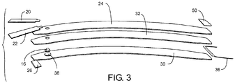
- FIG. 3 is an exploded view of the individual components that are joined together as described below to form cuff 10. For clarity, cuff tubing 18 is not shown in FIG. 3 .
- thermoplastic polymers comprising the components of cuff 10 be prevented from welding at selected surfaces as described below.
- Top sheet 24 forms the outer surface of cuff 10 and is a flexible knit loop nylon material (for example, 200 Series Loop Material, Aplix Inc., Charlotte, NC 28241) adapted for secure engagement with the hook material of the fastening portions of securing straps 20 and 22 and secondary fastener 26. It will be appreciated that top sheet 24 may be made from other types of flexible sheet materials to which velcro-type materials have been permanently attached and that the sheet material may not be completely covered by the velcro-type material. For example top sheet 24 may be comprised of a woven nylon fabric with nylon loop material bonded to the fabric only in predetermined areas for engagement with the fastening portions of securing straps 20 and 22.
- a flexible knit loop nylon material for example, 200 Series Loop Material, Aplix Inc., Charlotte, NC 28241
- top sheet 24 may be made from other types of flexible sheet materials to which velcro-type materials have been permanently attached and that the sheet material may not be completely covered by the velcro-type material.
- top sheet 24 may be comprised of
- Securing straps 20 and 22 are formed from substantially flat flexible inextensible materials, such as the nylon hook material that is commonly used in hook and loop velcro-type fastening applications. As described above, securing straps 20 and 22 have a fastening portion and a bending portion. The bending portion of securing strap 20 and 22 has a width less than the width of the fastening portion, the reduced width of the bending portion allows the bending portion to twist out of its substantially flat shape to facilitate positioning of the fastening portion.
- the fastening portion and bending portion of securing straps 20 and 22 may be comprised of different materials that are permanently joined together to form the securing strap, for example the bending portion may be comprised of a material that is substantially more flexible than the material comprising the fastening portion.
- securing straps 20 and 22 could be comprised of a bending portion formed from a segment of gros-grain ribbon which is permanently joined to a fastening portion formed from a segment of nylon hook material.
- the material comprising the fastening portion of securing straps 20 and 22 is a contrasting color to the material comprising top sheet 24.
- Secondary fastener 26 is comprised of hook material similar to the hook material that forms the fastening portions of securing straps 20 and 22. Secondary fastener 26 is attached to the outer surface of bottom sheet 30 and engages with the loop material of top sheet 24. Secondary fastener 26 facilitates cuff application and alignment by providing a means for maintaining cuff 10 in position around patient limb 12 while securing straps 20 and 22 are positioned and engaged. The additional fastening surface area provided by secondary fastener 26 allows the length of securing straps to be reduced from what otherwise would be required to maintain cuff 10 secured around a limb and thereby increases the range of limb tapers to which cuff 10 can be applied. Secondary fastener 26 also helps improve the stability of cuff 10 on the limb by resisting lateral movement of the overlapped cuff end.
- Bottom sheet 30 and middle sheet 32 are made of a flexible woven nylon cloth coated on one surface with a thermoplastic polymer (for example, 70 Denier nylon cloth coated with thermoplastic polyurethane 0.004" thick).
- the thermoplastic polymer coating prevents the passage of gas through bottom sheet 30 and middle sheet 32 and allows bottom sheet 30 to be welded to middle sheet 32 in selected areas to form an inflatable bladder 34 as shown in cross-section in FIG. 5 .
- the thermoplastic coating on bottom sheet 30 and middle sheet 32 is polyurethane, but it will be appreciated by those skilled in the art that other thermoplastic polymers may be used as coatings on bottom sheet 30 and middle sheet 32 providing they can be joined with sufficient strength to maintain the integrity of cuff 10 when inflated.
- Tie strap 36 is a soft fabric polymer coated ribbon material (Grosgrain 5/8" wide, Dynatex Textiles Inc., Toronto, Ontario, Canada) that is shown in FIG. 3 positioned between middle sheet 32 and bottom sheet 30 at an end edge of cuff 10.
- Tie strap 36 is secured to bottom sheet 30 and middle sheet 32 by welds and provides a means for the user to align and pull cuff 10 snug around the limb.
- tie strap 36 may also be positioned between top sheet 24 and middle sheet 32 near an end edge of cuff 10 and secured by stitching at the side edges of cuff 10.
- port inlet 16 has a right angle configuration and has a flange for bonding with middle sheet 32.
- Port inlet 16 is made of a thermoplastic polymer that is compatible with and can be welded to the thermoplastic coating of middle sheet 32 to form a gas-tight seal.
- Port mask 38 is interposed between port inlet 16 and bottom sheet 30.
- port mask 38 is formed from the same material as bottom sheet 30.
- port mask 38 is placed below port inlet 16 such that the polyurethane coated surface of port mask 38 is facing the polyurethane surface of bottom sheet 30 and the nylon cloth surface is facing port inlet 16.
- port mask 38 bonds to bottom sheet 30 in the region of the weld area joining the flange of port inlet 16 to middle sheet 32 and forms port mask weld 40 as shown in the cross-section of cuff 10 depicted in FIG. 5 .
- Port mask weld 40 secures port mask 38 within inflatable bladder 34 preventing it from interfering with the inflation and deflation of inflatable bladder 34.
- the nylon fabric surface of port mask 38 is not compatible with the material comprising port inlet 16 and thereby prevents port inlet 16 from bonding to the top surface of port mask 38 during the welding operation.
- FIG. 4 is a top view of the preferred embodiment laid flat and shows the areas where middle sheet 32 is welded to bottom sheet 30 and port inlet 16. Port inlet 16 is welded to middle sheet 32 at port weld 42. Middle sheet 32 is also welded to bottom sheet 30 at bladder perimeter weld 44, non-inflating region weld 46, and flute welds 48. Top sheet 24 is secured to middle sheet 32 and bottom sheet 30 by stitching 50 around the perimeter of top sheet 24 as shown in FIG. 5 .
- Bladder perimeter weld 44 defines inflatable bladder 34 of cuff 10 which is shown in cross-section in FIG. 5 .
- Bladder 34 has distal and proximal side edges; the proximal side edge of bladder 34 has a greater radius than the distal side edge of bladder 34.
- bladder perimeter weld 44 has a greater width along the distal side edge of bladder 34 than it has along the proximal side edge of bladder 34. The increased width of the bladder perimeter weld along the distal edge of bladder 34 acts to stiffen the edge of the cuff and thereby help improve the cuffs roll stability when inflated. Only the width of the bladder weld along the distal edge is increased as inflated cuffs tend to roll only distally down the limb.
- the width of the inflatable bladder is maximized for a given overall cuff width.
- Prior art cylindrical cuffs that are substantially rectangular in shape do not have defined proximal and distal side edges; their orientation when applied to a limb is not predetermined by their shape.
- Wide bladder welds in prior art cuffs to improve stability must be made along both side edges of the bladder as the cuff may be applied in either orientation, thereby reducing the maximum possible bladder width for a given cuff width.
- Middle sheet 32 and bottom sheet 30 are joined together by several flute welds 48; these welds are perpendicular to the side edges of cuff 10 and extend radially towards the centerline of cuff 10.
- Flute welds 48 act in place of a stiffing element to constrain inflatable bladder 34 of cuff 10 when inflated.
- Flute welds 48 prevent relative lateral movement between selected areas of bottom sheet 30 and top sheet 24 reducing the tendency of cuff 10 to roll along the longitudinal axis of the limb.
- non-inflating region weld 46 shown in FIG. 4 defines a non-inflating region near an end edge of cuff 10.
- Secondary fastener 26 is attached to the outer surface of bottom sheet 30 by stitching around its perimeter within the non-inflating region.
- Securing straps 20 and 22 are attached to the outer surface of top sheet 24 within the non-inflating region also by stitching.
- the stitching attaching securing straps 20 and 22 passes through the material of secondary fastener 26 which helps to distribute the loads at the attachment points of securing straps 20 and 22 across the end edge of cuff 10.
- securing straps 20 and 22 are attached near the bending portion to the outer surface of top sheet 24 such that they are substantially parallel to the center line of cuff 10.
- Securing strap 20 is attached between the centerline and the proximal side edge of the cuff.
- Securing strap 22 is attached between the centerline and the distal side edge of the cuff.
- the bending portions of securing straps 20 and 22 allow the fastening portions to be placed in positions other than those substantially parallel to the center line of cuff 10.
- securing straps 20 and 22, and secondary fastener 26 may be attached by other mechanical fastening means or by welding or adhesives. It will also be apparent that bladder 34 could be extended eliminating non-inflating region weld 46 and the non-inflating region of the cuff.
- Cuff 10 includes a label 50, shown in FIG. 3 and 4 .
- Label 50 has printed marks to indicate to a user of cuff 10: that cuff 10 is intended for a single use; the proximal and distal side edges of cuff 10; the area of top sheet 24 that secondary fastener 26 and securing straps 20 and 22 are to be completely engaged with.
- Label 50 is comprised of printed Tyvek label material with a thermally activated adhesive backing. Label 50 is die cut to match the shape of cuff 10 near an end edge and adhered to top sheet 24 near an end edge as shown in FIGS. 3 and 4 . The Tyvek material of label 50 does not engage with the hook materials of secondary fastener 26 and securing straps 20 and 22.
- Label 50 acts as a barrier, preventing secondary fastener 26 and securing straps 20 and 22 from engaging with the loop material of top sheet 24 in the region covered by label 50.
- the length of label 50 is selected in the preferred embodiment to be substantially equivalent to or greater than the length of the non-inflating region of cuff 10 to which securing straps 20 and 22 and secondary fastener 26 are fixed.
- Label 50 also acts to stiffen the end edge of cuff 10 and helps prevent the end edge from curling as cuff 10 is pulled snug around a limb by tension on tie strap 36.
- top sheet 24 may be coated with a thermoplastic coating compatible with the coating on bottom sheet 30 and that middle sheet 32 may be eliminated and an inflatable bladder formed between top sheet 24 and bottom sheet 30. This would also eliminate the need for stitching 50 securing top sheet 24 to middle sheet 32 and bottom sheet 30.
- flute welds 48 help improve the roll stability of cuff 10 when inflated on a limb by preventing middle sheet 32 from moving laterally with respect to bottom sheet 30 at selected locations. It will be apparent that flute welds 48 could be replaced by other means to help prevent roll, such as a stiffening sheet made from a thermoplastic material less flexible than middle sheet 32 and having an arcuate shape. A stiffening sheet may be interposed between top sheet 24 and middle sheet 32 or be interposed between middle sheet 32 and bottom sheet 30 within the perimeter of inflatable bladder 34. To further improve stability, the stiffening sheet may be bonded to the inner surface of middle sheet 32 such as described in U.S. Pat. App. No. 11/304,363 .
Landscapes
- Health & Medical Sciences (AREA)
- Life Sciences & Earth Sciences (AREA)
- Surgery (AREA)
- Engineering & Computer Science (AREA)
- Heart & Thoracic Surgery (AREA)
- Vascular Medicine (AREA)
- Nuclear Medicine, Radiotherapy & Molecular Imaging (AREA)
- Hematology (AREA)
- Biophysics (AREA)
- Biomedical Technology (AREA)
- Reproductive Health (AREA)
- Medical Informatics (AREA)
- Molecular Biology (AREA)
- Animal Behavior & Ethology (AREA)
- General Health & Medical Sciences (AREA)
- Public Health (AREA)
- Veterinary Medicine (AREA)
- Surgical Instruments (AREA)
Description
- This invention pertains to pneumatic tourniquet cuffs commonly used for stopping arterial blood flow into a portion of a surgical patient's limb to facilitate the performance of a surgical procedure, and for facilitating intravenous regional anesthesia.
- Typical surgical tourniquet systems of the prior art include a tourniquet cuff which encircles the limb of a surgical patient and a tourniquet instrument which is releasably connected to an inflatable bladder within the tourniquet cuff through a length of tubing, thereby establishing a gas-tight passageway between the cuff and the tourniquet instrument. The tourniquet instrument contains a pressurized gas source which is used to inflate and regulate the pressure in the tourniquet cuff above a minimum pressure required to stop arterial blood flow distal to the cuff, for a duration suitably long for the performance of a surgical procedure. Many types of surgical tourniquet systems have been described in the prior art, such as those described by McEwen in
U.S. Pat. No. 4,469,099 ,No. 4,479,494 ,No. 5,439,477 andMcEwen and Jameson in U.S. Pat. No. 5,556,415 and No.5,855,589 . - Standard cylindrical tourniquet cuffs are ideally suited for application to patients with cylindrical limbs. However, when applied to a patient with a tapered limb, a cylindrical cuff will not optimally match the limb taper, and will typically result in a snug fit proximally and a loose fit distally. Consequently, a cylindrical cuff may prove unable to achieve a bloodless field distal to the cuff at normal pressures or may require a substantially higher and more hazardous inflation pressure to achieve a bloodless field, and when inflated may have a tendency to roll or slide distally on the limb during a surgical procedure. In an effort to match the taper of a patient's limb at a desired cuff location, some tourniquet cuffs of the prior art are designed to have an arcuate shape, and are commonly called contour cuffs. When a contour cuff surrounds a limb having a matching taper, a uniformly snug fit can be achieved between the cuff and the limb from the proximal to distal cuff edges. Wide contour tourniquet cuffs of the prior art have been shown in the surgical literature to substantially reduce pressures required to create a bloodless surgical field distal to the inflated cuff (Younger et al., 'Wide Contoured Thigh Cuffs and Automated Limb Occlusion Measurement Allow Lower Tourniquet Pressures', Clin Orthop 428:286-293, 2004). Lower tourniquet pressures are associated in the surgical literature with lower risk of injuries to surgical patients.
- Examples of contour cuffs of the prior art are described by Robinette-Lehman in
U.S. Pat. No. 4,635,635 , and in commercial products manufactured in accordance with its teachings ('Banana Cuff sterile disposable tourniquet cuffs, Zimmer Arthroscopy Systems, Englewood CO). Cuffs described by Robinette-Lehman have an arcuate shape (defined by the distal radius), contain a single fastening system with fixed orientation, and include a rigid plastic stiffener. The cuff described in the '635 patent matches only a single limb taper for each particular cuff radius. For a limb with a differing taper, a cuff with a different arcuate shape matching that taper must be selected. When the cuff described by Robinette-Lehman '635 is applied to a limb with a differing taper, the overlapping proximal and distal edges of the cuff will not be superimposed upon one another, and will instead need to be skewed to obtain a sufficiently snug application and maximize the contact area between the cuff and the limb. The thick laminate construction and rigid stiffener included by Robinette-Lehman makes skewing the respective overlapping ends of the cuff difficult, and when skewed the orientation of the fixed fastening system may not be appropriate to safely and effectively allow the complete engagement of the velcro-type fastener to secure the cuff on the limb when inflated. - Other contour cuffs of the prior are described by McEwen in
U.S. Pat. No. 5,312,431 ,No. 5,454,831 ,No. 5,578,055 ,No. 5,649,954 , andNo. 5,741,295 . McEwen '431 describes a cuff with an arcuate shape which overcomes the limitations noted above, by replacing the rigid stiffener with fluted welds in the bladder, and by including a complex pivoting means for securing the cuff around a limb having any one of a wide range of limb tapers at the cuff location. Although the cuff described by McEwen '431 provides increased safety and improved shape-matching over a wide range of limb tapers, it does so by including a number of expensive components and laminated materials, with subassemblies that are labor-intensive and time-consuming to manufacture. As a result, the contour cuff of McEwen '431 has a high cost of manufacture, preventing its cost-effective use as sterile disposable tourniquet cuff for single surgical procedures. - The prior-art contour cuff described in McEwen '431 employs multiple pivoting velcro-type hook fastening straps attached to D-shaped rings so that they may pivot when the cuff is wrapped around a tapered limb, and align with corresponding velcro-type loop material fastened to the surface of the cuff. These D-shaped ring assemblies are in turn attached near one end of the cuff. The ring assemblies allow the straps to pivot over a predetermined range when the cuff is wrapped around the limb to fully engage with the corresponding loop material on the outer surface of the cuff. Manufacturing the ring assemblies described in McEwen '431 requires relatively large amounts of different materials, and requires numerous labor-intensive steps including cutting, alignment, sewing and welding, all of which must be completed by skilled operators.
-
US 2003/036771 A1 discloses a contour cuff apparatus for surgical tourniquet systems, comprising a flat securing strap having a uniform width. - There is a need for a contour cuff for surgical tourniquet systems that overcomes the hazards, problems and limitations of performance associated with prior-art contour cuffs, and that can be manufactured at a cost that is substantially lower than prior-art contour cuffs.
-
-
FIG. 1 is a view of the preferred embodiment applied to a tapered patient limb. -
FIG. 2 is a view of the preferred embodiment applied to a cylindrically shaped patient limb. -
FIG. 3 is an exploded view of the preferred embodiment. -
FIG. 4 is a top view of the preferred embodiment. -
FIG. 5 is a section view taken fromFIG. 4 . -
FIG. 1 shows the preferred embodiment in a surgical application and depictscontour tourniquet cuff 10 secured circumferentially around atapered patient limb 12.FIG. 2 depictscontour cuff 10 secured circumferentially around a substantially cylindrically shapedpatient limb 14. - Referring to
FIG. 1 , the inflatable portion ofcontour tourniquet cuff 10 completely encirclespatient limb 12 and is inflated by a source of pressurized gas to a pressure that will occlude the flow of arterial blood inpatient limb 12 distal tocuff 10.Cuff port 15 is comprised ofport inlet 16 andtubing 18 and provides a gas tight pneumatic passageway to the inflatable portion ofcuff 10. Tubing 18 is made from flexible thermoplastic tubing and is permanently bonded toport inlet 16.Tubing 18 is fitted with a suitable connector (not shown) to permit attachment to a tourniquet instrument such as that described byMcEwen et al. in U.S. Pat. App. Ser. No. 11/122,600 , for the inflation ofcuff 10. Tubing 18 has a length at least equal to the maximum width ofcuff 10 and allowscuff 10 to be used inside a sterile surgical field. In the preferred embodiment shown,cuff 10 is a single port cuff, wherecuff port 15 provides a single pneumatic passageway to the inflatable portion ofcuff 10. Those skilled in the art will appreciate that the features described in the preferred embodiment may also be applied to tourniquet cuffs having more than one port, such as those described byU.S. Pat. No. 4,469,099 , No.4,479,494 , and No.5,254,087 . - As shown in
FIGS. 3 and4 cuff 10 has a substantially arcuate shape with the width of the cuff reduced near the end edges. The arcuate shape ofcuff 10 and the degree to which the width near the end edges is reduced are predetermined to allowcuff 10 to be applied to limbs with a predetermined range of tapers such thatcuff 10 remains substantially in contact with the limb along its width around the circumference of the limb. Whencuff 10 is correctly applied to a patient limb as shown inFIGS. 1 and 2 , the side edge ofcuff 10 with the greater radius is proximal and the side edge with the lesser radius is distal on the limb. - As shown in
FIGS. 1 and 2 ,cuff 10 is secured around the limb by securingstraps cuff 10 near an end edge. Securing straps 20 and 22 have fastening portions which releasably engage with the outer surface ofcuff 10 and bending portions which permit the fastening portions to be positioned such that they can completely engage the outer surface within the side edges ofcuff 10. In the preferred embodiment the outer surface ofcuff 10 and the fastening portions of securingstraps cuff 10 is a loop type material and the fastening portions of securingstraps -
Limb 14 shown inFIG. 2 , has a substantially cylindrical shape and has been selected to represent a limb with the minimum amount of taper to whichcuff 10 can be applied. As shown inFIG. 2 , the bending portions of securingstraps cuff 10 and maintain their substantially flat shape. -
Limb 12 shown inFIG. 1 has a substantially tapered shape and has been selected to represent a limb with the maximum amount of taper to whichcuff 10 can be applied. As shown inFIG. 1 , the bending portions of securingstraps cuff 10. - When
cuff 10 is properly secured around a limb the fastening portions of securingstraps cuff 10 and the fastening portions of securingstraps cuff 10 is colored black and the fastening portions of securingstraps cuff 10 with a visual indication that the securing straps have been correctly positioned within the side edges of the cuff. When the securing straps are correctly positioned the outer surface of the cuff will be clearly visible completely around the perimeter of the ends of the securing straps. - As described below,
cuff 10 is constructed of materials that are appropriate for a single-use sterile disposable tourniquet cuff. To permitcuff 10 to be used in a sterile surgical field,cuff 10 is sterilized at time of manufacture by exposure to a sterilizing agent within a sterilizing process determined to be safe and effective. To prevent deterioration of the cuff, and to maintain the integrity of the pneumatic passageways withincuff 10, a sterilization agent and process that will not harm the materials or components ofcuff 10 is selected by the manufacturer. In thepreferred embodiment cuff 10 is sterilized by exposure to gamma radiation or electron beam radiation. - The cost of materials and labor are important considerations in the manufacture of tourniquet cuffs intended for a single use and then disposal. To minimize the cost of materials and assembly of
cuff 10, materials are selected which are not intended to withstand exposure to subsequent sterilization and cleaning processes. The subsequent sterilization or cleaning ofcuff 10 by agents and processes commonly used in health care facilities, such as ethylene oxide gas sterilization, hydrogen peroxide gas sterilization, high temperature and pressure steam sterilization, sterilization by other chemical agents, and pasteurization, are all capable of adversely affecting the integrity of the materials and pneumatic passageways ofcuff 10. -
FIG. 3 is an exploded view of the individual components that are joined together as described below toform cuff 10. For clarity,cuff tubing 18 is not shown inFIG. 3 . - To reduce manufacturing equipment and labor costs it is desirable to manufacture
cuff 10 in a single dielectric welding operation. This requires that the thermoplastic polymers comprising the components ofcuff 10 be prevented from welding at selected surfaces as described below. -
Top sheet 24 forms the outer surface ofcuff 10 and is a flexible knit loop nylon material (for example, 200 Series Loop Material, Aplix Inc., Charlotte, NC 28241) adapted for secure engagement with the hook material of the fastening portions of securingstraps secondary fastener 26. It will be appreciated thattop sheet 24 may be made from other types of flexible sheet materials to which velcro-type materials have been permanently attached and that the sheet material may not be completely covered by the velcro-type material. Forexample top sheet 24 may be comprised of a woven nylon fabric with nylon loop material bonded to the fabric only in predetermined areas for engagement with the fastening portions of securingstraps - Securing straps 20 and 22 are formed from substantially flat flexible inextensible materials, such as the nylon hook material that is commonly used in hook and loop velcro-type fastening applications. As described above, securing
straps strap straps straps straps top sheet 24. -
Secondary fastener 26 is comprised of hook material similar to the hook material that forms the fastening portions of securingstraps Secondary fastener 26 is attached to the outer surface ofbottom sheet 30 and engages with the loop material oftop sheet 24.Secondary fastener 26 facilitates cuff application and alignment by providing a means for maintainingcuff 10 in position aroundpatient limb 12 while securingstraps secondary fastener 26 allows the length of securing straps to be reduced from what otherwise would be required to maintaincuff 10 secured around a limb and thereby increases the range of limb tapers to whichcuff 10 can be applied.Secondary fastener 26 also helps improve the stability ofcuff 10 on the limb by resisting lateral movement of the overlapped cuff end. -
Bottom sheet 30 andmiddle sheet 32 are made of a flexible woven nylon cloth coated on one surface with a thermoplastic polymer (for example, 70 Denier nylon cloth coated with thermoplastic polyurethane 0.004" thick). The thermoplastic polymer coating prevents the passage of gas throughbottom sheet 30 andmiddle sheet 32 and allowsbottom sheet 30 to be welded tomiddle sheet 32 in selected areas to form aninflatable bladder 34 as shown in cross-section inFIG. 5 . In the preferred embodiment the thermoplastic coating onbottom sheet 30 andmiddle sheet 32 is polyurethane, but it will be appreciated by those skilled in the art that other thermoplastic polymers may be used as coatings onbottom sheet 30 andmiddle sheet 32 providing they can be joined with sufficient strength to maintain the integrity ofcuff 10 when inflated. -
Tie strap 36 is a soft fabric polymer coated ribbon material (Grosgrain 5/8" wide, Dynatex Textiles Inc., Toronto, Ontario, Canada) that is shown inFIG. 3 positioned betweenmiddle sheet 32 andbottom sheet 30 at an end edge ofcuff 10.Tie strap 36 is secured tobottom sheet 30 andmiddle sheet 32 by welds and provides a means for the user to align and pullcuff 10 snug around the limb. Whencuff 10 has been secured around a limb the ends oftie strap 36 are tied together to help maintain the overlapping portion of the cuff in alignment around the limb by preventing the cuff from twisting, telescoping and rolling on the limb when inflated. It will be apparent thattie strap 36 may also be positioned betweentop sheet 24 andmiddle sheet 32 near an end edge ofcuff 10 and secured by stitching at the side edges ofcuff 10. - As shown in
FIG. 4 and in cross-section inFIG. 5 ,port inlet 16 has a right angle configuration and has a flange for bonding withmiddle sheet 32.Port inlet 16 is made of a thermoplastic polymer that is compatible with and can be welded to the thermoplastic coating ofmiddle sheet 32 to form a gas-tight seal. -
Port mask 38 is interposed betweenport inlet 16 andbottom sheet 30. In the preferred embodiment,port mask 38 is formed from the same material asbottom sheet 30. - To permit the cost effective manufacture of
cuff 10 it is desirable to form the welds joiningmiddle sheet 32 tobottom sheet 30 andport inlet 16 in a single dielectric welding operation. To preventport inlet 16 from bonding tobottom sheet 30 during the dielectric weldingoperation port mask 38 is placed belowport inlet 16 such that the polyurethane coated surface ofport mask 38 is facing the polyurethane surface ofbottom sheet 30 and the nylon cloth surface is facingport inlet 16. - During the welding operation,
port mask 38 bonds tobottom sheet 30 in the region of the weld area joining the flange ofport inlet 16 tomiddle sheet 32 and formsport mask weld 40 as shown in the cross-section ofcuff 10 depicted inFIG. 5 .Port mask weld 40 securesport mask 38 withininflatable bladder 34 preventing it from interfering with the inflation and deflation ofinflatable bladder 34. The nylon fabric surface ofport mask 38 is not compatible with the material comprisingport inlet 16 and thereby preventsport inlet 16 from bonding to the top surface ofport mask 38 during the welding operation. -
FIG. 4 is a top view of the preferred embodiment laid flat and shows the areas wheremiddle sheet 32 is welded tobottom sheet 30 andport inlet 16.Port inlet 16 is welded tomiddle sheet 32 atport weld 42.Middle sheet 32 is also welded tobottom sheet 30 atbladder perimeter weld 44,non-inflating region weld 46, and flute welds 48.Top sheet 24 is secured tomiddle sheet 32 andbottom sheet 30 by stitching 50 around the perimeter oftop sheet 24 as shown inFIG. 5 . -
Bladder perimeter weld 44 definesinflatable bladder 34 ofcuff 10 which is shown in cross-section inFIG. 5 .Bladder 34 has distal and proximal side edges; the proximal side edge ofbladder 34 has a greater radius than the distal side edge ofbladder 34. In the preferred embodimentbladder perimeter weld 44 has a greater width along the distal side edge ofbladder 34 than it has along the proximal side edge ofbladder 34. The increased width of the bladder perimeter weld along the distal edge ofbladder 34 acts to stiffen the edge of the cuff and thereby help improve the cuffs roll stability when inflated. Only the width of the bladder weld along the distal edge is increased as inflated cuffs tend to roll only distally down the limb. By increasing the width of the bladder weld only along one side edge in the preferred embodiment the width of the inflatable bladder is maximized for a given overall cuff width. Prior art cylindrical cuffs that are substantially rectangular in shape do not have defined proximal and distal side edges; their orientation when applied to a limb is not predetermined by their shape. Wide bladder welds in prior art cuffs to improve stability must be made along both side edges of the bladder as the cuff may be applied in either orientation, thereby reducing the maximum possible bladder width for a given cuff width. -
Middle sheet 32 andbottom sheet 30 are joined together by several flute welds 48; these welds are perpendicular to the side edges ofcuff 10 and extend radially towards the centerline ofcuff 10. Flute welds 48 act in place of a stiffing element to constraininflatable bladder 34 ofcuff 10 when inflated. Flute welds 48 prevent relative lateral movement between selected areas ofbottom sheet 30 andtop sheet 24 reducing the tendency ofcuff 10 to roll along the longitudinal axis of the limb. - The perimeter of
non-inflating region weld 46 shown inFIG. 4 , defines a non-inflating region near an end edge ofcuff 10.Secondary fastener 26 is attached to the outer surface ofbottom sheet 30 by stitching around its perimeter within the non-inflating region. Securing straps 20 and 22 are attached to the outer surface oftop sheet 24 within the non-inflating region also by stitching. The stitching attaching securingstraps secondary fastener 26 which helps to distribute the loads at the attachment points of securingstraps cuff 10. - As shown in
FIG. 4 , securingstraps top sheet 24 such that they are substantially parallel to the center line ofcuff 10. Securingstrap 20 is attached between the centerline and the proximal side edge of the cuff. Securingstrap 22 is attached between the centerline and the distal side edge of the cuff. As described above the bending portions of securingstraps cuff 10. - It will be apparent that securing
straps secondary fastener 26 may be attached by other mechanical fastening means or by welding or adhesives. It will also be apparent thatbladder 34 could be extended eliminatingnon-inflating region weld 46 and the non-inflating region of the cuff. -
Cuff 10 includes alabel 50, shown inFIG. 3 and4 .Label 50 has printed marks to indicate to a user of cuff 10: thatcuff 10 is intended for a single use; the proximal and distal side edges ofcuff 10; the area oftop sheet 24 thatsecondary fastener 26 and securingstraps Label 50 is comprised of printed Tyvek label material with a thermally activated adhesive backing.Label 50 is die cut to match the shape ofcuff 10 near an end edge and adhered totop sheet 24 near an end edge as shown inFIGS. 3 and4 . The Tyvek material oflabel 50 does not engage with the hook materials ofsecondary fastener 26 and securingstraps Label 50 acts as a barrier, preventingsecondary fastener 26 and securingstraps top sheet 24 in the region covered bylabel 50. To insure thatinflatable bladder 34 completely encircles a limb whensecondary fastener 26 and securingstraps top sheet 24, the length oflabel 50 is selected in the preferred embodiment to be substantially equivalent to or greater than the length of the non-inflating region ofcuff 10 to which securing straps 20 and 22 andsecondary fastener 26 are fixed. -
Label 50 also acts to stiffen the end edge ofcuff 10 and helps prevent the end edge from curling ascuff 10 is pulled snug around a limb by tension ontie strap 36. - The preferred embodiment is substantially comprised of
top sheet 24,middle sheet 32 andbottom sheet 30. It will be apparent thattop sheet 24 may be coated with a thermoplastic coating compatible with the coating onbottom sheet 30 and thatmiddle sheet 32 may be eliminated and an inflatable bladder formed betweentop sheet 24 andbottom sheet 30. This would also eliminate the need for stitching 50 securingtop sheet 24 tomiddle sheet 32 andbottom sheet 30. - In the preferred embodiment flute welds 48 help improve the roll stability of
cuff 10 when inflated on a limb by preventingmiddle sheet 32 from moving laterally with respect tobottom sheet 30 at selected locations. It will be apparent that flute welds 48 could be replaced by other means to help prevent roll, such as a stiffening sheet made from a thermoplastic material less flexible thanmiddle sheet 32 and having an arcuate shape. A stiffening sheet may be interposed betweentop sheet 24 andmiddle sheet 32 or be interposed betweenmiddle sheet 32 andbottom sheet 30 within the perimeter ofinflatable bladder 34. To further improve stability, the stiffening sheet may be bonded to the inner surface ofmiddle sheet 32 such as described inU.S. Pat. App. No. 11/304,363 .
Claims (12)
- A low-cost contour cuff apparatus for surgical tourniquet systems, comprising:a sheath containing an inflatable bladder (34) the sheath having an arcuate shape, an outer surface and a centerline equidistant between first and second side edges;a securing strap (20,22) non-releasably attached to the outer surface (24) and formed of flexible and substantially inextensible material having a shape that is predetermined and substantially flat, wherein the strap includes a bending portion near a first strap end and a fastening portion near a second strap end, wherein the fastening portion releasably engages with the outer surface and the fastening portion has a predetermined fastening width dimension and wherein the bending portion permits the fastening portion to be positioned such that the fastening portion can completely engage the outer surface within the side edges of the cuff1 and the bending portion of the securing strap has a width less than the width of the fastening portion, and wherein the bending portion is adapted to allow the bending portion to flex out of the substantially flat shape to facilitate positioning of the fastening portion into any of a plurality of positions in the substantially flat shape; andfastening means for releasably attaching the fastening portion of the securing strap (20,22) to the outer surface (24) whenever the sheath is curved into a position for surrounding a limb(12).
- The apparatus as described in claim 1 wherein the securing strap (20,22) is formed by a bending member having a first predetermined flexibility that is immovably joined to a fastening member having a second predetermined flexibility, wherein the first predetermined flexibility is greater than the second predetermined flexibility.
- The apparatus as described in claim 1 wherein the fastening portion of the securing strap (20,22) carries a first predetermined color contrasting with a second predetermined color carried on the outer surface (24), thereby facilitating visual determination of complete attachment of the fastening portion to the outer surface (24) within the first and second side edges.
- The apparatus as described in claim 1 wherein the sheath has a width dimension between the first and second side edges along the centerline and including port means communicating pneumatically with the inflatable bladder (34), wherein the port means includes flexible thermoplastic tubing (18) having a length at least equal to the maximum width of the sheath, and wherein the port means is releasably connectable to a tourniquet instrument for supplying the bladder (34) with pressurized gas.
- The apparatus as described in claim 4, wherein the sheath, the securing strap (20,22), the fastening means and the port means are sterile.
- The apparatus as described in claim 4 and including the tourniquet instrument for supplying the bladder (34) with pressurized gas.
- The apparatus as described in claim 4 and including a port mask (38), wherein the bladder (34) includes first and second bladder sheets, wherein the port means communicates with the bladder through a port inlet welded to a first bladder sheet, and wherein the port mask (38) is interposed between the port inlet (16) and the second bladder sheet.
- The apparatus as described in claim 1 wherein the sheath has a predetermined flexibility sufficient for surrounding the limb (12), and including stiffening means formed of a sheet having a predetermined flexibility less than the flexibility of the sheath and contained within the bladder (34).
- The apparatus as described in claim 1 wherein the sheath has a predetermined flexibility sufficient for surrounding the limb (12), and including stiffening means formed of a sheet having a predetermined flexibility less than the flexibility of the sheath and contained within the sheath between the outer surface (24) and the bladder (34).
- The apparatus as described in claim 1 wherein the sheath has an inner surface and first and second sheath ends, wherein the cuff (10) includes secondary securing means attached to the inner surface of the sheath near the first sheath end, and wherein the secondary securing means is adapted for releasable attachment to the outer surface whenever the sheath surrounds the limb and overlaps upon itself so that the secondary securing means contacts the outer surface.
- The apparatus as described in claim 10 and including label means covering the outer surface of the sheath near the second sheath end, wherein the label means forms a barrier preventing attachment of the secondary securing means to the outer surface of the sheath.
- The apparatus of claim 1, further comprising:a second securing strap (20,22) non-releasably attached to the outer surface (24) and formed of substantially inextensible material having a shape that is predetermined and substantially flat, wherein the strap includes a bending portion near a first strap end and a fastening portion near a second strap end, and wherein the bending portion is adapted to allow the bending portion to flex out of the substantially flat shape to facilitate positioning of the fastening portion into any of a plurality of positions in the substantially flat shape,wherein the colour of the outer surface of the cuff (10) contrasts with the colour of the fastening portions of the first and second securing straps (20,22).
Applications Claiming Priority (2)
| Application Number | Priority Date | Filing Date | Title |
|---|---|---|---|
| US11/384,695 US7758607B2 (en) | 2006-03-20 | 2006-03-20 | Low-cost contour cuff for surgical tourniquet systems |
| PCT/CA2007/000411 WO2007106979A1 (en) | 2006-03-20 | 2007-03-14 | Low-cost contour cuff for surgical tourniquet systems |
Publications (3)
| Publication Number | Publication Date |
|---|---|
| EP1996086A1 EP1996086A1 (en) | 2008-12-03 |
| EP1996086A4 EP1996086A4 (en) | 2012-04-04 |
| EP1996086B1 true EP1996086B1 (en) | 2017-07-19 |
Family
ID=38518899
Family Applications (1)
| Application Number | Title | Priority Date | Filing Date |
|---|---|---|---|
| EP07710741.5A Active EP1996086B1 (en) | 2006-03-20 | 2007-03-14 | Low-cost contour cuff for surgical tourniquet systems |
Country Status (3)
| Country | Link |
|---|---|
| US (3) | US7758607B2 (en) |
| EP (1) | EP1996086B1 (en) |
| WO (1) | WO2007106979A1 (en) |
Families Citing this family (41)
| Publication number | Priority date | Publication date | Assignee | Title |
|---|---|---|---|---|
| US7871387B2 (en) | 2004-02-23 | 2011-01-18 | Tyco Healthcare Group Lp | Compression sleeve convertible in length |
| GB0515294D0 (en) | 2005-07-26 | 2005-08-31 | Novamedix Distrib Ltd | Limited durability closure means for an inflatable medical garment |
| US8029451B2 (en) | 2005-12-12 | 2011-10-04 | Tyco Healthcare Group Lp | Compression sleeve having air conduits |
| US7780698B2 (en) * | 2005-12-14 | 2010-08-24 | Western Clinical Engineering, Ltd. | Low-cost disposable tourniquet cuff having improved safety |
| US20180116679A1 (en) | 2006-03-20 | 2018-05-03 | Western Clinical Engineering Ltd. | Method and apparatus for shielding engagement of a tourniquet cuff |
| USD608006S1 (en) | 2007-04-09 | 2010-01-12 | Tyco Healthcare Group Lp | Compression device |
| US8506508B2 (en) | 2007-04-09 | 2013-08-13 | Covidien Lp | Compression device having weld seam moisture transfer |
| US8016779B2 (en) | 2007-04-09 | 2011-09-13 | Tyco Healthcare Group Lp | Compression device having cooling capability |
| US8109892B2 (en) | 2007-04-09 | 2012-02-07 | Tyco Healthcare Group Lp | Methods of making compression device with improved evaporation |
| US8029450B2 (en) | 2007-04-09 | 2011-10-04 | Tyco Healthcare Group Lp | Breathable compression device |
| US8070699B2 (en) | 2007-04-09 | 2011-12-06 | Tyco Healthcare Group Lp | Method of making compression sleeve with structural support features |
| US8034007B2 (en) | 2007-04-09 | 2011-10-11 | Tyco Healthcare Group Lp | Compression device with structural support features |
| US8128584B2 (en) | 2007-04-09 | 2012-03-06 | Tyco Healthcare Group Lp | Compression device with S-shaped bladder |
| US8016778B2 (en) | 2007-04-09 | 2011-09-13 | Tyco Healthcare Group Lp | Compression device with improved moisture evaporation |
| US8021388B2 (en) | 2007-04-09 | 2011-09-20 | Tyco Healthcare Group Lp | Compression device with improved moisture evaporation |
| US8162861B2 (en) | 2007-04-09 | 2012-04-24 | Tyco Healthcare Group Lp | Compression device with strategic weld construction |
| US8114117B2 (en) | 2008-09-30 | 2012-02-14 | Tyco Healthcare Group Lp | Compression device with wear area |
| US9788773B2 (en) | 2008-05-21 | 2017-10-17 | Robert J. Perry | Vein presentation enhancement device |
| US9113894B2 (en) | 2008-05-21 | 2015-08-25 | Robert J. Perry | Vein presentation enhancement device |
| US8235923B2 (en) | 2008-09-30 | 2012-08-07 | Tyco Healthcare Group Lp | Compression device with removable portion |
| US9801780B2 (en) * | 2009-06-23 | 2017-10-31 | Lifecuff Technologies Inc. | Methods and devices for remote ischemic conditioning via partial limb occlusion |
| EP2448474B1 (en) * | 2009-06-23 | 2019-09-18 | Boris Leschinsky | Devices for remote ischemic preconditioning and near-continuous blood pressure monitoring |
| EP2496149B1 (en) * | 2009-11-06 | 2017-09-20 | Western Clinical Engineering, Ltd. | Extendible tourniquet cuff with stabilizer for improved utility and safety |
| US8652079B2 (en) | 2010-04-02 | 2014-02-18 | Covidien Lp | Compression garment having an extension |
| US10751221B2 (en) | 2010-09-14 | 2020-08-25 | Kpr U.S., Llc | Compression sleeve with improved position retention |
| US8096964B1 (en) | 2010-09-29 | 2012-01-17 | Tyco Healthcare Group Lp | Compression garment having grip |
| WO2013177342A1 (en) * | 2012-05-23 | 2013-11-28 | Perry Robert J | Vein presentation enhancement device |
| US9205021B2 (en) | 2012-06-18 | 2015-12-08 | Covidien Lp | Compression system with vent cooling feature |
| US9393027B1 (en) * | 2012-08-02 | 2016-07-19 | Frank Gleason I.P., Llc | Intravenous assist device |
| JP6051732B2 (en) * | 2012-09-25 | 2016-12-27 | オムロンヘルスケア株式会社 | Cuff for blood pressure information measuring device and blood pressure information measuring device |
| WO2014145688A2 (en) * | 2013-03-15 | 2014-09-18 | Perry Robert J | Vein presentation enhancement device |
| USD733306S1 (en) | 2014-04-17 | 2015-06-30 | Stephen Brock Blankenship | Compression and tourniquet band |
| US20150327870A1 (en) * | 2014-05-15 | 2015-11-19 | Abbott Cardiovascular Systems, Inc. | Methods, systems, and devices for applying target force to a radial access puncture site |
| DE202016104459U1 (en) | 2016-08-12 | 2017-11-14 | Ulrich Gmbh & Co. Kg | Tourniquet |
| DE102016115027A1 (en) | 2016-08-12 | 2018-02-15 | Ulrich Gmbh & Co. Kg | Tourniquet |
| USD847344S1 (en) * | 2017-12-19 | 2019-04-30 | Western Clinical Engineering Ltd. | Engagement shield for a tourniquet cuff |
| AU2018389598A1 (en) * | 2017-12-22 | 2020-07-09 | Western Clinical Engineering Ltd. | Method and apparatus for shielding engagement of a tourniquet cuff |
| US11185338B2 (en) | 2019-08-26 | 2021-11-30 | Covidien Lp | Compression cuff |
| KR102740271B1 (en) * | 2022-04-26 | 2024-12-06 | 송유찬 | A tourniquet |
| KR102705263B1 (en) * | 2023-09-26 | 2024-09-12 | 주식회사 도움메디칼 | Tourniquet curf assembly for patient |
| US20250121758A1 (en) * | 2023-10-13 | 2025-04-17 | Lear Corporation | Fluid distribution system for a vehicle seat |
Family Cites Families (46)
| Publication number | Priority date | Publication date | Assignee | Title |
|---|---|---|---|---|
| US3467077A (en) * | 1966-06-30 | 1969-09-16 | Dupaco Inc | Sphygmomanometric cuff |
| US3552383A (en) | 1969-01-08 | 1971-01-05 | Ibm | Method and system for estimation of arterial pressure |
| US3654931A (en) * | 1970-02-11 | 1972-04-11 | Kidde & Co Walter | Disposable tourniquet cover |
| US3892229A (en) * | 1973-12-06 | 1975-07-01 | Duane F Taylor | Apparatus for augmenting venous blood flow |
| US4013069A (en) * | 1975-10-28 | 1977-03-22 | The Kendall Company | Sequential intermittent compression device |
| US4326416A (en) * | 1978-08-08 | 1982-04-27 | Cambridge Collaborative, Inc. | Acoustic pulse response measuring |
| US4321929A (en) * | 1979-10-12 | 1982-03-30 | Lemelson Jerome H | Tourniquet |
| US4469099A (en) * | 1980-10-02 | 1984-09-04 | Western Clinical Engineering Ltd. | Pneumatic torniquet |
| US4479494A (en) * | 1982-01-05 | 1984-10-30 | Western Clinical Engineering Ltd. | Adaptive pneumatic tourniquet |
| US4520819A (en) * | 1983-04-15 | 1985-06-04 | Aspen Laboratories, Inc. | Tourniquet with differential pressure occlusion detector |
| US4605010A (en) * | 1984-05-17 | 1986-08-12 | Western Clinical Engineering Ltd. | Pressurizing cuff |
| US4635635A (en) * | 1984-11-29 | 1987-01-13 | Aspen Laboratories, Inc. | Tourniquet cuff |
| US4671290A (en) * | 1985-01-15 | 1987-06-09 | Richards Medical Company | Automatic tourniquet |
| USD302301S (en) * | 1987-01-15 | 1989-07-18 | Aspen Laboratories, Inc. | Tourniquet cuff |
| US5607447A (en) * | 1993-09-28 | 1997-03-04 | Mcewen; James A. | Physiologic tourniquet |
| US5556415A (en) * | 1990-01-29 | 1996-09-17 | Mcewen; James A. | Physiologic tourniquet for intravenous regional anesthesia |
| US5584853A (en) * | 1990-01-29 | 1996-12-17 | Mcewen; James A. | Tourniquet cuff apparatus |
| US5254087A (en) * | 1990-01-29 | 1993-10-19 | Ivra Systems, Inc. | Tourniquet apparatus for intravenous regional anesthesia |
| US5193549A (en) * | 1990-07-11 | 1993-03-16 | Biomedical Dynamics Corporation | Inflatable cuff |
| US5312431A (en) * | 1991-09-30 | 1994-05-17 | Abatis Medical Technologies Limited | Occlusive cuff |
| US5649954A (en) * | 1991-09-30 | 1997-07-22 | Mcewen; James A. | Tourniquet cuff system |
| US5741295A (en) * | 1991-09-30 | 1998-04-21 | James A. McEwen | Overlapping tourniquet cuff system |
| US5502902A (en) * | 1991-12-11 | 1996-04-02 | Puma Ag Rudolf Dassler Sport | Shoe with central rotary closure |
| US5201758A (en) * | 1992-01-07 | 1993-04-13 | Boehringer Mannheim Corporation | Disposable tourniquet cuff |
| IL105306A (en) * | 1993-04-04 | 2000-02-17 | Fms Future Medical Systems S A | Automatic tourniqueting system |
| US5316002A (en) * | 1993-06-29 | 1994-05-31 | Trustees Of Boston University | Nasopharyngealometric apparatus and method |
| US5413582A (en) * | 1993-11-03 | 1995-05-09 | Electromedics, Inc. | Inflatable tourniquet cuff and method of making same |
| US5445144A (en) * | 1993-12-16 | 1995-08-29 | Purdue Research Foundation | Apparatus and method for acoustically guiding, positioning, and monitoring a tube within a body |
| US5575762A (en) * | 1994-04-05 | 1996-11-19 | Beiersdorf-Jobst, Inc. | Gradient sequential compression system and method for reducing the occurrence of deep vein thrombosis |
| US5411518A (en) * | 1994-05-24 | 1995-05-02 | Design +3, Incorporated | Medical tourniquet apparatus |
| US5931853A (en) * | 1995-08-25 | 1999-08-03 | Mcewen; James A. | Physiologic tourniquet with safety circuit |
| US5855589A (en) * | 1995-08-25 | 1999-01-05 | Mcewen; James A. | Physiologic tourniquet for intravenous regional anesthesia |
| US5681339A (en) * | 1996-08-12 | 1997-10-28 | Mcewen; James A. | Apparatus and method for monitoring the patency of tubing in a pneumatic medical device |
| US5733304A (en) * | 1996-08-21 | 1998-03-31 | Instrumed, Inc. | Disposable inflatable tourniquet cuff |
| US6015016A (en) * | 1997-07-21 | 2000-01-18 | Hay & Forage Industries | Stowable driveline connection aid for power-driven farm implements |
| US5968073A (en) | 1997-11-17 | 1999-10-19 | Jacobs; Laura F. | Methods and apparatus for applying pressure |
| CA2318603A1 (en) * | 1998-01-29 | 1999-08-05 | Sinil Kim | Apparatus and method of shielding bone marrow during chemotherapy |
| JPH11247743A (en) * | 1998-03-02 | 1999-09-14 | Mitsubishi Electric Corp | In-cylinder fuel injection valve |
| US6149600A (en) * | 1998-05-08 | 2000-11-21 | Poorman-Ketchum; Rebekah | Blood pressure measuring device |
| US6506206B1 (en) * | 1998-12-31 | 2003-01-14 | Depuy Orthopaedics, Inc. | Gel tourniquet cuff |
| US7485131B2 (en) | 1999-03-29 | 2009-02-03 | Stryker Corporation | System and method for controlling pressure in a surgical tourniquet |
| US6051016A (en) | 1999-03-29 | 2000-04-18 | Instrumed, Inc. | System and method of controlling pressure in a surgical tourniquet |
| US6589267B1 (en) | 2000-11-10 | 2003-07-08 | Vasomedical, Inc. | High efficiency external counterpulsation apparatus and method for controlling same |
| US6484371B1 (en) * | 2001-02-27 | 2002-11-26 | 3M Innovative Properties Company | High strength, flexible, light weight hook and loop bundling straps |
| US7331977B2 (en) * | 2001-08-14 | 2008-02-19 | Mcewen James A | Adaptive tourniquet cuff system |
| US6682547B2 (en) * | 2001-08-14 | 2004-01-27 | Mcewen James Allen | Tourniquet cuff with identification apparatus |
-
2006
- 2006-03-20 US US11/384,695 patent/US7758607B2/en active Active
-
2007
- 2007-03-14 EP EP07710741.5A patent/EP1996086B1/en active Active
- 2007-03-14 WO PCT/CA2007/000411 patent/WO2007106979A1/en not_active Ceased
-
2010
- 2010-06-30 US US12/828,078 patent/US8480842B2/en active Active
-
2013
- 2013-07-01 US US13/932,093 patent/US20130289612A1/en not_active Abandoned
Non-Patent Citations (1)
| Title |
|---|
| None * |
Also Published As
| Publication number | Publication date |
|---|---|
| EP1996086A4 (en) | 2012-04-04 |
| US20100268267A1 (en) | 2010-10-21 |
| EP1996086A1 (en) | 2008-12-03 |
| US20070219580A1 (en) | 2007-09-20 |
| WO2007106979A1 (en) | 2007-09-27 |
| US8480842B2 (en) | 2013-07-09 |
| US7758607B2 (en) | 2010-07-20 |
| US20130289612A1 (en) | 2013-10-31 |
Similar Documents
| Publication | Publication Date | Title |
|---|---|---|
| EP1996086B1 (en) | Low-cost contour cuff for surgical tourniquet systems | |
| US9480481B2 (en) | Low cost tourniquet cuff with integrated manufacture indicia | |
| US7780698B2 (en) | Low-cost disposable tourniquet cuff having improved safety | |
| US5312431A (en) | Occlusive cuff | |
| EP0855878B1 (en) | Tourniquet cuff system | |
| US6682547B2 (en) | Tourniquet cuff with identification apparatus | |
| US11219464B2 (en) | Method and apparatus for shielding engagement of a tourniquet cuff | |
| US5741295A (en) | Overlapping tourniquet cuff system | |
| US8137378B2 (en) | Low-cost disposable tourniquet cuff apparatus and method | |
| US20010041910A1 (en) | Matching limb protection sleeve for tourniquet cuff | |
| EP0606240B1 (en) | Occlusive cuff | |
| WO2019123025A1 (en) | Method and apparatus for shielding engagement of a tourniquet cuff |
Legal Events
| Date | Code | Title | Description |
|---|---|---|---|
| PUAI | Public reference made under article 153(3) epc to a published international application that has entered the european phase |
Free format text: ORIGINAL CODE: 0009012 |
|
| 17P | Request for examination filed |
Effective date: 20080917 |
|
| AK | Designated contracting states |
Kind code of ref document: A1 Designated state(s): DE GB |
|
| RIN1 | Information on inventor provided before grant (corrected) |
Inventor name: GLINZ, KENNETH L. Inventor name: MCEWEN, JAMES A. Inventor name: JAMESON, MICHAEL Inventor name: UPWARD, ALLEN J. |
|
| RBV | Designated contracting states (corrected) |
Designated state(s): DE GB |
|
| A4 | Supplementary search report drawn up and despatched |
Effective date: 20120305 |
|
| RIC1 | Information provided on ipc code assigned before grant |
Ipc: A61B 17/135 20060101AFI20120228BHEP |
|
| DAX | Request for extension of the european patent (deleted) | ||
| 17Q | First examination report despatched |
Effective date: 20130312 |
|
| GRAP | Despatch of communication of intention to grant a patent |
Free format text: ORIGINAL CODE: EPIDOSNIGR1 |
|
| INTG | Intention to grant announced |
Effective date: 20170328 |
|
| RIN1 | Information on inventor provided before grant (corrected) |
Inventor name: JAMESON, MICHAEL Inventor name: MCEWEN, JAMES A. Inventor name: GLINZ, KENNETH L. Inventor name: UPWARD, ALLEN J. |
|
| GRAS | Grant fee paid |
Free format text: ORIGINAL CODE: EPIDOSNIGR3 |
|
| GRAA | (expected) grant |
Free format text: ORIGINAL CODE: 0009210 |
|
| AK | Designated contracting states |
Kind code of ref document: B1 Designated state(s): DE GB |
|
| REG | Reference to a national code |
Ref country code: GB Ref legal event code: FG4D |
|
| REG | Reference to a national code |
Ref country code: DE Ref legal event code: R096 Ref document number: 602007051676 Country of ref document: DE |
|
| REG | Reference to a national code |
Ref country code: DE Ref legal event code: R097 Ref document number: 602007051676 Country of ref document: DE |
|
| PLBE | No opposition filed within time limit |
Free format text: ORIGINAL CODE: 0009261 |
|
| STAA | Information on the status of an ep patent application or granted ep patent |
Free format text: STATUS: NO OPPOSITION FILED WITHIN TIME LIMIT |
|
| 26N | No opposition filed |
Effective date: 20180420 |
|
| P01 | Opt-out of the competence of the unified patent court (upc) registered |
Effective date: 20230506 |
|
| PGFP | Annual fee paid to national office [announced via postgrant information from national office to epo] |
Ref country code: GB Payment date: 20260209 Year of fee payment: 20 |
|
| PGFP | Annual fee paid to national office [announced via postgrant information from national office to epo] |
Ref country code: DE Payment date: 20260211 Year of fee payment: 20 |