EP1995918A1 - Alternative route selection in Telecommunications networks - Google Patents
Alternative route selection in Telecommunications networks Download PDFInfo
- Publication number
- EP1995918A1 EP1995918A1 EP07252168A EP07252168A EP1995918A1 EP 1995918 A1 EP1995918 A1 EP 1995918A1 EP 07252168 A EP07252168 A EP 07252168A EP 07252168 A EP07252168 A EP 07252168A EP 1995918 A1 EP1995918 A1 EP 1995918A1
- Authority
- EP
- European Patent Office
- Prior art keywords
- connection
- network
- primary
- address
- over
- Prior art date
- Legal status (The legal status is an assumption and is not a legal conclusion. Google has not performed a legal analysis and makes no representation as to the accuracy of the status listed.)
- Ceased
Links
Images


Classifications
-
- H—ELECTRICITY
- H04—ELECTRIC COMMUNICATION TECHNIQUE
- H04L—TRANSMISSION OF DIGITAL INFORMATION, e.g. TELEGRAPHIC COMMUNICATION
- H04L45/00—Routing or path finding of packets in data switching networks
-
- H—ELECTRICITY
- H04—ELECTRIC COMMUNICATION TECHNIQUE
- H04L—TRANSMISSION OF DIGITAL INFORMATION, e.g. TELEGRAPHIC COMMUNICATION
- H04L12/00—Data switching networks
- H04L12/28—Data switching networks characterised by path configuration, e.g. LAN [Local Area Networks] or WAN [Wide Area Networks]
- H04L12/2854—Wide area networks, e.g. public data networks
- H04L12/2856—Access arrangements, e.g. Internet access
-
- H—ELECTRICITY
- H04—ELECTRIC COMMUNICATION TECHNIQUE
- H04L—TRANSMISSION OF DIGITAL INFORMATION, e.g. TELEGRAPHIC COMMUNICATION
- H04L43/00—Arrangements for monitoring or testing data switching networks
- H04L43/08—Monitoring or testing based on specific metrics, e.g. QoS, energy consumption or environmental parameters
- H04L43/0805—Monitoring or testing based on specific metrics, e.g. QoS, energy consumption or environmental parameters by checking availability
- H04L43/0811—Monitoring or testing based on specific metrics, e.g. QoS, energy consumption or environmental parameters by checking availability by checking connectivity
-
- H—ELECTRICITY
- H04—ELECTRIC COMMUNICATION TECHNIQUE
- H04L—TRANSMISSION OF DIGITAL INFORMATION, e.g. TELEGRAPHIC COMMUNICATION
- H04L45/00—Routing or path finding of packets in data switching networks
- H04L45/22—Alternate routing
-
- H—ELECTRICITY
- H04—ELECTRIC COMMUNICATION TECHNIQUE
- H04L—TRANSMISSION OF DIGITAL INFORMATION, e.g. TELEGRAPHIC COMMUNICATION
- H04L45/00—Routing or path finding of packets in data switching networks
- H04L45/28—Routing or path finding of packets in data switching networks using route fault recovery
Definitions
- This invention relates to the routing of telecommunications, and in particular to improving reliability in the connection between an end-user and the network to which the user is connected.
- All of these services may be provided by a broadband connection to the "Internet", typically over a wireless link, or the traditional "copper pair" fixed-line connection originally deployed for simple voice telephony, or the more recent fibre optic cable connections.
- Wireless communications systems are more versatile than fixed lines, in that connections can be readily reconfigured to cope with mobile users, changes in demand, or infrastructure failure. However, the cost of providing a wireless system is much greater than providing a fixed connection of similar capacity.
- a telecommunications network having provision for communications addressed to a given user device to be routed to a primary network address, means for associating a secondary network address with the primary network address, monitoring means for detecting a failure of communication with the user device at the primary address, and means for diverting connection to the secondary address when such failure is detected.
- the invention also provides a co-operating telecommunications network termination device having user device connection means for connection to one or more computing devices, first network connection means for connection to a network by way of a primary connection having a first network address, secondary network connection means for connection to a network by means of a second connection having a second network address, means for communicating with a network by means of the first connection means, monitoring means for identifying a failure of communication with the network by the first connection means, and means for diverting connection to the secondary connection means when such failure is detected.
- the invention also provides a method of operating a telecommunications system in which connection between a user termination and a network may be made by means of a primary routing having a first network address and an alternative, secondary routing, having a second network address, wherein a monitoring signal is transmitted from the user terminal to a network control system over the primary routing and, if the monitoring signal is not detected by the network control system, the network control system causes traffic to and from the user terminal to be diverted over the secondary routing using the second network address.
- the network termination device also comprises monitoring means to identify resumption of communication with the network from the primary address over the previously failed link, and means for re-establishing connection through the first connection means when the monitoring means detects that the failure has been rectified.
- the monitoring means in the network termination device may be a means for generating a signal indicative of the integrity of the connection to be monitored, the co-operating telecommunications network having means to detect the presence or absence of this signal, transmitted by the user device using the primary address, and for diversion of the communication in the absence of such a signal.
- the monitoring means includes means to identify resumption of communication with the primary address. Attempts are made to continue transmission of the monitoring signal over the primary routing whilst traffic is diverted over the secondary routing, and if the monitoring signal transmitted over the primary routing is again detected by the network control system, indicating that such connection has been restored, connection is re-established through the primary address.
- the device preferably has means to monitor the secondary route to ensure that it too is working and intact.
- the device generates connection integrity messages for transmission by way of the connections, and means to respond to diversion instructions received from the network in the event that the network fails to receive them.
- the user terminal has provision to respond to these instructions to establish a backup connection between the user terminal and the network control system over the said second connection.
- the first connection is a dedicated fixed line connection and the second connection is a wireless connection.
- the secondary connection may be provided by a wireless distribution point associated in the database with a plurality of fixed line terminations, with capacity to provide backup provision for one of them, or a limited number of them
- the connections are of ADSL (asymmetric digital subscriber line) type, but this is not limitatative of the scope of the claims.
- the user device connection means may provide fixed or wireless connection to a number of individual computing devices, for example through a local access network (LAN) or a wireless local access network (WLAN).
- LAN local access network
- WLAN wireless local access network
- the telecommunications network includes provision for arranging for communications addressed to a given user to be routed either to a fixed line termination or to a wireless distribution point associated with the fixed line termination.
- the wireless distribution point is associated with a plurality of fixed line terminations. This ability to share the reserve link makes the provision of a large capacity in this reserve link viable. This allows several businesses on neighbouring sites, for example in a business park, to share the use of the distribution point.
- the wireless connection may therefore be available to a plurality of users, each having a similar hub device. This allows the cost of provisioning the required capacity to be shared between several users, offering some economies as it is unlikely that more than one or two of the users would require this capacity at the same time.
- Each user will therefore have a primary broadband connection via the normal copper pair delivery network, and a secondary broadband route via a wireless connection between the hub device and the shared wireless distribution point serving the business site.
- the hub device has means to redirect the wireless and physical LAN traffic over the secondary route until the primary route is repaired.
- the user can be reconnected onto the shared wireless route to provide a connection whilst repair of the primary route is carried out.
- the network has means for detecting traffic received from users by way of the distribution point, and means for redirecting traffic destined for that user so that it is routed by way of the wireless connection.
- FIG 1 shows a network termination equipment 10 (hereinafter referred to as a "hub") capable of connection to one or more user devices, such as computers, over a digital interface 11 (wired or wireless).
- the hub 10 has a first connection 12 to an active broadband circuit 13 connected to a DSLAM (Digital Subscriber Line Access Multiplexer ) 4, and a concurrent standby circuit 15 that is made over a radio link 16 to a local distribution point 7, such as an access point mounted on the top of a roadside pole.
- the access point is connected back to the DSLAM 4, via a dedicated fixed or radio circuit 8.
- DSLAM Digital Subscriber Line Access Multiplexer
- Figure 2 shows the user device 10, together with a number of similar devices 20, 30, 40 each having a respective primary connection 13, 23, 33, 43 to the DSLAM 4.
- Each one is also capable of establishing wireless connection 16, 26, 36, 46 with a distribution point 7.
- more than one such distribution point 4, 47 may be needed to provide coverage for the all the user hubs 16. 26, 36, 46 served by one DSLAM 4.
- the distribution point 7 does not need to have sufficient capacity to handle all the associated user terminals 10, 20, 30 at once - it is there to cover individual outages and therefore only needs to handle the equivalent of one or two customers' traffic at any one time. It may also be arranged so that any spare capacity that is currently available may be used as a wireless "hot spot" by itinerant wireless users, at least when not required for resilience purposes.
- the customer's hub 10 normally uses the broadband link 13 to connect to the internet/ISP, and periodically transmits "alive and well” messages via the radio connection 16 from the wireless access circuit 15 to the wireless distribution point 7 at the pole top.
- the hub 10 monitors correct function of the broadband link 13 and the standby connection 16. If the broadband link 13 fails, it tests the standby connectivity 16, 8 and, if it is found to be usable, the user's broadband connection is passed to the wireless access function 15 in the hub.
- the wireless function 15 allows data to pass through to the wireless access point 7, and then to the DSLAM 4, putting into action the reserve broadband connection. This is used until the copper based connection is restored.
- the user's terminal is connected to the hub 10 by means of a digital connection 11.
- the hub routes this connection to either the primary adsl connection 13 or, on failure of this, to the wireless connection 16.
- the ADSL router 12 and 802.11 wireless router 15 are unrelated terminations.
- Data addressed to the adsl router 12 has to be diverted by the network, specifically the DSLAM 4, to reach the customer 10 via the wireless connection 16.
- the network specifically the DSLAM 4
- the network needs to be configured to associate the two routings 13; 8 -16, and to set up the appropriate wireless route 8.
- This network control function is performed by a server 9 associated with the DSLAM 4, in co-operation with the user terminal 10.
- the DSLAM determines the geographical location of the network termination 12. This may be accessed from a database 90 relating the topology of the fixed network to geographical location, and in particular to the locations of distribution points 7, 47 etc. This process requires co-operation between the hub 10 and the network server 9 associated with the DSLAM 4 because the network topology is known to the DSLAM, but the dual routing capability is a property of the hub 10. The process may be initiated by either the hub 10 or the server 9.
- the associated server 9 responds by accessing a database 90 with the network location of the network termination 12 through which the hub has contacted the DSLAM 4 (step 301).
- the database 90 identifies a distribution point 7 that may be within wireless range of the location of the network termination 12 and capable of providing the required backup service (step 302), and returns the identity of this distribution point 7 to the server 9 (step 303).
- Set-up instructions are then downloaded by the server 9.
- the download instructions may be transmitted to the hub 10 over the already-established primary connection 13 (step 304).
- the hub 10 then attempts to establish a wireless link 16 between its wireless router 15 and the selected wireless distribution point 7 (step 305).
- the system may be configured to attempt connection between the hub 10 and more than one such distribution point 7, 47, selecting the best, or the first, to succeed.
- the download instructions may be sent over the connection 8 to the selected wireless distribution point 7 (step 314), which initiates an attempt to establish a wireless link 16 with the wireless router 15 in the hub 10 (step 315).
- connection may be attempted by more than one wireless distribution point
- a successful connection 16 is reported back to the server 9 (step 307, 317), over one of the two routings now available - not necessarily the one over which the download instructions were transmitted.
- a suitable link 7 is identified, data relating to it is then stored by the DSLAM server 9 in a store 19 associated with the network termination 12 (step 308), and also by the hub 10, in order to allow connection to be made in case of failure of the main link 13.
- Each network termination 10, 20, 30, 40 for which such an association has been made has the identity of the backup routing (8-7-16-15; 8-7-26-25; 8-7-36-35; 48-47-46-45 respectively) stored in a respective store 19, 29, 39, 49 associated with the server 9.
- the hub 10 periodically generates an "alive-and-well” message 401 for transmission over the fixed link 13, similar to the message 309 transmitted over the wireless link.
- the network-embedded server 9 receives these "alive-and-well” messages and uses them to maintain the record 19 associated with the circuit 13 (step 402).
- the network server 9 Should the network server 9 fail to detect this message 401, indicating a failure 411 on the primary connection 13 (step 403), it retrieves data relating to the second path 8 from the database 19 (step 404), and is updated to release the primary path 13 (step 405) and transmit instructions (406) for the hub 10 to perform an IP refresh (407) using the IP address of the secondary circuit 15 to cause all future information 408 generated by or for the user terminal 10 to be transmitted over the second path 8, 16 via the access point 7.
- the user hub 10 Whilst the backup routing 16 is in use, the user hub 10 continues to attempt to transmit "alive and well" messages 401 over the primary path 13, and the server 9 continues to monitor the DSLAM 4 to determine whether these messages are being received, indicating that the link has been restored.
- the server On receipt of such a message 401, the server initiates a link restoration process 501, updating the terminal data 19, instructing the DSLAM 4 to redirect incoming traffic destined for the user hub 10 to the primary link 13 (step 505), and transmitting an instruction 506 to the user hub 10 to redirect outgoing traffic to the ADSL router 12 (step 507), thereby restoring service onto the primary route 13 and releasing and re-establishing the IP address used by the user's hub 10.
- Alive and well error messages may also be generated by the server for detection at the hub, so that it can initiate the transitions between the primary and secondary routings.
- a degradation, of either the alive and well message or the complete data transfer, less than complete loss of connection, may be alerted to the user so that the resilience option may be invoked proactively.
- the secondary path 8 is able to be shared between several users' termination points. This requires the network server 9 to be able to support several user accounts and to poll, in turn, each hub 10 associated with an account and IP address. If any hub detects a primary link failure, then it would report this as part of its alive and well message "as a failure of the primary path" and initiate connection on the wireless path. In the event of contention, allocation may be on a first-come-first-served basis, allocating bandwidth only to the first user, or the first few users, until all the available bandwidth is in use. Alternatively, at times of high contention, the wireless connection 8 may be delivered at a slower rate than for the primary service 13, allowing several virtual services to be provided at any time.
- the pole top access point 7 may be dedicated to a restricted set of user hubs, specifically to provide the service resilience, or it may be a part of a public access network, the user hub terminal 10 being allocated both a fixed-line broadband account on the ADSL router side 13 and a wireless access account for use on the wireless router side 16.
- Software on the hub 10 would firstly detect a failed fixed link 13 and could then look for an alternate path by setting up a transmission path across the wireless link 16 to the pole top access point 7, using inbuilt account information.
- the IP address would then be released at the server 9 and restored via the wireless link 8, 13.
- the broadband connection can therefore be restored, either at the best available rate or at the full rate, to any user in range of the public access point.
- Special billing arrangements may be made so that the user only pays for the wireless account when it is being used, or it is paid for by the provider of the fixed service - the resilience attracting a higher premium to cover the contingency cost of the reserve link being used.
- the hub On restoration of the link 13 the hub would detect the restored connection, would close down the wireless connection, and restore service to the primary route. The IP address would be released and restored to the primary link.
Abstract
A telecommunications network termination device 10 has the capability to connect to a network access point 4 using a primary fixed line address 12 by a first route 13 and also, using a second network address 15, by a backup routing 16 to a shared wireless access point 7. Connection status messages are transmitted over the primary routing. If these are not detected by the network 9, it causes traffic to the user device 10 to be diverted over the backup routing to the second network address 15. It also transmits instructions to the user device 10 to route outgoing traffic by the same secondary route.
The secondary route is identified from network tolopogy data 90 stored by the network control server 9.
the a control 16, one of which is shared with system in which connection between a user termination and a network may be made by means of a primary routing and an alternative, secondary routing, wherein a monitoring signal is transmitted from the user terminal to a network control system over the primary routing and, if the monitoring signal is not detected by the network control system, the network control system causes traffic to and from the user terminal to be diverted over the secondary routing.
Description
- This invention relates to the routing of telecommunications, and in particular to improving reliability in the connection between an end-user and the network to which the user is connected.
- Recent trends have been to integrate all telecommunications services provided to a customer, such as voice, data, video etc. Whilst this method of provisioning is more cost-effective and versatile than separate provisioning for each service, it also leaves the user vulnerable to simultaneous loss of all services in the event of a failure of the connection. Large business customers can afford to provide multiple redundancy in their physical connections to ensure continuity of service, but such arrangements are too costly to be economic for smaller businesses and domestic users.
- All of these services may be provided by a broadband connection to the "Internet", typically over a wireless link, or the traditional "copper pair" fixed-line connection originally deployed for simple voice telephony, or the more recent fibre optic cable connections. Wireless communications systems are more versatile than fixed lines, in that connections can be readily reconfigured to cope with mobile users, changes in demand, or infrastructure failure. However, the cost of providing a wireless system is much greater than providing a fixed connection of similar capacity.
- According to the invention, there is provided a telecommunications network having provision for communications addressed to a given user device to be routed to a primary network address, means for associating a secondary network address with the primary network address, monitoring means for detecting a failure of communication with the user device at the primary address, and means for diverting connection to the secondary address when such failure is detected.
- The invention also provides a co-operating telecommunications network termination device having user device connection means for connection to one or more computing devices, first network connection means for connection to a network by way of a primary connection having a first network address, secondary network connection means for connection to a network by means of a second connection having a second network address, means for communicating with a network by means of the first connection means, monitoring means for identifying a failure of communication with the network by the first connection means, and means for diverting connection to the secondary connection means when such failure is detected.
- The invention also provides a method of operating a telecommunications system in which connection between a user termination and a network may be made by means of a primary routing having a first network address and an alternative, secondary routing, having a second network address, wherein a monitoring signal is transmitted from the user terminal to a network control system over the primary routing and, if the monitoring signal is not detected by the network control system, the network control system causes traffic to and from the user terminal to be diverted over the secondary routing using the second network address.
- Preferably, the network termination device also comprises monitoring means to identify resumption of communication with the network from the primary address over the previously failed link, and means for re-establishing connection through the first connection means when the monitoring means detects that the failure has been rectified. The monitoring means in the network termination device may be a means for generating a signal indicative of the integrity of the connection to be monitored, the co-operating telecommunications network having means to detect the presence or absence of this signal, transmitted by the user device using the primary address, and for diversion of the communication in the absence of such a signal.
- Preferably, the monitoring means includes means to identify resumption of communication with the primary address. Attempts are made to continue transmission of the monitoring signal over the primary routing whilst traffic is diverted over the secondary routing, and if the monitoring signal transmitted over the primary routing is again detected by the network control system, indicating that such connection has been restored, connection is re-established through the primary address.
- The device preferably has means to monitor the secondary route to ensure that it too is working and intact. In the preferred embodiment the device generates connection integrity messages for transmission by way of the connections, and means to respond to diversion instructions received from the network in the event that the network fails to receive them.
- In the preferred embodiment provision may be made for the identity of an alternative connection to be established in advance of it being required, by providing for the user device to generate a signal on connection to a first connection, indicative of its capability of connection by way of an alternative connection in the event of failure of he first connection, and providing data storage means in the network to record network topology information, means in the network to detect the connection of a user device to the network by means of the primary address, means to determine, from the identity of the connection associated with he primary address and the network topology information stored in the data storage means, a second network address to which the user device may be connected, and means to transmit to the user device and/or the second connection point instructions to establish such a connection. The user terminal has provision to respond to these instructions to establish a backup connection between the user terminal and the network control system over the said second connection.
- In the preferred embodiment, the first connection is a dedicated fixed line connection and the second connection is a wireless connection. The secondary connection may be provided by a wireless distribution point associated in the database with a plurality of fixed line terminations, with capacity to provide backup provision for one of them, or a limited number of them
- In the embodiment to be described, the connections are of ADSL (asymmetric digital subscriber line) type, but this is not limitatative of the scope of the claims.
- The user device connection means may provide fixed or wireless connection to a number of individual computing devices, for example through a local access network (LAN) or a wireless local access network (WLAN).
- In co-operation with such a device, the telecommunications network includes provision for arranging for communications addressed to a given user to be routed either to a fixed line termination or to a wireless distribution point associated with the fixed line termination. Preferably the wireless distribution point is associated with a plurality of fixed line terminations. This ability to share the reserve link makes the provision of a large capacity in this reserve link viable. This allows several businesses on neighbouring sites, for example in a business park, to share the use of the distribution point. The wireless connection may therefore be available to a plurality of users, each having a similar hub device. This allows the cost of provisioning the required capacity to be shared between several users, offering some economies as it is unlikely that more than one or two of the users would require this capacity at the same time.
- Each user will therefore have a primary broadband connection via the normal copper pair delivery network, and a secondary broadband route via a wireless connection between the hub device and the shared wireless distribution point serving the business site.
- The hub device has means to redirect the wireless and physical LAN traffic over the secondary route until the primary route is repaired. When a failure of the primary route is detected, the user can be reconnected onto the shared wireless route to provide a connection whilst repair of the primary route is carried out. The network has means for detecting traffic received from users by way of the distribution point, and means for redirecting traffic destined for that user so that it is routed by way of the wireless connection.
- An embodiment of the invention will now be described, by way of example, with reference to the drawings, in which
-
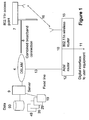
Figure 1 is a schematic illustration of the devices which co-operate to perform the method of the invention -
Figure 2 is a schematic illustration of an installation including several user terminations making use of a shared connection -
Figure 3 is a flow diagram illustrating the process of identifying the primary and secondary connections when a hub is first connected to the networks -
Figure 4 is a flow diagram illustrating the process of diversion of traffic from a routing by way of a primary connection to a routing by way of the secondary connection, on detection of a failure of the primary connection -
Figure 5 is a flow diagram illustrating the process of redirection of traffic from a routing by way of the secondary connection to resume a routing by way of the primary connection on detection of repair of the primary connection -
Figure 1 shows a network termination equipment 10 (hereinafter referred to as a "hub") capable of connection to one or more user devices, such as computers, over a digital interface 11 (wired or wireless). Thehub 10 has afirst connection 12 to anactive broadband circuit 13 connected to a DSLAM (Digital Subscriber Line Access Multiplexer ) 4, and aconcurrent standby circuit 15 that is made over aradio link 16 to alocal distribution point 7, such as an access point mounted on the top of a roadside pole. The access point is connected back to the DSLAM 4, via a dedicated fixed orradio circuit 8. -
Figure 2 shows theuser device 10, together with a number ofsimilar devices primary connection DSLAM 4. Each one is also capable of establishingwireless connection distribution point 7. As shown inFigure 1 , more than onesuch distribution point user hubs 16. 26, 36, 46 served by oneDSLAM 4. Thedistribution point 7 does not need to have sufficient capacity to handle all the associateduser terminals - The customer's
hub 10 normally uses thebroadband link 13 to connect to the internet/ISP, and periodically transmits "alive and well" messages via theradio connection 16 from thewireless access circuit 15 to thewireless distribution point 7 at the pole top. - The
hub 10 monitors correct function of thebroadband link 13 and thestandby connection 16. If thebroadband link 13 fails, it tests thestandby connectivity wireless access function 15 in the hub. Thewireless function 15 allows data to pass through to thewireless access point 7, and then to the DSLAM 4, putting into action the reserve broadband connection. This is used until the copper based connection is restored. - The user's terminal is connected to the
hub 10 by means of adigital connection 11. The hub routes this connection to either theprimary adsl connection 13 or, on failure of this, to thewireless connection 16. - As far as the rest of the network is concerned, the
ADSL router 12 and 802.11wireless router 15 are unrelated terminations. Data addressed to theadsl router 12 has to be diverted by the network, specifically theDSLAM 4, to reach thecustomer 10 via thewireless connection 16. In order to set up the alternative route, the network, specifically the DSLAM 4, needs to be configured to associate the tworoutings 13; 8 -16, and to set up the appropriatewireless route 8. This network control function is performed by aserver 9 associated with theDSLAM 4, in co-operation with theuser terminal 10. - The operation of the invention will now be described in more detail, with reference to
Figures 3 ,4 and5 . - As shown in
Figure 3 , when contact is first established between theDSLAM 4 and ahub 10, the DSLAM determines the geographical location of thenetwork termination 12. This may be accessed from adatabase 90 relating the topology of the fixed network to geographical location, and in particular to the locations ofdistribution points hub 10 and thenetwork server 9 associated with the DSLAM 4 because the network topology is known to the DSLAM, but the dual routing capability is a property of thehub 10. The process may be initiated by either thehub 10 or theserver 9. - In a preferred arrangement, the
hub 10, on connection to aDSLAM 4, transmits amessage 300 identifying itself as being configured for the dual routing capability. If the DSLAM has the facility for dual routing, the associatedserver 9 responds by accessing adatabase 90 with the network location of thenetwork termination 12 through which the hub has contacted the DSLAM 4 (step 301). Thedatabase 90 identifies adistribution point 7 that may be within wireless range of the location of thenetwork termination 12 and capable of providing the required backup service (step 302), and returns the identity of thisdistribution point 7 to the server 9 (step 303). Set-up instructions are then downloaded by theserver 9. - The download instructions may be transmitted to the
hub 10 over the already-established primary connection 13 (step 304). Thehub 10 then attempts to establish awireless link 16 between itswireless router 15 and the selected wireless distribution point 7 (step 305). The system may be configured to attempt connection between thehub 10 and more than onesuch distribution point - Alternatively, the download instructions may be sent over the
connection 8 to the selected wireless distribution point 7 (step 314), which initiates an attempt to establish awireless link 16 with thewireless router 15 in the hub 10 (step 315). (Again, in this variant, connection may be attempted by more than one wireless distribution point) - In either case, a
successful connection 16 is reported back to the server 9 (step 307, 317), over one of the two routings now available - not necessarily the one over which the download instructions were transmitted.. - Once a
suitable link 7 is identified, data relating to it is then stored by theDSLAM server 9 in astore 19 associated with the network termination 12 (step 308), and also by thehub 10, in order to allow connection to be made in case of failure of themain link 13. Eachnetwork termination respective store server 9. - As shown in
Figure 4 , during normal operation,traffic 400 is carried over the fixedline connection 13. Periodically, the hub transmits "alive and well"messages 309 over thewireless connection 16 to ensure that the reserve connection is available when required. In the event of a loss of this connection, the procedure described above with reference toFigure 3 is resumed in order to identify a new backup routing. - The
hub 10 periodically generates an "alive-and-well"message 401 for transmission over the fixedlink 13, similar to themessage 309 transmitted over the wireless link. The network-embeddedserver 9 receives these "alive-and-well" messages and uses them to maintain therecord 19 associated with the circuit 13 (step 402). - Should the
network server 9 fail to detect thismessage 401, indicating afailure 411 on the primary connection 13 (step 403), it retrieves data relating to thesecond path 8 from the database 19 (step 404), and is updated to release the primary path 13 (step 405) and transmit instructions (406) for thehub 10 to perform an IP refresh (407) using the IP address of thesecondary circuit 15 to cause allfuture information 408 generated by or for theuser terminal 10 to be transmitted over thesecond path access point 7. - Whilst the
backup routing 16 is in use, theuser hub 10 continues to attempt to transmit "alive and well"messages 401 over theprimary path 13, and theserver 9 continues to monitor theDSLAM 4 to determine whether these messages are being received, indicating that the link has been restored. On receipt of such amessage 401, the server initiates alink restoration process 501, updating theterminal data 19, instructing theDSLAM 4 to redirect incoming traffic destined for theuser hub 10 to the primary link 13 (step 505), and transmitting aninstruction 506 to theuser hub 10 to redirect outgoing traffic to the ADSL router 12 (step 507), thereby restoring service onto theprimary route 13 and releasing and re-establishing the IP address used by the user'shub 10. - "Alive and well" error messages may also be generated by the server for detection at the hub, so that it can initiate the transitions between the primary and secondary routings. A degradation, of either the alive and well message or the complete data transfer, less than complete loss of connection, may be alerted to the user so that the resilience option may be invoked proactively.
- In a preferred embodiment the
secondary path 8 is able to be shared between several users' termination points. This requires thenetwork server 9 to be able to support several user accounts and to poll, in turn, eachhub 10 associated with an account and IP address. If any hub detects a primary link failure, then it would report this as part of its alive and well message "as a failure of the primary path" and initiate connection on the wireless path. In the event of contention, allocation may be on a first-come-first-served basis, allocating bandwidth only to the first user, or the first few users, until all the available bandwidth is in use. Alternatively, at times of high contention, thewireless connection 8 may be delivered at a slower rate than for theprimary service 13, allowing several virtual services to be provided at any time. - The pole
top access point 7 may be dedicated to a restricted set of user hubs, specifically to provide the service resilience, or it may be a part of a public access network, theuser hub terminal 10 being allocated both a fixed-line broadband account on theADSL router side 13 and a wireless access account for use on thewireless router side 16. Software on thehub 10 would firstly detect a failedfixed link 13 and could then look for an alternate path by setting up a transmission path across thewireless link 16 to the poletop access point 7, using inbuilt account information. The IP address would then be released at theserver 9 and restored via thewireless link link 13 the hub would detect the restored connection, would close down the wireless connection, and restore service to the primary route. The IP address would be released and restored to the primary link.
Claims (19)
- A telecommunications network having provision for communications addressed to a given user device to be routed to a primary network address, means for associating a secondary network address with the primary network address, monitoring means for detecting a failure of communication with the user device at the primary address, and means for diverting connection to the secondary address when such failure is detected.
- A telecommunications network according to claim 1, wherein the monitoring means comprises means to detect the presence or absence of a signal transmitted by the user device from the primary address, and for diversion of the communication in the absence of such a signal.
- A telecommunications network according to claim 1 or claim 2, wherein the monitoring means includes means to detect resumption of communication with the primary address, and means for re-establishing connection through the primary address when the monitoring means detects that such connection has been restored.
- A telecommunications network according to claim 1, 2 or 3, comprising data storage means to record network topology information, means to detect the connection of a user device to the network by means of the primary address, means to determine, from the identity of the connection associated with he primary address and the network topology information stored in the data storage means, a second network address to which the user device may be connected, and means to transmit to the user device and/or the second connection point instructions to establish such a connection.
- A telecommunications network according to claim 1, claim 2, claim 3, or claim 4 wherein the primary connection is a dedicated fixed line connection and the secondary connection is a wireless connection.
- A telecommunications network according to claim 5 wherein the secondary connection is provided by a wireless distribution point associated with a plurality of fixed line terminations.
- A telecommunications network termination device having user device connection means for connection to one or more computing devices, first network connection means for connection to a network by way of a primary connection having a first network address, secondary network connection means for connection to a network by means of a second connection having a second network address, means for communicating with a network by means of the first connection means, monitoring means for identifying a failure of communication with the network by the first connection means, and means for diverting connection to the secondary connection means when such failure is detected.
- Telecommunications network termination device according to claim 7, further comprising monitoring means for identifying resumption of communication with the network from the primary address, and means for re-establishing connection through the primary address when the monitoring means detects that such connection has been restored.
- Telecommunications network termination device according to claim 7 or claim 8, further comprising monitoring means for determining the operating condition of the secondary route to ensure that it is working and intact.
- Telecommunications network termination device according to claim 7, claim 8, or claim 9, wherein the monitoring means comprises means to generate a connection integrity message for transmission by way of the connection, and having means to respond to diversion instructions received from the network.
- Telecommunications network termination device according to claim 7, claim 8, claim 9 or claim 10, comprising means for generating a signal on connection to a first connection indicative of its capability of connection by way of an alternative connection, and means for receiving instructions, over the first connection or a second connection, for establishing a backup connection between the user terminal and the network server over the said second connection.
- Telecommunications network termination device according to claim 7, claim 8, claim 9, claim 10 or claim 11, in which the primary connection means is for connection to a fixed line connection and the secondary connection means is for a wireless connection.
- A method of operating a telecommunications system in which connection between a user termination and a network may be made by means of a primary routing having a first network address and an alternative, secondary routing, having a second network address, wherein a monitoring signal is transmitted from the user terminal to a network control system over the primary routing and, if the monitoring signal is not detected by the network control system, the network control system causes traffic to and from the user terminal to be diverted over the secondary routing using the second network address.
- A method according to claim 13, wherein attempts to continue transmission of the monitoring signal over the primary routing whilst traffic is diverted over the secondary routing, and if the monitoring signal transmitted over the primary routing is again detected by the network control system, indicating that such connection has been restored, traffic is redirected over the primary network using the first network address.
- A method according to claim 13 or claim 14, wherein the operating condition of the secondary route is monitored to ensure that it is working and intact.
- A method according to claim 13, claim 14, or claim 15, wherein the user termination transmits connection integrity messages over the connection, and the network control system transmits diversion instructions to the user termination in the event that the connection integrity messages fail to be detected.
- A method according to claim 13, 14, 15 or 16, wherein on initial connection being established between a user termination and a first connection, a signal indicative of its capability of connection by way of an alternative connection is transmitted over the first connection, and on receiving this signal the network control system retrieves, from an associated store of network topology data, network address data relating to at least one secondary connection point, and transmits instructions, over the first connection or the second connection, for identifying a backup connection over the said second connection between the user terminal and the network control system, using the second network address.
- A method according to claim 13, claim 14, claim 15, claim 16, or claim 17, in which the primary connection is a fixed line connection and the secondary connection is a wireless connection.
- A method according to claim 18 wherein the secondary connection is provided by a wireless distribution point associated with a plurality of fixed line terminations.
Priority Applications (4)
| Application Number | Priority Date | Filing Date | Title |
|---|---|---|---|
| EP07252168A EP1995918A1 (en) | 2007-05-25 | 2007-05-25 | Alternative route selection in Telecommunications networks |
| PCT/GB2008/001229 WO2008145948A1 (en) | 2007-05-25 | 2008-04-07 | Alternative route selection in telecommunications networks |
| US12/600,395 US8514730B2 (en) | 2007-05-25 | 2008-04-07 | Telecommunications routing |
| EP08719004.7A EP2153592B1 (en) | 2007-05-25 | 2008-04-07 | Alternative route selection in telecommunications networks |
Applications Claiming Priority (1)
| Application Number | Priority Date | Filing Date | Title |
|---|---|---|---|
| EP07252168A EP1995918A1 (en) | 2007-05-25 | 2007-05-25 | Alternative route selection in Telecommunications networks |
Publications (1)
| Publication Number | Publication Date |
|---|---|
| EP1995918A1 true EP1995918A1 (en) | 2008-11-26 |
Family
ID=38196568
Family Applications (2)
| Application Number | Title | Priority Date | Filing Date |
|---|---|---|---|
| EP07252168A Ceased EP1995918A1 (en) | 2007-05-25 | 2007-05-25 | Alternative route selection in Telecommunications networks |
| EP08719004.7A Active EP2153592B1 (en) | 2007-05-25 | 2008-04-07 | Alternative route selection in telecommunications networks |
Family Applications After (1)
| Application Number | Title | Priority Date | Filing Date |
|---|---|---|---|
| EP08719004.7A Active EP2153592B1 (en) | 2007-05-25 | 2008-04-07 | Alternative route selection in telecommunications networks |
Country Status (3)
| Country | Link |
|---|---|
| US (1) | US8514730B2 (en) |
| EP (2) | EP1995918A1 (en) |
| WO (1) | WO2008145948A1 (en) |
Cited By (4)
| Publication number | Priority date | Publication date | Assignee | Title |
|---|---|---|---|---|
| EP2234335A1 (en) * | 2009-03-26 | 2010-09-29 | Societé Française du Radiotéléphone | Method for transmitting a self-diagnosis request from a multi-service box to a server of a high-speed network |
| WO2014083447A1 (en) * | 2012-11-28 | 2014-06-05 | Telefonaktiebolaget L M Ericsson (Publ) | Method and apparatus for facilitating process restart in an is-is system |
| KR20140080516A (en) * | 2011-09-26 | 2014-06-30 | 테라노스, 인코포레이티드 | Network connectivity methods and systems |
| US9596156B2 (en) | 2011-09-26 | 2017-03-14 | Theranos, Inc. | Network connectivity methods and systems |
Families Citing this family (7)
| Publication number | Priority date | Publication date | Assignee | Title |
|---|---|---|---|---|
| FR2966000A1 (en) * | 2010-10-11 | 2012-04-13 | France Telecom | LOCATION OF AN EQUIPMENT BY ITS IP ADDRESS. |
| US9148336B2 (en) * | 2012-11-19 | 2015-09-29 | International Business Machines Corporation | Resilient routing based on a multi-channel model for emergency management |
| US10003525B2 (en) * | 2014-11-14 | 2018-06-19 | Fisher-Rosemount Systems, Inc. | Methods and apparatus to provide redundancy in a process control system |
| US11238225B2 (en) | 2015-01-16 | 2022-02-01 | Hewlett-Packard Development Company, L.P. | Reading difficulty level based resource recommendation |
| CN112737946B (en) * | 2019-10-14 | 2023-09-05 | 中兴通讯股份有限公司 | Route advertising method, device, storage medium and system for IPv6 network |
| TWI763173B (en) * | 2020-12-14 | 2022-05-01 | 宏碁通信股份有限公司 | Internet of things system and backup channel utilization method thereof |
| CN114157561B (en) * | 2022-02-07 | 2022-07-15 | 阿里云计算有限公司 | Fault processing system and method |
Citations (3)
| Publication number | Priority date | Publication date | Assignee | Title |
|---|---|---|---|---|
| US6144641A (en) * | 1996-10-31 | 2000-11-07 | Kapcom Industries | Multi-protocol telecommunications routing optimization |
| US20030031180A1 (en) * | 1999-12-31 | 2003-02-13 | Ragula Systems D/B/A/ Fatpipe Networks | Combining routers to increase concurrency and redundancy in external network access |
| US20050008017A1 (en) * | 2000-12-29 | 2005-01-13 | Ragula Systems D/B/A Fatpipe Networks | Tools and techniques for directing packets over disparate networks |
Family Cites Families (2)
| Publication number | Priority date | Publication date | Assignee | Title |
|---|---|---|---|---|
| US7409451B1 (en) * | 2003-05-30 | 2008-08-05 | Aol Llc, A Delaware Limited Liability Company | Switching between connectivity types to maintain connectivity |
| US7590055B2 (en) * | 2004-02-09 | 2009-09-15 | Alcatel Lucent | High availability broadband connections through switching from wireline to diverse wireless network |
-
2007
- 2007-05-25 EP EP07252168A patent/EP1995918A1/en not_active Ceased
-
2008
- 2008-04-07 WO PCT/GB2008/001229 patent/WO2008145948A1/en active Application Filing
- 2008-04-07 US US12/600,395 patent/US8514730B2/en active Active
- 2008-04-07 EP EP08719004.7A patent/EP2153592B1/en active Active
Patent Citations (3)
| Publication number | Priority date | Publication date | Assignee | Title |
|---|---|---|---|---|
| US6144641A (en) * | 1996-10-31 | 2000-11-07 | Kapcom Industries | Multi-protocol telecommunications routing optimization |
| US20030031180A1 (en) * | 1999-12-31 | 2003-02-13 | Ragula Systems D/B/A/ Fatpipe Networks | Combining routers to increase concurrency and redundancy in external network access |
| US20050008017A1 (en) * | 2000-12-29 | 2005-01-13 | Ragula Systems D/B/A Fatpipe Networks | Tools and techniques for directing packets over disparate networks |
Cited By (13)
| Publication number | Priority date | Publication date | Assignee | Title |
|---|---|---|---|---|
| EP2234335A1 (en) * | 2009-03-26 | 2010-09-29 | Societé Française du Radiotéléphone | Method for transmitting a self-diagnosis request from a multi-service box to a server of a high-speed network |
| FR2943872A1 (en) * | 2009-03-26 | 2010-10-01 | Radiotelephone Sfr | METHOD FOR TRANSMITTING A SELF-DIAGNOSTIC REQUEST FROM A MULTISERVICE HOUSING TO A SERVER OF A HIGH-SPEED NETWORK AND HOUSING USING SUCH A METHOD |
| US9596156B2 (en) | 2011-09-26 | 2017-03-14 | Theranos, Inc. | Network connectivity methods and systems |
| KR20140080516A (en) * | 2011-09-26 | 2014-06-30 | 테라노스, 인코포레이티드 | Network connectivity methods and systems |
| CN103959272A (en) * | 2011-09-26 | 2014-07-30 | 赛拉诺斯股份有限公司 | Network connectivity methods and systems |
| EP2761488A4 (en) * | 2011-09-26 | 2015-09-02 | Theranos Inc | Network connectivity methods and systems |
| EP3142017A1 (en) * | 2011-09-26 | 2017-03-15 | Theranos, Inc. | Network connectivity methods and systems |
| CN103959272B (en) * | 2011-09-26 | 2018-11-16 | 赛拉诺斯知识产权有限责任公司 | Method for connecting network and system |
| EP3483735A1 (en) * | 2011-09-26 | 2019-05-15 | Theranos IP Company, LLC | Network connectivity methods and systems |
| US10425304B2 (en) | 2011-09-26 | 2019-09-24 | Theranos Ip Company, Llc | Methods and systems for network connectivity |
| US10541896B2 (en) | 2011-09-26 | 2020-01-21 | Theranos Ip Company, Llc | Network connectivity methods and systems |
| US11323345B2 (en) | 2011-09-26 | 2022-05-03 | Labrador Diagnostics Llc | Methods and systems for network connectivity |
| WO2014083447A1 (en) * | 2012-11-28 | 2014-06-05 | Telefonaktiebolaget L M Ericsson (Publ) | Method and apparatus for facilitating process restart in an is-is system |
Also Published As
| Publication number | Publication date |
|---|---|
| WO2008145948A1 (en) | 2008-12-04 |
| US20100150012A1 (en) | 2010-06-17 |
| US8514730B2 (en) | 2013-08-20 |
| EP2153592A1 (en) | 2010-02-17 |
| EP2153592B1 (en) | 2016-04-27 |
Similar Documents
| Publication | Publication Date | Title |
|---|---|---|
| EP2153592B1 (en) | Alternative route selection in telecommunications networks | |
| US5182744A (en) | Telecommunications network restoration architecture | |
| US6553025B1 (en) | Multiple routing and automatic network detection of a monitored call from an intercepted targeted IP phone to multiple monitoring locations | |
| EP2926599B1 (en) | Restoration of network access | |
| US8441924B2 (en) | Redundant capability in a fiber optic network | |
| US8976949B2 (en) | Central call platform | |
| US5796718A (en) | Method of and system for intelligent access line protect switching | |
| JP2005012812A (en) | Distributed protection switching | |
| WO2002098085A9 (en) | Internet communication system | |
| US7953210B2 (en) | Switch proxy for providing emergency stand-alone service in remote access systems | |
| US6072793A (en) | Electronically controlled main distributing frame | |
| US6208856B1 (en) | Method for maintaining service nodes in a telecommunications network | |
| JP2002300275A (en) | Mobile communication system, gate exchange selection server and gate exchange selection method | |
| CN101227437A (en) | Equipment, system and method for implementing media gateway resource share | |
| AU2007201412B2 (en) | Address notification in network system and address notifying method | |
| US6717939B1 (en) | Virtual transport server in a telecommunication network | |
| CN101656798A (en) | Rerouting of trunks by a PBX to an alternate PBX | |
| JP6236488B2 (en) | Station side optical line termination device, redundant device switching method, and redundant device switching program | |
| US20200351196A1 (en) | Failover system | |
| US8233381B1 (en) | VoIP telephone system with distributed account codes | |
| US6614901B1 (en) | Method and system for a scaleable virtual switch | |
| KR102168583B1 (en) | Load balancing management apparatus and control method thereof | |
| CN115622869A (en) | Data processing method, device, equipment, storage medium and system | |
| US20120127987A1 (en) | PACKET ROUTE MANAGEMENT DEVICE, VoIP SYSTEM AND METHOD OF CONTROLLING VoIP VOICE CALL QUALITY | |
| JPH06350644A (en) | Call redirection function service system in non-operation of station accommodating called subscriber |
Legal Events
| Date | Code | Title | Description |
|---|---|---|---|
| PUAI | Public reference made under article 153(3) epc to a published international application that has entered the european phase |
Free format text: ORIGINAL CODE: 0009012 |
|
| AK | Designated contracting states |
Kind code of ref document: A1 Designated state(s): AT BE BG CH CY CZ DE DK EE ES FI FR GB GR HU IE IS IT LI LT LU LV MC MT NL PL PT RO SE SI SK TR |
|
| AX | Request for extension of the european patent |
Extension state: AL BA HR MK RS |
|
| STAA | Information on the status of an ep patent application or granted ep patent |
Free format text: STATUS: THE APPLICATION HAS BEEN REFUSED |
|
| 18R | Application refused |
Effective date: 20081210 |