EP1995879A1 - Base station and transmission method - Google Patents
Base station and transmission method Download PDFInfo
- Publication number
- EP1995879A1 EP1995879A1 EP07290656A EP07290656A EP1995879A1 EP 1995879 A1 EP1995879 A1 EP 1995879A1 EP 07290656 A EP07290656 A EP 07290656A EP 07290656 A EP07290656 A EP 07290656A EP 1995879 A1 EP1995879 A1 EP 1995879A1
- Authority
- EP
- European Patent Office
- Prior art keywords
- transmitter
- gsm
- band
- tuning
- transmission method
- Prior art date
- Legal status (The legal status is an assumption and is not a legal conclusion. Google has not performed a legal analysis and makes no representation as to the accuracy of the status listed.)
- Granted
Links
- 238000000034 method Methods 0.000 title claims abstract description 35
- 230000005540 biological transmission Effects 0.000 title claims abstract description 17
- 230000008878 coupling Effects 0.000 claims 1
- 238000010168 coupling process Methods 0.000 claims 1
- 238000005859 coupling reaction Methods 0.000 claims 1
- 230000008569 process Effects 0.000 description 6
- 238000005259 measurement Methods 0.000 description 4
- 230000008901 benefit Effects 0.000 description 3
- 230000009467 reduction Effects 0.000 description 3
- 238000010586 diagram Methods 0.000 description 2
- 238000001228 spectrum Methods 0.000 description 2
- 239000000969 carrier Substances 0.000 description 1
- 230000008859 change Effects 0.000 description 1
- 230000006872 improvement Effects 0.000 description 1
- 230000005405 multipole Effects 0.000 description 1
Images

Classifications
-
- H—ELECTRICITY
- H04—ELECTRIC COMMUNICATION TECHNIQUE
- H04B—TRANSMISSION
- H04B1/00—Details of transmission systems, not covered by a single one of groups H04B3/00 - H04B13/00; Details of transmission systems not characterised by the medium used for transmission
- H04B1/02—Transmitters
- H04B1/04—Circuits
- H04B1/0483—Transmitters with multiple parallel paths
-
- H—ELECTRICITY
- H04—ELECTRIC COMMUNICATION TECHNIQUE
- H04B—TRANSMISSION
- H04B1/00—Details of transmission systems, not covered by a single one of groups H04B3/00 - H04B13/00; Details of transmission systems not characterised by the medium used for transmission
- H04B1/005—Details of transmission systems, not covered by a single one of groups H04B3/00 - H04B13/00; Details of transmission systems not characterised by the medium used for transmission adapting radio receivers, transmitters andtransceivers for operation on two or more bands, i.e. frequency ranges
- H04B1/0053—Details of transmission systems, not covered by a single one of groups H04B3/00 - H04B13/00; Details of transmission systems not characterised by the medium used for transmission adapting radio receivers, transmitters andtransceivers for operation on two or more bands, i.e. frequency ranges with common antenna for more than one band
- H04B1/0057—Details of transmission systems, not covered by a single one of groups H04B3/00 - H04B13/00; Details of transmission systems not characterised by the medium used for transmission adapting radio receivers, transmitters andtransceivers for operation on two or more bands, i.e. frequency ranges with common antenna for more than one band using diplexing or multiplexing filters for selecting the desired band
-
- H—ELECTRICITY
- H04—ELECTRIC COMMUNICATION TECHNIQUE
- H04W—WIRELESS COMMUNICATION NETWORKS
- H04W88/00—Devices specially adapted for wireless communication networks, e.g. terminals, base stations or access point devices
- H04W88/08—Access point devices
- H04W88/10—Access point devices adapted for operation in multiple networks, e.g. multi-mode access points
Definitions
- the present invention relates to the field of base stations, in particular to multi-standard base stations such as GSM/UMTS base stations. Furthermore, the present invention relates to a transmission method combining signals from two transmitters of such a base station.
- the spectrum range for the GSM900 operation is between 890 MHz and 915 MHz for uplink operation and between 935 MHz and 960 MHz for downlink operation. Furthermore, the spectrum range for the EGSM service is between 880 MHz and 910 MHz for uplink operation and between 925 MHz and 960 MHz for downlink operation. Since the cell range of UMTS900 is comparable to that of GSM900 and EGSM, the main savings for the operators would be to use the existing GSM900/EGSM antennas and feeders also for UMTS/LTE900. For each antenna there is usually a filter-duplexer which separates between transmit and receive band, so that there is one transmit path for each antenna.
- each transmitter can be directly connected to said duplexer.
- Such configuration has a relatively low loss.
- hybrid combiners which are also known as wideband combiners, are used to combine two signals from two transmitters.
- Such a combiner is wideband, i.e. not frequency selective, and has a principle loss of (n-1)/n where n is the number of inputs to combine.
- Such combiners are used for a sector with two GSM transmitters and one UMTS/LTE transmitter, so that either the two GSM transmitters or one GSM transmitter and the UMTS/LTE transmitter are combined. If the same coverage, i.e. the same output power, is required as before the addition of the UMTS/LTE transmitter, new GSM transmitters with two times the output power must be used.
- said transmitters must be high power transmitters or the principle of "concentric cells" is used. That is, far away mobiles are allocated to the GSM transmitter without combiner and the other transmitter is used for mobiles with better radio conditions.
- filter combiners are used for splitting between the frequencies used for the two signals, wherein said filter combiners can be either tunable or fixed.
- the term tunable refers to the operation which can be done in the field.
- Tunable filters are usually single pole filters.
- Multipole filters are usually called fixed filters, since they require complex tuning procedures and measurement equipment and a lot of experience for the tuning process. The number of poles determines how much "gap" band is needed between several filter inputs. For single pole filters, this gap is at least as large as the pass band bandwidth.
- the filters must be tailored to the frequencies used on the site. That is, changing frequency allocation requires the replacement of the filters. Furthermore, the filters are site specific and customer specific. Therefore, there are probably long ordering times and complex logistics. A further disadvantage of such solution is that the filters are costly.
- a tuned filter combiner can be used.
- the GSM transmitters are combined with the filter combiner on one antenna, and the other antenna is used for UMTS/LTE. This works well as long as GSM frequency hopping is not used.
- due to the tuned filter it is not possible to use the quite attractive generalized frequency hopping, that is a frequency hopping where the BCCH transmitter is not hopping at all and the other transmitter uses hopping over many frequencies.
- a band-pass filter and a notch filter are used to combine the signals from two transmitters, wherein both filters are tuned to the same frequency.
- the present invention provides a transmission approach for multi-standard base stations.
- such multi-standard base station is a GSM/UMTS base station comprising at least one GSM transmitter and at least one UMTS/LTE transmitter.
- the band-pass filter is used for the GSM BCCH carrier and the notch filter is intended for either a potentially hopping GSM carrier or a UMTS/LTE carrier.
- a first path of the combining means contains a tunable notch filter for a frequency hopping GSM carrier or a WCDMA signal and a second path contains a tunable band-pass filter for a frequency fixed GSM BCCH carrier. After combining the filter outputs the combined signal is adapted to be transmitted through an antenna of the multi-standard base station.
- the proposed combining principle for two GSM carriers or one GSM carrier and one UMTS carrier gives a significant improvement of the transmitted power level.
- an operator of a BTS system has a better range coverage or signal respectively data quality, since the present invention provides an increased RF output power of a multi-standard base station and therefore offers a possibility to increase the transmitted RF level without raising the power output of a transmitter amplifier.
- the combining principle according to the present invention offers low losses of approximately 0,8 dB or even lower both on the band-pass path and the notch path. In particular, these low losses do not cause significant coverage reduction.
- the combination of band-pass filter and notch filter is used instead of the wideband combiner and can be easily implemented in existing BTS systems.
- manual tuning filters can be used.
- the hopping transmitter is configured to send on the BCCH frequency and the notch filter is tuned manually to have the minimum output power after the filter.
- the hopping transmitter is switched off and the BCCH transmitter is activated.
- the band-pass filter is tuned to get the maximum output power after the filter. This process needs probably two or three cycles.
- manual tuning requires a site visit each time the frequency plan of the operator changes.
- the band-pass and notch filters are remotely tuned. More preferably the remote tuning is performed automatically. Contrary to manual tuning, site visits can be avoided when the filters are remotely tuned. Furthermore, tuning motors, processors and other necessary equipment is not too expensive, so that cost reduction is achieved by remote tuning. By automatically tuning the filters a further cost reduction is achieved. Automatic tuning means consist for example of motorized filters, selective receivers and a processor.
- Tuning methods of band-pass filters are known and can comprise the following steps. At first the desired band-pass frequency and a factory table are used to calculate a rough tuning position for each frequency. Then, fine tuning is done, for example, by maximizing the output power while varying the tuning around the calculated rough tuning position. Furthermore, this can be done by searching the upper and lower-n dB points and taking the middle position between these points. In addition, the signal phase can be observed for fine tuning. Preferably the tuning process is only carried out if the module gets RF power. In this manner wrong tunings and unnecessary actions are avoided.
- tuning of a notch filter is provided, which is part of a base station.
- Tuning of the notch filter can be carried out in two ways. According to a first way the notch filter is mechanically coupled to the band-pass filter so that the automatic tuning of the band-pass filter will automatically tune the notch filter. There is no requirement on the presence of signals on the notch input. This method requires a good mechanical matching over the full tuning range, temperature, and lifetime of the module comprising both the band-pass filter and the notch filter.
- the notch is tuned separately from the band-pass.
- Rough tuning can use a factory table as for the band-pass, wherein fine tuning can be carried out by several methods.
- a process as described for the manual tuning is used. This method has the advantage that only one measurement point is needed, but can not be done during normal operation. That is, retuning would require a traffic interruption.
- This first method is particularly useful if the mechanical stability is good enough to avoid any retuning except in case of a frequency change.
- a frequency selective power measurement at the connection of the notch filter to the transmitter is used. Additionally, the phase can be measured. The measurement is done on the frequency of the other transmitter and the tuning process minimizes the feed through power of the other transmitter.
- the power at the band-pass filter connection to the load is measured at the other transmitter frequency and the tuning process tries to maximize this power, if the notch is build by using a band-pass filter and a circulator.
- a further advantage of the present invention is that there is no need for a high power UMTS transmitter and that the present invention provides for lower power consumption and dissipation.
- the present invention provides for a low loss transmission method combining signals from two transmitters.
- FIG. 1 shows a block diagram of a multi-standard base station 1 according to the present invention.
- Said base station has at least two transmitters 2, 3 and the RF signal power delivered by each of the transmitters is fed into a module 4.
- said module 4 comprises a band-pass filter 5 and a notch filter 6.
- the transmitter 2 outputs a hopping GSM signal or a WCDMA signal and the further transmitter 3 outputs a GSM BCCH signal.
- the GSM BCCH signal passes the band-pass filter 5 and the hopping GSM signal or the WCDMA signal is fed through the notch path comprising the notch filter 6 to the output port.
- said module 4 comprising the combination of a band-pass filter 5 and a notch filter 6 can be easily integrated therein.
- Said module 4 acts as a combiner having two inputs and one output wherein at least one of the inputs is adapted to receive a GSM signal and the further input may receive a hopping GSM signal or a WCDMA signal.
- the combiner 4 basically consists of a notch path and a band-pass path comprising the notch filter 6 and the band-pass filter 5, respectively.
- said module 4 is adapted to combine two GSM signals or one GSM and one WCDMA signal to one output.
- the module output is fed to an appropriate means 7 for adapting the combined output signal to be transmitted through an antenna 8 of the multi-standard base station 1.
- Figure 2 shows the multi-standard base station of figure 1 further comprising a controller 9.
- the controller 9 is adapted to tune the band-pass filter 5 and the notch filter 6 to the same frequency, which is essential with respect to the present invention.
- said controller 9 can tune said filters 5, 6 to a desired center frequency by means of an integrated processor (not shown).
- a tuning trigger signal can be input into the controller 9.
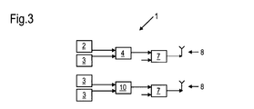
- FIG. 3 shows a further embodiment of a multi-standard base station 1 according to the present invention.
- Said base station comprises two antennas 8, three narrow band transmitters 3, and one wide band transmitter 2.
- such configuration allows one low loss connection for the UMTS transmitter 2, one low loss connection for a GSM transmitter 3, and two higher loss connections for further GSM transmitters 3.
- the upper part of the multi-standard base station of figure 3 corresponds to the multi-standard base station 1 explained with respect to figure 1 .
- the lower part of the base station 1 of figure 3 consists of two GSM transmitters 3, a wideband combiner 10, a means 7 for adapting the output of the combiner 10, and an antenna 8 for transmitting the combined signal output of the combiner 10.
- the configuration according to figure 3 can be used with a so called "concentric cell" behavior for GSM.
- the low loss GSM transmitter 2 is used for the broadcast carrier and for mobiles with high path loss and the other mobiles can use any GSM transmitter 3.
Landscapes
- Engineering & Computer Science (AREA)
- Computer Networks & Wireless Communication (AREA)
- Signal Processing (AREA)
- Transmitters (AREA)
- Mobile Radio Communication Systems (AREA)
- Steroid Compounds (AREA)
Abstract
Description
- The present invention relates to the field of base stations, in particular to multi-standard base stations such as GSM/UMTS base stations. Furthermore, the present invention relates to a transmission method combining signals from two transmitters of such a base station.
- With the introduction of UMTS and LTE, which is intended to replace UMTS, the main interest of GSM network operators is to minimize the introduction cost while keeping a high flexibility for future changes and while keeping the GSM performance more or less unchanged.
- The spectrum range for the GSM900 operation is between 890 MHz and 915 MHz for uplink operation and between 935 MHz and 960 MHz for downlink operation. Furthermore, the spectrum range for the EGSM service is between 880 MHz and 910 MHz for uplink operation and between 925 MHz and 960 MHz for downlink operation. Since the cell range of UMTS900 is comparable to that of GSM900 and EGSM, the main savings for the operators would be to use the existing GSM900/EGSM antennas and feeders also for UMTS/LTE900. For each antenna there is usually a filter-duplexer which separates between transmit and receive band, so that there is one transmit path for each antenna. As long as the number of transmitters is less than or equal to the number of transmit paths (antennas), each transmitter can be directly connected to said duplexer. In usual sites, there are two antennas per sector and so GSM stations with up to two transmitters per sector allow direct connection. Such configuration has a relatively low loss.
- However, if it is required to add a UMTS/LTE transmitter to a GSM base station (BTS) which has already two transmitters, the main question is how the transmitters could be combined. In order to combine the signals of two transmitters, two different methods are known.
- In a first method hybrid combiners, which are also known as wideband combiners, are used to combine two signals from two transmitters. Such a combiner is wideband, i.e. not frequency selective, and has a principle loss of (n-1)/n where n is the number of inputs to combine. Such combiners are used for a sector with two GSM transmitters and one UMTS/LTE transmitter, so that either the two GSM transmitters or one GSM transmitter and the UMTS/LTE transmitter are combined. If the same coverage, i.e. the same output power, is required as before the addition of the UMTS/LTE transmitter, new GSM transmitters with two times the output power must be used. Furthermore, if one GSM transmitter and one UMTS/LTE transmitter are combined, said transmitters must be high power transmitters or the principle of "concentric cells" is used. That is, far away mobiles are allocated to the GSM transmitter without combiner and the other transmitter is used for mobiles with better radio conditions.
- In a further method filter combiners are used for splitting between the frequencies used for the two signals, wherein said filter combiners can be either tunable or fixed. The term tunable refers to the operation which can be done in the field. Tunable filters are usually single pole filters. Multipole filters are usually called fixed filters, since they require complex tuning procedures and measurement equipment and a lot of experience for the tuning process. The number of poles determines how much "gap" band is needed between several filter inputs. For single pole filters, this gap is at least as large as the pass band bandwidth. Even though the approach of splitting between the frequencies used for the two signals provides the benefit that the GSM and UMTS transmitters have a low loss, said approach has significant disadvantages. The filters must be tailored to the frequencies used on the site. That is, changing frequency allocation requires the replacement of the filters. Furthermore, the filters are site specific and customer specific. Therefore, there are probably long ordering times and complex logistics. A further disadvantage of such solution is that the filters are costly.
- In case where no combining is used, but all antennas are already in use, a tuned filter combiner can be used. The GSM transmitters are combined with the filter combiner on one antenna, and the other antenna is used for UMTS/LTE. This works well as long as GSM frequency hopping is not used. However, due to the tuned filter it is not possible to use the quite attractive generalized frequency hopping, that is a frequency hopping where the BCCH transmitter is not hopping at all and the other transmitter uses hopping over many frequencies.
- Connecting one GSM transmitter to one antenna and using a tuned combiner for combining the other GSM transmitter and the UMTS/LTE transmitter has the disadvantage that due to the gap band required for it, which is at least 5 MHz for a 5 MHz UMTS signal, a big part of the GSM band is unusable. Operators usually own 12,5 MHz which is one half of the 25 MHz band. Having 5 MHz for UMTS plus 5 MHz gap leaves nearly no room for GSM, which makes this solution impossible.
- It is an object of the present invention to provide a transmission method combining two signals from two transmitters with relatively low loss and a multi-standard base station for carrying out said transmission method.
- According to the present invention a band-pass filter and a notch filter are used to combine the signals from two transmitters, wherein both filters are tuned to the same frequency. In particular, the present invention provides a transmission approach for multi-standard base stations. Preferably, such multi-standard base station is a GSM/UMTS base station comprising at least one GSM transmitter and at least one UMTS/LTE transmitter. In said GSM/UMTS base station the band-pass filter is used for the GSM BCCH carrier and the notch filter is intended for either a potentially hopping GSM carrier or a UMTS/LTE carrier. That is, a first path of the combining means contains a tunable notch filter for a frequency hopping GSM carrier or a WCDMA signal and a second path contains a tunable band-pass filter for a frequency fixed GSM BCCH carrier. After combining the filter outputs the combined signal is adapted to be transmitted through an antenna of the multi-standard base station.
- The proposed combining principle for two GSM carriers or one GSM carrier and one UMTS carrier gives a significant improvement of the transmitted power level. Thus, an operator of a BTS system has a better range coverage or signal respectively data quality, since the present invention provides an increased RF output power of a multi-standard base station and therefore offers a possibility to increase the transmitted RF level without raising the power output of a transmitter amplifier. Furthermore, the combining principle according to the present invention offers low losses of approximately 0,8 dB or even lower both on the band-pass path and the notch path. In particular, these low losses do not cause significant coverage reduction. With respect to the above-mentioned prior art solutions the combination of band-pass filter and notch filter is used instead of the wideband combiner and can be easily implemented in existing BTS systems.
- With respect to tuning of the filters different methods can be used. In principle, manual tuning filters can be used. During commissioning of the base station the filters are manually tuned in the following manner. The hopping transmitter is configured to send on the BCCH frequency and the notch filter is tuned manually to have the minimum output power after the filter. The hopping transmitter is switched off and the BCCH transmitter is activated. The band-pass filter is tuned to get the maximum output power after the filter. This process needs probably two or three cycles. However, manual tuning requires a site visit each time the frequency plan of the operator changes.
- In a preferred embodiment of the present invention the band-pass and notch filters are remotely tuned. More preferably the remote tuning is performed automatically. Contrary to manual tuning, site visits can be avoided when the filters are remotely tuned. Furthermore, tuning motors, processors and other necessary equipment is not too expensive, so that cost reduction is achieved by remote tuning. By automatically tuning the filters a further cost reduction is achieved. Automatic tuning means consist for example of motorized filters, selective receivers and a processor.
- Tuning methods of band-pass filters are known and can comprise the following steps. At first the desired band-pass frequency and a factory table are used to calculate a rough tuning position for each frequency. Then, fine tuning is done, for example, by maximizing the output power while varying the tuning around the calculated rough tuning position. Furthermore, this can be done by searching the upper and lower-n dB points and taking the middle position between these points. In addition, the signal phase can be observed for fine tuning. Preferably the tuning process is only carried out if the module gets RF power. In this manner wrong tunings and unnecessary actions are avoided.
- According to the present invention tuning of a notch filter is provided, which is part of a base station. Tuning of the notch filter can be carried out in two ways. According to a first way the notch filter is mechanically coupled to the band-pass filter so that the automatic tuning of the band-pass filter will automatically tune the notch filter. There is no requirement on the presence of signals on the notch input. This method requires a good mechanical matching over the full tuning range, temperature, and lifetime of the module comprising both the band-pass filter and the notch filter.
- Alternatively, the notch is tuned separately from the band-pass. Rough tuning can use a factory table as for the band-pass, wherein fine tuning can be carried out by several methods. According to a first method a process as described for the manual tuning is used. This method has the advantage that only one measurement point is needed, but can not be done during normal operation. That is, retuning would require a traffic interruption. This first method is particularly useful if the mechanical stability is good enough to avoid any retuning except in case of a frequency change.
- According to a further method a frequency selective power measurement at the connection of the notch filter to the transmitter is used. Additionally, the phase can be measured. The measurement is done on the frequency of the other transmitter and the tuning process minimizes the feed through power of the other transmitter.
- According to a still further method the power at the band-pass filter connection to the load is measured at the other transmitter frequency and the tuning process tries to maximize this power, if the notch is build by using a band-pass filter and a circulator.
- Even though a notch filter and a band-pass filter must be integrated in a multi-standard base station to carry out the present invention, existing GSM transmitters can be kept in said base station. A further advantage of the present invention is that there is no need for a high power UMTS transmitter and that the present invention provides for lower power consumption and dissipation. In particular, the present invention provides for a low loss transmission method combining signals from two transmitters.
- These and other aspects of the invention will be apparent from and elucidated with reference to the embodiments thereafter. It should be noted that the use of reference signs shall not be construed as limiting the scope of the invention.
-
- Figure 1
- shows a block diagram of a multi-standard base station according to the present invention;
- Figure 2
- shows the multi-standard base station of
figure 1 further comprising a controller; and - Figure 3
- shows a base station with three narrow band transmitters and one wide band transmitter.
-
Figure 1 shows a block diagram of amulti-standard base station 1 according to the present invention. Said base station has at least twotransmitters module 4. According to the present invention saidmodule 4 comprises a band-pass filter 5 and anotch filter 6. In the case of a GSM/UMTS base station thetransmitter 2 outputs a hopping GSM signal or a WCDMA signal and thefurther transmitter 3 outputs a GSM BCCH signal. The GSM BCCH signal passes the band-pass filter 5 and the hopping GSM signal or the WCDMA signal is fed through the notch path comprising thenotch filter 6 to the output port. - When expanding a GSM base station to be used as
multi-standard base station 1 saidmodule 4 comprising the combination of a band-pass filter 5 and anotch filter 6 can be easily integrated therein. Saidmodule 4 acts as a combiner having two inputs and one output wherein at least one of the inputs is adapted to receive a GSM signal and the further input may receive a hopping GSM signal or a WCDMA signal. Thus, thecombiner 4 basically consists of a notch path and a band-pass path comprising thenotch filter 6 and the band-pass filter 5, respectively. In particular, saidmodule 4 is adapted to combine two GSM signals or one GSM and one WCDMA signal to one output. - After the outputs of the band-
pass filter 5 and thenotch filter 6 are combined within themodule 4, the module output is fed to anappropriate means 7 for adapting the combined output signal to be transmitted through anantenna 8 of themulti-standard base station 1. -
Figure 2 shows the multi-standard base station offigure 1 further comprising acontroller 9. In particular, thecontroller 9 is adapted to tune the band-pass filter 5 and thenotch filter 6 to the same frequency, which is essential with respect to the present invention. For example, saidcontroller 9 can tune saidfilters controller 9. When tuning the band-pass and the notch branches in parallel it is assumed that both branches have the same mechanical, thermal and electrical behavior. -
Figure 3 shows a further embodiment of amulti-standard base station 1 according to the present invention. Said base station comprises twoantennas 8, threenarrow band transmitters 3, and onewide band transmitter 2. In the case of a GSM/UMTS base station 1 such configuration allows one low loss connection for theUMTS transmitter 2, one low loss connection for aGSM transmitter 3, and two higher loss connections forfurther GSM transmitters 3. The upper part of the multi-standard base station offigure 3 corresponds to themulti-standard base station 1 explained with respect tofigure 1 . The lower part of thebase station 1 offigure 3 consists of twoGSM transmitters 3, awideband combiner 10, ameans 7 for adapting the output of thecombiner 10, and anantenna 8 for transmitting the combined signal output of thecombiner 10. The configuration according tofigure 3 can be used with a so called "concentric cell" behavior for GSM. The lowloss GSM transmitter 2 is used for the broadcast carrier and for mobiles with high path loss and the other mobiles can use anyGSM transmitter 3. -
- 1
- base station
- 2
- transmitter
- 3
- transmitter
- 4
- module
- 5
- band-pass filter
- 6
- notch filter
- 7
- means for adapting a combined output
- 8
- antenna
- 9
- controller
- 10
- wideband combiner
Claims (8)
- Transmission method combining signals from two transmitters, the method comprising the steps of:- providing the signal of a first transmitter (3) to a band-pass filter (5),- providing the signal of a second transmitter (2) to a notch filter (6),- tuning the band-pass filter (5) and the notch filter (6) to the same frequency, and- combining the outputs of the band-pass filter (5) and the notch filter (6).
- The transmission method according to claim 1, further comprising the step of providing the combined output signal to means (7) adapting said combined output signal for transmission through an antenna (8).
- The transmission method according to claim 1, wherein the first transmitter (3) is a GSM transmitter and the respective signal is a GSM BCCH carrier, wherein the second transmitter (2) is a GSM transmitter and the respective signal is a hopping GSM carrier, and wherein the GSM BCCH carrier is provided to the band-pass filter (5) and the hopping GSM carrier is provided to the notch filter (6).
- The transmission method according to claim 1, wherein the first transmitter is a GSM transmitter and the respective signal is a GSM BCCH carrier, wherein the second transmitter is a UMTS/LTE transmitter and the respective signal is a UMTS/LTE carrier, and wherein the GSM BCCH carrier is provided to the band-pass filter (5) and the UMTS/LTE carrier is provided to the notch filter (6).
- The transmission method according to claim 1, wherein the tuning step is performed by automatic tuning means (9).
- The transmission method according to claim 1, wherein the tuning step is done by mechanically coupling the notch filter (6) to the band-pass filter (5).
- The transmission method according to claim 1, wherein the tuning step is done by separately tuning the band-pass filter (5) and the notch filter (6).
- Base station comprising at least first and second transmitters and means for carrying out the transmission method according to one of claim 1.
Priority Applications (3)
| Application Number | Priority Date | Filing Date | Title |
|---|---|---|---|
| AT07290656T ATE437478T1 (en) | 2007-05-22 | 2007-05-22 | BASE STATION AND TRANSMISSION METHOD |
| DE602007001682T DE602007001682D1 (en) | 2007-05-22 | 2007-05-22 | Base station and transmission method |
| EP07290656A EP1995879B1 (en) | 2007-05-22 | 2007-05-22 | Base station and transmission method |
Applications Claiming Priority (1)
| Application Number | Priority Date | Filing Date | Title |
|---|---|---|---|
| EP07290656A EP1995879B1 (en) | 2007-05-22 | 2007-05-22 | Base station and transmission method |
Publications (2)
| Publication Number | Publication Date |
|---|---|
| EP1995879A1 true EP1995879A1 (en) | 2008-11-26 |
| EP1995879B1 EP1995879B1 (en) | 2009-07-22 |
Family
ID=38330699
Family Applications (1)
| Application Number | Title | Priority Date | Filing Date |
|---|---|---|---|
| EP07290656A Not-in-force EP1995879B1 (en) | 2007-05-22 | 2007-05-22 | Base station and transmission method |
Country Status (3)
| Country | Link |
|---|---|
| EP (1) | EP1995879B1 (en) |
| AT (1) | ATE437478T1 (en) |
| DE (1) | DE602007001682D1 (en) |
Cited By (3)
| Publication number | Priority date | Publication date | Assignee | Title |
|---|---|---|---|---|
| WO2010040823A1 (en) * | 2008-10-09 | 2010-04-15 | St Ericsson Sa | Shared rf front-end module for cellular application |
| WO2010072178A1 (en) * | 2008-12-26 | 2010-07-01 | 大唐移动通信设备有限公司 | Transmitting and receiving method for carrier aggregation multi-carrier system and data transmission device |
| EP3468062A1 (en) * | 2017-10-05 | 2019-04-10 | Nokia Technologies Oy | Heterogeneously equipped multi antenna system and method of operating such system |
Citations (3)
| Publication number | Priority date | Publication date | Assignee | Title |
|---|---|---|---|---|
| US20040048634A1 (en) * | 2001-09-14 | 2004-03-11 | Yuki Satoh | High-frequency composite switch module |
| EP1418680A1 (en) * | 2001-08-10 | 2004-05-12 | Hitachi Metals, Ltd. | Bypass filter; multi;band antenna switch circuit; and layered module composite part and communication device using them |
| US20050221769A1 (en) * | 1999-03-18 | 2005-10-06 | Hitachi Metals, Ltd. | High-frequency switch circuit |
-
2007
- 2007-05-22 EP EP07290656A patent/EP1995879B1/en not_active Not-in-force
- 2007-05-22 AT AT07290656T patent/ATE437478T1/en not_active IP Right Cessation
- 2007-05-22 DE DE602007001682T patent/DE602007001682D1/en active Active
Patent Citations (3)
| Publication number | Priority date | Publication date | Assignee | Title |
|---|---|---|---|---|
| US20050221769A1 (en) * | 1999-03-18 | 2005-10-06 | Hitachi Metals, Ltd. | High-frequency switch circuit |
| EP1418680A1 (en) * | 2001-08-10 | 2004-05-12 | Hitachi Metals, Ltd. | Bypass filter; multi;band antenna switch circuit; and layered module composite part and communication device using them |
| US20040048634A1 (en) * | 2001-09-14 | 2004-03-11 | Yuki Satoh | High-frequency composite switch module |
Cited By (7)
| Publication number | Priority date | Publication date | Assignee | Title |
|---|---|---|---|---|
| WO2010040823A1 (en) * | 2008-10-09 | 2010-04-15 | St Ericsson Sa | Shared rf front-end module for cellular application |
| WO2010072178A1 (en) * | 2008-12-26 | 2010-07-01 | 大唐移动通信设备有限公司 | Transmitting and receiving method for carrier aggregation multi-carrier system and data transmission device |
| EP3468062A1 (en) * | 2017-10-05 | 2019-04-10 | Nokia Technologies Oy | Heterogeneously equipped multi antenna system and method of operating such system |
| CN109639326A (en) * | 2017-10-05 | 2019-04-16 | 诺基亚技术有限公司 | The multiaerial system that isomery is equipped with and the method for operating this system |
| JP2019071606A (en) * | 2017-10-05 | 2019-05-09 | ノキア テクノロジーズ オーワイ | Heterogeneous multi-antenna system and method for operating the system |
| CN109639326B (en) * | 2017-10-05 | 2022-08-23 | 诺基亚技术有限公司 | Heterogeneous equipped multi-antenna system and method of operating such a system |
| US11546037B2 (en) | 2017-10-05 | 2023-01-03 | Nokia Technologies Oy | Heterogeneously equipped multi antenna system and method of operating such system |
Also Published As
| Publication number | Publication date |
|---|---|
| EP1995879B1 (en) | 2009-07-22 |
| DE602007001682D1 (en) | 2009-09-03 |
| ATE437478T1 (en) | 2009-08-15 |
Similar Documents
| Publication | Publication Date | Title |
|---|---|---|
| US9154171B2 (en) | Reconfigurable radio frequency circuits and methods of receiving | |
| EP2159933B1 (en) | Levelling amplifiers in a distributed antenna system | |
| US9356697B2 (en) | Distributed antenna system and method | |
| US9306669B2 (en) | Optic distributed antenna system supporting multi-band multi-carrier service over a reduced number of optic core lines | |
| US8504111B2 (en) | Active electrical tilt antenna apparatus with distributed amplifier | |
| US10141985B2 (en) | Determining actual loop gain in a distributed antenna system (DAS) | |
| KR101803342B1 (en) | Apparatus and method for a multiband radio operating in a wireless network | |
| US20110092171A1 (en) | Signal combiner | |
| US20140370824A1 (en) | Methods and apparatus for antenna tuning | |
| CN105490714B (en) | The multicarrier sending and receiving method of terminal, terminal | |
| US20180069741A1 (en) | Module for combining signals having different frequencies | |
| EP1995879B1 (en) | Base station and transmission method | |
| CN104639216B (en) | A kind of electrical tilt antenna | |
| KR101909283B1 (en) | Combiner and multi-band base station system using the combiner | |
| US11601145B2 (en) | Tunable antenna and communications terminal | |
| EP2733976A1 (en) | System, device, and method for transmitting multi-input-multi-output signals | |
| US8099133B2 (en) | Apparatus and a method for directing a received signal in an antenna system | |
| KR101554005B1 (en) | Feeder Cable Sharing Apparatus for Multiband Combine and Antena Tilting at Multiband BTS System | |
| HK40036013B (en) | Adjustable antenna and communication terminal | |
| HK40036013A (en) | Adjustable antenna and communication terminal |
Legal Events
| Date | Code | Title | Description |
|---|---|---|---|
| PUAI | Public reference made under article 153(3) epc to a published international application that has entered the european phase |
Free format text: ORIGINAL CODE: 0009012 |
|
| 17P | Request for examination filed |
Effective date: 20071023 |
|
| AK | Designated contracting states |
Kind code of ref document: A1 Designated state(s): AT BE BG CH CY CZ DE DK EE ES FI FR GB GR HU IE IS IT LI LT LU LV MC MT NL PL PT RO SE SI SK TR |
|
| AX | Request for extension of the european patent |
Extension state: AL BA HR MK RS |
|
| GRAP | Despatch of communication of intention to grant a patent |
Free format text: ORIGINAL CODE: EPIDOSNIGR1 |
|
| GRAS | Grant fee paid |
Free format text: ORIGINAL CODE: EPIDOSNIGR3 |
|
| GRAA | (expected) grant |
Free format text: ORIGINAL CODE: 0009210 |
|
| AK | Designated contracting states |
Kind code of ref document: B1 Designated state(s): AT BE BG CH CY CZ DE DK EE ES FI FR GB GR HU IE IS IT LI LT LU LV MC MT NL PL PT RO SE SI SK TR |
|
| REG | Reference to a national code |
Ref country code: GB Ref legal event code: FG4D |
|
| AKX | Designation fees paid |
Designated state(s): AT BE BG CH CY CZ DE DK EE ES FI FR GB GR HU IE IS IT LI LT LU LV MC MT NL PL PT RO SE SI SK TR |
|
| REG | Reference to a national code |
Ref country code: CH Ref legal event code: EP |
|
| REG | Reference to a national code |
Ref country code: IE Ref legal event code: FG4D |
|
| REF | Corresponds to: |
Ref document number: 602007001682 Country of ref document: DE Date of ref document: 20090903 Kind code of ref document: P |
|
| NLV1 | Nl: lapsed or annulled due to failure to fulfill the requirements of art. 29p and 29m of the patents act | ||
| PG25 | Lapsed in a contracting state [announced via postgrant information from national office to epo] |
Ref country code: LT Free format text: LAPSE BECAUSE OF FAILURE TO SUBMIT A TRANSLATION OF THE DESCRIPTION OR TO PAY THE FEE WITHIN THE PRESCRIBED TIME-LIMIT Effective date: 20090722 Ref country code: SE Free format text: LAPSE BECAUSE OF FAILURE TO SUBMIT A TRANSLATION OF THE DESCRIPTION OR TO PAY THE FEE WITHIN THE PRESCRIBED TIME-LIMIT Effective date: 20090722 Ref country code: AT Free format text: LAPSE BECAUSE OF FAILURE TO SUBMIT A TRANSLATION OF THE DESCRIPTION OR TO PAY THE FEE WITHIN THE PRESCRIBED TIME-LIMIT Effective date: 20090722 Ref country code: ES Free format text: LAPSE BECAUSE OF FAILURE TO SUBMIT A TRANSLATION OF THE DESCRIPTION OR TO PAY THE FEE WITHIN THE PRESCRIBED TIME-LIMIT Effective date: 20091102 Ref country code: IS Free format text: LAPSE BECAUSE OF FAILURE TO SUBMIT A TRANSLATION OF THE DESCRIPTION OR TO PAY THE FEE WITHIN THE PRESCRIBED TIME-LIMIT Effective date: 20091122 Ref country code: FI Free format text: LAPSE BECAUSE OF FAILURE TO SUBMIT A TRANSLATION OF THE DESCRIPTION OR TO PAY THE FEE WITHIN THE PRESCRIBED TIME-LIMIT Effective date: 20090722 |
|
| PG25 | Lapsed in a contracting state [announced via postgrant information from national office to epo] |
Ref country code: NL Free format text: LAPSE BECAUSE OF FAILURE TO SUBMIT A TRANSLATION OF THE DESCRIPTION OR TO PAY THE FEE WITHIN THE PRESCRIBED TIME-LIMIT Effective date: 20090722 Ref country code: LV Free format text: LAPSE BECAUSE OF FAILURE TO SUBMIT A TRANSLATION OF THE DESCRIPTION OR TO PAY THE FEE WITHIN THE PRESCRIBED TIME-LIMIT Effective date: 20090722 Ref country code: PL Free format text: LAPSE BECAUSE OF FAILURE TO SUBMIT A TRANSLATION OF THE DESCRIPTION OR TO PAY THE FEE WITHIN THE PRESCRIBED TIME-LIMIT Effective date: 20090722 Ref country code: SI Free format text: LAPSE BECAUSE OF FAILURE TO SUBMIT A TRANSLATION OF THE DESCRIPTION OR TO PAY THE FEE WITHIN THE PRESCRIBED TIME-LIMIT Effective date: 20090722 |
|
| PG25 | Lapsed in a contracting state [announced via postgrant information from national office to epo] |
Ref country code: BG Free format text: LAPSE BECAUSE OF FAILURE TO SUBMIT A TRANSLATION OF THE DESCRIPTION OR TO PAY THE FEE WITHIN THE PRESCRIBED TIME-LIMIT Effective date: 20091022 Ref country code: PT Free format text: LAPSE BECAUSE OF FAILURE TO SUBMIT A TRANSLATION OF THE DESCRIPTION OR TO PAY THE FEE WITHIN THE PRESCRIBED TIME-LIMIT Effective date: 20091122 |
|
| PG25 | Lapsed in a contracting state [announced via postgrant information from national office to epo] |
Ref country code: EE Free format text: LAPSE BECAUSE OF FAILURE TO SUBMIT A TRANSLATION OF THE DESCRIPTION OR TO PAY THE FEE WITHIN THE PRESCRIBED TIME-LIMIT Effective date: 20090722 Ref country code: RO Free format text: LAPSE BECAUSE OF FAILURE TO SUBMIT A TRANSLATION OF THE DESCRIPTION OR TO PAY THE FEE WITHIN THE PRESCRIBED TIME-LIMIT Effective date: 20090722 Ref country code: CZ Free format text: LAPSE BECAUSE OF FAILURE TO SUBMIT A TRANSLATION OF THE DESCRIPTION OR TO PAY THE FEE WITHIN THE PRESCRIBED TIME-LIMIT Effective date: 20090722 Ref country code: DK Free format text: LAPSE BECAUSE OF FAILURE TO SUBMIT A TRANSLATION OF THE DESCRIPTION OR TO PAY THE FEE WITHIN THE PRESCRIBED TIME-LIMIT Effective date: 20090722 |
|
| PLBE | No opposition filed within time limit |
Free format text: ORIGINAL CODE: 0009261 |
|
| STAA | Information on the status of an ep patent application or granted ep patent |
Free format text: STATUS: NO OPPOSITION FILED WITHIN TIME LIMIT |
|
| PG25 | Lapsed in a contracting state [announced via postgrant information from national office to epo] |
Ref country code: SK Free format text: LAPSE BECAUSE OF FAILURE TO SUBMIT A TRANSLATION OF THE DESCRIPTION OR TO PAY THE FEE WITHIN THE PRESCRIBED TIME-LIMIT Effective date: 20090722 Ref country code: BE Free format text: LAPSE BECAUSE OF FAILURE TO SUBMIT A TRANSLATION OF THE DESCRIPTION OR TO PAY THE FEE WITHIN THE PRESCRIBED TIME-LIMIT Effective date: 20090722 |
|
| 26N | No opposition filed |
Effective date: 20100423 |
|
| PG25 | Lapsed in a contracting state [announced via postgrant information from national office to epo] |
Ref country code: GR Free format text: LAPSE BECAUSE OF FAILURE TO SUBMIT A TRANSLATION OF THE DESCRIPTION OR TO PAY THE FEE WITHIN THE PRESCRIBED TIME-LIMIT Effective date: 20091023 |
|
| PG25 | Lapsed in a contracting state [announced via postgrant information from national office to epo] |
Ref country code: MC Free format text: LAPSE BECAUSE OF NON-PAYMENT OF DUE FEES Effective date: 20100531 |
|
| PG25 | Lapsed in a contracting state [announced via postgrant information from national office to epo] |
Ref country code: IT Free format text: LAPSE BECAUSE OF FAILURE TO SUBMIT A TRANSLATION OF THE DESCRIPTION OR TO PAY THE FEE WITHIN THE PRESCRIBED TIME-LIMIT Effective date: 20090722 |
|
| PG25 | Lapsed in a contracting state [announced via postgrant information from national office to epo] |
Ref country code: IE Free format text: LAPSE BECAUSE OF NON-PAYMENT OF DUE FEES Effective date: 20100522 Ref country code: MT Free format text: LAPSE BECAUSE OF FAILURE TO SUBMIT A TRANSLATION OF THE DESCRIPTION OR TO PAY THE FEE WITHIN THE PRESCRIBED TIME-LIMIT Effective date: 20090722 |
|
| REG | Reference to a national code |
Ref country code: CH Ref legal event code: PL |
|
| PG25 | Lapsed in a contracting state [announced via postgrant information from national office to epo] |
Ref country code: LI Free format text: LAPSE BECAUSE OF NON-PAYMENT OF DUE FEES Effective date: 20110531 Ref country code: CH Free format text: LAPSE BECAUSE OF NON-PAYMENT OF DUE FEES Effective date: 20110531 |
|
| PG25 | Lapsed in a contracting state [announced via postgrant information from national office to epo] |
Ref country code: CY Free format text: LAPSE BECAUSE OF FAILURE TO SUBMIT A TRANSLATION OF THE DESCRIPTION OR TO PAY THE FEE WITHIN THE PRESCRIBED TIME-LIMIT Effective date: 20090722 |
|
| PG25 | Lapsed in a contracting state [announced via postgrant information from national office to epo] |
Ref country code: HU Free format text: LAPSE BECAUSE OF FAILURE TO SUBMIT A TRANSLATION OF THE DESCRIPTION OR TO PAY THE FEE WITHIN THE PRESCRIBED TIME-LIMIT Effective date: 20100123 Ref country code: LU Free format text: LAPSE BECAUSE OF NON-PAYMENT OF DUE FEES Effective date: 20100522 |
|
| PG25 | Lapsed in a contracting state [announced via postgrant information from national office to epo] |
Ref country code: TR Free format text: LAPSE BECAUSE OF FAILURE TO SUBMIT A TRANSLATION OF THE DESCRIPTION OR TO PAY THE FEE WITHIN THE PRESCRIBED TIME-LIMIT Effective date: 20090722 |
|
| REG | Reference to a national code |
Ref country code: FR Ref legal event code: GC Effective date: 20131018 |
|
| REG | Reference to a national code |
Ref country code: FR Ref legal event code: RG Effective date: 20141016 |
|
| REG | Reference to a national code |
Ref country code: FR Ref legal event code: PLFP Year of fee payment: 9 |
|
| REG | Reference to a national code |
Ref country code: FR Ref legal event code: CA Effective date: 20150521 |
|
| REG | Reference to a national code |
Ref country code: FR Ref legal event code: CA Effective date: 20150521 |
|
| REG | Reference to a national code |
Ref country code: FR Ref legal event code: PLFP Year of fee payment: 10 |
|
| PGFP | Annual fee paid to national office [announced via postgrant information from national office to epo] |
Ref country code: DE Payment date: 20160520 Year of fee payment: 10 Ref country code: GB Payment date: 20160520 Year of fee payment: 10 |
|
| PGFP | Annual fee paid to national office [announced via postgrant information from national office to epo] |
Ref country code: FR Payment date: 20160520 Year of fee payment: 10 |
|
| REG | Reference to a national code |
Ref country code: DE Ref legal event code: R119 Ref document number: 602007001682 Country of ref document: DE |
|
| GBPC | Gb: european patent ceased through non-payment of renewal fee |
Effective date: 20170522 |
|
| REG | Reference to a national code |
Ref country code: FR Ref legal event code: ST Effective date: 20180131 |
|
| PG25 | Lapsed in a contracting state [announced via postgrant information from national office to epo] |
Ref country code: DE Free format text: LAPSE BECAUSE OF NON-PAYMENT OF DUE FEES Effective date: 20171201 Ref country code: GB Free format text: LAPSE BECAUSE OF NON-PAYMENT OF DUE FEES Effective date: 20170522 |
|
| PG25 | Lapsed in a contracting state [announced via postgrant information from national office to epo] |
Ref country code: FR Free format text: LAPSE BECAUSE OF NON-PAYMENT OF DUE FEES Effective date: 20170531 |