EP1995853A1 - Electric Motor - Google Patents
Electric Motor Download PDFInfo
- Publication number
- EP1995853A1 EP1995853A1 EP07301063A EP07301063A EP1995853A1 EP 1995853 A1 EP1995853 A1 EP 1995853A1 EP 07301063 A EP07301063 A EP 07301063A EP 07301063 A EP07301063 A EP 07301063A EP 1995853 A1 EP1995853 A1 EP 1995853A1
- Authority
- EP
- European Patent Office
- Prior art keywords
- housing
- bearings
- motor
- rotor
- motor according
- Prior art date
- Legal status (The legal status is an assumption and is not a legal conclusion. Google has not performed a legal analysis and makes no representation as to the accuracy of the status listed.)
- Withdrawn
Links
- 239000004065 semiconductor Substances 0.000 claims description 4
- 238000001816 cooling Methods 0.000 claims description 3
- 230000008901 benefit Effects 0.000 description 3
- 230000005226 mechanical processes and functions Effects 0.000 description 3
- 229920003023 plastic Polymers 0.000 description 3
- 239000004033 plastic Substances 0.000 description 3
- 230000005484 gravity Effects 0.000 description 1
- 238000012544 monitoring process Methods 0.000 description 1
Images
Classifications
-
- H—ELECTRICITY
- H02—GENERATION; CONVERSION OR DISTRIBUTION OF ELECTRIC POWER
- H02K—DYNAMO-ELECTRIC MACHINES
- H02K5/00—Casings; Enclosures; Supports
- H02K5/04—Casings or enclosures characterised by the shape, form or construction thereof
- H02K5/16—Means for supporting bearings, e.g. insulating supports or means for fitting bearings in the bearing-shields
- H02K5/173—Means for supporting bearings, e.g. insulating supports or means for fitting bearings in the bearing-shields using bearings with rolling contact, e.g. ball bearings
- H02K5/1735—Means for supporting bearings, e.g. insulating supports or means for fitting bearings in the bearing-shields using bearings with rolling contact, e.g. ball bearings radially supporting the rotary shaft at only one end of the rotor
-
- H—ELECTRICITY
- H02—GENERATION; CONVERSION OR DISTRIBUTION OF ELECTRIC POWER
- H02K—DYNAMO-ELECTRIC MACHINES
- H02K11/00—Structural association of dynamo-electric machines with electric components or with devices for shielding, monitoring or protection
- H02K11/30—Structural association with control circuits or drive circuits
- H02K11/33—Drive circuits, e.g. power electronics
-
- H—ELECTRICITY
- H02—GENERATION; CONVERSION OR DISTRIBUTION OF ELECTRIC POWER
- H02K—DYNAMO-ELECTRIC MACHINES
- H02K2211/00—Specific aspects not provided for in the other groups of this subclass relating to measuring or protective devices or electric components
- H02K2211/03—Machines characterised by circuit boards, e.g. pcb
Definitions
- the invention relates to an electric motor according to the preamble of claim 1.
- the housing is normally of cylindrical shape and has two bearing shields at the ends. Often the bearing shields contain ball bearings as bearings.
- electric motors especially brushless electric motors, contain electronics elements including power electronics. They also include position sensors like a hall sensor cooperating with a sensor magnet fixed to the rotating part.
- Such motors are not easy to assemble:
- the axle hinders the electronic board.
- the bearing shields have to be screwed-on, as they are part of the mounting possibilities for assembling the motor to its load.
- the electronics is no longer accessible for service.
- the idea is to arrange both bearings at the same side of the rotating part.
- power electronic elements PE a printed circuit board PCB, and a sensor magnet SM.
- the rotor MR is built essentially out of permanent magnets, as usual.
- the stator St as usual consists of a number of coils wound on a body made out of a stack of stator sheets.
- stator and rotor In non-brushless electric motors the roles of stator and rotor with respect to permanent magnets and coils is inverted.
- the axle Ax is carrying the rotor and is carried by the two bearings BB.
- the axle Ax is leaving the housing for driving a load, here seen at the right hand side.
- the two bearings BB now both are on the same side of the rotor MR.
- the bearings are ball bearings, they have to have a certain distance from one another to be able to correctly bear the axle with the rotor.
- roller bearings may be no such distance is necessary; in principle than the rollers could be such broad to serve as two bearings.
- the end plate can be part of, and in this example is part of a housing part HP1, that also includes the cylindrical part for housing rotor MR and stator St.
- housing part HP2 At the other side there is a mere cover as housing part HP2, that does not have any mechanical function and thus does not need to be carefully screwed.
- axle Ax with the pre-assembled rotor MR can be inserted.
- stator St pre-assembled with the commutating electric parts and the electrical connection may be imposed on the rotor MR.
- power electronic parts get a close contact to the housing for cooling reasons.
- Mounting possibilities MP2 can be foreseen at the front side of the part carrying the bearings (bearing region) or, MP1, at the front side of the proper motor housing part, or both.
- the commutating electric parts in the case of brushless motors essentially consist of at least one sensor for sensing the actual angular position, and electronic parts, including power electronic elements PE, to activate the respective coils of the stator.
- sensors normally at least one Hall sensor is used in cooperation with at least one sensor magnet SM affixed to the rotor. In this case such magnet can be affixed at the front of the axle.
- the electronic parts and mostly also the sensor or sensors are assembled on a printed circuit board PCB, as also shown in the exemplary figure.
- the invention presents enough room and enough design freedom for adding more electronics on this printed circuit board PCB or even further planes of printed circuit boards for carrying more electronics.
- An actual trend to include further electronics into motors benefits therefrom.
- the second housing part HP2 does not have mechanical functions it can even be opened during operation of the motor to give access to the electronics for monitoring.
- the cover HP2 can be made out of plastics, maybe with a snap fit part for mounting on the first housing part HP1.
- the main housing part, housing part HP1 can be a simple and cheep cast part. If it is thermally sufficient, it could be made out of plastics.
- the power electronics PE needs to be cooled what can best be done in using a thermally conducting housing, especially a metallic diecast one.
- the power electronics, that is the power semiconductors, on the printed circuit board can be brought into close contact with the inner side of the housing for cooling reasons. Special bags may be foreseen in the housing for this task.
- first housing part HP1 could be made in two parts, a first one being cylindrical, as usual, and a second one being a separate bearing shield with an unconventional shape, here including both bearings.
Landscapes
- Engineering & Computer Science (AREA)
- Power Engineering (AREA)
- Microelectronics & Electronic Packaging (AREA)
- Motor Or Generator Frames (AREA)
Abstract
Description
- The invention relates to an electric motor according to the preamble of claim 1.
- Such electric motors are very well known in the art. The housing is normally of cylindrical shape and has two bearing shields at the ends. Often the bearing shields contain ball bearings as bearings. Nowadays electric motors, especially brushless electric motors, contain electronics elements including power electronics. They also include position sensors like a hall sensor cooperating with a sensor magnet fixed to the rotating part.
- Such motors are not easy to assemble: The axle hinders the electronic board. The bearing shields have to be screwed-on, as they are part of the mounting possibilities for assembling the motor to its load. The electronics is no longer accessible for service.
- It is the object of the invention to provide a motor that is easier to assemble.
- This object is achieved by an electric motor according to the teachings of claim 1.
- The idea is to arrange both bearings at the same side of the rotating part.
- Such arrangement has further advantages or offers the possibility to foresee further advantageous elements:
- Mounting possibilities can be foreseen in a plane between the bearings and the rotor, which leads to an operation with less vibration.
- The main part of the housing can be made as an inexpensive diecast part.
- A simple cover that has no mechanical function will close the motor. It could even be a snapped in part of plastics.
- When electronics elements are foreseen, there is more room and more freedom for their mechanical design, especially for printed circuit boards.
- Power electronic parts, that is power semiconductors, may be easily brought into close thermal contact with the housing, which then, of course, should be thermally conducting.
- Bags for the power semiconductors can easily be provided in the housing.
- Also the part of the housing that carries the bearings contributes to the heat transfer.
- The free end of the axle offers an easy way to affix a magnet for sensing the position.
- Further embodiments of the invention are to be found in the subclaims and in the description.
- In the following the invention will be described with the aid of the accompanying drawing:
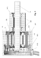
- Figure 1
- shows a longitudinal section through an electric motor according to the invention.
- Based on
figure 1 first the parts of any electric motor are described: We see a housing, HP1 and HP2, a rotor MR, a stator St, an axle Ax, and two bearings BB, here shown as ball bearings. - In addition we see, not necessarily part of or restricted to the invention, power electronic elements PE, a printed circuit board PCB, and a sensor magnet SM.
- The rotor MR is built essentially out of permanent magnets, as usual.
- The stator St as usual consists of a number of coils wound on a body made out of a stack of stator sheets.
- In non-brushless electric motors the roles of stator and rotor with respect to permanent magnets and coils is inverted.
- The axle Ax is carrying the rotor and is carried by the two bearings BB. The axle Ax is leaving the housing for driving a load, here seen at the right hand side.
- Different from what is usual, according to the invention the two bearings BB now both are on the same side of the rotor MR. In the shown example, where the bearings are ball bearings, they have to have a certain distance from one another to be able to correctly bear the axle with the rotor. In case of roller bearings may be no such distance is necessary; in principle than the rollers could be such broad to serve as two bearings.
- It is obvious that such arrangement anyway offers enough support to the axle and the rotor as the usual both-sided arrangement.
- The assembly of such type of motor is easily to achieve. There is no need to separately affix two bearing shields. At the side where the two bearings are, the end plate can be part of, and in this example is part of a housing part HP1, that also includes the cylindrical part for housing rotor MR and stator St. At the other side there is a mere cover as housing part HP2, that does not have any mechanical function and thus does not need to be carefully screwed.
- Then the axle Ax with the pre-assembled rotor MR can be inserted.
- Next the stator St pre-assembled with the commutating electric parts and the electrical connection may be imposed on the rotor MR. Here only care must be taken that power electronic parts get a close contact to the housing for cooling reasons.
- Finally the housing is being closed by the second housing part HP2, a mere cover.
- What cannot be seen in the figure is the mounting possibilities at the bearing-sided end. Normally for such task one has, and can have also here, a number of holes with internal screw threads. The fact that the bearings only need a housing part with less diameter compared to the housing part of the proper motor parts has an additional advantage: Mounting possibilities MP2 can be foreseen at the front side of the part carrying the bearings (bearing region) or, MP1, at the front side of the proper motor housing part, or both. When mounting the motor between the proper motor and the bearings using mounting possibilities MP1, we have the already mentioned situation with less vibration, because then the mounting is as near to the center of gravity as possible.
- The commutating electric parts in the case of brushless motors essentially consist of at least one sensor for sensing the actual angular position, and electronic parts, including power electronic elements PE, to activate the respective coils of the stator. As sensor in such situation normally at least one Hall sensor is used in cooperation with at least one sensor magnet SM affixed to the rotor. In this case such magnet can be affixed at the front of the axle.
- As usual in such situation, the electronic parts and mostly also the sensor or sensors are assembled on a printed circuit board PCB, as also shown in the exemplary figure. The invention presents enough room and enough design freedom for adding more electronics on this printed circuit board PCB or even further planes of printed circuit boards for carrying more electronics. An actual trend to include further electronics into motors benefits therefrom. As the second housing part HP2 does not have mechanical functions it can even be opened during operation of the motor to give access to the electronics for monitoring.
- If it is not necessary for shielding reasons, the cover HP2 can be made out of plastics, maybe with a snap fit part for mounting on the first housing part HP1.
- The main housing part, housing part HP1, can be a simple and cheep cast part. If it is thermally sufficient, it could be made out of plastics. Mostly the power electronics PE needs to be cooled what can best be done in using a thermally conducting housing, especially a metallic diecast one. There the power electronics, that is the power semiconductors, on the printed circuit board can be brought into close contact with the inner side of the housing for cooling reasons. Special bags may be foreseen in the housing for this task.
- Of course, the first housing part HP1 could be made in two parts, a first one being cylindrical, as usual, and a second one being a separate bearing shield with an unconventional shape, here including both bearings.
Claims (6)
- Electric motor with a housing (HP1, HP2), a rotor (MR), a stator (St), an axle (Ax), and two bearings (BB), characterized in, that both bearings (BB) are arranged at the same side of the rotor (MR).
- Motor according to claim 1, characterized in, that at the bearing-sided end mounting possibilities (MP1, MP2) is foreseen.
- Motor according to claim 1, characterized in, that the housing is built in two parts, such that one part (HP1) contains the proper motor and the bearing region and a second part (HP2) is designed as a cover at the side far from the bearings.
- Motor according to claim 1, characterized in, that at the side far from the bearings an electronic board (PCB) is placed.
- Motor according to claim 4, characterized in, that the housing (HP1) is thermally conducting and power semiconductors placed on the electronic board (PCB) are in contact with the inner side of the housing for cooling reasons.
- Motor according to claim 2, characterized in, that the housing part housing the bearings has less diameter than the housing part housing the proper motor, and that mounting possibilities (MP1) are foreseen at the front of the housing part housing the proper motor facing housing part housing the bearings.
Priority Applications (3)
| Application Number | Priority Date | Filing Date | Title |
|---|---|---|---|
| EP07301063A EP1995853A1 (en) | 2007-05-24 | 2007-05-24 | Electric Motor |
| US12/125,570 US20080290748A1 (en) | 2007-05-24 | 2008-05-22 | Electric motor |
| CNA2008101091572A CN101312312A (en) | 2007-05-24 | 2008-05-23 | Electric motor |
Applications Claiming Priority (1)
| Application Number | Priority Date | Filing Date | Title |
|---|---|---|---|
| EP07301063A EP1995853A1 (en) | 2007-05-24 | 2007-05-24 | Electric Motor |
Publications (1)
| Publication Number | Publication Date |
|---|---|
| EP1995853A1 true EP1995853A1 (en) | 2008-11-26 |
Family
ID=38594096
Family Applications (1)
| Application Number | Title | Priority Date | Filing Date |
|---|---|---|---|
| EP07301063A Withdrawn EP1995853A1 (en) | 2007-05-24 | 2007-05-24 | Electric Motor |
Country Status (3)
| Country | Link |
|---|---|
| US (1) | US20080290748A1 (en) |
| EP (1) | EP1995853A1 (en) |
| CN (1) | CN101312312A (en) |
Cited By (3)
| Publication number | Priority date | Publication date | Assignee | Title |
|---|---|---|---|---|
| US11437900B2 (en) | 2019-12-19 | 2022-09-06 | Black & Decker Inc. | Modular outer-rotor brushless motor for a power tool |
| US11757330B2 (en) | 2019-12-19 | 2023-09-12 | Black & Decker, Inc. | Canned outer-rotor brushless motor for a power tool |
| US12176794B2 (en) | 2021-11-19 | 2024-12-24 | Black & Decker Inc. | Outer-rotor brushless motor for a power tool |
Families Citing this family (5)
| Publication number | Priority date | Publication date | Assignee | Title |
|---|---|---|---|---|
| US7984704B1 (en) | 2010-04-21 | 2011-07-26 | Tier David H | Crankcase sidewall for supporting a crankshaft |
| DE102015203775A1 (en) * | 2015-03-03 | 2016-09-08 | Robert Bosch Gmbh | Drive device, in particular as part of a comfort drive in a motor vehicle |
| JP2016192832A (en) * | 2015-03-30 | 2016-11-10 | 日本電産株式会社 | motor |
| EP3403320B1 (en) * | 2016-01-13 | 2020-03-04 | Pierburg Pump Technology GmbH | Automotive electric fluidic pump |
| JPWO2017169033A1 (en) * | 2016-03-29 | 2018-11-22 | 三菱電機株式会社 | Electric blower and electric vacuum cleaner provided with the electric blower |
Citations (3)
| Publication number | Priority date | Publication date | Assignee | Title |
|---|---|---|---|---|
| US3753016A (en) * | 1972-03-17 | 1973-08-14 | Siemens Ag | Bearing system for shafts driven by an electric motor |
| US7015605B1 (en) * | 1998-11-05 | 2006-03-21 | Trw Automotive Electronics & Components Gmbh & Co. Kg | Electromotive drive system for use with a pump of a power-assisted steering system in a motor vehicle |
| US20060267432A1 (en) * | 2005-05-31 | 2006-11-30 | Archer William A | Electric motor that provides motor length reduction |
Family Cites Families (4)
| Publication number | Priority date | Publication date | Assignee | Title |
|---|---|---|---|---|
| JP3357074B2 (en) * | 1996-08-09 | 2002-12-16 | ケーニツヒ ウント バウエル アクチエンゲゼルシヤフト | Torso drive |
| JP3730889B2 (en) * | 2001-08-20 | 2006-01-05 | 日信工業株式会社 | Motor for pump operation |
| JP4904894B2 (en) * | 2005-04-21 | 2012-03-28 | 日本電産株式会社 | Axial fan |
| DE102006025487A1 (en) * | 2005-06-07 | 2006-12-14 | Alstom Technology Ltd. | Dynamo-electric machine e.g. generator, has brushless exciter cooled through gaseous cooling medium e.g. air, by using cooling circuit, and one separate fan for circulation of cooling medium in cooling circuit of exciter |
-
2007
- 2007-05-24 EP EP07301063A patent/EP1995853A1/en not_active Withdrawn
-
2008
- 2008-05-22 US US12/125,570 patent/US20080290748A1/en not_active Abandoned
- 2008-05-23 CN CNA2008101091572A patent/CN101312312A/en active Pending
Patent Citations (3)
| Publication number | Priority date | Publication date | Assignee | Title |
|---|---|---|---|---|
| US3753016A (en) * | 1972-03-17 | 1973-08-14 | Siemens Ag | Bearing system for shafts driven by an electric motor |
| US7015605B1 (en) * | 1998-11-05 | 2006-03-21 | Trw Automotive Electronics & Components Gmbh & Co. Kg | Electromotive drive system for use with a pump of a power-assisted steering system in a motor vehicle |
| US20060267432A1 (en) * | 2005-05-31 | 2006-11-30 | Archer William A | Electric motor that provides motor length reduction |
Cited By (4)
| Publication number | Priority date | Publication date | Assignee | Title |
|---|---|---|---|---|
| US11437900B2 (en) | 2019-12-19 | 2022-09-06 | Black & Decker Inc. | Modular outer-rotor brushless motor for a power tool |
| US11757330B2 (en) | 2019-12-19 | 2023-09-12 | Black & Decker, Inc. | Canned outer-rotor brushless motor for a power tool |
| US12218567B2 (en) | 2019-12-19 | 2025-02-04 | Black & Decker Inc. | Power tool having an outer-rotor brushless motor |
| US12176794B2 (en) | 2021-11-19 | 2024-12-24 | Black & Decker Inc. | Outer-rotor brushless motor for a power tool |
Also Published As
| Publication number | Publication date |
|---|---|
| CN101312312A (en) | 2008-11-26 |
| US20080290748A1 (en) | 2008-11-27 |
Similar Documents
| Publication | Publication Date | Title |
|---|---|---|
| EP1995853A1 (en) | Electric Motor | |
| JP5528329B2 (en) | Control device-integrated electric power steering apparatus motor and electric power steering apparatus | |
| EP1627459B1 (en) | Brushless motor | |
| US7294944B2 (en) | Brushless motor | |
| EP3046237B1 (en) | Ceiling fan motor | |
| JP5957713B2 (en) | motor | |
| CN103459236B (en) | Drive Unit Integrated Rotating Motor | |
| EP2068427B1 (en) | Inner rotor brushless motor | |
| US9622349B2 (en) | Control device, and motor unit including control device | |
| JP2009521196A5 (en) | ||
| CN105981267A (en) | Electric motor with retainer and assembly method thereof | |
| JP7432706B2 (en) | Brushless DC electric motor for automotive wiper system | |
| JP2015012782A (en) | Motor | |
| CN113273054A (en) | Motor | |
| JP2020165409A (en) | Electric pump device and electric pump device mounting structure | |
| JP2020165408A (en) | Electric pump device and electric pump device mounting structure | |
| JP5940276B2 (en) | motor | |
| US20080024023A1 (en) | Fan for vehicle and its motor | |
| CN112954893B (en) | Printed circuit board assembly, control electronics and electric motor drive unit | |
| JP2012170265A (en) | Fan motor | |
| KR100660305B1 (en) | Brushless DC Motor | |
| JP2020165410A (en) | Electric pump device and electric pump device mounting structure | |
| JP2008141881A (en) | Controller-integrated rotating electrical machine | |
| JP7275434B2 (en) | Electric pump device and mounting structure of the electric pump device | |
| US10320264B2 (en) | Brushless motor |
Legal Events
| Date | Code | Title | Description |
|---|---|---|---|
| PUAI | Public reference made under article 153(3) epc to a published international application that has entered the european phase |
Free format text: ORIGINAL CODE: 0009012 |
|
| 17P | Request for examination filed |
Effective date: 20080414 |
|
| AK | Designated contracting states |
Kind code of ref document: A1 Designated state(s): AT BE BG CH CY CZ DE DK EE ES FI FR GB GR HU IE IS IT LI LT LU LV MC MT NL PL PT RO SE SI SK TR |
|
| AX | Request for extension of the european patent |
Extension state: AL BA HR MK RS |
|
| 17Q | First examination report despatched |
Effective date: 20090323 |
|
| AKX | Designation fees paid |
Designated state(s): AT BE BG CH CY CZ DE DK EE ES FI FR GB GR HU IE IS IT LI LT LU LV MC MT NL PL PT RO SE SI SK TR |
|
| AXX | Extension fees paid |
Extension state: RS Payment date: 20090526 Extension state: MK Payment date: 20090526 Extension state: HR Payment date: 20090526 Extension state: BA Payment date: 20090526 Extension state: AL Payment date: 20090526 |
|
| STAA | Information on the status of an ep patent application or granted ep patent |
Free format text: STATUS: THE APPLICATION IS DEEMED TO BE WITHDRAWN |
|
| 18D | Application deemed to be withdrawn |
Effective date: 20101201 |