EP1995694A2 - Mixed reality presentation apparatus and control method - Google Patents
Mixed reality presentation apparatus and control method Download PDFInfo
- Publication number
- EP1995694A2 EP1995694A2 EP08156848A EP08156848A EP1995694A2 EP 1995694 A2 EP1995694 A2 EP 1995694A2 EP 08156848 A EP08156848 A EP 08156848A EP 08156848 A EP08156848 A EP 08156848A EP 1995694 A2 EP1995694 A2 EP 1995694A2
- Authority
- EP
- European Patent Office
- Prior art keywords
- space image
- image
- physical space
- virtual space
- orientation information
- Prior art date
- Legal status (The legal status is an assumption and is not a legal conclusion. Google has not performed a legal analysis and makes no representation as to the accuracy of the status listed.)
- Withdrawn
Links
Images


Classifications
-
- G—PHYSICS
- G06—COMPUTING; CALCULATING OR COUNTING
- G06T—IMAGE DATA PROCESSING OR GENERATION, IN GENERAL
- G06T19/00—Manipulating 3D models or images for computer graphics
- G06T19/006—Mixed reality
-
- H—ELECTRICITY
- H04—ELECTRIC COMMUNICATION TECHNIQUE
- H04N—PICTORIAL COMMUNICATION, e.g. TELEVISION
- H04N13/00—Stereoscopic video systems; Multi-view video systems; Details thereof
-
- G—PHYSICS
- G06—COMPUTING; CALCULATING OR COUNTING
- G06T—IMAGE DATA PROCESSING OR GENERATION, IN GENERAL
- G06T15/00—3D [Three Dimensional] image rendering
Definitions
- the present invention relates to a mixed reality presentation apparatus for compositing and presenting a physical space image and virtual space image together, and a control method thereof.
- the viewpoint and line-of-sight direction of an operator, and the position of an object in a space need to be measured.
- FASTRAK trade name
- a method in which only the orientation is measured by a measuring device such as a gyro or the like, and position information and drift errors of the orientation are measured from an image is known.
- a virtual space image 110 an image of a virtual object
- a physical space image of a physical space object 111 a virtual object represented by the virtual space image 110 can be displayed on the physical space object 111 as if it existed in the physical space.
- Such function can be applied to verification of design and entertainment, for example.
- a PC personal computer 103 acquires a physical space image from an image capturing unit 102 incorporated in an HMD (head mounted display) 101.
- step S202 the position and orientation measurements of an HMD measurement sensor 105 fixed to the HMD 101, and those of a physical space object measurement sensor 106 fixed to the physical space object 111 are obtained. These measurement values are collected by a position and orientation measurement unit 104, and are fetched by the PC 103 as position and orientation information via a communication unit such as a serial communication or the like.
- step S203 the PC 103 renders a physical space image of the physical space object 111 in its memory.
- step S204 a virtual space image is rendered in the memory of the PC 103 according to the position and orientation measurement values of the image capturing unit 102 and those of the physical space object 111 acquired in step S202 so as to be superimposed on the physical space image.
- a mixed reality image as a composite image of the physical space image and virtual space image is generated.
- step S205 the PC 103 transmits the composite image (mixed reality image) rendered in the memory of the PC 103 to the HMD 101, thereby displaying the composite image (mixed reality image) on the HMD 101.
- Steps S201 to S205 described above are the processes for one frame.
- the PC 103 checks in step S206 if an end notification based on an operation of the operator is input. If no end notification is input (NO in step S206), the process returns to step S201. On the other hand, if an end notification is input (YES in step S206), the processing ends.
- images 501 to 505 are obtained by time-serially arranging physical space images obtained from the image capturing unit 102.
- Images 511 to 514 time-serially represent the progress of the composition processing between the physical space image and virtual space image.
- step S201 assume that the physical space image acquired in step S201 is the image 501. After that, time elapses during the processes of steps S202 and S203, and the physical space image changes from the image 501 to the image 502.
- Examples obtained by sequentially superimposing and rendering two virtual space images on the physical space image in step S204 are the images 513 and 514.
- the finally obtained image (composite image) 514 is output in step S205.
- the physical space image already changes to the image 504 or 505.
- step S201 the physical space image acquired in step S201 is displayed on the HMD 101.
- processing for superimposing and rendering the virtual space images in step S204 requires a lot of time since their rendering is implemented by high-quality CG images.
- the present invention has been made to address the aforementioned problems.
- the present invention in its first aspect provides a mixed reality presentation apparatus as specified in claims 1 to 5.
- the present invention in its second aspect provides a method of controlling a mixed reality presentation apparatus as specified in claim 6.
- the present invention in its third aspect provides a computer program stored in a computer-readable medium as specified in claim 7.
- Fig. 1 is a view showing the hardware arrangement of a known general mixed reality presentation apparatus
- Fig. 2 is a flowchart showing the processing of the known general mixed reality presentation apparatus
- Fig. 3 shows a practical example of known general image composition processing
- Fig. 4 is a block diagram showing the hardware arrangement of a PC which functions as a mixed reality presentation apparatus according to the first embodiment of the present invention
- Fig. 5 is a flowchart showing the processing to be executed by the mixed reality presentation apparatus according to the first embodiment of the present invention
- Fig. 6 shows a practical example of image composition processing according to the first embodiment of the present invention
- Fig. 7 is a flowchart showing the processing to be executed by a mixed reality presentation apparatus according to the second embodiment of the present invention.
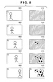
- Fig. 8 is a view for explaining a practical example of image composition according to the second embodiment of the present invention.
- Fig. 9 is a flowchart showing the processing to be executed by a mixed reality presentation apparatus according to the third embodiment of the present invention.
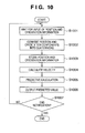
- Fig. 10 is a flowchart showing details of position and orientation prediction of a physical space image according to the third embodiment of the present invention.
- the aspect ratio and distortion parameters need to be calculated and processed at the same time during adjustment processing of the physical space image.
- this point is not essential to the present invention, a description about distortions and errors of the aspect ratio will not be given.
- the basic arrangement of a mixed reality presentation apparatus that implements the present invention is the same as that shown in Fig. 1 , except for its internal processing.
- a position and orientation measurement apparatus known as FASTRAK (trade name) available from Polhemus, U.S.A.
- the position and orientation measurement can also be implemented by a method of measuring only the orientation using a measuring device such as a gyro or the like, and measuring position information and drift errors of the orientation from a captured image.
- Fig. 4 is a block diagram showing the hardware arrangement of a PC which functions as the mixed reality presentation apparatus according to the first embodiment of the present invention.
- Fig. 5 is a flowchart showing the processing to be executed by the mixed reality presentation apparatus according to the first embodiment of the present invention.
- FIG. 5 the flowchart shown in Fig. 5 is implemented when, for example, a CPU 301 of the mixed reality presentation apparatus shown in Fig. 4 executes a control program stored in a main memory.
- step S401 the CPU 301 acquires position and orientation information from the position and orientation measurement values of an HMD measurement sensor 105 fixed to an HMD 101, and those of a physical space object measurement sensor 106 fixed to a physical space object 111. That is, the measurement values (position and orientation information) measured by these sensors are collected by a position and orientation measurement unit 104, which calculates position and orientation information indicating a relative position and orientation relationship between the viewpoint of the observer and a physical space object arranged in a physical space based on the two kinds of obtained position and orientation information.
- the position and orientation measurement unit 104 transmits the calculation results to a PC 103 via a communication unit such as a serial communication or the like.
- the PC 103 serves as a position and orientation information acquisition unit which acquires the position and orientation information indicating the relative position and orientation relationship between the viewpoint of the observer and the physical space object on the physical space from the position and orientation measurement unit 104.
- step S402 the CPU 301 renders a virtual space image according to a predetermined coordinate system in the main memory 302 based on the already acquired position and orientation information.
- image composition is made by superimposing a virtual space image on a physical space image as a background.
- a virtual space image is rendered first.
- the predetermined coordinate system is a three-dimensional coordinate system required to display the physical space image and virtual space image using a common coordinate system, and an origin required to define that coordinate system can be set as needed.
- a physical space image at a timing intended as an image to be composited can be prevented from being changed to that after that timing during rendering of the virtual space image in association with a physical space image used in composition.
- a graphics accelerator 303 renders, using the virtual space image which is stored by the CPU 301 in the main memory 302, that virtual space image on a frame memory 304.
- the graphics accelerator 303 simultaneously updates depth information of the virtual space image in a depth buffer 308.
- step S402 When the rendering in step S402 requires a time for about two frames, this means that the state of a physical image advances from an image 601 to an image 604 for virtual space images 613 and 614 in Fig. 6 .
- the state of a virtual space image to be composited is represented by images 611 to 614.
- step S403 the PC 103 acquires a physical space image from an image capturing unit 102 incorporated in the HMD 101.
- an image input device 306 converts the physical space image received from the HMD 101 into a predetermined format, and stores it in the main memory 302. In case of Fig. 6 , an image 605 is acquired.
- step S404 the CPU 301 renders the acquired physical space image in the main memory 302.
- the CPU 301 renders the physical space image in the main memory 302 in the frame memory 304.
- the CPU 301 controls the graphics accelerator 303 to superimpose and render the physical space image on a portion where the virtual space image is not rendered on the frame memory 304 using the depth information in the depth buffer 308.
- an image 615 in Fig. 6 can be obtained. In this way, the physical space image can be prevented from being overwritten on the virtual space image.
- permission or inhibition of overwriting can also be controlled using a stencil buffer 309 that stores control information for controlling whether to permit or inhibit overwriting of an image on a virtual space image.
- step S405 the CPU 301 outputs a composite image generated in step S404 to the HMD 101 using image output device 305.
- an observer can observe an image displayed on the HMD 101 as if a virtual object existing in the physical space were present. Also, this processing can minimize the time delay (time difference) between a physical space image at the intended timing of the observer, and that to be displayed.
- steps S401 to S405 are the processes for one frame.
- the CPU 301 checks in step S406 if an end notification based on an operation of the observer is input. If no end notification is input (NO in step S406), the process returns to step S401. On the other hand, if an end notification is input (YES in step S406), the processing ends.
- a physical space image to be composited intended by the user is acquired, and is superimposed and rendered on that virtual space image, thereby generating a composite image.
- a difference in the contents of a physical space image due to a delay of an image output time as a result of image processing can be minimized, and a composite image having the contents of a physical space image at a timing intended by the user can be presented.
- the second embodiment will explain an application example of the first embodiment.
- a mixed reality presentation apparatus displaying a translucent output image is often effective to improve the visibility of the observer.
- the second embodiment will explain an arrangement that implements such translucent display.
- Fig. 7 is a flowchart showing the processing executed by the mixed reality presentation apparatus of the second embodiment.
- a CPU 301 controls a graphics accelerator 303 to composite a physical space image by alpha blending in step 704.
- Fig. 8 shows a practical processing example according to the second embodiment of the present invention.
- virtual space images 813 and 814 are rendered to have a black background.
- alpha blending processing such as addition or the like
- a translucent effect can be obtained.
- a translucent-processed composite image 815 can be obtained.
- composite image 815 is expressed in black and white in Fig. 8 .
- translucent composition can be implemented.
- a translucent output image can be displayed as needed in addition to the effects described in the first embodiment.
- the third embodiment is an application example of the first embodiment.
- the first and second embodiments have explained the arrangement that reduces a time delay between the state of a physical space image at the current timing observed by the observer, and that of a physical image finally output to the HMD 101.
- position and orientation information which is required to generate a virtual space image and is acquired in step S401 may produce a time delay with respect to the position and orientation of an actual physical space object 111 upon acquisition of the physical space image.
- the third embodiment will explain image composition processing for reducing the time delay of the acquired position and orientation information.
- Fig. 9 is a flowchart showing the processing executed by the mixed reality presentation apparatus according to the third embodiment.
- a CPU 301 executes the position and orientation prediction of a physical space image in step S903 after the process in step S401 in Fig. 5 of the first embodiment.
- the CPU 301 renders a virtual space image in a main memory 302 based on the predicted values (position and orientation information) obtained in step S903.
- Fig. 10 is a flowchart showing details of the position and orientation prediction of a physical space image according to the third embodiment of the present invention.
- step S1001 the CPU 301 acquires position and orientation information.
- step S1002 the CPU 301 converts position and orientation components in the position and orientation information into quaternions.
- it is effective to convert position and orientation components into quaternions so as to attain predictive calculations such as linear prediction of position and orientation information or the like.
- the predictive calculation method is not limited to that using linear prediction. That is, any other methods may be used as long as they can attain predictive calculations.
- step S1003 the CPU 301 stores, in the main memory 302, the value indicating the position component, and the values indicating the position and orientation components converted into the quaternions in step S1002. Assume that pieces of position and orientation information corresponding to two previous frames (the values indicating the position components, and the position and orientation components) are stored in step S1003. When more accurate prediction that suffers less noise is required, it is effective to store pieces of position and orientation information corresponding to three or more frames (the values indicating the positions, and the positions and orientations).
- the number of frames to be stored may be set according to use applications and purposes, and it is not particularly limited.
- step S1004 the CPU 301 calculates the velocity of a physical space object based on the pieces of position and orientation information for two frames (the values indicating the positions, and the positions and orientations). Given, for example, uniform velocity movement, uniform rotation, or the like, the predicted value of the velocity can be easily calculated by linear prediction based on the pieces of position and orientation information for two frames (the values indicating the positions, and the positions and orientations).
- step S1005 the CPU 301 executes predictive calculations for calculating the predicted values of the position and orientation of the physical space object based on the calculated velocity.
- this predictive calculation method various methods are known as a method of estimating a predicted value by applying to a specific predictive calculation model, and the predictive calculation methods used in the present invention are not particularly limited.
- step S1006 the CPU 301 outputs the calculated predicted values.
- the CPU 301 checks in step S1007 if an end notification of the processing from a PC 103 is input. If no end notification is input (NO in step S1007), the process returns to step S1001. On the other hand, if an end notification is input (YES in step S1007), the processing ends.
- a virtual space image is rendered based on the predicted values indicating the position and orientation at the acquisition timing of a physical space image.
- a virtual space image and physical space image close to the state (the position and the position and orientation) upon acquisition of the physical image can be composited.
- the present invention can be applied to an apparatus comprising a single device or to system constituted by a plurality of devices.
- the invention can be implemented by supplying a software program, which implements the functions of the foregoing embodiments, directly or indirectly, to a system or apparatus, reading the supplied program code with a computer of the system or apparatus, and then executing the program code.
- a software program which implements the functions of the foregoing embodiments, directly or indirectly
- the system or apparatus reading the supplied program code with a computer of the system or apparatus, and then executing the program code.
- the mode of implementation need not rely upon a program.
- the program code installed in the computer also implements the present invention.
- the claims of the present invention also cover a computer program for the purpose of implementing the functions of the present invention.
- the program may be executed in any form, such as an object code, a program executed by an interpreter, or script data supplied to an operating system.
- Example of storage media that can be used for supplying the program are a floppy disk, a hard disk, an optical disk, a magneto-optical disk, a CD-ROM, a CD-R, a CD-RW, a magnetic tape, a non-volatile type memory card, a ROM, and a DVD (DVD-ROM and a DVD-R.
- a client computer can be connected to a website on the Internet using a browser of the client computer, and the computer program of the present invention or an automatically-installable compressed file of the program can be downloaded to a recording medium such as a hard disk.
- the program of the present invention can be supplied by dividing the program code constituting the program into a plurality of files and downloading the files from different websites.
- a WWW World Wide Web
- a storage medium such as a CD-ROM
- an operating system or the like running on the computer may perform all or a part of the actual processing so that the functions of the foregoing embodiments can be implemented by this processing.
- a CPU or the like mounted on the function expansion board or function expansion unit performs all or a part of the actual processing so that the functions of the foregoing embodiments can be implemented by this processing.
Landscapes
- Engineering & Computer Science (AREA)
- Computer Graphics (AREA)
- Physics & Mathematics (AREA)
- General Physics & Mathematics (AREA)
- Theoretical Computer Science (AREA)
- Computer Hardware Design (AREA)
- General Engineering & Computer Science (AREA)
- Software Systems (AREA)
- Multimedia (AREA)
- Signal Processing (AREA)
- Processing Or Creating Images (AREA)
- Image Generation (AREA)
Abstract
Description
- The present invention relates to a mixed reality presentation apparatus for compositing and presenting a physical space image and virtual space image together, and a control method thereof.
- In a mixed reality system, the viewpoint and line-of-sight direction of an operator, and the position of an object in a space need to be measured.
- As a position and orientation measurement system, the use of a position and orientation measurement apparatus known as FASTRAK (trade name) available from Polhemus, U.S.A. is a general method. Also, a method in which only the orientation is measured by a measuring device such as a gyro or the like, and position information and drift errors of the orientation are measured from an image, is known.
- The hardware arrangement and the sequence of processing of a general mixed reality presentation apparatus (disclosed in, for example, Japanese Patent Laid-Open No.
2005-107968 Figs. 1 and2 . - In this example, by superimposing a virtual space image 110 (an image of a virtual object) onto a physical space image of a
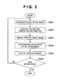
physical space object 111, a virtual object represented by thevirtual space image 110 can be displayed on thephysical space object 111 as if it existed in the physical space. Such function can be applied to verification of design and entertainment, for example. - In step S201, a PC (personal computer) 103 acquires a physical space image from an
image capturing unit 102 incorporated in an HMD (head mounted display) 101. - In step S202, the position and orientation measurements of an
HMD measurement sensor 105 fixed to theHMD 101, and those of a physical spaceobject measurement sensor 106 fixed to thephysical space object 111 are obtained. These measurement values are collected by a position andorientation measurement unit 104, and are fetched by the PC 103 as position and orientation information via a communication unit such as a serial communication or the like. - In step S203, the PC 103 renders a physical space image of the
physical space object 111 in its memory. - In step S204, a virtual space image is rendered in the memory of the
PC 103 according to the position and orientation measurement values of theimage capturing unit 102 and those of thephysical space object 111 acquired in step S202 so as to be superimposed on the physical space image. In this way, in the memory, a mixed reality image as a composite image of the physical space image and virtual space image is generated. - In step S205, the PC 103 transmits the composite image (mixed reality image) rendered in the memory of the PC 103 to the HMD 101, thereby displaying the composite image (mixed reality image) on the HMD 101.
- Steps S201 to S205 described above are the processes for one frame. The PC 103 checks in step S206 if an end notification based on an operation of the operator is input. If no end notification is input (NO in step S206), the process returns to step S201.
On the other hand, if an end notification is input (YES in step S206), the processing ends. - An example of the composite image obtained by the aforementioned processing will be described below with reference to
Fig. 3 . - Referring to
Fig. 3 ,images 501 to 505 are obtained by time-serially arranging physical space images obtained from theimage capturing unit 102.Images 511 to 514 time-serially represent the progress of the composition processing between the physical space image and virtual space image. - In this example, assume that the physical space image acquired in step S201 is the
image 501. After that, time elapses during the processes of steps S202 and S203, and the physical space image changes from theimage 501 to theimage 502. - Examples obtained by sequentially superimposing and rendering two virtual space images on the physical space image in step S204 are the
images - The finally obtained image (composite image) 514 is output in step S205. At this time, the physical space image already changes to the
image - In the aforementioned arrangement of the general mixed reality presentation apparatus, many steps need to be executed until the physical space image acquired in step S201 is displayed on the HMD 101. In particular, the processing for superimposing and rendering the virtual space images in step S204 requires a lot of time since their rendering is implemented by high-quality CG images.
- For this reason, when the composite image is displayed on the
HMD 101, a physical space image in the composite image to be actually presented to the observer is temporally delayed from a physical space image at that time, as shown inFig. 3 , thus making the observer feel unnatural. - The present invention has been made to address the aforementioned problems.
- The present invention in its first aspect provides a mixed reality presentation apparatus as specified in
claims 1 to 5. - The present invention in its second aspect provides a method of controlling a mixed reality presentation apparatus as specified in claim 6.
- The present invention in its third aspect provides a computer program stored in a computer-readable medium as specified in claim 7.
- Further features of the present invention will become apparent from the following description of exemplary embodiments with reference to the attached drawings.
-
Fig. 1 is a view showing the hardware arrangement of a known general mixed reality presentation apparatus; -
Fig. 2 is a flowchart showing the processing of the known general mixed reality presentation apparatus; -
Fig. 3 shows a practical example of known general image composition processing; -
Fig. 4 is a block diagram showing the hardware arrangement of a PC which functions as a mixed reality presentation apparatus according to the first embodiment of the present invention; -
Fig. 5 is a flowchart showing the processing to be executed by the mixed reality presentation apparatus according to the first embodiment of the present invention; -
Fig. 6 shows a practical example of image composition processing according to the first embodiment of the present invention; -
Fig. 7 is a flowchart showing the processing to be executed by a mixed reality presentation apparatus according to the second embodiment of the present invention; -
Fig. 8 is a view for explaining a practical example of image composition according to the second embodiment of the present invention; -
Fig. 9 is a flowchart showing the processing to be executed by a mixed reality presentation apparatus according to the third embodiment of the present invention; and -
Fig. 10 is a flowchart showing details of position and orientation prediction of a physical space image according to the third embodiment of the present invention. - Preferred embodiments of the present invention will now be described in detail with reference to the drawings. It should be noted that the relative arrangement of the components, the numerical expressions and numerical values set forth in these embodiments do not limit the scope of the present invention unless it is specifically stated otherwise.
- <First Embodiment> In the first embodiment, a description will be given assuming that the intrinsic parameters of an image capturing unit (camera) that acquired a physical space image are acquired as pre-processing, and when no image adjustment processing is applied, geometrical matching between a physical space image and virtual space image is attained.
- In order to accurately attain geometrical matching between the physical space image and virtual space image, the aspect ratio and distortion parameters need to be calculated and processed at the same time during adjustment processing of the physical space image. However, since this point is not essential to the present invention, a description about distortions and errors of the aspect ratio will not be given.
- The image composition processing as a characteristic feature of the present invention will now be described assuming that calibration of the intrinsic parameters of an image capturing unit (camera) and that of a position and orientation measurement unit are complete.
- The basic arrangement of a mixed reality presentation apparatus that implements the present invention is the same as that shown in
Fig. 1 , except for its internal processing. - As a position and orientation measurement system of the first embodiment, a position and orientation measurement apparatus known as FASTRAK (trade name) available from Polhemus, U.S.A. can be used. However, the position and orientation measurement can also be implemented by a method of measuring only the orientation using a measuring device such as a gyro or the like, and measuring position information and drift errors of the orientation from a captured image.
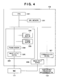
- Image composition by a mixed reality presentation apparatus of the first embodiment will be described below with reference to
Figs. 1 ,4 , and5 .Fig. 4 is a block diagram showing the hardware arrangement of a PC which functions as the mixed reality presentation apparatus according to the first embodiment of the present invention.Fig. 5 is a flowchart showing the processing to be executed by the mixed reality presentation apparatus according to the first embodiment of the present invention. - Note that the flowchart shown in
Fig. 5 is implemented when, for example, aCPU 301 of the mixed reality presentation apparatus shown inFig. 4 executes a control program stored in a main memory. - In step S401, the
CPU 301 acquires position and orientation information from the position and orientation measurement values of anHMD measurement sensor 105 fixed to anHMD 101, and those of a physical spaceobject measurement sensor 106 fixed to aphysical space object 111. That is, the measurement values (position and orientation information) measured by these sensors are collected by a position andorientation measurement unit 104, which calculates position and orientation information indicating a relative position and orientation relationship between the viewpoint of the observer and a physical space object arranged in a physical space based on the two kinds of obtained position and orientation information. The position andorientation measurement unit 104 transmits the calculation results to a PC 103 via a communication unit such as a serial communication or the like. - In this way, in the
PC 103, measurement data are sent to and stored in amain memory 302 via acommunication device 307. As a result, thePC 103 serves as a position and orientation information acquisition unit which acquires the position and orientation information indicating the relative position and orientation relationship between the viewpoint of the observer and the physical space object on the physical space from the position andorientation measurement unit 104. - In step S402, the
CPU 301 renders a virtual space image according to a predetermined coordinate system in themain memory 302 based on the already acquired position and orientation information. Normally, image composition is made by superimposing a virtual space image on a physical space image as a background. However, in the present invention, a virtual space image is rendered first. - Note that a high-resolution, high-quality virtual space image needs to be rendered depending on the mode of an application. In this case, the rendering requires a time of several frames or more of the video rate. The predetermined coordinate system is a three-dimensional coordinate system required to display the physical space image and virtual space image using a common coordinate system, and an origin required to define that coordinate system can be set as needed.
- In the present invention, since the virtual space image is rendered first, a physical space image at a timing intended as an image to be composited can be prevented from being changed to that after that timing during rendering of the virtual space image in association with a physical space image used in composition.
- At this time, in the
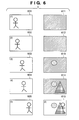
PC 103, agraphics accelerator 303 renders, using the virtual space image which is stored by theCPU 301 in themain memory 302, that virtual space image on aframe memory 304. In this case, thegraphics accelerator 303 simultaneously updates depth information of the virtual space image in adepth buffer 308. - When the rendering in step S402 requires a time for about two frames, this means that the state of a physical image advances from an
image 601 to animage 604 forvirtual space images Fig. 6 . InFig. 6 , the state of a virtual space image to be composited is represented byimages 611 to 614. - In step S403, the
PC 103 acquires a physical space image from animage capturing unit 102 incorporated in theHMD 101. At this time, in thePC 103, animage input device 306 converts the physical space image received from theHMD 101 into a predetermined format, and stores it in themain memory 302. In case ofFig. 6 , animage 605 is acquired. - In step S404, the
CPU 301 renders the acquired physical space image in themain memory 302. In thePC 103, theCPU 301 renders the physical space image in themain memory 302 in theframe memory 304. At this time, theCPU 301 controls thegraphics accelerator 303 to superimpose and render the physical space image on a portion where the virtual space image is not rendered on theframe memory 304 using the depth information in thedepth buffer 308. In this case, animage 615 inFig. 6 can be obtained. In this way, the physical space image can be prevented from being overwritten on the virtual space image. - As a method of preventing a physical space image from being overwritten on a virtual space image, permission or inhibition of overwriting can also be controlled using a
stencil buffer 309 that stores control information for controlling whether to permit or inhibit overwriting of an image on a virtual space image. - In step S405, the
CPU 301 outputs a composite image generated in step S404 to theHMD 101 usingimage output device 305. - With the above processing, an observer can observe an image displayed on the
HMD 101 as if a virtual object existing in the physical space were present. Also, this processing can minimize the time delay (time difference) between a physical space image at the intended timing of the observer, and that to be displayed. - As described above, steps S401 to S405 are the processes for one frame. The
CPU 301 checks in step S406 if an end notification based on an operation of the observer is input. If no end notification is input (NO in step S406), the process returns to step S401. On the other hand, if an end notification is input (YES in step S406), the processing ends. - As described above, according to the first embodiment, after a virtual space image is rendered, a physical space image to be composited intended by the user is acquired, and is superimposed and rendered on that virtual space image, thereby generating a composite image. In this way, a difference in the contents of a physical space image due to a delay of an image output time as a result of image processing can be minimized, and a composite image having the contents of a physical space image at a timing intended by the user can be presented.
- <Second Embodiment>
The second embodiment will explain an application example of the first embodiment. In a mixed reality presentation apparatus, displaying a translucent output image is often effective to improve the visibility of the observer. Hence, the second embodiment will explain an arrangement that implements such translucent display. - Note that the arrangement of a mixed reality presentation apparatus of the second embodiment can be implemented using the apparatus described in the first embodiment, and a detailed description thereof will not be repeated.
- The image composition processing by the mixed reality presentation apparatus of the second embodiment will be described below with reference to
Fig. 7 . -
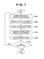
Fig. 7 is a flowchart showing the processing executed by the mixed reality presentation apparatus of the second embodiment. - Note that the same step numbers in
Fig. 7 denote the same processes as those inFig. 5 of the first embodiment, and a detailed description thereof will not be repeated. - Referring to
Fig. 7 , after the process in step S403, aCPU 301 controls agraphics accelerator 303 to composite a physical space image by alpha blending in step 704. -
Fig. 8 shows a practical processing example according to the second embodiment of the present invention. - Note that the same reference numerals in
Fig. 8 denote images common toFig. 6 of the first embodiment. - In
Fig. 8 ,virtual space images image 605 of a physical space image onto thevirtual space image 814 using alpha blending processing such as addition or the like, a translucent effect can be obtained. As a result, a translucent-processedcomposite image 815 can be obtained. - Note that the
composite image 815 is expressed in black and white inFig. 8 . However, in practice, translucent composition can be implemented. - As described above, according to the second embodiment, a translucent output image can be displayed as needed in addition to the effects described in the first embodiment.
- <Third Embodiment>
The third embodiment is an application example of the first embodiment. The first and second embodiments have explained the arrangement that reduces a time delay between the state of a physical space image at the current timing observed by the observer, and that of a physical image finally output to theHMD 101. In this arrangement, position and orientation information which is required to generate a virtual space image and is acquired in step S401 may produce a time delay with respect to the position and orientation of an actualphysical space object 111 upon acquisition of the physical space image. Hence, the third embodiment will explain image composition processing for reducing the time delay of the acquired position and orientation information. - The image composition processing by a mixed reality presentation apparatus according to the third embodiment will be described below with reference to
Fig. 9 . -
Fig. 9 is a flowchart showing the processing executed by the mixed reality presentation apparatus according to the third embodiment. - Note that the same step numbers in
Fig. 9 denote the same processes as those inFig. 5 of the first embodiment, and a detailed description thereof will not be repeated. - Particularly, in
Fig. 9 , aCPU 301 executes the position and orientation prediction of a physical space image in step S903 after the process in step S401 inFig. 5 of the first embodiment. In step S402a, theCPU 301 renders a virtual space image in amain memory 302 based on the predicted values (position and orientation information) obtained in step S903. - Details of this processing will be described below with reference to
Fig. 10 . -
Fig. 10 is a flowchart showing details of the position and orientation prediction of a physical space image according to the third embodiment of the present invention. - In step S1001, the
CPU 301 acquires position and orientation information. In step S1002, theCPU 301 converts position and orientation components in the position and orientation information into quaternions. As is generally known, it is effective to convert position and orientation components into quaternions so as to attain predictive calculations such as linear prediction of position and orientation information or the like. However, the predictive calculation method is not limited to that using linear prediction. That is, any other methods may be used as long as they can attain predictive calculations. - In step S1003, the
CPU 301 stores, in themain memory 302, the value indicating the position component, and the values indicating the position and orientation components converted into the quaternions in step S1002. Assume that pieces of position and orientation information corresponding to two previous frames (the values indicating the position components, and the position and orientation components) are stored in step S1003. When more accurate prediction that suffers less noise is required, it is effective to store pieces of position and orientation information corresponding to three or more frames (the values indicating the positions, and the positions and orientations). The number of frames to be stored may be set according to use applications and purposes, and it is not particularly limited. - In step S1004, the
CPU 301 calculates the velocity of a physical space object based on the pieces of position and orientation information for two frames (the values indicating the positions, and the positions and orientations). Given, for example, uniform velocity movement, uniform rotation, or the like, the predicted value of the velocity can be easily calculated by linear prediction based on the pieces of position and orientation information for two frames (the values indicating the positions, and the positions and orientations). - In step S1005, the
CPU 301 executes predictive calculations for calculating the predicted values of the position and orientation of the physical space object based on the calculated velocity. As this predictive calculation method, various methods are known as a method of estimating a predicted value by applying to a specific predictive calculation model, and the predictive calculation methods used in the present invention are not particularly limited. - In step S1006, the
CPU 301 outputs the calculated predicted values. TheCPU 301 checks in step S1007 if an end notification of the processing from aPC 103 is input. If no end notification is input (NO in step S1007), the process returns to step S1001. On the other hand, if an end notification is input (YES in step S1007), the processing ends. - By rendering a virtual space image using the predicted values obtained by the aforementioned processing method, image composition using a virtual space image which has a minimum time delay from the state upon acquisition of a physical space image even upon compositing to the physical space image later can be implemented.
- As described above, according to the third embodiment, a virtual space image is rendered based on the predicted values indicating the position and orientation at the acquisition timing of a physical space image. As a result, a virtual space image and physical space image close to the state (the position and the position and orientation) upon acquisition of the physical image can be composited.
- Note that the present invention can be applied to an apparatus comprising a single device or to system constituted by a plurality of devices.
- Furthermore, the invention can be implemented by supplying a software program, which implements the functions of the foregoing embodiments, directly or indirectly, to a system or apparatus, reading the supplied program code with a computer of the system or apparatus, and then executing the program code. In this case, so long as the system or apparatus has the functions of the program, the mode of implementation need not rely upon a program.
- Accordingly, since the functions of the present invention are implemented by computer, the program code installed in the computer also implements the present invention. In other words, the claims of the present invention also cover a computer program for the purpose of implementing the functions of the present invention.
- In this case, so long as the system or apparatus has the functions of the program, the program may be executed in any form, such as an object code, a program executed by an interpreter, or script data supplied to an operating system.
- Example of storage media that can be used for supplying the program are a floppy disk, a hard disk, an optical disk, a magneto-optical disk, a CD-ROM, a CD-R, a CD-RW, a magnetic tape, a non-volatile type memory card, a ROM, and a DVD (DVD-ROM and a DVD-R.
- As for the method of supplying the program, a client computer can be connected to a website on the Internet using a browser of the client computer, and the computer program of the present invention or an automatically-installable compressed file of the program can be downloaded to a recording medium such as a hard disk. Further, the program of the present invention can be supplied by dividing the program code constituting the program into a plurality of files and downloading the files from different websites. In other words, a WWW (World Wide Web) server that downloads, to multiple users, the program files that implement the functions of the present invention by computer is also covered by the claims of the present invention.
- It is also possible to encrypt and store the program of the present invention on a storage medium such as a CD-ROM, distribute the storage medium to users, allow users who meet certain requirements to download decryption key information from a website via the Internet, and allow these users to decrypt the encrypted program by using the key information, whereby the program is installed in the user computer.
- Besides the cases where the aforementioned functions according to the embodiments are implemented by executing the read program by computer, an operating system or the like running on the computer may perform all or a part of the actual processing so that the functions of the foregoing embodiments can be implemented by this processing.
- Furthermore, after the program read from the storage medium is written to a function expansion board inserted into the computer or to a memory provided in a function expansion unit connected to the computer, a CPU or the like mounted on the function expansion board or function expansion unit performs all or a part of the actual processing so that the functions of the foregoing embodiments can be implemented by this processing.
- While the present invention has been described with reference to exemplary embodiments, it is to be understood that the invention is not limited to the disclosed exemplary embodiments. The scope of the following claims is to be accorded the broadest interpretation so as to encompass all such modifications and equivalent structures and functions.
Claims (8)
- A mixed reality presentation apparatus for compositing a physical space image and a virtual space image, and presenting a composite image, comprising:position and orientation information acquisition means (103) configured to acquire position and orientation information indicating a relative position and orientation relationship between a viewpoint of an observer and a physical space object in a physical space;rendering means (301) configured to generate a virtual space image based on the position and orientation information acquired by said position and orientation information acquisition means, and to render the generated virtual space image in a memory (304);acquisition means (306) configured to acquire a physical space image of the physical space object;composition means (303) configured to combine the physical space image and the generated virtual space image by rendering the physical space image acquired by said acquisition means in the memory in which the virtual space image has already been rendered; andoutput means (305) configured to output the composite image obtained by said composition means.
- The apparatus according to claim 1, further comprising a depth buffer (308) for storing depth information of the virtual space image,
wherein said composition means combines the physical space image and the virtual space image by rendering the physical space image in a portion of the memory where the virtual space image is not rendered using the depth information stored in said depth buffer. - The apparatus according to claim 1, further comprising a stencil buffer (309) for storing control information used to control whether to permit or inhibit overwriting of an image in the virtual space image,
wherein said composition means combines the physical space image and the virtual space image by rendering the physical space image so as to prevent the virtual space image in the memory from being overwritten by the physical space image using the control information stored in said stencil buffer. - The apparatus according any preceding claim, characterized in that said composition means combines the physical space image and the virtual space image by alpha blending.
- The apparatus according to any preceding claim, further comprising prediction means (301) configured to predict position and orientation information used for rendering of the virtual space image by said rendering means based on the position and orientation information acquired by said position and orientation information acquisition means.
- A method of controlling a mixed reality presentation apparatus for compositing a physical space image and a virtual space image, and presenting a composite image, comprising:acquiring position and orientation information indicating a relative position and orientation relationship between a viewpoint of an observer and a physical space object in a physical space;generating a virtual space image based on the position and orientation information acquired in the position and orientation information acquisition step, and rendering the generated virtual space image in a memory;acquiring a physical space image of the physical space object;compositing the physical space image and the virtual space image by rendering the physical space image acquired in the acquisition step in the memory in which the virtual space image has already been rendered; andoutputting the composite image obtained in the composition step.
- A computer program which when loaded into a computer and executed configures the computer to function as a mixed reality presentation apparatus as claimed in any one of claims 1 to 5.
- A machine-readable storage means storing a computer program as claimed in claim 7.
Applications Claiming Priority (1)
| Application Number | Priority Date | Filing Date | Title |
|---|---|---|---|
| JP2007137014A JP4909176B2 (en) | 2007-05-23 | 2007-05-23 | Mixed reality presentation apparatus, control method therefor, and computer program |
Publications (2)
| Publication Number | Publication Date |
|---|---|
| EP1995694A2 true EP1995694A2 (en) | 2008-11-26 |
| EP1995694A3 EP1995694A3 (en) | 2017-02-15 |
Family
ID=39739916
Family Applications (1)
| Application Number | Title | Priority Date | Filing Date |
|---|---|---|---|
| EP08156848.7A Withdrawn EP1995694A3 (en) | 2007-05-23 | 2008-05-23 | Mixed reality presentation apparatus and control method |
Country Status (5)
| Country | Link |
|---|---|
| US (1) | US20080291219A1 (en) |
| EP (1) | EP1995694A3 (en) |
| JP (1) | JP4909176B2 (en) |
| KR (1) | KR100958511B1 (en) |
| CN (1) | CN101311893B (en) |
Cited By (1)
| Publication number | Priority date | Publication date | Assignee | Title |
|---|---|---|---|---|
| EP3193327A4 (en) * | 2014-09-08 | 2018-03-07 | The University of Tokyo | Image processing device and image processing method |
Families Citing this family (26)
| Publication number | Priority date | Publication date | Assignee | Title |
|---|---|---|---|---|
| US8560047B2 (en) | 2006-06-16 | 2013-10-15 | Board Of Regents Of The University Of Nebraska | Method and apparatus for computer aided surgery |
| JP5047090B2 (en) * | 2008-07-31 | 2012-10-10 | キヤノン株式会社 | system |
| US9600067B2 (en) * | 2008-10-27 | 2017-03-21 | Sri International | System and method for generating a mixed reality environment |
| JP2011159163A (en) * | 2010-02-02 | 2011-08-18 | Sony Corp | Image processing device, image processing method, and program |
| JP5728159B2 (en) | 2010-02-02 | 2015-06-03 | ソニー株式会社 | Image processing apparatus, image processing method, and program |
| KR20110099414A (en) * | 2010-03-02 | 2011-09-08 | 삼성전자주식회사 | Apparatus and method for providing animation effect in portable terminal |
| CN102004552A (en) * | 2010-12-06 | 2011-04-06 | 深圳泰山在线科技有限公司 | Tracking point identification based method and system for increasing on-site sport experience of users |
| JP5734080B2 (en) * | 2011-05-10 | 2015-06-10 | キヤノン株式会社 | Information processing apparatus, processing method thereof, and program |
| CA2840397A1 (en) | 2011-06-27 | 2013-04-11 | Board Of Regents Of The University Of Nebraska | On-board tool tracking system and methods of computer assisted surgery |
| US11911117B2 (en) | 2011-06-27 | 2024-02-27 | Board Of Regents Of The University Of Nebraska | On-board tool tracking system and methods of computer assisted surgery |
| US9498231B2 (en) | 2011-06-27 | 2016-11-22 | Board Of Regents Of The University Of Nebraska | On-board tool tracking system and methods of computer assisted surgery |
| CN103020065B (en) * | 2011-09-22 | 2016-09-07 | 北京神州泰岳软件股份有限公司 | The signature plate implementation method of a kind of sing on web page and a kind of Web system |
| CN103028252B (en) * | 2011-09-29 | 2014-12-31 | 泉阳兴业株式会社 | Tourist car |
| US9129429B2 (en) | 2012-10-24 | 2015-09-08 | Exelis, Inc. | Augmented reality on wireless mobile devices |
| US10105149B2 (en) | 2013-03-15 | 2018-10-23 | Board Of Regents Of The University Of Nebraska | On-board tool tracking system and methods of computer assisted surgery |
| KR101800949B1 (en) | 2013-04-24 | 2017-11-23 | 가와사끼 쥬고교 가부시끼 가이샤 | Workpiece machining work support system and workpiece machining method |
| JP6344890B2 (en) | 2013-05-22 | 2018-06-20 | 川崎重工業株式会社 | Component assembly work support system and component assembly method |
| US20160077166A1 (en) * | 2014-09-12 | 2016-03-17 | InvenSense, Incorporated | Systems and methods for orientation prediction |
| CN105635745B (en) * | 2015-12-23 | 2019-10-22 | 广州华多网络科技有限公司 | Method and client that signature shines are generated based on online live streaming application |
| JP2017123050A (en) * | 2016-01-07 | 2017-07-13 | ソニー株式会社 | Information processor, information processing method, program, and server |
| CN107277495B (en) * | 2016-04-07 | 2019-06-25 | 深圳市易瞳科技有限公司 | A kind of intelligent glasses system and its perspective method based on video perspective |
| KR101724360B1 (en) * | 2016-06-30 | 2017-04-07 | 재단법인 실감교류인체감응솔루션연구단 | Mixed reality display apparatus |
| KR20190070423A (en) | 2017-12-13 | 2019-06-21 | 주식회사 투스라이프 | Virtual-Reality-based Attachable-Tracker with Detect Real Motion |
| CN110412765B (en) * | 2019-07-11 | 2021-11-16 | Oppo广东移动通信有限公司 | Augmented reality image shooting method and device, storage medium and augmented reality equipment |
| US20230039690A1 (en) | 2020-01-14 | 2023-02-09 | Ntt Docomo, Inc. | Image display device |
| KR102442715B1 (en) * | 2020-12-02 | 2022-09-14 | 한국전자기술연구원 | Apparatus and method for reproducing augmented reality image based on divided rendering image |
Citations (1)
| Publication number | Priority date | Publication date | Assignee | Title |
|---|---|---|---|---|
| JP2005107968A (en) | 2003-09-30 | 2005-04-21 | Canon Inc | Image display device and method, and information processing method |
Family Cites Families (20)
| Publication number | Priority date | Publication date | Assignee | Title |
|---|---|---|---|---|
| JPH09245192A (en) * | 1996-03-08 | 1997-09-19 | Canon Inc | Method for realizing virtual environment generation realizing and its device |
| JP3724117B2 (en) * | 1997-05-23 | 2005-12-07 | ソニー株式会社 | Image generating apparatus and image generating method |
| JP3490983B2 (en) * | 2001-05-30 | 2004-01-26 | コナミ株式会社 | Image processing method and image processing program |
| JP3584229B2 (en) * | 2001-09-28 | 2004-11-04 | キヤノン株式会社 | Video experience system and information processing method |
| JP2003346190A (en) | 2002-05-29 | 2003-12-05 | Canon Inc | Image processor |
| JP4298407B2 (en) * | 2002-09-30 | 2009-07-22 | キヤノン株式会社 | Video composition apparatus and video composition method |
| US7427996B2 (en) * | 2002-10-16 | 2008-09-23 | Canon Kabushiki Kaisha | Image processing apparatus and image processing method |
| CA2523727A1 (en) * | 2003-04-28 | 2005-01-06 | Bracco Imaging Spa | Surgical navigation imaging system |
| JP4401728B2 (en) * | 2003-09-30 | 2010-01-20 | キヤノン株式会社 | Mixed reality space image generation method and mixed reality system |
| JP4393169B2 (en) * | 2003-12-04 | 2010-01-06 | キヤノン株式会社 | Mixed reality presentation method and apparatus |
| JP4522129B2 (en) * | 2004-03-31 | 2010-08-11 | キヤノン株式会社 | Image processing method and image processing apparatus |
| JP4227561B2 (en) * | 2004-06-03 | 2009-02-18 | キヤノン株式会社 | Image processing method and image processing apparatus |
| JP3779717B2 (en) | 2004-08-31 | 2006-05-31 | コナミ株式会社 | GAME PROGRAM AND GAME DEVICE |
| US20060050070A1 (en) * | 2004-09-07 | 2006-03-09 | Canon Kabushiki Kaisha | Information processing apparatus and method for presenting image combined with virtual image |
| JP2008520052A (en) * | 2004-11-12 | 2008-06-12 | モク3, インコーポレイテッド | Method for transition between scenes |
| JP2006215939A (en) | 2005-02-07 | 2006-08-17 | Kumamoto Univ | Free viewpoint image composition method and device |
| JP4144888B2 (en) * | 2005-04-01 | 2008-09-03 | キヤノン株式会社 | Image processing method and image processing apparatus |
| JP2007004714A (en) * | 2005-06-27 | 2007-01-11 | Canon Inc | Information processing method and information processing unit |
| US8094928B2 (en) | 2005-11-14 | 2012-01-10 | Microsoft Corporation | Stereo video for gaming |
| JP5196729B2 (en) * | 2006-04-11 | 2013-05-15 | 任天堂株式会社 | Communication game system |
-
2007
- 2007-05-23 JP JP2007137014A patent/JP4909176B2/en not_active Expired - Fee Related
-
2008
- 2008-05-02 US US12/114,007 patent/US20080291219A1/en not_active Abandoned
- 2008-05-23 CN CN2008100983159A patent/CN101311893B/en not_active Expired - Fee Related
- 2008-05-23 EP EP08156848.7A patent/EP1995694A3/en not_active Withdrawn
- 2008-05-23 KR KR1020080048193A patent/KR100958511B1/en not_active IP Right Cessation
Patent Citations (1)
| Publication number | Priority date | Publication date | Assignee | Title |
|---|---|---|---|---|
| JP2005107968A (en) | 2003-09-30 | 2005-04-21 | Canon Inc | Image display device and method, and information processing method |
Cited By (1)
| Publication number | Priority date | Publication date | Assignee | Title |
|---|---|---|---|---|
| EP3193327A4 (en) * | 2014-09-08 | 2018-03-07 | The University of Tokyo | Image processing device and image processing method |
Also Published As
| Publication number | Publication date |
|---|---|
| JP2008293209A (en) | 2008-12-04 |
| CN101311893A (en) | 2008-11-26 |
| EP1995694A3 (en) | 2017-02-15 |
| CN101311893B (en) | 2011-08-31 |
| KR20080103469A (en) | 2008-11-27 |
| US20080291219A1 (en) | 2008-11-27 |
| KR100958511B1 (en) | 2010-05-17 |
| JP4909176B2 (en) | 2012-04-04 |
Similar Documents
| Publication | Publication Date | Title |
|---|---|---|
| EP1995694A2 (en) | Mixed reality presentation apparatus and control method | |
| US8055061B2 (en) | Method and apparatus for generating three-dimensional model information | |
| US7589747B2 (en) | Mixed reality space image generation method and mixed reality system | |
| JP4857196B2 (en) | Head-mounted display device and control method thereof | |
| JP4847203B2 (en) | Information processing method and information processing apparatus | |
| US7728852B2 (en) | Image processing method and image processing apparatus | |
| US20100026714A1 (en) | Mixed reality presentation system | |
| US20070236510A1 (en) | Image processing apparatus, control method thereof, and program | |
| US20130278636A1 (en) | Object display device, object display method, and object display program | |
| US20130342573A1 (en) | Transitioning 3D Space Information to Screen Aligned Information for Video See Through Augmented Reality | |
| EP3572916A2 (en) | Apparatus, system, and method for accelerating positional tracking of head-mounted displays | |
| RU2677594C2 (en) | Information processing apparatus, information processing method and program | |
| US10692420B2 (en) | Data processing systems | |
| JP2005038321A (en) | Head mount display device | |
| JP4144888B2 (en) | Image processing method and image processing apparatus | |
| JP2008146497A (en) | Image processor and image processing method | |
| WO2019163558A1 (en) | Image processing device, image processing method, and program | |
| KR102218843B1 (en) | Multi-camera augmented reality broadcasting system based on overlapping layer using stereo camera and providing method thereof | |
| JP2018092228A (en) | Information processing terminal, control method of information processing terminal and program | |
| US20210183151A1 (en) | Method and apparatus for providing video information | |
| JP2005157611A (en) | Image processor and image processing method | |
| KR20190048857A (en) | Apparatus and method for authoring augmented reality contents | |
| US8817190B2 (en) | Image processing apparatus, image processing method, and computer program | |
| JP5075659B2 (en) | Object trajectory calculation device and program thereof | |
| JP2002042158A (en) | Image composing device, image composing method, and medium recording program |
Legal Events
| Date | Code | Title | Description |
|---|---|---|---|
| PUAI | Public reference made under article 153(3) epc to a published international application that has entered the european phase |
Free format text: ORIGINAL CODE: 0009012 |
|
| AK | Designated contracting states |
Kind code of ref document: A2 Designated state(s): AT BE BG CH CY CZ DE DK EE ES FI FR GB GR HR HU IE IS IT LI LT LU LV MC MT NL NO PL PT RO SE SI SK TR |
|
| AX | Request for extension of the european patent |
Extension state: AL BA MK RS |
|
| RIC1 | Information provided on ipc code assigned before grant |
Ipc: G06T 17/40 00000000AFI20160831BHEP |
|
| PUAL | Search report despatched |
Free format text: ORIGINAL CODE: 0009013 |
|
| AK | Designated contracting states |
Kind code of ref document: A3 Designated state(s): AT BE BG CH CY CZ DE DK EE ES FI FR GB GR HR HU IE IS IT LI LT LU LV MC MT NL NO PL PT RO SE SI SK TR |
|
| AX | Request for extension of the european patent |
Extension state: AL BA MK RS |
|
| RIC1 | Information provided on ipc code assigned before grant |
Ipc: G06T 17/40 00000000AFI20170111BHEP |
|
| 17P | Request for examination filed |
Effective date: 20170816 |
|
| RBV | Designated contracting states (corrected) |
Designated state(s): AT BE BG CH CY CZ DE DK EE ES FI FR GB GR HR HU IE IS IT LI LT LU LV MC MT NL NO PL PT RO SE SI SK TR |
|
| AKX | Designation fees paid |
Designated state(s): DE FR GB IT NL |
|
| AXX | Extension fees paid |
Extension state: RS Extension state: AL Extension state: MK Extension state: BA |
|
| 17Q | First examination report despatched |
Effective date: 20180220 |
|
| STAA | Information on the status of an ep patent application or granted ep patent |
Free format text: STATUS: THE APPLICATION HAS BEEN WITHDRAWN |
|
| 18W | Application withdrawn |
Effective date: 20180524 |