EP1995684A2 - Verfahren zur Steuerung eines optischen Scanners und optischer Scanner - Google Patents
Verfahren zur Steuerung eines optischen Scanners und optischer Scanner Download PDFInfo
- Publication number
- EP1995684A2 EP1995684A2 EP08009249A EP08009249A EP1995684A2 EP 1995684 A2 EP1995684 A2 EP 1995684A2 EP 08009249 A EP08009249 A EP 08009249A EP 08009249 A EP08009249 A EP 08009249A EP 1995684 A2 EP1995684 A2 EP 1995684A2
- Authority
- EP
- European Patent Office
- Prior art keywords
- housing
- scanning
- flipper
- movement
- sense signal
- Prior art date
- Legal status (The legal status is an assumption and is not a legal conclusion. Google has not performed a legal analysis and makes no representation as to the accuracy of the status listed.)
- Withdrawn
Links
Images


Classifications
-
- G—PHYSICS
- G06—COMPUTING OR CALCULATING; COUNTING
- G06K—GRAPHICAL DATA READING; PRESENTATION OF DATA; RECORD CARRIERS; HANDLING RECORD CARRIERS
- G06K7/00—Methods or arrangements for sensing record carriers, e.g. for reading patterns
- G06K7/10—Methods or arrangements for sensing record carriers, e.g. for reading patterns by electromagnetic radiation, e.g. optical sensing; by corpuscular radiation
- G06K7/10544—Methods or arrangements for sensing record carriers, e.g. for reading patterns by electromagnetic radiation, e.g. optical sensing; by corpuscular radiation by scanning of the records by radiation in the optical part of the electromagnetic spectrum
- G06K7/10821—Methods or arrangements for sensing record carriers, e.g. for reading patterns by electromagnetic radiation, e.g. optical sensing; by corpuscular radiation by scanning of the records by radiation in the optical part of the electromagnetic spectrum further details of bar or optical code scanning devices
- G06K7/10881—Methods or arrangements for sensing record carriers, e.g. for reading patterns by electromagnetic radiation, e.g. optical sensing; by corpuscular radiation by scanning of the records by radiation in the optical part of the electromagnetic spectrum further details of bar or optical code scanning devices constructional details of hand-held scanners
-
- G—PHYSICS
- G06—COMPUTING OR CALCULATING; COUNTING
- G06K—GRAPHICAL DATA READING; PRESENTATION OF DATA; RECORD CARRIERS; HANDLING RECORD CARRIERS
- G06K7/00—Methods or arrangements for sensing record carriers, e.g. for reading patterns
- G06K7/10—Methods or arrangements for sensing record carriers, e.g. for reading patterns by electromagnetic radiation, e.g. optical sensing; by corpuscular radiation
- G06K7/10544—Methods or arrangements for sensing record carriers, e.g. for reading patterns by electromagnetic radiation, e.g. optical sensing; by corpuscular radiation by scanning of the records by radiation in the optical part of the electromagnetic spectrum
- G06K7/10554—Moving beam scanning
- G06K7/10594—Beam path
- G06K7/10603—Basic scanning using moving elements
- G06K7/10633—Basic scanning using moving elements by oscillation
- G06K7/10643—Activating means
- G06K7/10653—Activating means using flexible or piezoelectric means
-
- G—PHYSICS
- G06—COMPUTING OR CALCULATING; COUNTING
- G06K—GRAPHICAL DATA READING; PRESENTATION OF DATA; RECORD CARRIERS; HANDLING RECORD CARRIERS
- G06K7/00—Methods or arrangements for sensing record carriers, e.g. for reading patterns
- G06K7/10—Methods or arrangements for sensing record carriers, e.g. for reading patterns by electromagnetic radiation, e.g. optical sensing; by corpuscular radiation
- G06K7/10544—Methods or arrangements for sensing record carriers, e.g. for reading patterns by electromagnetic radiation, e.g. optical sensing; by corpuscular radiation by scanning of the records by radiation in the optical part of the electromagnetic spectrum
- G06K7/10821—Methods or arrangements for sensing record carriers, e.g. for reading patterns by electromagnetic radiation, e.g. optical sensing; by corpuscular radiation by scanning of the records by radiation in the optical part of the electromagnetic spectrum further details of bar or optical code scanning devices
- G06K7/10851—Circuits for pulse shaping, amplifying, eliminating noise signals, checking the function of the sensing device
Definitions
- the invention concerns method for controlling an optical scanner and an optical scanning apparatus, especially for triggering a change of state of a scanner mechanism from an idle or non-scanning state to an active scanning state, upon detecting movement of a resilient element provided in the scanning mechanism.
- the movable element is the resonating flipper element that carries a reflector for scanning the beam, being driven in a feedback loop by an oscillator that is gated off during periods of inactivity.
- At least one mode for switching from the idle state to the active scanning state comprises setting a latch from an output of a feedback amplifier in the driving circuit.
- the circuit is useful to verify that movement has commenced when switching into the active state via a different mode.
- Bar code readers and similar beam scanning devices are used in various environments such as capturing product identification codes at retail point-of-sale stations, inventory and document tracking, order assembly and shipping and receiving, and in various other automatic data capture situations.
- An illuminating beam typically is scanned repeatedly over the code, using one or more reflectors that are moved so as to direct the beam from a fixed laser diode or the like along a scanning path.
- a flexible resilient polymer strip is fixed to a housing at one end, has a reflector on a side of the strip, and carries a magnet spaced from the fixed end. The magnet is subjected to electromagnetic force by an oscillator coupled to a coil that causes the strip to oscillate back and forth, thus tilting the reflector back and forth and directing the beam repetitively back and forth along a scan line.
- Such a scanner may be mounted in or on a countertop or adjacent to a conveyor.
- the scanner may comprise a movable scanning head that the user aims at the bar code.
- the scanning head may be tethered by a cable for managing power and communications lines, or may be self contained, battery powered and arranged for uploading data from time to time.
- Battery powered hand-held scanners may be arranged to connect to a power and data communications connection (such as a USB port) or to dock in a stand at which the battery of the hand-held scanner can be charged.
- the device is not typically used in for scanning when in the stand, and power consumption and battery life are product design issues.
- hand-held scanners often have three distinct modes, namely "on,” “off” and a standby or “sleep" mode.
- the sleep mode some circuit sections are at least partly disabled or unpowered, including the oscillator that electromechanically powers the scanner.
- a scanner may be configured automatically to enter the sleep mode if a predetermined time period elapses without scanning a readable bar code.
- a quiescent scanner When the scanner is in sleep mode, arrangements are provided in response to some signal or switch closure or sensed event to reactivate or "wake-up" the scanner as needed to resume regular operation.
- Several of methods for waking scanners and similar devices are known in the art.
- One method of activating a quiescent scanner involves changing the state of a switch or trigger mechanism on a scanner head that a human user grasps, lifts from a dock or cradle or otherwise moves when commencing to aim the scanning head at a bar code to be read.
- the trigger mechanism may comprise a touch plate coupled to a circuit responsive to a change of capacitance that occurs when a human touches the device.
- a mechanically operated conductive trigger switch may be included that must be depressed or released or toggled.
- Other possibilities include tilt or weight responsive switches for a standing unit, magnetic or inductive couplings with a docking base, etc. Wake up switches and interlocks as described are not wholly satisfactory because they add expense and complication.
- One method of triggering a change from quiescent to active operation is to detect that the scanning head has been redirected, potentially to be aimed, or that an item has been brought in front of the scanner, presumably to be scanned.
- an infrared (IR) detector can be used to generate an activation triggering signal when the subjects in the field of view move relative to the detector. This technique is functionally apt because attempting a scan generally involves changing the position of the scanner relative to an item to be scanned or relative to fixed background items.
- an IR source and detection circuits carry an associated expense in terms of parts, maintenance and power dissipation overhead.
- the power drain is particularly heavy because it is necessary to emit and detect IR signals throughout the period in which the scanner is quiescent in order to detect a movement of subjects in front of the scanner when it finally occurs. This technique is generally unsuitable if the scanner is to run on battery power.
- Another known method of waking a scanner comprises intermittently activating the scanner according to a timer, at least to the extent necessary to determine from a test or partial scan that a bar code may be present (e.g., to detect contrasting brightness along a line in the field of view).
- the scanning assembly e.g., the light source, oscillating mirror assembly and accompanying electrical circuitry
- the time interval between attempts needs to be relatively short because otherwise a user who wants to scan an item might be required to wait an undue time for the scanner to activate.
- a potential data signal is returned, for example as a reflected light signal containing light and dark transitions characteristic of bar code information, then the scanner is activated, comes up to full operation and scans repetitively for a time.
- This test scanning method likewise consumes a good deal of battery power in determining when to switch into the active mode.
- Scanning a bar code typically involves applying an illuminating beam and accumulating a response signal for a number of scanning repetitions.
- the reflected signal is accumulated and averaged, thereby reducing the adverse effects of some kinds of damage or dirt on a barcode label.
- the scanner may be inductively or electromagnetically coupled to a stand or base or docking station for charging. It still may be advisable to switch the device between modes of operation. For example, the scanner might be activated for scanning upon detection of its being manually removed from a charging stand.
- One way of generating an in-stand versus out-of-stand signal is to provide a magnet and a responsive Hall effect switch that interact when the scanner is on the charging stand. Components and circuitry are thus needed to generate an in-stand/-out-of-stand signal, which contribute to the cost of the scanner unit.
- a modest vibration in the resilient or resonant part of the scanning mechanism occurs whenever the scanner head is picked up for scanning or jarred or bumped or otherwise vibrated.
- the resilient or resonant scanner mechanism is driven in the active mode in a feedback loop.
- the scanner can comprise a resilient flipper having a strip of Kapton or another durable resilient polymer affixed to a mounting at one end, and bearing a reflector and a magnet.
- a relatively modest motion of the scanner head momentarily displaces the flipper, moving the magnet toward and away from a sensing coil and commencing the active scanning mode.
- the active drive continues to resonate the flipper for a predetermined time, and can be stopped after an interval during which no scannable code is detected.
- the method for sensing movement of an optical scanner comprises the steps of establishing an oscillating system with a resilient or similarly movable member.
- a permanent magnet and/or one or more electromagnetic coils are provided, one being on the movable member and one being fixed, for applying an electromagnetic force, at least intermittently, to displace the movable member and cause the movable member to oscillate.
- a motion or proximity sensing circuit is coupled to generate a first electrical signal upon displacement of the movable member. This signal is coupled to trigger a circuit that is provided for one of indicating a moving stated of the movable member and gating an oscillator the drives the movable member by applying the electromagnetic force in timed relationship to the displacement of the movable member.
- the indicator function can provide an input to a further circuit such as a controller, for verifying powered oscillation.
- the gating function is used to establish and maintain oscillation for a predetermined time interval after the first electrical signal detects vibration or displacement of the movable member.
- the movable member is a resiliently mounted flipper carrying a beam scanning reflector and a permanent magnet.
- Two electromagnetic coils are provided. One of the coils provides an input to an amplifier due to changing magnetic flux from motion of the magnet. The other coil is driven from an output of the amplifier to drive displacement of the movable member from a rest position during oscillation.
- the output of the amplifier sets a latch when triggered by displacement of the movable member. This latch can switch-on with detection of motion and can be used as an input to a gate or timer to enable oscillation to continue for a predetermined time that is usually sufficient to complete a scanning operation.
- the latch can be reset and the oscillation gated off, allowing oscillation of the movable member to diminish to zero in the idle state of the apparatus.
- the oscillating system remains idle until the movable member is moved or vibrated, e.g., by manually picking up a scanning head containing the movable member in preparation to scan a code. This triggers the device to resume powered oscillation.
- the apparatus can be employed with a controller or other circuit to develop a logic status signal representing active motion.
- This signal is useful not only for triggering or enabling powered oscillation, but also as a diagnostic status signal.
- the oscillator is driving the coil or coils with the signals needed for powered oscillation, the lack of a true status signal representing active motion can represent a failure condition. This situation may occur, for example if the scanning mechanism has been damaged or has become stuck.
- the disclosed apparatus and method are advantageously applied to a barcode scanner with a flipper assembly carrying a reflector and a magnet.
- the flipper assembly can have a resilient plastic strip of Kapton or the like, fixed at one end to a housing and carrying a reflective film and a permanent magnet subject to one or more coils mounted on the housing in position to displace the resilient strip and thus tilt the reflective film to scan a laser beam.
- a sensing circuit comprising an electromagnetic coil is configured to generated a current a signal due to movement of the magnet relative to the coil, which occurs upon displacement of the plastic strip relative to the housing.
- the current signal is amplified and used to drive a latch, flip-flop or similar logic element to provide a status indication that the device is in motion. This status indication can be used for initiating operation in an active state (i.e., to wake up the oscillator after an idle period) or for an operational status indicator (i.e., true when the plastic strip is moving) for other purposes as desired.
- FIG. 1 is a schematic isometric view showing certain aspects of an exemplary embodiment of the inventive oscillating system as applied to a beam scanner.
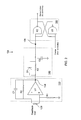
- FIG. 2 is a schematic circuit diagram showing a motion sensing portion of a circuit according to the invention.
- FIG. 3 is a block diagram illustrating the application of the invention to a scanning oscillator arrangement governed by a controller.
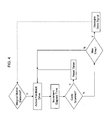
- Fig. 4 is a flow chart illustrating certain time-out operational aspects for switching between active and sleep modes.
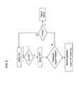
- Fig. 5 is a flow chart illustrating operation in a self test mode.
- Fig. 1 illustrates a practical embodiment of a scanning device having a flipper carrying a reflector and a magnet for scanning a beam incident on the reflector from a laser beam source.
- Fig. 2 shows a practical motion sensing circuit employed to provide a signal that indicates whether the physically movable part of the scanning device, namely the flipper, is moving.
- the circuit of Fig. 2 can be used, for example, in a larger controlled device for commencing scanning operations when the apparatus is subjected to movement, discussed in the general depiction of Fig. 3 .
- the device is operable in any orientation or configuration wherein the permanent and/or electromagnets are within operable range of one another and are oriented to urge or to detect displacement of the flipper from a rest position.
- the resilient scanning element of invention is exemplified in this description by a Kapton polyimide resilient flipper strip, carrying a reflector that tilts during resilient displacement and oscillation to direct a reflected beam over a scanning path.
- This particular material and structure is apt for barcode scanners and other devices and readily can exploit the feedback drive and motion detection capabilities of the invention.
- this disclosure hereby explicitly incorporates the full teachings of U.S. Patent No. 6,227,450 , regarding the structure and operation of resilient flipper scanner apparatus, as if fully set forth herein.
- FIG. 1 illustrates an electromechanically driven oscillating mechanism 100 according to one embodiment of the present disclosure.
- the oscillating member 106 in this case is shown as a resilient strip attached at a fixed end to a mounting block 104. Spaced from the fixed end, the oscillating member or strip (sometimes termed a "flipper" in this disclosure) has a reflector 108 on one side, such as a metallic film laminated with the strip, and a magnet 110 spaced from the fixed end, e.g., being mounted on the end of the strip 106 opposite from the fixed end.
- the strip is resilient, at least in an area adjacent to the mounting block 104. As a result, displacement of the free end of the strip from a rest position builds up an opposing force according to the spring constant of the strip 106. When force producing such displacement is released, the strip springs back.
- the strip is arranged such that displacing the strip via force applied to the magnet 110, maintains oscillation of the strip, back and forth relative to its rest position. As the free end of the strip periodically moves between extremes 104a, 104b, the reflector is tilted over a range of tilt angles. A laser beam is directed against the reflector 108 from laser 140 during active scanning, and scans a beam back and forth over a span between extremes 142, 144.
- a magnetic force is applied to the magnet 110 by a drive coil 126 that is coupled to a periodic current source that is described with reference to Figs. 2 and 3 .
- a magnetic force is applied at a time and polarity that continues oscillation of the flipper 106 by urging the flipper along its oscillation path. All that is necessary to maintain oscillation is a sufficient force to exceed losses from frictional damping forces.
- the drive amplitude preferably overdrives the flipper somewhat, to that when starting up, the flipper promptly reaches its steady state amplitude. If the flipper should be oscillating and drive force is gated off, the amplitude of the flipper oscillation damps over time to zero.
- scanning proceeds for a time sufficient for a given purpose such as scanning one or more barcodes on products in a customer order. After that, an indefinite time may elapse until the next products are presented to be scanned.
- the scanning mechanism advantageously is switched off during extended periods between uses for scanning. There are various time scenarios that might be used in deciding as a matter of programming when to discontinue oscillation.
- One technique is to stop scanning when not readable code is found for a predetermined period of time.
- the scanner drive circuits are switched off.
- the oscillation could be stopped for a time and resumed periodically to test whether a scannable code is in range. In any event, some event is used to trigger the resumption of scanning when the drive is gated of.
- operation of a switch may be one event that triggers the commencement of oscillation
- the momentary acceleration or jarring of the apparatus produces some displacement of the flipper 106 when the device is bumped or picked up.
- the resulting signal is amplified and used by a portion 124 of the drive circuits as a switching signal that latches the scanning drive back into active scanning operation.
- motion of the resiliently mounted flipper is detected using the feedback coil 128 that normally provides a sense signal to an amplifier U1.
- the amplifier provides an output signal coupled to a latch 150 for switching into a 'motion detected' state, provided that operation of the latch 150 is enabled at the time.
- Coil 128 is coupled to an amplifier U1 as shown in Fig. 2 , which can be a high gain differential amplifier or operational amplifier.
- the gain and pulse timing aspects of the amplifier are determined by the ratio of resistances of parallel resistor R1 and feedback resistor R2, and by capacitance C1.
- capacitor C2 discharges somewhat more slowly through series resistor R3.
- elements R3 - C2 form an integrator with a short charging time constant and a long discharging time constant. If the latch formed by gates U2 and U3 is not already set (the latch can be reset by an enable output from a controller as discussed below, the latch becomes set when the require level appears at the input 136 to the latch.
- Fig. 3 shows how the flipper 106 functions as an element in a feedback arrangement.
- the flipper 106 resiliently carries magnet 110 on structure 104, so as to oscillate with respect to a drive coil 126 and sense coil 128.
- the drive and sense coils 126, 128 can be provided on a common spool.
- a typical manual motion of picking up the scanning head moves mounting structure 104 in a direction that has a vector component normal to the plane of the flipper 106.
- the flipper comprises a resilient flat strip. Movement of the free end of flipper 106 lags movement of the mounting structure 104 due to the inertia of magnet 110.
- the acceleration produces a force that disturbs or tweaks the free end and magnet 110 thereon, displacing the flipper 106 from its rest position relative to mounting structure 104.
- the resilience of the flipper strip 6 applies a force to return the displaced free end, and magnet 110, to their rest position.
- the returning free end passes through the rest position, whereupon the return force reverses direction.
- the flipper strip oscillates in a damped oscillation back to its rest position.
- the integrator of resistor R3/C2 provides some time delay and filtering, but provided the magnet 110 induces sufficient current in sense coil 128, amplifier U1 is driven into saturation and the latch defined by gates U2-U3 is switched into the active or flipper-in-motion mode.
- the output of the U2-U3 latch is coupled as an input to a controller, shown generally, that produces a drive signal to the drive coil 126 via follower amplifier U4.
- the delay 8 in timing the drive pulse to drive coil 126 versus the motion sensed by coil 128 is preferably chosen to apply the drive pulse at a phase position that urges flipper 106 to advance at approximately its expected resonant frequency. In this way, driving of the flipper in a feedback oscillation mode commences.
- the electromechanical oscillation of flipper 126 continues and the amplitudes of voltage, current and displacement of the flipper stabilize.
- the operation settles into a state where the approaching magnet 110 during each oscillation period provides a pulse to the controller and the controller in turn applies a further drive pulse, thereby maintaining oscillation.
- Sense coil 128 develops a signal representing the position of the flipper at one or more points in its periodic cycle.
- Drive coil 126 can be driven with one timed pulse or multiple pulses or phase-space pulses of opposite polarity, etc.
- the controller as shown comprises or is associated by data communications with a processor that reads the bar code data in the signal contained in light reflected from the incident beam along the scanning path.
- the controller preferably continues to scan after initiating oscillation, but discontinues oscillation by disabling the input to gate U3 of the U2-U3 latch shown in Fig. 3 if no scannable code is encountered for a predetermined time.
- the time is apt for the particular operation, being at least somewhat longer than the typical delay between routine scanning operations. This arrangement is represented by the flow chart of Fig. 4 .
- a program loop can increment timer until a code is scanned, whereupon the timer is reset. If the timer reaches the predetermined maximum time between scanning operations and no code has been scanned, the "Max Time” timer times out and the controller decouples the drive signal by resetting latch U2-U3. This passes the scanner back into the quiescent state, shown by the dashed line in Fig. 4 .
- flexible member 106 is formed by sandwiching a piece of KAPTON® film between two pieces of thin copper.
- the copper is removed by chemical etching at a gap portion where the flexible Kapton of member 106 functions as a resilient spring member that returns the flipper to a rest position absent driving forces.
- the flexible strip of member 106 can be, for example, approximately 0.5 to 2.5mm thick, and more preferably 1mm to 2mm depending upon the desired resonant frequency of flipper assembly 102.
- the addition of the copper strips 106e adds rigidity to the KAPTON® strip and helps to form a flat reflecting surface at surface 108.
- the light source 150 may likewise be switched on an off upon sensing motion of the flipper.
- Light source 150 may comprise a coherent light emitter, such as laser diode or micro-laser.
- Magnet 110 may comprise any permanently magnetic material (e.g., ferrite, neodymium, samarium-cobalt, etc.). In one embodiment, magnet 110 comprises an integral neodymium magnet. One or more magnets 110 may be attached to flexible member 106.
- permanently magnetic material e.g., ferrite, neodymium, samarium-cobalt, etc.
- magnet 110 comprises an integral neodymium magnet.
- One or more magnets 110 may be attached to flexible member 106.
- the oscillating drive system ( Fig. 3 ) may be in a reduced power state when the scanner is quiescent, but at least amplifier U1 remains powered and ready to amplify a signal caused by displacement of magnet 110 relative to sense coil 128.
- flipper assembly 102 is displaced and oscillates mechanically at a resonant frequency.
- a current and voltage in feedback coil 128 provide a sense signal indicating movement of the flipper. That signal is amplified at U1.
- a resistor/capacitor integrator R3/C2 function as a low pass filter. The amplified and filtered signal operates latch U2-U3 if enabled.
- the state of the signal can be analyzed using software in the controller, or in a simple embodiment is simply used to trigger switching into active scanning.
- the software may analyze the signal in a variety of ways to determine if the scanner should be turned on. For example, the software may be evaluated for length of oscillation, and if the sensed signal lasts for more than a certain period of time, the scanner exits the sleep mode and resumes scanning. Another way the software can determine if the scanner should wake up from sleep mode is by analyzing the frequency of the sensed signal. If the sensed signal has a frequency substantially similar to the expected resonant frequency of the flipper assembly 102, then the software can activate the drive circuitry and the scanner would begin scanning. These methods should not be construed as limiting as one skilled in the art will realize other ways of waking-up a scanner may be used.
- the motion sensing arrangements described for switching from quiescent to active mode also can be used to provide a self test diagnostic function.
- the oscillating scanning motor has remained in an ON state (i.e., oscillating so as to drive the flipper) for at least a minimum period of time (e.g., 50 msec)
- the drive can be momentarily switched off.
- the flipper is moving resiliently, the magnet 110 will continue in damped oscillation to provide a sensed signal via sense amplifier U1, for a time after the drive signal from drive amplifier U4 has been discontinued.
- this is tried repeatedly for plural tries (e.g., three). If the flipper motion cannot be detected, then the flipper must be mechanically stuck or one or more of the circuit elements has failed. The system is then switched into a failure mode.
- Using sensed oscillation to wake-up a scanner reduces power consumption, wear on moving parts and operational complexity on the part of the human operator. There are no switches to operate to trigger scanning because the controller is configured by programming and the like to anticipate a scanning operation from even a modest motion of the scanner head sufficient to bump the resilient flipper strip.
Landscapes
- Physics & Mathematics (AREA)
- Electromagnetism (AREA)
- Engineering & Computer Science (AREA)
- Health & Medical Sciences (AREA)
- General Health & Medical Sciences (AREA)
- Toxicology (AREA)
- Artificial Intelligence (AREA)
- Computer Vision & Pattern Recognition (AREA)
- General Physics & Mathematics (AREA)
- Theoretical Computer Science (AREA)
- Reciprocating, Oscillating Or Vibrating Motors (AREA)
- Facsimile Scanning Arrangements (AREA)
Applications Claiming Priority (1)
| Application Number | Priority Date | Filing Date | Title |
|---|---|---|---|
| US11/753,388 US7832641B2 (en) | 2007-05-24 | 2007-05-24 | Scanner switched to active state by sensed movement in quiescent scanning mechanism |
Publications (2)
| Publication Number | Publication Date |
|---|---|
| EP1995684A2 true EP1995684A2 (de) | 2008-11-26 |
| EP1995684A3 EP1995684A3 (de) | 2010-05-26 |
Family
ID=39718279
Family Applications (1)
| Application Number | Title | Priority Date | Filing Date |
|---|---|---|---|
| EP08009249A Withdrawn EP1995684A3 (de) | 2007-05-24 | 2008-05-20 | Verfahren zur Steuerung eines optischen Scanners und optischer Scanner |
Country Status (2)
| Country | Link |
|---|---|
| US (1) | US7832641B2 (de) |
| EP (1) | EP1995684A3 (de) |
Families Citing this family (8)
| Publication number | Priority date | Publication date | Assignee | Title |
|---|---|---|---|---|
| US8002183B2 (en) * | 2005-10-20 | 2011-08-23 | Metrologic Instruments, Inc. | Scanner flipper integrity indicator |
| US7942555B2 (en) | 2008-01-11 | 2011-05-17 | Arlo, Incorporated | Multi-action, battery-powered, trigger-activated lighting system |
| US8186597B1 (en) * | 2011-02-08 | 2012-05-29 | Hand Held Products, Inc. | Magnetic method for securing a scanner |
| US10318778B2 (en) | 2012-11-15 | 2019-06-11 | Symbol Technologies, Llc | Reducing perceived brightness of illumination light source in electro-optical readers that illuminate and read targets by image capture |
| US20160329183A1 (en) * | 2015-05-07 | 2016-11-10 | Texas Instruments Incorporated | Motion sensing power switch |
| JP6884322B2 (ja) * | 2016-10-31 | 2021-06-09 | 国立大学法人福井大学 | 2次元光走査ミラー装置の製造方法 |
| EP4036596A1 (de) * | 2021-02-01 | 2022-08-03 | Nokia Technologies Oy | Hochauflösende lidar-abtastung |
| US11966812B2 (en) * | 2022-07-28 | 2024-04-23 | Zebra Technologies Corporation | Accelerometer activated retention system for barcode scanning devices |
Citations (1)
| Publication number | Priority date | Publication date | Assignee | Title |
|---|---|---|---|---|
| US6227450B1 (en) | 1990-09-11 | 2001-05-08 | Metrologic Instruments, Inc. | Electronically-controlled mechanically-damped off-resonant light beam scanning mechanism and code symbol readers employing the same |
Family Cites Families (103)
| Publication number | Priority date | Publication date | Assignee | Title |
|---|---|---|---|---|
| US4034230A (en) | 1975-10-24 | 1977-07-05 | Bulova Watch Company, Inc. | Electro-optical bar-code scanning unit |
| US6247647B1 (en) * | 1988-09-19 | 2001-06-19 | Symbol Technologies, Inc. | Scan pattern generator convertible between multiple and single line patterns |
| US5486944A (en) | 1989-10-30 | 1996-01-23 | Symbol Technologies, Inc. | Scanner module for symbol scanning system |
| US5665954A (en) | 1988-10-21 | 1997-09-09 | Symbol Technologies, Inc. | Electro-optical scanner module having dual electro-magnetic coils |
| US5015831A (en) | 1988-11-07 | 1991-05-14 | Photographic Sciences Corporation | Scan modules for bar code readers and the like in which scan elements are flexurally supported |
| US5019764A (en) | 1989-03-13 | 1991-05-28 | Symbol Technologies, Inc. | Portable laser scanning system and scanning methods having a resonant motor control circuit |
| US5367151A (en) | 1989-10-30 | 1994-11-22 | Symbol Technologies, Inc. | Slim scan module with interchangeable scan element |
| US5479000A (en) | 1989-10-30 | 1995-12-26 | Symbol Technologies, Inc. | Compact scanning module for reading bar codes |
| US5099110A (en) * | 1989-10-30 | 1992-03-24 | Symbol Technologies, Inc. | Power saving scanning arrangement |
| US5589679A (en) | 1989-10-30 | 1996-12-31 | Symbol Technologies, Inc. | Parallelepiped-shaped optical scanning module |
| US5621371A (en) | 1989-10-30 | 1997-04-15 | Symbol Technologies, Inc. | Arrangement for two-dimensional optical scanning with springs of different moduli of elasticity |
| US5504316A (en) | 1990-05-08 | 1996-04-02 | Symbol Technologies, Inc. | Laser scanning system and scanning method for reading 1-D and 2-D barcode symbols |
| US5280165A (en) | 1989-10-30 | 1994-01-18 | Symbol Technolgoies, Inc. | Scan pattern generators for bar code symbol readers |
| US5003164A (en) | 1989-10-30 | 1991-03-26 | Symbol Technologies Inc. | Portable laser scanning system and scanning methods having a motor amplitude regulator circuit |
| US5412198A (en) | 1989-10-30 | 1995-05-02 | Symbol Technologies, Inc. | High-speed scanning arrangement with high-frequency, low-stress scan element |
| US5543610A (en) * | 1989-10-30 | 1996-08-06 | Symbol Technologies, Inc. | Compact bar code scanning arrangement |
| US5262627A (en) | 1989-10-30 | 1993-11-16 | Symbol Technologies, Inc. | Scanning arrangement and method |
| US5552592A (en) | 1989-10-30 | 1996-09-03 | Symbol Technologies, Inc. | Slim scan module with dual detectors |
| US5206492A (en) | 1989-10-30 | 1993-04-27 | Symbol Technologies, Inc. | Bar code symbol scanner with reduced power usage to effect reading |
| US5422469A (en) * | 1989-10-30 | 1995-06-06 | Symbol Technologies, Inc. | Fiber optic barcode readers using purely mechanical scanner oscillation |
| US5168149A (en) | 1989-10-30 | 1992-12-01 | Symbol Technologies, Inc. | Scan pattern generators for bar code symbol readers |
| US5126545A (en) | 1990-01-16 | 1992-06-30 | Symbol Technologies, Inc. | Portable laser scanning system having a motor drive with no DC windings |
| US5581067A (en) | 1990-05-08 | 1996-12-03 | Symbol Technologies, Inc. | Compact bar code scanning module with shock protection |
| US6729545B2 (en) | 1990-05-29 | 2004-05-04 | Symbol Technologies, Inc. | Integrated scanner on a common substrate having an omnidirectional mirror |
| US6334573B1 (en) | 1990-05-29 | 2002-01-01 | Symbol Technologies, Inc. | Integrated scanner on a common substrate having an omnidirectional mirror |
| US5966230A (en) | 1990-05-29 | 1999-10-12 | Symbol Technologies, Inc. | Integrated scanner on a common substrate |
| JP2740687B2 (ja) | 1990-06-08 | 1998-04-15 | 株式会社日本自動車部品総合研究所 | 光走査装置 |
| US5115120A (en) | 1990-06-26 | 1992-05-19 | Photographic Sciences Corporation | Scan modules for bar code readers and in which scan elements are flexurally supported |
| US5268564A (en) * | 1990-08-03 | 1993-12-07 | Symbol Technologies, Inc. | Bar code scanner actuated by detection of scanner motion |
| US5506394A (en) | 1990-11-15 | 1996-04-09 | Gap Technologies, Inc. | Light beam scanning pen, scan module for the device and method of utilization |
| US5880452A (en) | 1990-11-15 | 1999-03-09 | Geo Labs, Inc. | Laser based PCMCIA data collection system with automatic triggering for portable applications and method of use |
| US6390370B1 (en) | 1990-11-15 | 2002-05-21 | Symbol Technologies, Inc. | Light beam scanning pen, scan module for the device and method of utilization |
| US5371347A (en) | 1991-10-15 | 1994-12-06 | Gap Technologies, Incorporated | Electro-optical scanning system with gyrating scan head |
| US5422471A (en) | 1991-08-16 | 1995-06-06 | Plesko; George A. | Scanning device for scanning a target, scanning motor for the device and a method of utilization thereof |
| US5200597A (en) | 1991-02-07 | 1993-04-06 | Psc, Inc. | Digitally controlled system for scanning and reading bar codes |
| CA2056272C (en) | 1991-06-14 | 2001-10-16 | Patrick Salatto, Jr. | Combined range laser scanner |
| US5258699A (en) * | 1991-10-29 | 1993-11-02 | Psc, Inc. | Motor control system especially for control of an optical scanner |
| US5329103A (en) | 1991-10-30 | 1994-07-12 | Spectra-Physics | Laser beam scanner with low cost ditherer mechanism |
| US5315097A (en) * | 1991-11-29 | 1994-05-24 | Ncr Corporation | Method and apparatus for operating a triggerless hand-held optical scanner |
| CA2062106C (en) * | 1991-12-23 | 2002-08-20 | Gregg Marwin | Object sensing system for bar code laser scanners |
| WO1993017396A1 (en) | 1992-02-21 | 1993-09-02 | Spectra-Physics Scanning Systems, Inc. | Bar code scanner |
| JP3389270B2 (ja) | 1992-05-15 | 2003-03-24 | シンボル テクノロジイズ インコーポレイテッド | 小型バーコード走査装置 |
| US5764398A (en) * | 1992-05-27 | 1998-06-09 | Opticon, Inc | Optical reader with vibrating mirror |
| US5536930A (en) * | 1992-06-03 | 1996-07-16 | Symbol Technologies, Inc. | Apparatus and method for sensing positional orientations of a portable terminal |
| US5280163A (en) * | 1992-06-26 | 1994-01-18 | Symbol Technologies, Inc. | Drive circuit for resonant motors |
| CA2150698A1 (en) | 1992-12-04 | 1994-06-23 | Jay M. Eastman | Optical symbol (bar code) reading systems and devices |
| US5422472A (en) | 1992-12-04 | 1995-06-06 | Psc, Inc. | Optical symbol (bar code) reading systems having an electro-optic receptor with embedded grating rings |
| US5629510A (en) | 1992-12-04 | 1997-05-13 | Psc Inc. | Bar code scanning and reading apparatus with an oscillating scanning engine |
| US5714750A (en) | 1992-12-04 | 1998-02-03 | Psc Inc. | Bar code scanning and reading apparatus and diffractive light collection device suitable for use therein. |
| EP0671697A1 (de) | 1993-09-21 | 1995-09-13 | Opticon Sensors Europe B.V. | Schraubenförmig abtastender Mustergenerator |
| US6059188A (en) | 1993-10-25 | 2000-05-09 | Symbol Technologies | Packaged mirror including mirror travel stops |
| US6491222B1 (en) | 1996-10-09 | 2002-12-10 | Symbol Technologies, Inc. | Optical path design for scanning assembly in compact bar code readers |
| US6527180B1 (en) | 1993-11-17 | 2003-03-04 | Symbol Technologies, Inc. | Compact dual optical and scan modules in bar code readers |
| US6114712A (en) | 1996-10-09 | 2000-09-05 | Symbol Technologies, Inc. | One piece optical assembly for low cost optical scanner |
| EP0660255A3 (de) * | 1993-12-24 | 1998-04-08 | Opticon Sensors Europe B.V. | Oszillierender Streifenkodeleser |
| US5550366A (en) * | 1994-06-20 | 1996-08-27 | Roustaei; Alexander | Optical scanner with automatic activation |
| US5464976A (en) | 1994-09-26 | 1995-11-07 | Allen-Bradley Company, Inc. | Bar code reader having dual mirror oscillating assembly with different orientation of oscillation |
| US5512744A (en) | 1994-09-26 | 1996-04-30 | Allen-Bradley Company, Inc. | Tapered beam folded cross flexure suspension |
| US5532468A (en) | 1994-09-26 | 1996-07-02 | Allen-Bradley Company, Inc. | Bar code reader for scanning an area at variable sweep angles |
| US5484995A (en) | 1994-09-26 | 1996-01-16 | Allen-Bradley Company, Inc. | Pulse drive circuit for bar code reader resonant oscillator |
| US5539192A (en) | 1994-09-26 | 1996-07-23 | Allen-Bradley Company, Inc. | Bar code reader mirror oscillator |
| US5532480A (en) | 1994-09-26 | 1996-07-02 | Allen-Bradley Company, Inc. | Dynamic damper for an oscillating mirror in a code reader |
| US5543609A (en) | 1994-10-28 | 1996-08-06 | Symbol Technologies, Inc. | Arrangement for and method of providing shock protection and vibration isolation for a scan module |
| AU3759495A (en) | 1994-10-31 | 1996-05-23 | Psc Inc. | System for driving and controlling the motion of an oscillatory electromechanical system especially suitable for use in an optical scanner |
| US5933288A (en) * | 1994-10-31 | 1999-08-03 | Geo Labs, Inc. | Proximity switch system for electronic equipment |
| US5598070A (en) | 1994-12-09 | 1997-01-28 | Psc Inc. | Optical scanner control systems and circuits |
| US5594232A (en) | 1995-05-05 | 1997-01-14 | Symbol Technologies, Inc. | Planar arrangement for two-dimensional optical scanning |
| US5648649A (en) | 1995-07-28 | 1997-07-15 | Symbol Technologies, Inc. | Flying spot optical scanner with a high speed dithering motion |
| US5712471A (en) | 1995-09-01 | 1998-01-27 | Pcs Inc. | Bar code scanner having a spiral torsion deflector |
| US6347744B1 (en) | 1995-10-10 | 2002-02-19 | Symbol Technologies, Inc. | Retroreflective scan module for electro-optical readers |
| US6360949B1 (en) | 1995-10-10 | 2002-03-26 | Symbol Technologies, Inc. | Retro-reflective scan module for electro-optical readers |
| WO1998012660A1 (en) | 1996-09-23 | 1998-03-26 | Psc Scanning, Inc. | Dithering assemblies for barcode scanners |
| US6166375A (en) | 1996-10-08 | 2000-12-26 | Psc Scanning, Inc. | Offset optical axes for bar code scanner |
| FR2766943B1 (fr) | 1997-07-30 | 1999-10-15 | United Barcode Ind Scanner Tec | Dispositif optoelectronique d'acquisition multidirectionnelle d'images de plans-objets, notamment de codes a barres |
| US6206290B1 (en) * | 1998-03-06 | 2001-03-27 | Symbol Technologies, Inc. | Control system for oscillating optical element in scanners |
| US6715681B2 (en) | 1998-03-26 | 2004-04-06 | Symbol Technologies, Inc. | Scanning module for single line and raster scanning using dual lasers |
| US6129282A (en) | 1998-07-20 | 2000-10-10 | Psc Scanning, Inc. | Rugged scanning subsystem for data reading |
| US6230976B1 (en) | 1998-10-19 | 2001-05-15 | Psc Scanning, Inc. | Pinless dithering assembly for data reading |
| US6173895B1 (en) * | 1999-04-05 | 2001-01-16 | Geo Labs, Inc. | Articulated scan elements with elastomeric hinges, and methods for manufacture of same |
| US6384406B1 (en) * | 1999-08-05 | 2002-05-07 | Microvision, Inc. | Active tuning of a torsional resonant structure |
| US6661393B2 (en) | 1999-08-05 | 2003-12-09 | Microvision, Inc. | Scanned display with variation compensation |
| US6325288B1 (en) | 1999-08-09 | 2001-12-04 | Webscan, Inc. | Self-contained scanning and verifying apparatus with movably mounted scanning unit |
| US6592039B1 (en) * | 2000-08-23 | 2003-07-15 | International Business Machines Corporation | Digital pen using interferometry for relative and absolute pen position |
| US6612192B2 (en) | 2001-01-10 | 2003-09-02 | Ball Aerospace & Technologies Corp. | Scanning apparatus and method that avoids unwanted reactions |
| JP4364482B2 (ja) * | 2002-04-23 | 2009-11-18 | 株式会社キーエンス | 光学シンボル読取装置用光学ユニット |
| US6712270B2 (en) | 2002-08-15 | 2004-03-30 | Symbol Technologies, Inc. | Positioning of photodetectors in optical scanning modules for use in bar code readers for reducing specular reflection |
| US6722566B1 (en) | 2002-11-07 | 2004-04-20 | Symbol Technologies, Inc. | Electro-optical scan module using selectable mirrors |
| US7034370B2 (en) | 2002-11-22 | 2006-04-25 | Advanced Nano Systems, Inc. | MEMS scanning mirror with tunable natural frequency |
| US6769616B2 (en) | 2002-11-22 | 2004-08-03 | Advanced Nano Systems | Bidirectional MEMS scanning mirror with tunable natural frequency |
| US7199783B2 (en) * | 2003-02-07 | 2007-04-03 | Avago Technologies Ecbu Ip (Singapore) Pte. Ltd. | Wake-up detection method and apparatus embodying the same |
| US7182262B2 (en) | 2003-03-13 | 2007-02-27 | Symbol Technologies, Inc. | Inertial drive scanning arrangement and method |
| US7296750B2 (en) | 2003-03-13 | 2007-11-20 | Symbol Technologies, Inc. | Inertial drive scanning arrangement and method |
| US6932274B2 (en) | 2003-05-27 | 2005-08-23 | Symbol Technologies, Inc. | Vibration reduction in electro-optical readers |
| US6981645B2 (en) * | 2003-09-08 | 2006-01-03 | Symbol Technologies, Inc. | Drive circuit for controlling a resonant motor |
| US7659918B2 (en) | 2003-10-08 | 2010-02-09 | Texas Instruments Incorporated | Apparatus and methods for adjusting the rotational frequency of a scanning device |
| ATE398296T1 (de) | 2003-11-27 | 2008-07-15 | Brother Ind Ltd | Optischer scanner und bilderzeugungseinrichtung damit |
| US7059528B2 (en) | 2004-04-30 | 2006-06-13 | Symbol Technologies, Inc. | Synchronous and resonant drives for producing multiple scan line pattern for electro-optically reading indicia |
| US7306154B2 (en) | 2004-10-21 | 2007-12-11 | Optoelectronics Co., Ltd. | Barcode scanning system with a compensation circuit |
| US7281658B2 (en) | 2005-01-31 | 2007-10-16 | Symbol Technologies, Inc. | Scan module |
| TWI264679B (en) * | 2005-04-15 | 2006-10-21 | Argox Information Co Ltd | Barcode scanner |
| US7204424B2 (en) | 2005-05-31 | 2007-04-17 | Symbol Technologies, Inc. | Retro-reflective scanner having exit window with positive optical power |
| US8002183B2 (en) * | 2005-10-20 | 2011-08-23 | Metrologic Instruments, Inc. | Scanner flipper integrity indicator |
| US7549583B2 (en) * | 2007-03-07 | 2009-06-23 | Metrologic Instruments, Inc. | Method for waking up in-counter fixed scanners |
-
2007
- 2007-05-24 US US11/753,388 patent/US7832641B2/en not_active Expired - Fee Related
-
2008
- 2008-05-20 EP EP08009249A patent/EP1995684A3/de not_active Withdrawn
Patent Citations (1)
| Publication number | Priority date | Publication date | Assignee | Title |
|---|---|---|---|---|
| US6227450B1 (en) | 1990-09-11 | 2001-05-08 | Metrologic Instruments, Inc. | Electronically-controlled mechanically-damped off-resonant light beam scanning mechanism and code symbol readers employing the same |
Also Published As
| Publication number | Publication date |
|---|---|
| US7832641B2 (en) | 2010-11-16 |
| US20080290170A1 (en) | 2008-11-27 |
| EP1995684A3 (de) | 2010-05-26 |
Similar Documents
| Publication | Publication Date | Title |
|---|---|---|
| US7832641B2 (en) | Scanner switched to active state by sensed movement in quiescent scanning mechanism | |
| US5281801A (en) | Low-cost low-power scanner and method | |
| EP0425844B1 (de) | Leistungssparende Abtastvorrichtung | |
| EP0615207B1 (de) | Leservorrichtung ohne Auslöser | |
| US5446272A (en) | System for digitizing a scanned signal indicating changes in signal intensity | |
| EP0730241B1 (de) | Abtastvorrichtung | |
| US5917173A (en) | Electromagnetically activated scanner with shock-protected scanner component | |
| US9092682B2 (en) | Laser scanning code symbol reading system employing programmable decode time-window filtering | |
| EP0574004B1 (de) | Abtastmodul für optische Abtastgeräte zum Lesen optischer Informationen | |
| US6637657B2 (en) | Compact scan module with magnetically centered scan mirror | |
| JPH06215174A (ja) | バーコード読取り装置 | |
| EP1187054B1 (de) | Kompakte Anordung zum Lesen von Barcodes bestehend aus zwei Modulen | |
| US5902989A (en) | Single integrated circuit chip with on-board motor drive, laser drive and digitizer | |
| EP1274039B1 (de) | Kompaktes Scannermodul mit magnetisch zentriertem Abtastspiegel | |
| US7549583B2 (en) | Method for waking up in-counter fixed scanners | |
| US6805295B2 (en) | High speed laser scan module with folded beam path | |
| US20080116281A1 (en) | Automatic triggering in MEMS-based electro-optical reader and method | |
| EP0548958B1 (de) | Laserstrahlabtaster | |
| CN100520487C (zh) | 光源摆动装置 | |
| US6616042B1 (en) | Clamp assembly for detachably clamping spring in electro-optical system for reading indicia | |
| EP0809204B1 (de) | Abtastvorrichtung |
Legal Events
| Date | Code | Title | Description |
|---|---|---|---|
| PUAI | Public reference made under article 153(3) epc to a published international application that has entered the european phase |
Free format text: ORIGINAL CODE: 0009012 |
|
| AK | Designated contracting states |
Kind code of ref document: A2 Designated state(s): AT BE BG CH CY CZ DE DK EE ES FI FR GB GR HR HU IE IS IT LI LT LU LV MC MT NL NO PL PT RO SE SI SK TR |
|
| AX | Request for extension of the european patent |
Extension state: AL BA MK RS |
|
| PUAL | Search report despatched |
Free format text: ORIGINAL CODE: 0009013 |
|
| AK | Designated contracting states |
Kind code of ref document: A3 Designated state(s): AT BE BG CH CY CZ DE DK EE ES FI FR GB GR HR HU IE IS IT LI LT LU LV MC MT NL NO PL PT RO SE SI SK TR |
|
| AX | Request for extension of the european patent |
Extension state: AL BA MK RS |
|
| 17P | Request for examination filed |
Effective date: 20101126 |
|
| AKX | Designation fees paid |
Designated state(s): AT BE BG CH CY CZ DE DK EE ES FI FR GB GR HR HU IE IS IT LI LT LU LV MC MT NL NO PL PT RO SE SI SK TR |
|
| 17Q | First examination report despatched |
Effective date: 20121120 |
|
| STAA | Information on the status of an ep patent application or granted ep patent |
Free format text: STATUS: THE APPLICATION IS DEEMED TO BE WITHDRAWN |
|
| 18D | Application deemed to be withdrawn |
Effective date: 20130403 |