EP1995673A1 - Appareil de conception assisté par ordinateur - Google Patents
Appareil de conception assisté par ordinateur Download PDFInfo
- Publication number
- EP1995673A1 EP1995673A1 EP07010053A EP07010053A EP1995673A1 EP 1995673 A1 EP1995673 A1 EP 1995673A1 EP 07010053 A EP07010053 A EP 07010053A EP 07010053 A EP07010053 A EP 07010053A EP 1995673 A1 EP1995673 A1 EP 1995673A1
- Authority
- EP
- European Patent Office
- Prior art keywords
- bases
- base
- generating
- accordance
- mathematical function
- Prior art date
- Legal status (The legal status is an assumption and is not a legal conclusion. Google has not performed a legal analysis and makes no representation as to the accuracy of the status listed.)
- Withdrawn
Links
Images


Classifications
-
- G—PHYSICS
- G06—COMPUTING; CALCULATING OR COUNTING
- G06F—ELECTRIC DIGITAL DATA PROCESSING
- G06F30/00—Computer-aided design [CAD]
-
- G—PHYSICS
- G06—COMPUTING; CALCULATING OR COUNTING
- G06T—IMAGE DATA PROCESSING OR GENERATION, IN GENERAL
- G06T17/00—Three dimensional [3D] modelling, e.g. data description of 3D objects
- G06T17/10—Constructive solid geometry [CSG] using solid primitives, e.g. cylinders, cubes
Definitions
- the present invention relates to the field of computer-aided design apparatus, and more particularly, to apparatus for the design of three-dimensional objects to be fabricated.
- the invention is particularly applicable to the design of complex objects made up of over 5,000 constituent parts.
- fabricated objects such as urban agglomerations, buildings and building complexes, industrial plants and power generating plants, transport terminals, oil rigs, aeroplanes, cars, trucks and trains, ships, satellites and spaceships, micro-chips, nanotechnology structures, etc.
- Components from the design file are then exported into an overall space for the model, where each component is manually placed into position so that the components fit together and generate the topology of the overall model.
- a further problem is that a building component manufactured according to a design from a system which designs, places and fits the components as separate tasks is often not consistent with the huge amount of other components that are to form the fabricated object. As a result, skill-intensive labour is required to fit the components together.
- the present invention aims to address one or more of the problems with existing computer-aided design systems.
- an apparatus for the design of a three-dimensional object comprising:
- the present invention also provides an apparatus for the design of a three-dimensional object, comprising:
- the present invention also provides an apparatus for the design of a three-dimensional object, comprising:
- the present invention also provides an apparatus for the design of a three-dimensional object, comprising:
- the present invention also provides an apparatus for the design of a three-dimensional object, comprising:
- the present invention also provides an apparatus for the design of a three-dimensional object, comprising:
- the present invention further provides methods of operating an apparatus having the features above.
- the present invention also provides a computer program product, embodied for example as a storage medium storing computer program instructions or as a signal carrying computer program instructions, for configuring a programmable apparatus as an apparatus having the features set out above.
- an embodiment of the invention comprises a programmable processing apparatus 2, such as a personal computer (PC), containing, in a conventional manner, one or more processors, memories, graphics cards etc, together with a display device 4, such as a conventional personal computer monitor, and user input devices 6, such as a keyboard, mouse etc.
- a programmable processing apparatus 2 such as a personal computer (PC)
- PC personal computer
- a display device 4 such as a conventional personal computer monitor
- user input devices 6 such as a keyboard, mouse etc.
- the processing apparatus 2 is programmed to operate in accordance with programming instructions input, for example, as data stored on a data storage medium 12 (such as an optical CD ROM, semiconductor ROM, magnetic recording medium, etc), and/or as a signal 14 (for example an electrical or optical signal input to the processing apparatus 2, for example from a remote database, by transmission over a communication network (not shown) such as the Internet or by transmission through the atmosphere), and/or entered by a user via a user input device 6 such as a keyboard.
- a data storage medium 12 such as an optical CD ROM, semiconductor ROM, magnetic recording medium, etc
- a signal 14 for example an electrical or optical signal input to the processing apparatus 2
- a remote database for example from a remote database
- a communication network not shown
- a user input device 6 such as a keyboard
- the programming instructions comprise instructions to program the processing apparatus 2 to become configured to generate data defining a three-dimensional computer model of a design for a three-dimensional object to be fabricated.
- the design model comprises bases and content objects. Each base is a local coordinate system and acts as "place-holder" to accept further bases and/or content objects.
- the programmed apparatus is operable to generate a plurality of first-generation bases C 1 -C 8 .
- Each base comprises a local coordinate system, and in this embodiment, the bases are positioned and orientated in accordance with at least one mathematical function (although this could be done by a user).
- the apparatus is then operable to generate second-generation bases B R1 -B R144 with a respective plurality of these second-generation bases located in the local coordinate system of each first generation base.
- Each second-generation base comprises a local coordinate system, and the positions and/or orientations of the second-generation bases are defined in accordance with at least one mathematical function such that each second-generation base has a position and/or orientation which depends upon its corresponding first-generation base (that is the first-generation base in whose coordinate system the second-generation base is located).
- the second-generation bases have positions on circles around the first-generation bases such that 18 second-generation bases are located in the coordinate system of each first generation base.
- the radii of the circles are defined in accordance with a mathematical function such that the radius of the circle is different for each first generation base.
- the apparatus may then add further generations of bases and/or content objects to the model in accordance with mathematical functions or procedures.
- the apparatus is operable to add each generation of bases or content objects such that a property thereof varies in accordance with the identity of the existing base in which the new base/content object is placed.
- Figures 30b-30d illustrate the generation of a content object comprising a plane in the local coordinate system of each second-generation base.
- the plane is defined by a mathematical procedure which is the same for each second-generation base but which depends upon the relative positions of a plurality of adjacent second-generation bases. Accordingly, because the relative positions of the second-generation bases change throughout the model (because their positions depend upon the identity of their corresponding first-generation base as described above), the planes also change throughout the model (even though they were defined by the same mathematical procedure).
- the apparatus is operable to generate content objects in adjacent bases using a mathematical procedure which is dependent upon the positions and orientations of the adjacent bases so that the content objects fit together.
- the apparatus is operable to generate adjacent solid objects W i and W N by a procedure which constructs planes that are defined in dependence upon the positions and orientations of the adjacent bases B Ri , B N , B NN , B T , B NT and B NNT .
- the apparatus is operable to generate content objects throughout a generation of bases using the same procedure such that the content objects vary in accordance with the variations of the bases but still fit together without gaps or overlaps.
- the apparatus is therefore operable to generate a model such that the process is staged into sequential generations of bases, where denser placements of bases follow from earlier sparser generations. In this way, the bases have a "tree" structure.
- bases are positioned and orientated by at least one mathematical function, a large number of bases can be generated, enabling complex models to be generated.
- the bases define the topology of the model. Variations and patterns in the topology (positions and/or orientations of bases) can be imparted by defining bases in one generation using a mathematical function which varies in dependence upon the identity of bases in a previous generation.
- Content objects are added to the topology defined by the bases.
- the content objects are defined by mathematical procedures which may be dependent upon one or more bases, so that the content objects vary in accordance with the variations in the topology of the bases and/or impart further variations to the model.
- content objects may be generated by a procedure which is dependent upon the mathematically defined positions and/or orientations of the bases that hold the content objects (they are not produced and placed separately as in existing systems). Therefore, content objects are matched to adjacent content objects by the defined generation procedure. Furthermore, the content objects automatically change to adapt to any changes in the bases without changing the generation procedure. This is because the generation procedure is defined to be dependent upon the positions and/or orientations of the bases, and changes in these positions and/or orientations merely result in different values of the parameters to be used in the generation procedure. Thus, content objects do not comprise finished objects, designed separately, placed in the bases and expected to fit. Instead content objects are created with the same procedure, taking into account the positions and orientations of the bases, and resulting in content objects which vary in accordance with the bases to fit together.
- a complex and varied model can be built up, in which content objects fit together and adapt to any changes in the model.
- processing apparatus 2 When programmed by the programming instructions, processing apparatus 2 can be thought of as being configured as a number of functional units for performing processing operations. Examples of such functional units and their interconnections are shown in FIG. 1 .
- the units and interconnections illustrated in FIG. 1 are, however, notional and are shown for illustration purposes only to assist understanding; they do not necessarily represent units and connections into which the processor, memory etc of the processing apparatus 2 actually become configured.
- central controller 20 is operable to process inputs from the user input devices 6, and also to provide control and processing for the other functional units.
- Memory 30 is provided for use by central controller 20 and the other functional units.
- Input data interface 40 is operable to control the storage of input data within processing apparatus 2.
- the data may be input to processing apparatus 2 for example as data stored on a storage medium 42, as a signal 44 transmitted to the processing apparatus 2, or using a user input device 6.
- the input data may comprise data for a model (or part thereof) that has been previously generated (either by the present system or a separate system of the same type) and is to be amended/developed further by the present system.
- Parameter definer 50 is operable to define the parameters to be used in the creation of the model in accordance with user instructions and/or by computation.
- the parameters fall into two groups, namely geometric parameters (such as point, line, plane, solid object, etc) and all other types of parameters (such as numbers, strings, etc).
- geometric parameters such as point, line, plane, solid object, etc
- all other types of parameters such as numbers, strings, etc.
- the parameters required vary in accordance with the model to be produced, and examples will be described later with reference to a specific example of a model.
- Reference object selector 60 is operable to reference objects.
- a reference object is an object that provides the foundation on which new bases and/or new content objects are created.
- the reference object may comprise a global coordinate system (that is, a coordinate system that stands by itself without reference to any other object), an existing base (local coordinate system) or an existing content object.
- Base generator 70 is operable to generate bases.
- Each base comprises a local coordinate system (where a coordinate system is a system of assigning a tuple of numbers to each point in an n-dimensional space).
- a coordinate system is a system of assigning a tuple of numbers to each point in an n-dimensional space.
- Different types of coordinate system may be defined by base generator 70, such as Euclidean, spherical, polar, a coordinate system in Calabi-Yau space, etc.
- base generator 70 comprises function selector 72, position calculator 74, orientation calculator 76 and base builder 78.
- Function selector 72 is operable to select one or more mathematical functions to compute each base. For example, in the case of a base comprising a Euclidean coordinate system, functions to compute the position and orientation of the base are required.
- Position calculator 74 is operable to apply the function(s) selected by function selector 72 to calculate the base position (the origin of the base).
- Orientation calculator 76 is operable to apply the function(s) selected by function selector 72 to calculate the base orientation (the direction of the coordinate axes).
- Base builder 78 is operable to combine the position and orientation calculated by position calculator 74 and orientation calculator 76 to produce data defining a base.
- graph manager 80 is operable to generate, and maintain, a graph for each model created by the system.
- a graph of a model is a directed and labelled multigraph.
- the vertices of a graph represent indexed bases and content objects from each generation in a model.
- Edges represent the relation between two objects, and therefore represent relations between pairs of bases, content objects or both. The directions of edges go from the first vertex in a pair to the second vertex in a pair. There can be more than one edge between any two vertices. All vertices and edges have labels.
- the labels are attributes of underlying bases and content objects.
- the labels represent the type of relation between two objects.
- An edge with a label SUBBASE represents the relation between a reference base and a base 'contained' in it. In other words, if a reference base is a container for another base, the other base in a pair is contained in this container.
- an edge with a label CONTENT represents the relation between a reference base and a content objection that lies in it.
- a reference base is transformed (moved and/or rotated)
- all of the bases linked to it with relation SUBBASE and all of the content objects linked to it with relation CONTENT are transformed in the same way. Since every base can be a container for the other bases, this relation is recursive and not limited.
- Graph manager 80 is operable to create a graph, insert vertices into the graph representing each base and content object within the model, assign values for different attributes of the vertices, and add connections between the vertices.
- Graph manager 80 is operable to assign values for attributes and connections between vertices in accordance with user instructions or by calculation in accordance with a function or procedure.
- Content generator 90 is operable to insert content objects into the model by inserting the content objects into the local coordinate systems of bases generated by base generator 70.
- the content objects may be of different types.
- a content object may be defined by content generator 90 to be invariant, with the result that the content object cannot then be changed by the system.
- a solid object is an object of bounded volume.
- a primary object is a point, vector, line, curve, plane or planar polygon.
- content generator 90 comprises content importer 92 and content creator 94.
- Content importer 92 is operable to input content objects into the system from an outside source, such as an external CAD application running on apparatus 2 or an external apparatus. In the present embodiment only primary content objects and invariant content objects can be imported.
- Content creator 94 is operable to create content objects within the system in accordance with mathematical procedures defined in accordance with user instructions or in accordance with pre-stored geometric modelling kernels.
- Each mathematical procedure comprises one or a series of mathematical operations which create and/or manipulate geometric components in order to create a content object for the design.
- the operations may include the execution of mathematical functions, transformations, logical (Boolean) operations, conditional operations (where the operation to be performed is dependent upon a condition), etc.
- a modelling kernel may be stored to create a solid object by Boolean operation (union, intersection, difference) and a modelling kernel may be stored to create a solid object from bounding planes. Many other modelling kernels may be stored.
- Content creator 94 is operable to use the same mathematical procedure to generate a respective content object relative to each of a plurality of bases. More particularly, the mathematical procedure creates and/or manipulates a geometric component in dependence upon base position and/or orientation so that the resulting content objects vary in accordance with changes in the position and/or orientation of the bases even though they were generated using the same mathematical procedure.
- transformation controller 100 is operable to apply transformations to bases and/or content objects, thereby enabling a plurality of bases and/or content objects to be changed without defining changes for each one individually.
- transformation controller 100 is operable to apply the following transformations (although others could be applied instead or as well):
- Transformation controller 100 is operable to define a transformation to be applied in accordance with user instructions or by computation.
- transformation controller 100 is operable to compute a transformation to be applied in accordance with one or more parameters used previously in the modelling.
- transformation controller 100 is operable to apply a transformation to bases and/or content objects that is dependent upon the identity of the reference base in which the base and/or content object is located, so that the transformation applied varies in accordance with the reference base identity. In this way, bases and/or content objects in different bases are transformed in different ways.
- Transformation controller 100 is operable to apply a transformation to every content object in each base, or to apply a transformation selectively to some but not all of the content objects in each base. For example, a transformation can be applied to transform a content object with name POLYGON-1 in each base but leave content objects with other names unchanged.
- the selection of content objects to which a transformation is to be applied can be based on different criteria, for example name, type, geometry data, connections in a model graph, etc.
- Sensor function executer 110 is operable to generate and execute procedures to perform a mathematical test on a property of a base or content object. More particularly, sensor function executer 110 is operable to identify each base (or content object) having an attribute or connection in the graph maintained by graph manager 80 which satisfies a defined relationship. As a result, sensor function executer 110 is operable to divide bases (or content objects) into equivalence classes. Sensor function generator 110 permits new attributes or connections to be added to each base or content object so that the value of the new attribute and/or connection can be used to classify the bases or content objects.
- Model data manager 120 is operable to maintain the model data generated by the system, and to write the data to, and retrieve the data from, memory 30 as required.
- the model data comprises data defining the bases, content objects and graph. Every base is represented by its logical data and geometry data.
- the logical data contains at least a generation label.
- the index may be an explicit value or may be implicit in the order by which bases are arranged in computer memory.
- the geometry data of a base comprises its origin and a rotation matrix in the global coordinate system.
- a base may have additional attributes, such as name, colour, group, etc., as described later.
- a particular base in a model may be reached in three different ways:
- Each content object has the following data:
- the type content can be a type of three-dimensional object (e.g. point, line, polygon, solid), or an operation on content objects (e.g. intersection between line and plane, union of solids, extrusion of a polygon in a direction).
- three-dimensional object e.g. point, line, polygon, solid
- operation on content objects e.g. intersection between line and plane, union of solids, extrusion of a polygon in a direction.
- the transformation orients the content object in relation to a base in which the content object resides.
- Attributes are from the same categories as attributes for bases (name, colour, group, etc.).
- the data part of the content object depends on its type.
- the data For fixed types (point, line, polygon, solid, etc.), the data contain actual geometry data (a point is represented by a list of three coordinates, a line by two points, a solid by a list of vertices, a list of edges and a list of faces, etc.).
- the data When the type of content is an operation on content objects, the data contain lists of content objects or references (pointers) to content objects. In such case, the actual data are computed only when needed:
- Display data generator 130 under the control of central controller 20, is operable to generate image data for display (including instructions to the user and images of a design created using processing apparatus 2) and to control display device 4 to display the image data.
- Output data interface 150 is operable to control the output of data from processing apparatus 2.
- the output data may comprise part or all of the model data generated by the system, and may be output to other systems for different purposes, such as analysis or manufacturing.
- Output data interface 150 is operable to output the data for example as data on a storage medium 152 (such as an optical CD ROM, semiconductor ROM, magnetic recording medium, etc), and/or as a signal 154 (for example an electrical or optical signal transmitted over a communication network such as the Internet or through the atmosphere).
- a recording of the output data may be made by recording the output signal 154 either directly or indirectly (for example by making a first recording as a "master” and then making a subsequent recording from the master or from a descendent recording thereof) using a recording apparatus (not shown).
- output data interface 150 is operable to output data to a manufacturing machine for the fabrication of an object according to the design.
- data may be output for separate components of the design, and the data may be output as CNC (computer numerically controlled) machine-readable code, so that the manufacturing machine can read the code directly, without translation.
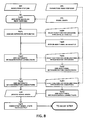
- Figures 4 to 12 show the processing operations performed by processing apparatus 2 to generate a design model in this embodiment.
- a model is generated in a 3 dimensional Euclidean space. All of the values representing coordinates are expressed relative to the global origin in the standard basis of this space.
- parameter definer 50 defines global parameters for the model.
- the backbone bases are the first objects in the model, and the global parameters defined at step S100 are also used for the generation of these bases and also some subsequent objects in the model (as will be described later).
- Figure 5 shows the processing operations performed by parameter definer 50 at step S100.
- parameter definer 50 defines the number of bases. This may be done in accordance with instructions from a user, by computing the number of bases using a mathematical function, or deriving the number of bases from a previous generation of bases.
- parameter definer 50 defines the number of backbone bases in accordance with user instructions, and in this example the number of backbone bases is defined to be 8.
- parameter definer 50 defines other global parameters. These parameters and the values assigned in this example comprise:
- reference object selector 60 selects one or more reference objects to carry the bases to be generated in the current round of processing. This is performed by selecting on or more existing reference bases and/or content objects.
- each base must have a reference base - some other base or a base that represents the orientation of a global coordinate system (global base).
- the reference base in the latter case is a virtual base - that is, each base that does not have a previously-generated base as its reference base is considered to have a global base as its reference base.
- the reference base is important in this example because all numeric quantities representing positions in space are expressed relative to the position and orientation of the reference base.
- Figure 6 shows the processing operations performed by reference object selector 60 at step S200.
- object selector 60 selects a reference coordinate system. Since backbone bases are the first bases generated in the model in this example, object selector 60 selects, by default, a reference coordinate system on this round of processing comprising the global Euclidean coordinate system 205. Although the global coordinate system (global base) is not a real object, it is shown on some figures to help the viewer with the orientation of objects on the figure.
- Figure 13a depicts the symbols used for a base in all of the following figures, wherein:
- step S220 in Figure 6 is not performed on this round of the processing.
- base generator 70 performs processing to generate the number of bases previously defined at step S110 (that is, 8 backbone bases on this round of the processing) in the coordinate system(s) of the reference object(s) selected at step S215.
- FIG. 7 shows the processing operations performed at step S300.
- the origins (positions) of the bases are computed.
- function selector 72 selects one or more mathematical functions for computing the origins of the bases in accordance with user instructions.
- position calculator 74 uses the function and parameter values selected at step S315 to calculate the origins of the backbone bases.
- Figure 13b shows the computed points P i in relation to the global coordinate system G.
- Bases are not just positions in space; each base also represents a local coordinate system at that position. Accordingly, a rotation matrix is needed for each base to be complete. This matrix defines the amount of rotation needed to rotate the coordinate axes of the reference base to the coordinate axes of the generated base.
- orientation calculator 76 defines a default orientation for each base which is then changed in accordance with user instructions. More particularly, the default orientation is the same as the orientation of the reference base (in this case global coordinate system G). This is represented with the identity rotation matrix.
- Figure 13c shows bases B i positioned on the points P i from Figure 13b with each base having the default orientation of the global coordinate system G.
- function selector 72 selects one or more mathematical functions for additional rotation of each base.
- the rotation function(s) is selected in accordance with user instructions.
- the following function is selected to compute a respective rotation matrix for each backbone base:
- R i RotationAroundAxis ⁇ 0 ⁇ 0 ⁇ 1 , i - 1 ⁇ ⁇ , i , 1 to Number of backbone bases
- Angle ⁇ 16 ⁇ ° / Number of backbone bases - 1
- This function defines the rotation of each backbone base B i as a function of the number of backbone bases and rotation angle a, so that the rotation of each backbone base will be different.
- orientation calculator 76 applies the function(s) selected at step S330 to compute a respective rotation matrix for each backbone base, thereby generating a list 340 of rotation matrices for the bases.
- base builder 78 puts together the base origins generated at step S320 and the rotation matrices generated at step S335 to define each base as a respective coordinate system comprising a position and orientation.
- Figure 13d shows the backbone bases C i positioned on points the P i from Figure 13b with applied function R[i] for their rotation.
- step S400 graph manager 80 inserts the bases generated at step S300 into a model graph and records different attributes for each base.
- FIG. 7 shows the processing operations performed by graph manager 80 at step S400.
- Figure 14a shows the state of the model graph after step S420.
- graph manager 80 assigns automatic attributes to each vertex (base) in the model graph.
- the automatic attributes comprise:
- the attribute values assigned in this example comprise: Generation: Backbone Index: 1 - 8 Name: basel - base8 Level: CENTERS Colour: 0 (white)
- Figure 14b shows the model graph after the automatic attributes have been assigned at step S425.
- step S440 at which graph manager 80 adds automatic connections between vertices representing backbone bases - referred to as intrageneration connections where "intrageneration" means between vertices representing bases from the same generation.
- CREATION ORDER there is only one automatic intrageneration connection called "CREATION ORDER”.
- This connection connects the vertices in the order in which the bases were created from first to last. Which one is first and which one last is governed by the index "i" in all of the functions used at step S300. This index always runs from 1 to the number of bases in the current generation.
- Connections are represented as edges in the model graph (that is, as pairs of vertices - actually indices of vertices). The first vertex in a pair represents the starting point of the connection and the second vertex represents the end point.
- Figure 14c shows the model graph after the processing at step S440.
- additional intrageneration connections may be added at steps S445 and S450.
- additional intrageneration connections for backbone bases, and therefore the processing at steps S445 and S450 is omitted during the current round of processing.
- steps S455, S460 and S465 automatic intergeneration connections and additional intergeneration connections may be added to the model graph.
- the generation of backbone basis is the first generation in a model, and therefore there are no intergeneration connections to be defined at this stage in the processing. Accordingly, steps S445, S460 and S465 are omitted on this round of processing.
- the model is in a consistent state.
- consistent state of the model means that all of the data from bases, content objects, and attributes and connections in the model graph are in accordance with each other (that is, there is no base or content object without the required attributes and connections).
- the designer and/or another user of the system has a chance to export the model data to other systems for the purpose of visualization, analysis, manufacturing, etc.
- data can be formatted in different ways. For example, for visualization, only the geometry and the attributes "Level” and “Colour” are needed. For structural analysis, the geometry, information about the material of content objects (contained in custom attributes - like the attribute MATERIAL described later in this example) and connections from the model graph are needed. For manufacturing, at least the geometry, the material of the content objects and their identification number (label) are needed.
- step S500 content objects can be inserted into the bases generated at step S300 in the current round.
- step S500 is omitted on this round of the processing. Step S500 is, however, performed (and described) for subsequent rounds.
- step S600 additional transformations can be applied to bases and content objects.
- This feature enables the present embodiment to change the position and/or orientation of some, or all, of the bases or some, or all, of the content objects using one or more mathematical functions without re-defining each base or content object individually.
- the backbone bases generated at step S300 are reoriented in a series of transformations by transformation controller 100.
- the processing at step S600 is provided separately in this embodiment from the processing at step S300 (at which bases were generated and orientated) and the processing at step S500 (at which content objects were generated and orientated) so that transformations can be applied taking into account both the bases and the content objects.
- one or more content objects added at step S500 may be used to compute a transformation to transform bases and/or content objects.
- Figure 10 shows the processing operations performed by transformation controller 100 at step S600.
- transformation controller 100 selects one or more functions for the transformation of bases.
- the transformation(s) are selected in accordance with instructions from a user (although they could be selected by computation).
- transformation controller 100 selects one or more parameters to be used in the function(s) selected at step S630 for the transformation of bases.
- the parameter(s) are selected in accordance with user instructions (although they could be selected by computation).
- transformation controller 100 selects one or more functions for the transformation of content objects.
- the transformation(s) are selected in accordance with user instructions (although they could be selected by computation).
- transformation controller 100 selects one or more parameters to be used in the function(s) selected at step S640 for the transformation of content objects.
- the parameter(s) are selected in accordance with user instructions (although they could be selected by computation).
- transformation controller 100 applies the transformation(s) selected at steps S630 and S640 using the parameter(s) selected at steps S635 and S645, thereby generating transformed bases and/or content objects.
- Transformation TR 1 is a transformation needed to rotate vector O 8 - O 1 to vector O v - O 1 through the point O 1 .
- Transformation TR 1 is applied only to the origins of the backbone bases B i .
- the rotation part of the bases B i is kept intact.
- B i Base [ T Bi , R Bi ]
- T Bi x i , y i , z i
- TR 1 T
- R B i ′ Base ⁇ T + R ⁇ T Bi , R Bi
- Figure 15a shows the bases B i before transformation (illustrating that the origin of base B 8 does not lie directly over the origin of base B 1 ) and the bases B i '' after transformation controller 100 has applied transformation TR 1 and correction to their z coordinates (illustrating that the origin of base B 8 '' now lies directly over the origin of base B 1 '').
- Rotation R 1 is defined as rotation around global Y-axis ⁇ 0, 1, 0 ⁇ for 180 degrees:
- a rotation R 2 is applied locally - that is, only on the rotation part of each backbone base B i '''. This is meant to bring the X-axis of each backbone base to point again in the direction it had before application of the global rotation R 1 .
- step S700 content generator 90 can add new content objects to the model, and at step S800, graph manager 80 can perform processing to update the model graph.
- steps S700 and S800 are not performed during the current round of processing. More particularly, because no new content objects are to be defined and all of the attributes and connections have already been established at step S400, then steps S700 and S800 are not necessary.
- the model is in a consistent state, and therefore data can be exported to one or more other systems, as described previously with reference to step S475.
- step S900 a check is performed to determine whether another generation of bases is to be added to the model.
- the backbone bases comprise the first generation of bases, and further generations of bases are to be added. Accordingly, processing returns to step S100 for the next round of processing, which will be described below.
- Second Round of Processing Generating Ring Bases (Second Generation Bases) With Content Objects
- the second generation of bases in the present example is a generation of "ring" bases.
- Each backbone base serves as a reference base for a specific number of ring bases to be arranged in a ring on a plane around the backbone base.
- the ring bases are generated by performing a second round of the processing in Figure 4 , as will now be described.
- parameter definer 50 defines the number of bases for this generation of bases in accordance with user instructions.
- the number is 18 new bases for each backbone base. This number is the same for each backbone base, but it could be a different number for each backbone base.
- parameter definer 50 defines a value for a specific global parameter comprising the depth of white blocks.
- the parameter "depth of white blocks" is used at step S700 for the creation of content objects.
- the parameter "depth of white blocks" is set to the value 1.0.
- reference object selector 60 selects reference bases for the new ring bases.
- each backbone base is chosen as a reference base for 18 respective ring bases.
- the first backbone base serves as a reference base for the first 18 ring bases
- the second backbone base serves as a reference base for the next 18 ring bases
- so on up to the last backbone base which serves as a reference base for the last 18 ring bases.
- I ref index of reference backbone base
- I ref [ I ] Quotient I - 1 , number of base per ring + 1
- base generator 70 generates the ring bases.
- the number of ring bases is equal to the number of bases defined at step S110 in this round of processing (that is, 144).
- steps S315 and S320 the origins of the bases are computed.
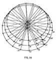
- the procedure for computing the origin of each ring base in the present example will be described with reference to Figure 16 .
- the origins of its 18 ring bases are positioned on a circle with a specific radius in the XY plane of the backbone base.
- the origins are equidistantly spaced around the perimeter of the circle, with the first origin at 0° angle and the others following in the counter-clockwise direction.
- the positions of the origins of the ring bases are computed as if they all lie in an XY plane with the global coordinate system as a local coordinate system. After that each ring base is transformed with appropriate transformation to lie in the same position relative to its reference base (backbone base) as it is in the global coordinate system.
- I ref [I] is a variable of the function - that is, the radius of the circle upon which the origins of the ring bases lie is dependent upon the index I of the reference base (the backbone base to which the ring bases belong).
- the radius changes as the index I changes, so that the radius is different for each backbone base.
- the radius R1 of the circle of ring bases 1-18 is different from the radius R2 of the circle of ring bases 19-36 and the radius R3 of the circle of ring bases 37-54.
- This feature of the present embodiment enables variations in the ring bases to be introduced throughout the model without having to define the ring bases individually. This is particularly advantageous where a large number of ring bases are to be defined for the model.
- the form and extent of this variation is set in accordance with the mathematical function having the index of the backbone base as a variable.
- each origin O i must be transformed with a transformation TB[I] which is in reality a defining transformation of the ring base's reference backbone base C[I ref [I]].
- TB I Transformation C I ref I
- Figure 17 shows the global positions of the origins O i of the ring bases computed by position calculator 74 in accordance with the equations above.
- C i are the reference backbone bases.
- the origins of the backbone bases are computed locally to their reference base and then transformed to the global coordinate system. They could instead be defined directly in the global coordinate system, but the functions used would be more complex. On the other hand, a situation can be foreseen where functions for computing the origins of the bases directly in the global coordinate system would be less complex than computing them locally (i.e., when there is no dimensional relation to the reference bases).
- function selector 72 selects one or more functions for additional rotation of the ring bases.
- a function is selected to rotate the Z-axis of each ring base so that the Z-axis points to the origin of the ring base on the next ring which is expressed with the following relation on the ring base indices:
- each ring base B Ri should lie in the plane P that goes through the origins O 1 , O 2 and C (that is, the origins of ring base B Ri , ring base B R [I TO ] and reference backbone base C[I ref ]).
- the amount of rotation R i needed is calculated from the directed angle ⁇ between the X-axis of base B Ri ' and the plane P.
- Figure 19b shows the final ring bases B Ri '' after applying transformation TR i and rotation R i .
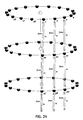
- graph manager 80 inserts the ring bases generated at step S300 into the model graph and records different attributes and connections for each ring base.
- FIG. 20 shows the model graph after the processing at step 420.
- Automatic attributes are assigned to each vertex (base) by graph manager 80 at step S425.
- the automatic attributes are: Generation: Rings Index: 1 - 144 Name: base 1 - base 144 Level: RINGS Colour: 0 (white)
- Ring bases are organized in rings. Within each ring, the ring bases are characterized by the fact that they have the same reference backbone base. Backbone bases are numbered from 1 onward and the index of each backbone base in the generation "backbone” can therefore be considered as a ring number. Additional attributes can be arbitrary, and thus their values may be defined through the use of functions. For the attribute "ring number”, the function previously defined at step S215 in this round of processing is used, which is a function for calculating the index of the reference backbone base I ref from the index of ring bases.
- graph manager 80 adds the automatic connection called "CREATION ORDER" between the vertices representing ring bases.
- this connection defines the order in which the vertices were created from first to last.
- the resulting model graph is shown in Figure 22 , in which the arrows show the creation order.
- Additional intrageneration connections are selected and defined in steps 445 and S450. They facilitate the use of the ring bases as parameters in functions and procedures later on in the course of the example. In the present example, four additional connections are defined:
- Indices of pairs are relative indices in the set of ring bases.
- graph manager 80 adds automatic intergeneration connections.
- An intergeneration connection is a connection that connects bases in different generations (a new base generated in the current round of processing and an existing base generated in a previous round of processing).
- a connection called "SUBBASES” is added automatically from each backbone base to every ring base that counts this backbone base as its reference base.
- the formula for edges is:
- the first index in a pair refers to the backbone bases and the second index refers to the ring bases. Part of the resulting model graph is shown in Figure 25 .
- the model is in a consistent state; therefore its data can be exported to other systems for various purposes, as described previously.
- step S500 in the present example content generator 90 inserts a content object into each ring base generated at step S300. More particularly, in this example, a point P is inserted into each ring base in the same position relative to the ring base's origin as its position to the global coordinate system G. This relationship is shown in Figure 26a .
- Point P is the same for each ring base, and comprises an example of a primary content object.
- the content object (point P) in this example is inserted into every ring base, this need not be the case, and instead the content object may be omitted from one or more ring bases.
- the content object inserted into each ring base is the same content object in this example, different content objects could be inserted into different ring bases.
- FIG. 9 shows the processing operations performed by content generator 90 at step S500.
- step S505 content importer 92 selects the external content object to be imported and its source.
- these processes are performed in accordance with user instructions (although they could be performed automatically by computation).
- step S515 content importer 92 imports the selected content object into the system, and assigns a copy of the content object (in this case point P) to each ring base generated at step S300.
- the points P are the first content objects in the model of the present example. Their type is POINT and their data consist of x, y and z coordinates. Each ring base B Ri gets its own copy of point P. This is shown in Figure 26b .
- step S530 graph manager 80 adds each content object assigned at step S525 as a new vertex to the model graph. This is performed in a similar way to the addition of a vertex for each base at step S420 (described previously).
- Figure 27 shows a part of the model graph after step S530.
- step S535 graph manager 80 assigns the following automatic attributes to each vertex in the model graph representing a point P: Index: 1 - 144 Name: bpoint Level: BPOINT Colour: 0 (white)
- the combination of the attributes "index” and "name” (or the combination "index” and “level”) comprise a unique content object identifier, from which each contact object can be uniquely identified.
- Figure 28 shows part of the model graph after step S535.
- step S555 graph manager 80 adds CONTENT connections to the model graph for the content objects assigned at step S525. More particularly, each point P has a reference ring base. The automatic connection called "CONTENT" is added to the model graph to show this relation for each ring base and its point. Part of the resulting model graph is shown in Figure 29 .
- step S500 the model is in a consistent state, and therefore at step S575 its data can be exported to other systems for various purposes, as described previously.
- step S600 no processing is required at step S600, and therefore this step is omitted on this round of processing.
- content generator 90 creates new content objects for the model using one or more mathematical operations.
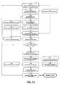
- FIG 11 shows the processing operations performed by content generator 90 at step S700.
- a solid block (mesh) is inserted into each ring base.
- auxiliary objects are created.
- Six planes are sufficient to fully bound a solid block of the proposed shape, and a line is calculated to define two of the planes.
- Each content object is created in every ring base according to the same procedure.
- steps S705 to S799 are executed 8 times in sequence (a line, 6 planes and a mesh), the description of these steps is made for all of the created content objects together.
- step S705 content creator 94 selects the type of each new content object.
- the selection is performed in accordance with user instructions (although it could be performed automatically).
- the object types are LINE, PLANE and MESH. Lines and planes are primary content objects, while mesh is in the category of solid content objects.
- content creator 94 selects operations for the creation of the content object, the bases in which the content object is to be generated and parameters for the creation operations, respectively, with the selected operation parameters being recorded at step S740. In this embodiment, these selections are performed in accordance with user instructions, although they could be performed automatically.
- step S745 content creator 94 executes the operations selected at step S715 in accordance with the bases and parameters selected at steps S720 and S730 to generate the same new content object(s) in all of the bases selected at step S720. For every new content object, the same generating procedure is executed in all of the selected bases. This assures that if a procedure for creation of a new content object is composed with actual data from a single base, it can be replicated without change to all the selected bases in the generation.
- the values of actual parameters may be different for every base, but their composition (number and types of parameters) is the same.
- Object name Description of creation function: Bisector Angle bisector between two directions from a given point in space. Left plane, Right plane Oriented plane through line and point Down plane, Top plane Oriented plane through three points Front plane "Closest” oriented plane from 4 points (used method of least squares to calculate closest plane) Back plane Moved and inverted plane White block Mesh from oriented planes
- Figure 30a shows the construction of an angle bisector L in ring base B Ri .
- Line L lies in a plane defined by points O, ON and O P and bisects the angle between points OP - O - ON.
- O end ⁇ O start > ⁇ ⁇ edge 1> [ ⁇ ⁇ edge 2> ⁇ ... ⁇ ⁇ edge N> [ ⁇ attribute value> ⁇ ]] shows selection of object O end by following the connections in the model graph from object O start to the object to which connection ⁇ edge 1> points, from there to the object to which connection ⁇ edge 2> points, and so on to the last object to which connection ⁇ edge N> points. Since many connections (e.g., "SUBBASES", "CONTENT") can have more than one value on the same object, a qualifier ( ⁇ attribute value>) has to be specified to select a particular object.
- B Ri ⁇ NEXT points to an object which can be selected by following connection NEXT from object (base) B Ri . Since this connection has only one value, no qualifiers are needed. From the definition of the connection NEXT in step 400, the object at the end of it is ring base B Ri+1 .
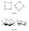
- Figures 30b, 30c and 30d show the construction of a plane from 4 points using 3 different subsets of 3 defining points. With four points (O, O N , O NT , O T ) and one of them fixed (O), only three possible combinations of three different points are possible: (O, O N , O NT ), (O, O N , O T ) and (O, O T , O NT ,). For each triplet, a different plane can be constructed. These three different planes are depicted in Figures 30b, 30c and 30d , respectively.
- Figures 31a and 31b show created content objects in two consecutive ring bases.
- the labels used in these figures depict the same objects as the labels in Figures 30a-30d with the following additions:
- Lines L i , L N and L NN are constructed by the procedure illustrated in Figure 30a in bases B Ri , B N and B NN respectively.
- Plane P L is constructed from line L i and point O T .
- Line L i is represented with two points; therefore the plane can be constructed from a line and an additional point.
- the plane's normal vector lies in the same halfspace as the point O P .
- Plane P R is constructed from line L N and point O NT .
- the plane's normal vector lies in the same halfspace as the point O NN .
- Plane P D is constructed from three points O PT , O T and O NT .
- the plane's normal vector lies in the opposite halfspace as the point O.
- Plane P T is constructed from three points O P , O and O N .
- the plane's normal vector lies in the opposite halfspace as the point O T .
- Plane P F is constructed from three points O, O N and O T .
- the plane's normal vector lies in the opposite halfspace as the point O + X-axis [B Ri ].
- Plane P B is inverted plane P F , moved for distance d in the direction of the normal vector of plane P B .
- Solid block W i is a mesh constructed from planes P L , P R , P D , P T , P F , P B . Each plane divides a space into two halfspaces and one of them can be considered full. By convention, the halfspace in which the normal vector of the plane points is considered empty, the other half as solid. Solid block W i is then constructed as an intersection of six planes. The normal vectors of the six bounding planes are oriented in such a way that they point outwards of the resulting solid block.
- each content object is generated in accordance with a procedure comprising a series of steps using at least one mathematical function. Furthermore, the procedure for the generation of each content object is dependent upon a plurality of ring bases (even though the content object is defined in the local coordinate system of only one base). Accordingly, because the arrangement of ring bases varies throughout the model (because the ring bases were defined so that they vary in accordance with the identity of the backbone base to which they belong), then the content objects also vary throughout the model in accordance with the variations of the ring bases. However, it should be noted that the present embodiment does not provide a separate definition of each content object in order to achieve this variation - instead, a single definition is provided using at least one mathematical function and a plurality of bases.
- the system will automatically regenerate the content objects in accordance with the definition using the new arrangement of bases and the mathematical function(s) for the definition of the content objects. As a result, the system adapts the content objects to any change in the bases.
- new content objects are not created in all ring bases. More particularly, the definition of planes and white block depends on the data of the ring bases from two consecutive rings. However, each base on the last ring has no TO connection, meaning that there are no more ring bases.
- Figure 31b shows the final solid blocks W i and W N , belonging to ring bases B Ri and B N respectively.
- Block W N is rendered in cross-section.
- content objects also keep information on object type, selected creation function(s) and references to the bases and/or objects that serve as parameters for the creation function(s).
- object "White block” Wi stores following non-geometric data:
- Object type Mesh Geometric modelling kernel: OpenCASCADE Creation function: Mesh from oriented planes (from OpenCASCADE) Pointers to reference objects: Base B Ri Planes P L , P R , P D , P T , P F , P B Values of reference parameters: Numeric parameter d
- Representation of a content object with operation and references to parameter objects for an operation enables the system to keep track of the history of a content object.
- the system can revaluate the object anytime, possibly with altered source object parameters.
- each content object After the creation of each content object, its validity is checked by content creator 94 at steps S750 and S755.
- This processing is performed in this embodiment because not all combinations of input data can produce valid objects. For example, a line is defined with two distinct points. If the points are the same, then the line is not defined properly, it is not valid, and cannot be used in other operations.
- Each type of object has its own set of criteria that must be satisfied for successful validation. Simple objects like points, lines, planes, can be easily checked. More complex ones like meshes and other solid objects may need special functions to be properly checked. In this embodiment, these functions are provided by the geometric modelling kernel used for computing the solid objects and are executed automatically (that is, the creation function fails if the resulting object is not properly formed). In the event that a validation function is not provided automatically, the present embodiment allows for a validation function to be selected by content creator 94 at step S750 in accordance with user instructions.
- graph manager 80 adds the object as a new vertex to the model graph at step S765.
- Figure 32 shows part of the model graph with new vertices for the content objects in ring bases with indices I, I + 1 and I + 18.
- graph manager 80 assigns automatic attributes to each new vertex in the model graph representing a new content object.
- the automatic attributes assigned by graph manager 80 to a content object comprise: Index Name Level Colour I Bisector BISECTOR 0 I Left plane PL-LEFT 0 I Right plane PL-RIGHT 0 I Down plane PL-DOWN 0 I Top plane PL-TOP 0 I Front plane PL-FRONT 0 I Back plane PL-BACK 0 I White block BLOCK 0
- step S775 graph manager 80 selects any additional attributes to be added for a content object in accordance with user instructions, and at step S780, adds the additional attribute(s) to the model graph.
- Figure 33 shows the same part of the model graph as Figure 32 with the attributes added at steps S770 and S780 for the present example.
- step S790 graph manager 80 adds a CONTENT connection to the model graph for each new content object.
- each new content object has a reference ring base. Accordingly, at step S790, the automatic connection called "CONTENT" is added to the model graph to show this relation between the reference ring base and the new content object. Part of the resulting model graph is shown in Figure 34 .
- step S700 the model is in a consistent state, and therefore at step S799 its data can be exported to other systems for various purposes, as described previously.
- Step S800 is the last step in the generation of ring bases.
- sensor function executer 110 generates and executes one or more so-called sensor functions to test a property of the bases or content objects and to divide the bases or content objects into equivalence classes in dependence upon the results of this test.
- sensor function executer 110 classifies bases into two equivalence classes. As will be described later, the system subsequently generates content objects such that the content objects depend upon the equivalence class to which their reference base belongs.
- FIG. 12 shows the processing operations performed at step S800.
- sensor function executer 110 defines one or more attribute(s) and/or one or more connection(s) on which a sensor function is to operate. More particularly, sensor function executer 110 may select an existing attribute or connection or instead may define a new attribute or connection.
- the new attribute "CURVATURE” is added to each ring base.
- This attribute may take one of two possible values, "+” and "-” (which is calculated later), such that bases with "+” CURVATURE fall within one equivalence class and bases with "-” CURVATURE fall within another equivalence class.
- sensor function executer 110 defines a sensor function, Sensor [I], to be used in calculating values of the attribute(s) and/or connection(s) defined at step S805. If an existing attribute or connection is selected at step S805 which already has stored values, then step S830 is omitted.
- sensor function executer 110 selects criteria data to be applied to values computed using the sensor function Sensor [I] in order to divide the bases/content objects into equivalence classes.
- CURVATURE I ⁇ - , Sensor I ⁇ 0 + , Sensor I ⁇ 0
- the sensor function Sensor [I] and the criteria data define values of the attribute CURVATURE which represent the curvature of the surface of the model in the vicinity of a ring base. If the curvature in the vertical direction in the immediate vicinity of a ring base is convex, then the CURVATURE value is "+" for that ring base. On the other hand if the curvature is concave, the value is "-".
- sensor function executer 110 selects objects to which the sensor function Sensor [I] and criteria data are to be applied.
- sensor function executer 110 applies the sensor function Sensor [I] to the selected objects and determines the value of the attribute CURVATURE for each object in accordance with the sensor function value and the criteria data selected at step S835.
- Figures 35a, 35b and 35c show the distribution of these two equivalence classes over the model of the present example. To better see the difference between the convex and concave curvatures, the white blocks generated in step 700 are shaded differently according to the value of attribute "CURVATURE". Figures 35b and 35c show only blocks in ring bases having a value of the attribute CURVATURE "+" and "-" respectively.
- graph manager 80 adds the attribute(s) and calculated value(s) therefor to the model graph.
- Figure 36 shows part of the model graph with the values of the attribute "CURVATURE" assigned to the vertices representing ring bases.
- the generator is in a consistent state, and therefore its data can be exported to other systems for various purposes at step S855, as described previously.
- the generation of ring bases is the second generation of bases in the example model.
- the generation of centre bases comes next, and therefore processing returns to step S100 for another round of processing to add these bases.
- the third and last generation of bases in the present example is a generation of centre bases.
- each ring base on all but the last ring serves as a reference base for a single centre base.
- parameter definer 50 defines the number of bases for this generation of bases in accordance with instructions from the user.
- the number of bases is the only initial global parameter for this generation of bases in the present example, and therefore the processing at step S115 is omitted.
- reference object selector 60 selects reference bases for the new centre bases.
- each of the ring bases with index 1 to 126 are chosen as a reference base for a single centre base.
- reference object selector 60 selects existing objects to be used for the definition of the centre bases.
- Bases ring bases
- Content objects (all from ring bases): bpoint Left plane Right plane Top plane Down plane
- base generator 70 constructs the centre bases.
- the origins of the bases are computed at steps S315 and S320. More particularly, for the present example, the following procedure is selected for computation of the base origins:
- Neighbouring bases are defined as bases following connections in the model graph labelled NEXT, TO and NEXT ⁇ TO from base B Ri .
- each centre base is dependent upon two existing bases (the origins O Ri and OT belonging to these bases) and two existing content objects (the points P N and P NT ).
- Figure 37a shows points from the definition above.
- centre base C i is the same as the orientation of its reference ring base B Ri . This situation is shown in Figure 37b .
- a first rotation rotates the X-axis of the centre base C i around its Z-axis in such a way that it points in the direction of a vector from point O Ri to point P N .
- the functions for this rotation are therefore:
- the rotation R i is applied locally, that is, only on the rotation part of base C i .
- a second rotation orients the Z-axis of the centre base C i vertically, as shown in Figure 37d .
- This rotation is given by:
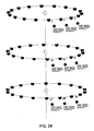
- Figure 38 shows final centre bases C i '' after applying rotation R i and transformation TR i .
- Step S400 graph manager 80 inserts vertices representing the centre bases into the model graph.
- FIG. 39a shows part of the model graph after the processing at step S420.
- New vertices for the centre bases are shown in the ring bases with indices I, I + 1, I + 18 and I + 19. These centre bases have indices J, J + 1, J + 18 and J + 19 respectively.
- Indices I and J run from 1 to number of centre bases.
- graph manager 80 assigns automatic attributes for the centre bases.
- the automatic attributes comprise: Generation: Centers Index: 1 - 126 Name: centerbase Level: BCENTERS Colour: 0 (white)
- the combination of the attributes "Generation” and “Index” comprise a unique identifier for each centre base.
- Figure 39b shows the same part of the model graph as Figure 39a with the automatic attributes added for the centre bases.
- step S440 graph manager 80 adds the automatic intrageneration connection "CREATION ORDER" (described previously) between the vertices of the model graph representing the centre bases. Part of the resulting model graph is shown in Figure 40 .
- graph manager 80 adds automatic intergeneration connections.
- the connection called "SUBBASES” is added automatically from each ring base to the centre base that has this ring base as its reference base.
- the formula for edges is:
- the first index in a pair refers to the ring bases and the second index refers to the centre bases. Part of the resulting model graph is shown in Figure 39c .
- the generator is in a consistent state, and therefore its data can be exported to other systems for various purposes at step S475.
- step S500 content generator 90 inserts content objects into each centre base generated at step S300.
- an invariant polygon F and points P L , P R , P B and P T are inserted into each centre base at the same positions relative to the base's origin as their positions relative to the global coordinate system G. This relationship is shown in perspective view in Figure 41a .
- content importer 92 performs processing at steps S505, S515 and S525 to import the polygon F and the points P L , P R , P B and P T into the system and assign a copy of each imported polygon and point to each centre base.
- Polygon F is a primary content object.
- the polygon is created in an outside CAD system and its coordinates are then transferred to the system through a plain ASCII file.
- Each centre base C i gets its own copy of these content objects at step S525. This situation is shown in perspective view in Figure 41b .
- graph manager 80 inserts vertices corresponding to the new content objects into the model graph. For each added content object in each centre base, a new vertex is inserted into the model graph. This means that a total of 630 new vertices are added (126 centre bases times 5 content objects).
- Figure 42a shows part of the model graph with added vertices.
- graph manager 80 assigns the following automatic attributes to each new vertex: Index Name Level Colour I Invariant INVARIANT 0 I pleft POUT 0 I pright POUT 0 I pbottom POUT 0 I ptop POUT 0
- Figure 42b shows the same part of the model graph as Figure 42a with added automatic attributes for the content objects.
- step S555 graph manager 80 assigns a CONTENT connection (as described previously) to each content object.
- Each content object has a reference centre base.
- the automatic connection called "CONTENT" is added to the model graph to show this relationship between each centre base and each of the 5 imported content objects for that centre base. Part of the resulting model graph is shown in Figure 42c .
- the model is in a consistent state, and therefore its data can be exported to other systems for various purposes at step S575.
- transformation controller 100 applies additional transformations to the points P L , P R , P B and P T imported at step S500, while keeping the centre bases C i unchanged.
- transformation controller 110 selects functions for transforming each of the points P L , P R , P B and P T at step S640 and selects parameters for the functions at step S645 before applying transformations in accordance with the selected functions and parameters at step S650.
- transformations for each point P L , P R , P B and P T are computed by functions dependent upon the index of the reference centre base for the point. The functions differ from point to point in parameters only. The definition of the transformation function will be explained with reference to Figure 43a .
- the parameters r, ⁇ s and ⁇ are different for each point P L , P R , P B and P T .
- the centre of circle A is computed from each point by adding a displacement vector d which is also different for each point.
- the parameters selected at step S635 are: Point D r ⁇ s ⁇ P L ⁇ 0, -2, 0 ⁇ 1.7 0° 45° P R ⁇ 0, -2, 0 ⁇ 1.7 0° 45° P B ⁇ 0, -2, 0 ⁇ 1.7 90° 45° P T ⁇ 0, -2, 0 ⁇ 1.7 90° 45°
- the polygon F and points P LT , P RT , P BT and P TT have a final form which is different depending upon whether their reference ring base B Ri has a "+" ve CURVATURE or a "-" ve CURVATURE.
- the final form of the polygons and points (content objects) is dependent upon the equivalence class of their reference base previously determined at step S800 in the second round of processing.
- Figure 43b shows the transformed and mirrored content objects in base C j after transform controller 100 has applied the transformations above at step S650.
- step S700 The next (and final) step in this round of the processing, and consequently in this example, is step S700.
- content generator 90 generates further content objects for the model.
- the content object to be added in this step is a solid block (mesh) inserted into each centre base.
- Six planes as auxiliary objects are used for its creation. This solid block is at the end trimmed with some of the planes created at step 700 during the second round of the processing (that is, the round to generate the ring bases).
- Each new content object is created in each centre base according to the same procedure.
- step S705 content creator 94 selects the type of each new object.
- the object types for the new objects are PLANE and MESH.
- content creator 94 selects the operation(s) for the creation of each new content object, the bases in which the content object is to be generated, and parameters for the operation(s) respectively, with the parameters then being recorded at step S740.
- Object name Description of creation function: All planes Oriented plane through three points BIL Mesh from oriented planes BIL cut Cut mesh with oriented plane
- the functions "Oriented plane through three points” and “Mesh from oriented planes” were described previously with reference to step S700 in the second round of processing.
- the function "Cut mesh with oriented plane” is a function that performs a difference operation between a solid object represented as a mesh and a solid halfspace defined with a plane.
- the positions of the points P LTi , P RTi , P BTi and P TTi were calculated at step S650 using a function dependent upon the index of the reference base in which the points lie. Accordingly, by using these points to generate content objects in this step, the content objects themselves are also dependent upon the reference base indexes.
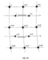
- Figure 44b shows the definition of the auxiliary planes L, R, D, T, P and B. All of them are defined by three points.
- the points F i represent the vertices of the polygon F.
- Plane L is constructed from three points P LTi , F 1 and F 4 .
- the plane's normal vector lies in the opposite halfspace to the point F 2 .
- Plane R is constructed from three points P RTi , F 2 and F 3 .
- the plane's normal vector lies in the opposite halfspace to the point F 1 .
- Plane D is constructed from three points P BTi , F 1 and F 2 .
- the plane's normal vector lies in the opposite halfspace to the point F 3 .
- Plane T is constructed from three points P TTi , F 3 and F 4 .
- the plane's normal vector lies in the opposite halfspace to the point F 1 .
- Plane B is constructed from three points F 1 , F 2 and F 3 .
- the plane's normal vector lies in the opposite halfspace to the point P LTi .
- Plane P is constructed from three points P LTi , P BTi and P RTi .
- the plane's normal vector lies in the opposite halfspace to the point F 1 .
- Figure 44c shows different planes R versus R' and D versus D' constructed from different positions of points P RTi v. P RTj and P BTi v. P BTj .
- Points P RTj and P BTj came from different centre bases C j and represent the change imposed by the transformation functions from step 600 when the index of centre base changes from i to j.
- Figure 44d shows the final solid block S i , belonging to centre base C i .
- Solid block S i is a mesh constructed from the intersection of the six planes L, R, D, T, P and B.
- the last operation in this example trims the solid block Si with planes from ring base B Ri , which is a reference base for centre base C i , which in turn holds solid block Si.
- the resulting solid block S C is constructed from solid S i by subtracting inverted planes P L , P R , P D , P T from it. This step assures that the final solid block S C fits into the space bound by the solid block W, which was constructed at step S700 in the second round of processing. This assurance comes from the fact that the same planes are used in the construction of solid blocks W and S C .
- step S745 After the creation of each object at step S745, its validity is checked at step S755.
- step S755 In this step of the present example, the following validation checks are performed:
- step S765 graph manager 80 adds new vertices to the model graph corresponding to the new objects created at step S745.
- new vertices are inserted into the model graph.
- Figure 45a shows part of the model graph with the new vertices for the content objects in two consecutive centre bases.
- graph manager 80 assigns the following automatic attributes to each vertex representing a new content object: Index Name Level Colour I Left plane BIL-LEFT 0 I Right plane BIL-RIGHT 0 I Down plane BIL-DOWN 0 I Top plane BIL-TOP 0 I Front plane BIL-FRONT 0 I Back plane BIL-BACK 0 I BIL BIL 2 I BIL cut BIL-CUT 2
- graph manager 80 assigns an additional attribute for the objects BIL and "BIL cut” called “Material".
- this attribute has the same value for all objects: GLASS
- Figure 45b shows the same part of the model graph as Figure 45a with the attributes added for the content objects.
- Each new content object has a reference centre base.
- graph manager 80 adds the automatic connection called "CONTENT" to the model graph to show the relationship between each centre base and its new content object. Part of the resulting model graph is shown in Figure 45c .
- step S800 is not necessary in the current round of processing. This is because the content objects created at step S700 are the last objects constructed in the present example, and therefore no additional attributes or connections to bases or objects in the model are needed.
- the generation of the centre bases is the last generation of bases in this example.
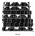
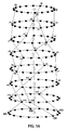
- Figure 46 shows the resulting model after completion of all of the steps in the three rounds of processing.
- the ring bases, centre bases and solid objects named BIL are shown.
- the resulting model is clearly divided into two distinct regions A and B, which correspond to the partition of the ring bases into two equivalence classes based upon the attribute "CURVATURE" defined at step S800 in the second round of processing (refer to Figure 35a ).
- Region A is based on the ring bases with positive curvature and region B on the ring bases with negative curvature.
- Objects in region A have their tips pointing outwards, while objects in region B have their tips pointing inward.
- the relative position of their tips against the backplane of the object (made from polygon F; refer to the description of steps S500 and S700 in this round of processing) follow a distinct sinusoidal pattern. This effect is the result of the parameters used to position the points P LT , P RT , P BT and P TT (described at step S600 in the third round of processing and shown in Figures 43a and 43b ).
- the influence of the backbone bases can also be seen on the right edge of region B. If the backbone bases were vertically aligned on top of each other, the edge of the region B would be linear (albeit not vertical, because the radius of the ring bases also changes from ring to ring; increasing from 12 m on the top (first) ring to 15 m on the bottom (last) ring).
- the present embodiment stores all of the mathematical functions, mathematical procedures and parameter values used to produce the bases and content objects in the model.
- the embodiment allows the user to access the stored functions, procedures and parameter values, and to amend them to change the generated model.
- the system In response to the user amending a function, procedure and/or parameter value, the system automatically regenerates the bases and/or content objects in accordance with the amendments and any unamended functions, procedures and parameter values. As a result, the effect of changes can be quickly seen by the user.
- the value of a parameter in the equations used to generate the backbone bases at step S300 in the first round of the processing is changed.
- parameter F (defined with reference to step S300 in the description of the first round of processing) is changed from 0.75 to 3.0.
- the points P L , P R , P B , P T inserted into the centre bases were transformed into points P LT , P RT , P BT , P TT according to a set of parameters (for detailed description of the transformation see the description of step S600 in the third round of processing).
- the value of the parameters ⁇ L , ⁇ R , ⁇ B and ⁇ T used to transform the points is changed from 45° to 120° (all of the parameters have the same value).
- the result of changing the parameters F, ⁇ L , ⁇ R , ⁇ B and ⁇ T in this way is shown in Figure 48 .
- the arrangement of regions A and B is the same as in Figure 47 .
- the difference is in the directions in which the tips of the solid objects named BIL point.
- the objects labelled BIL I , BIL II and BIL III in Figure 48 have their tips pointing in the opposite direction to the objects with the same labels in Figure 47 .
- These objects are respectively created in the centre bases with the same indices in the model from example 1 and in the model from example 2 (object BIL I is created in a centre base with index I in both models; the analogue statement is true for objects BIL II and BIL III ).
- the points P L , P R , P B , P T inserted into the centre bases were transformed into points P LT , P RT , P BT , P TT according to a set of parameters.
- the values for these parameters are changed to: Point D r ⁇ s ⁇ P L ⁇ -0.35, -2, 0 ⁇ 1.0 0° 22.5° P R ⁇ 0.35, -2, 0 ⁇ 1.0 0° 45° P B ⁇ 0, -2, -0.35 ⁇ 1.0 90° 90° P T ⁇ 0, -2, 0.35 ⁇ 1.0 90° 180°
- FIG. 49 the arrangement of regions A and B is the same as in Figure 47 . The difference is in the size and directions in which the tips of the solid objects named BIL point.
- Figure 49 shows that the objects labelled BIL I , BIL II , BIL III , BIL IV , and BIL V have tips of different shapes and sizes.
- a fourth example will now be described, in which a function used to generate some of the bases is changed. More particularly, an example will be described in which the function R[I] used at step S300 in the second round of processing to calculate the radii of the circles upon which the ring bases lie is changed.
- a more versatile function Sine is used to compute the radii of the ring bases.
- the radius of I-th ring base R[I] is adjusted by the value of the Sine function at each floor. The radii thus oscillate around the fixed radius R fixed .
- the parameter "NumberOfBackboneBases” was defined at step S110 in the first round of processing (generation of backbone bases).
- the parameter "arg” defines the number of full sine waves produced from the top to bottom floors. In this example, one and a quarter waves are applied from top to bottom.
- the system automatically reapplies the changed function and all previously defined functions and parameters to regenerate the model.
- the user can change some of the bases (the ring bases in the present example) and the system automatically regenerates all bases and content dependent thereon.
- the ring bases, centre bases and solid objects named BIL are shown.
- the main difference is in the arrangement of regions A and B, which correspond to the equivalence classes based upon the attribute "CURVATURE".
- the Sine function introduces a bulge in the upper part of the model and a valley in the lower part, and therefore the distribution of regions A and B is clearly different from Figure 46 .
- the influence of a quarter of the next sine wave can also be seen in the bottom right part of the figure.
- the reason why not all of the bottom line belongs to region B is the influence of the positions of the backbone bases.
- content objects were inserted into the bases such that the content object was the same for every base at the time of insertion.
- processing can be performed by the system to insert content objects so that a property of each content object (such as its position, orientation and/or shape) varies in accordance with the base into which the content object is inserted.
- step S500 in the third round of processing 5 content objects were inserted into each centre base. More particularly, four points P L , P R , P B , P T and a polygon F were brought into the system from an outside source and a copy of each object was assigned to each centre base. As a result, polygon F was identical for each centre base.
- step S500 may be performed instead so that a property of polygon F changes in dependence upon the centre base into which it is assigned.
- Figures 51a and 51b show the starting shape of the polygon F S and the ending shape of the polygon F E , respectively. Also shown are points P L , P R , P B , P T , which are the same for each centre base. All objects are shown in the same position relative to the centre base's origin as their position to the global coordinate system G.
- the coordinates of the vertices of the polygon are:
- the coordinates of the points P L , P R , P B , P T are the same as those used at step S500 of the third round of processing.
- Content importer 92 inserts starting polygon F S into the first centre base (i.e., into centre base with index 1 that belongs to the first ring base) and inserts ending polygon F E into the last centre base. All centre bases in between receive a differently shaped polygon F i .
- These polygons are computed by content generator 90 by the use of a mapping function M:
- V i1 , V i2 , V i3 , V i4 of the polygon F i are computed as follows:
- the mapping function M can be used for computation of intermediate objects for any pair of objects that can be represented solely by the same number of vertices.
- Figure 52 shows polygons F i and points P L , P R , P B , P T distributed to the centre bases Ci.
- Figure 53 corresponds to the view of the model from Figure 46 .
- the difference between the models shown in Figure 53 and Figure 46 is clear. Even on the top row, where the differences between the actual polygons F used for the creation of the solid objects BIL are small, the solid objects have already started to rotate. This rotation is brought about by the rotation of the top edge of polygon F.
- the changing of the polygon F from rectangular to triangular shape also influences the slant of the side planes that govern the creation of solid objects (see the description of step S700 in the third round of processing). This change can be so big that the small front plane on the tip completely disappears and becomes an edge, like on objects BIL I and BIL II .
- the present embodiment provides facilities for a designer to use to ensure that content objects fit together without gaps and without encroaching upon each other (that is, two content objects do not occupy the same space).
- content creator 94 provides means for a user to define functions for the creation of a content object such that, as part of the creation, the right side of the content in a base and the left side of the content in the next base (or vice versa) are cut with the same plane.
- mapping function M is used to change the shape of polygon F.
- the same mapping function is used in this example, but the difference is in the start and end polygons F S and F E respectively. These polygons are shown in Figure 54a and have vertex coordinates.
- the parameters that are also adjusted for this example govern the creation of the backbone bases (see step S300 in the first round of processing) and the transformation of points P L , P R , P B , P T into points P LT , P RT , P BT , P TT (see step S600 in the third round of processing).
- Parameter F 3.0. Point D r ⁇ s ⁇ P L ⁇ -0.35, -2, 0 ⁇ 0.5 0° 22.5° P R ⁇ 0.35, -2, 0 ⁇ 0.5 0° 45° P B ⁇ 0, -2, -0.35 ⁇ 0.5 90° 90° P T ⁇ 0, -2, 0.35 ⁇ 0.5 90° 180°
- Figure 54b shows two adjacent solid objects. On the left are BIL 113 and BIL 114 that encroach on each other, and on the right are the same objects trimmed with planes, namely "BIL cut 113 " and "BIL cut 114 ".
- a sensor function was executed which divided bases into equivalence classes in dependence upon the value of an attribute of each base (that is, the attribute "CURVATURE").
- sensor function executer 110 is also operable to generate and execute a sensor function to divide bases into equivalence classes in dependence upon connections to/from the vertex representing that base in the model graph.
- graph manager 80 adds two additional graphs to the model generated in rounds 1-3 of the processing described previously, and sensor function executer 110 defines a sensor function which divides the ring bases into new equivalence classes.
- graph manager 80 defines two additional intrageneration connections, namely LINE-1 and LINE-2.
- Connections LINE-1 are produced by the following procedure:
- a finite series of indices S is created by applying the following rules:
- Connection LINE-1 is applied to each pair of consecutive indices from each series L1-1 to L1-16 (that is, from series L1-1, pairs (1, 20), (20, 39), (39, 58), (58, 77), (77, 96), (96, 115) and (115, 134) are connected).
- Connections from the second additional connection LINE-2 are produced by the following procedure:
- a finite series of indices S is created by applying the following rules:
- Displacement[i] is a random series of whole numbers between 15 and 21. For this example following series is used:
- L2-1 ⁇ 1, 20, 39, 58, 77, 96, 115, 134 ⁇
- L2-5 ⁇ 4, 23, 42, 61, 80, 99, 118, 137 ⁇
- L2-9 ⁇ 7, 26, 45, 64, 83, 102, 121, 140 ⁇
- L2-13 ⁇ 13, 32, 51, 70, 89, 108, 127 ⁇
- Connection LINE-2 is then applied to each pair of consecutive indices from each series L2-1 to L2-13.
- ring bases are classified into 5 equivalence classes based upon the results of a sensor function SG, which checks what connections are going out of each node in a model graph.
- Function SL1[I] returns the index of the end point of connection LINE-1 from the ring base with index I. If there is no connection LINE-1 from this base, function SL1[I] returns 0.
- Function SL2[I] returns the index of the end point of connection LINE-2 from the ring base with index I. If there is no connection LINE-2 from this base, function SL2[I] returns 0.
- Each value of the sensor function SG[I] defines one equivalence class, which is represented with an additional attribute "LINE NODE” on each ring base.
- the following values are assigned to the attribute "LINE NODE”: Value of function SG[I]: 0 1 2 3 4 value of attribute "LINE NODE” EQLN-0 EQLN-1 EQLN-2 EQLN-3 EQLN-4
- Figure 57 shows the graphical distribution of equivalence classes over a model.
- white blocks are shaded with a different pattern according to the value of the attribute LINE NODE.
- connections LINE-1 and LINE-2 are shown in the form of lines.
- base generator 70 calculated the position and orientation of each backbone base in accordance with mathematical functions. This enables a large number of backbone bases to be generated without the user having to position and orientate each backbone base individually. However, base generator 70 is operable to generate the backbone bases in accordance with positions and orientations input by a user (for example, if only a small number of backbone bases are required).
- the generations of bases are generated sequentially - that is, all of the first generation (backbone) bases are generated, then all of the second generation (ring bases) are generated, and then all of the third generation (centre) bases are generated.
- base generator 70 is operable to generate the bases in different ways. For example, base generator 70 is operable to generate one first generation base and all of its second generation bases, followed by a next first generation base and all of its second generation bases, and so on up to the final first generation base and all of its second generation bases. In addition, base generator 70 is operable to generate bases in other orders.
- graph manager 80 generates and maintains a graph comprising a directed and labelled multigraph.
- graph manager 80 may generate and maintain other types of graph instead, such as a directed graph without labels, with the labels being stored in separate notes connected to the object nodes (that is bases and content objects).
- three-dimensional coordinate systems and three-dimensional mathematics are used to generate the design for a three-dimensional object.
- coordinate systems and/or mathematics of dimensions greater than three could be used to generate a design for a three-dimensional object.
- the bases within each generation have different respective positions and different respective orientations.
- some or all of the bases within a generation may have different respective positions but the same orientation, the same position with different respective orientations, or the same position and the same orientation.
- content creator 94 employs geometric modelling kernels that are pre-stored in apparatus 2 in order to create content objects.
- content creator 94 may be arranged to download modelling kernels from a separate apparatus, at the time when the modelling kernels are required.
- content creator 94 may be arranged to export all of the necessary data for content object creation (instructions for operations and data for parameters) either to a separate software application running on apparatus 2 or to a separate processing apparatus, with the results (the created content object) then being imported back.
- sensor function executer 110 may be arranged to export data to a separate application or apparatus for the execution of a sensor function, and to import the results. It will therefore be understood that an embodiment may comprise multiple processing apparatus (which may operate in series or in parallel), and that the term "apparatus" used in the claims is not restricted to a single apparatus.
- base generator 70 and content generator 90 are operable to generate a wide variety of bases and content objects.
- base generator 70 is operable to generate a backbone base at each corner of each floor.
- other bases and content objects can be generated depending upon the application and design.
Landscapes
- Physics & Mathematics (AREA)
- Engineering & Computer Science (AREA)
- Geometry (AREA)
- Theoretical Computer Science (AREA)
- General Physics & Mathematics (AREA)
- Computer Hardware Design (AREA)
- Evolutionary Computation (AREA)
- General Engineering & Computer Science (AREA)
- Computer Graphics (AREA)
- Software Systems (AREA)
- Processing Or Creating Images (AREA)
Priority Applications (15)
| Application Number | Priority Date | Filing Date | Title |
|---|---|---|---|
| EP07010053A EP1995673A1 (fr) | 2007-05-21 | 2007-05-21 | Appareil de conception assisté par ordinateur |
| EP08006356A EP1995678A1 (fr) | 2007-05-21 | 2008-03-31 | Appareil de conception assisté par ordinateur |
| EP08006354A EP1995677A1 (fr) | 2007-05-21 | 2008-03-31 | Appareil de conception assisté par ordinateur |
| EP11151368A EP2309404A1 (fr) | 2007-05-21 | 2008-03-31 | Appareil de conception assisté par ordinateur |
| EP08006351A EP1995674A1 (fr) | 2007-05-21 | 2008-03-31 | Appareil de conception assistée par ordinateur |
| EP08006353A EP1995676A1 (fr) | 2007-05-21 | 2008-03-31 | Appareil de conception assisté par ordinateur |
| EP08006352A EP1995675A1 (fr) | 2007-05-21 | 2008-03-31 | Appareil de conception assisté par ordinateur |
| US12/124,041 US20080291199A1 (en) | 2007-05-21 | 2008-05-20 | Computer-aided design apparatus |
| US12/124,046 US8112256B2 (en) | 2007-05-21 | 2008-05-20 | Method and apparatus for computer-aided design of three-dimensional objects to be fabricated |
| US12/124,030 US8117011B2 (en) | 2007-05-21 | 2008-05-20 | Computer-aided design of three-dimensional objects to be fabricated |
| US12/124,017 US8112255B2 (en) | 2007-05-21 | 2008-05-20 | Method and apparatus for computer-aided design of three-dimensional objects to be fabricated |
| US12/124,008 US8103484B2 (en) | 2007-05-21 | 2008-05-20 | Method and apparatus for computer-aided design of three-dimensional objects to be fabricated |
| PCT/EP2008/056267 WO2008142114A2 (fr) | 2007-05-21 | 2008-05-21 | Appareil de conception assistée par ordinateur |
| US13/206,106 US8280701B2 (en) | 2007-05-21 | 2011-08-09 | Method and apparatus for computer-aided design of three-dimensional objects to be fabricated |
| US13/339,957 US8380465B2 (en) | 2007-05-21 | 2011-12-29 | Method and apparatus for computer-aided design of three-dimensional objects to be fabricated |
Applications Claiming Priority (1)
| Application Number | Priority Date | Filing Date | Title |
|---|---|---|---|
| EP07010053A EP1995673A1 (fr) | 2007-05-21 | 2007-05-21 | Appareil de conception assisté par ordinateur |
Publications (1)
| Publication Number | Publication Date |
|---|---|
| EP1995673A1 true EP1995673A1 (fr) | 2008-11-26 |
Family
ID=38325640
Family Applications (7)
| Application Number | Title | Priority Date | Filing Date |
|---|---|---|---|
| EP07010053A Withdrawn EP1995673A1 (fr) | 2007-05-21 | 2007-05-21 | Appareil de conception assisté par ordinateur |
| EP08006354A Ceased EP1995677A1 (fr) | 2007-05-21 | 2008-03-31 | Appareil de conception assisté par ordinateur |
| EP08006356A Ceased EP1995678A1 (fr) | 2007-05-21 | 2008-03-31 | Appareil de conception assisté par ordinateur |
| EP08006352A Withdrawn EP1995675A1 (fr) | 2007-05-21 | 2008-03-31 | Appareil de conception assisté par ordinateur |
| EP08006353A Ceased EP1995676A1 (fr) | 2007-05-21 | 2008-03-31 | Appareil de conception assisté par ordinateur |
| EP08006351A Withdrawn EP1995674A1 (fr) | 2007-05-21 | 2008-03-31 | Appareil de conception assistée par ordinateur |
| EP11151368A Withdrawn EP2309404A1 (fr) | 2007-05-21 | 2008-03-31 | Appareil de conception assisté par ordinateur |
Family Applications After (6)
| Application Number | Title | Priority Date | Filing Date |
|---|---|---|---|
| EP08006354A Ceased EP1995677A1 (fr) | 2007-05-21 | 2008-03-31 | Appareil de conception assisté par ordinateur |
| EP08006356A Ceased EP1995678A1 (fr) | 2007-05-21 | 2008-03-31 | Appareil de conception assisté par ordinateur |
| EP08006352A Withdrawn EP1995675A1 (fr) | 2007-05-21 | 2008-03-31 | Appareil de conception assisté par ordinateur |
| EP08006353A Ceased EP1995676A1 (fr) | 2007-05-21 | 2008-03-31 | Appareil de conception assisté par ordinateur |
| EP08006351A Withdrawn EP1995674A1 (fr) | 2007-05-21 | 2008-03-31 | Appareil de conception assistée par ordinateur |
| EP11151368A Withdrawn EP2309404A1 (fr) | 2007-05-21 | 2008-03-31 | Appareil de conception assisté par ordinateur |
Country Status (3)
| Country | Link |
|---|---|
| US (7) | US8112256B2 (fr) |
| EP (7) | EP1995673A1 (fr) |
| WO (1) | WO2008142114A2 (fr) |
Cited By (3)
| Publication number | Priority date | Publication date | Assignee | Title |
|---|---|---|---|---|
| EP2523132A1 (fr) * | 2011-05-11 | 2012-11-14 | Dassault Systèmes | Conception d'un ensemble modélisé tridimensionnel d'objets dans une scène tridimensionnelle |
| EP2733630A1 (fr) * | 2012-11-15 | 2014-05-21 | Dassault Systèmes | Concevoir un motif d'objets en quinconce circulaire |
| CN108027809A (zh) * | 2015-07-31 | 2018-05-11 | 欧特克公司 | 基于深度学习的体设计的功能相关 |
Families Citing this family (19)
| Publication number | Priority date | Publication date | Assignee | Title |
|---|---|---|---|---|
| US8036863B2 (en) * | 2008-02-07 | 2011-10-11 | American Axle & Manufacturing, Inc. | Method for customizing a bearing bore |
| US8301417B2 (en) * | 2008-11-12 | 2012-10-30 | The Boeing Company | Method for identifying the analytical transitional cross-sections of a rigid transport element |
| WO2011098274A1 (fr) * | 2010-02-12 | 2011-08-18 | Marquardt Mechatronik Gmbh | Procédé de mesure de position |
| GB2487405A (en) * | 2011-01-20 | 2012-07-25 | Ordonez Diegoa | Converting coordinates of projections of a basic geometric shape into coordinates on a tubular enveloping surface particularly in cast on cast fabrication |
| WO2012149961A1 (fr) * | 2011-05-03 | 2012-11-08 | Fujitsu Limited | Procédé mis en œuvre par ordinateur pour simplifier une partie complexe d'un modèle géométrique |
| US8719229B1 (en) * | 2012-10-12 | 2014-05-06 | Autodesk, Inc. | Cloud platform for managing design data |
| WO2014071048A1 (fr) * | 2012-11-01 | 2014-05-08 | Fluor Technologies Corporation | Outil de modélisation tridimensionnelle et d'extraction de plans |
| US20140136151A1 (en) * | 2012-11-09 | 2014-05-15 | Gary Arnold Crocker | Methods and Systems for Generating Continuous Surfaces from Polygonal Data |
| EP3005308B1 (fr) | 2013-06-06 | 2017-10-18 | Vert Rotors UK Limited | Procédé d'utilisation d'un système infographique pour modifier la forme de la surface de modèles de solides géométriques à l'aide de déformation et de dispositif d'application du procédé |
| US9817639B2 (en) * | 2013-09-27 | 2017-11-14 | Autodesk, Inc. | Computational design method and interface |
| US9417911B2 (en) * | 2014-03-12 | 2016-08-16 | Live Planet Llc | Systems and methods for scalable asynchronous computing framework |
| US20150302114A1 (en) * | 2014-04-22 | 2015-10-22 | Siemens Product Lifecycle Management Software Inc. | Duplicate pattern of assembly components in cad models |
| US20150358165A1 (en) * | 2014-06-08 | 2015-12-10 | Teknologian Tutkimuskeskus Vtt Oy | Method and arrangement for distributed realisation of token set management and recommendation system with clustering |
| US10437938B2 (en) | 2015-02-25 | 2019-10-08 | Onshape Inc. | Multi-user cloud parametric feature-based 3D CAD system |
| US9734278B1 (en) * | 2015-06-29 | 2017-08-15 | Cadence Design System, Inc. | Methods, systems, and articles of manufacture for automatic extraction of connectivity information for implementation of electronic designs |
| US10409945B1 (en) | 2015-06-29 | 2019-09-10 | Cadence Design Systems, Inc. | Methods, systems, and computer program product for connectivity verification of electronic designs |
| CN108804776A (zh) * | 2018-05-22 | 2018-11-13 | 中车青岛四方机车车辆股份有限公司 | 一种车体建模方法、装置及设备 |
| US10834413B2 (en) * | 2018-08-24 | 2020-11-10 | Disney Enterprises, Inc. | Fast and accurate block matching for computer generated content |
| US11281820B2 (en) | 2019-04-02 | 2022-03-22 | Desktop Metal, Inc. | Systems and methods for growth-based design |
Citations (4)
| Publication number | Priority date | Publication date | Assignee | Title |
|---|---|---|---|---|
| FR2793926A1 (fr) * | 1999-05-20 | 2000-11-24 | Univ Rennes | Procede de construction en trois dimensions d'un organe virtuel representatif d'un organe reel |
| WO2002097735A1 (fr) * | 2001-05-31 | 2002-12-05 | Kent Ridge Digital Labs | Systeme et procede de modelisation anatomique |
| US20030043154A1 (en) * | 2001-08-23 | 2003-03-06 | Namco Ltd | Image generation method, program, and information storage medium |
| US20040153186A1 (en) * | 2003-01-31 | 2004-08-05 | Pravin Khurana | Horizontally-structured modeling for analysis |
Family Cites Families (28)
| Publication number | Priority date | Publication date | Assignee | Title |
|---|---|---|---|---|
| US4600919A (en) | 1982-08-03 | 1986-07-15 | New York Institute Of Technology | Three dimensional animation |
| US4821214A (en) * | 1986-04-17 | 1989-04-11 | Brigham Young University | Computer graphics method for changing the shape of a geometric model using free-form deformation |
| US4858146A (en) * | 1986-08-13 | 1989-08-15 | The Babcock & Wilcox Company | Automated design of structures using a finite element database |
| US5452238A (en) * | 1989-06-13 | 1995-09-19 | Schlumberger Technology Corporation | Method for solving geometric constraint systems |
| US5524187A (en) * | 1991-03-25 | 1996-06-04 | The Trustees Of Columbia University | Worlds-within-worlds nested display and interaction system and method |
| US6587746B1 (en) * | 1996-12-04 | 2003-07-01 | D'souza Melanius | Process and apparatus for facilitating automatic production of drawing using a CAD system |
| US6154213A (en) * | 1997-05-30 | 2000-11-28 | Rennison; Earl F. | Immersive movement-based interaction with large complex information structures |
| US6600485B1 (en) * | 1998-07-03 | 2003-07-29 | Sega Enterprises, Ltd. | Polygon data generation method and image display apparatus using same |
| AU2382300A (en) * | 1998-12-23 | 2000-07-12 | National Institute Of Standards And Technology ("Nist") | Method and system for a virtual assembly design environment |
| US20050000127A1 (en) | 1999-01-18 | 2005-01-06 | Trutan Pty. Ltd. | Dynamic optical grid providing more than two angles of view per viewer |
| US6718291B1 (en) | 1999-07-02 | 2004-04-06 | Vadim Shapiro | Mesh-free method and system for modeling and analysis |
| US6936835B2 (en) | 2000-09-21 | 2005-08-30 | Hitachi, Ltd. | Method and its apparatus for inspecting particles or defects of a semiconductor device |
| AU2002237718A1 (en) * | 2000-10-30 | 2002-05-21 | Tririga, Inc. | Method for associating graphical objects with non-graphical data |
| JP2002359515A (ja) * | 2001-03-26 | 2002-12-13 | Matsushita Electric Ind Co Ltd | M型アンテナ装置 |
| US6844877B1 (en) * | 2001-11-05 | 2005-01-18 | Solidworks Corporation | Automated mirroring of components |
| CN1306444C (zh) * | 2001-11-07 | 2007-03-21 | 鹿岛建设株式会社 | 建筑生产信息集成方法 |
| US6791549B2 (en) * | 2001-12-21 | 2004-09-14 | Vrcontext S.A. | Systems and methods for simulating frames of complex virtual environments |
| US20040205519A1 (en) * | 2002-01-10 | 2004-10-14 | Chris Chapel | Method and system for automatically generating construction documents |
| US7042451B2 (en) * | 2002-04-19 | 2006-05-09 | Geometric Software Solutions Co., Limited | Methods using specific attributes and graph grammars in graph-based techniques for feature recognition |
| US6940505B1 (en) * | 2002-05-20 | 2005-09-06 | Matrox Electronic Systems Ltd. | Dynamic tessellation of a base mesh |
| US20040004612A1 (en) * | 2002-07-08 | 2004-01-08 | Lockheed Martin Corporation | Method and system for processing graphics simulation data |
| US7949690B2 (en) * | 2002-09-06 | 2011-05-24 | Autodesk, Inc. | Project structure |
| US6985793B2 (en) * | 2003-01-31 | 2006-01-10 | Delphi Technologies, Inc. | Horizontally structured CAD/CAM coordinate system for manufacturing design |
| US20040236561A1 (en) | 2003-05-21 | 2004-11-25 | Gary Smith | Component management engine |
| JP3968056B2 (ja) * | 2003-06-10 | 2007-08-29 | インターナショナル・ビジネス・マシーンズ・コーポレーション | 形状作成装置、コンピュータ装置を形状作成装置として動作させるための制御方法、該制御方法をコンピュータ装置に対して実行させるためのコンピュータ実行可能なプログラム |
| US7089511B2 (en) * | 2003-12-10 | 2006-08-08 | International Business Machines Corporation | Framework for hierarchical VLSI design |
| US7526359B2 (en) * | 2004-10-01 | 2009-04-28 | Delphi Technologies, Inc. | Enhanced digital process design methodology for process centric CAD systems |
| US20090204373A1 (en) * | 2008-02-13 | 2009-08-13 | Bentley Systems, Inc. | System, method and computer program product for computer modeling with generative components |
-
2007
- 2007-05-21 EP EP07010053A patent/EP1995673A1/fr not_active Withdrawn
-
2008
- 2008-03-31 EP EP08006354A patent/EP1995677A1/fr not_active Ceased
- 2008-03-31 EP EP08006356A patent/EP1995678A1/fr not_active Ceased
- 2008-03-31 EP EP08006352A patent/EP1995675A1/fr not_active Withdrawn
- 2008-03-31 EP EP08006353A patent/EP1995676A1/fr not_active Ceased
- 2008-03-31 EP EP08006351A patent/EP1995674A1/fr not_active Withdrawn
- 2008-03-31 EP EP11151368A patent/EP2309404A1/fr not_active Withdrawn
- 2008-05-20 US US12/124,046 patent/US8112256B2/en not_active Expired - Fee Related
- 2008-05-20 US US12/124,030 patent/US8117011B2/en not_active Expired - Fee Related
- 2008-05-20 US US12/124,008 patent/US8103484B2/en not_active Expired - Fee Related
- 2008-05-20 US US12/124,041 patent/US20080291199A1/en not_active Abandoned
- 2008-05-20 US US12/124,017 patent/US8112255B2/en not_active Expired - Fee Related
- 2008-05-21 WO PCT/EP2008/056267 patent/WO2008142114A2/fr active Application Filing
-
2011
- 2011-08-09 US US13/206,106 patent/US8280701B2/en active Active
- 2011-12-29 US US13/339,957 patent/US8380465B2/en active Active
Patent Citations (4)
| Publication number | Priority date | Publication date | Assignee | Title |
|---|---|---|---|---|
| FR2793926A1 (fr) * | 1999-05-20 | 2000-11-24 | Univ Rennes | Procede de construction en trois dimensions d'un organe virtuel representatif d'un organe reel |
| WO2002097735A1 (fr) * | 2001-05-31 | 2002-12-05 | Kent Ridge Digital Labs | Systeme et procede de modelisation anatomique |
| US20030043154A1 (en) * | 2001-08-23 | 2003-03-06 | Namco Ltd | Image generation method, program, and information storage medium |
| US20040153186A1 (en) * | 2003-01-31 | 2004-08-05 | Pravin Khurana | Horizontally-structured modeling for analysis |
Non-Patent Citations (11)
| Title |
|---|
| DAY A M ET AL: "Combining polygonal and subdivision surface approaches to modelling of urban environments", CYBERWORLDS, 2003. PROCEEDINGS. 2003 INTERNATIONAL CONFERENCE ON 3-5 DEC. 2003, PISCATAWAY, NJ, USA,IEEE, 3 December 2003 (2003-12-03), pages 189 - 196, XP010674966, ISBN: 0-7695-1922-9 * |
| EMERING L ET AL: "Live participant's action recognition for virtual reality interactions", COMPUTER GRAPHICS AND APPLICATIONS, 1997. PROCEEDINGS., THE FIFTH PACIFIC CONFERENCE ON SEOUL, SOUTH KOREA 13-16 OCT. 1997, LOS ALAMITOS, CA, USA,IEEE COMPUT. SOC, US, 13 October 1997 (1997-10-13), pages 15 - 21, XP010250231, ISBN: 0-8186-8028-8 * |
| HAVEMANN S: "Generative Mesh Modeling (Dissertation)", INTERNET CITATION, 16 December 2005 (2005-12-16), XP007902792, Retrieved from the Internet <URL:http://www.digibib.tu-bs.de/?docid=00000008> [retrieved on 20070813] * |
| HUI K C ED - BANISSI E ET AL: "Axial representation for modelling 3D shapes", INFORMATION VISUALIZATION, 2000. PROCEEDINGS. IEEE INTERNATIONAL CONFERENCE ON LONDON, UK 19-21 JULY 2000, LOS ALAMITOS, CA, USA,IEEE COMPUT. SOC, US, 19 July 2000 (2000-07-19), pages 401 - 406, XP010503774, ISBN: 0-7695-0743-3 * |
| JEAN-EUDES MARVIE ET AL: "The FL-system: a functional L-system for procedural geometric modeling", THE VISUAL COMPUTER ; INTERNATIONAL JOURNAL OF COMPUTER GRAPHICS, SPRINGER-VERLAG, BE, vol. 21, no. 5, 1 June 2005 (2005-06-01), pages 329 - 339, XP019339112, ISSN: 1432-8726 * |
| MAI ALI NUR ET AL: "Animating the escape response of the sea anemone, Stomphia coccinea from the starfish, Dermasterias imbricata modeled using implicit surfaces", COMPUTER GRAPHICS INTERNATIONAL 2001. PROCEEDINGS 3-6 JULY 2001, PISCATAWAY, NJ, USA,IEEE, 3 July 2001 (2001-07-03), pages 81 - 88, XP010552304, ISBN: 0-7695-1007-8 * |
| MARHL M ET AL: "Extensions of sweep surface constructions", COMPUTERS AND GRAPHICS, PERGAMON PRESS LTD. OXFORD, GB, vol. 20, no. 6, November 1996 (1996-11-01), pages 893 - 903, XP004729282, ISSN: 0097-8493 * |
| PRATT M J ET AL: "Towards the standardized exchange of parameterized feature-based CAD models", COMPUTER AIDED DESIGN, ELSEVIER PUBLISHERS BV., BARKING, GB, vol. 37, no. 12, October 2005 (2005-10-01), pages 1251 - 1265, XP004944040, ISSN: 0010-4485 * |
| PRATT M J: "Extension of ISO 10303, the STEP standard, for the exchange of procedural shape models", SHAPE MODELING APPLICATIONS, 2004. PROCEEDINGS GENOVA, ITALY 7-9 JUNE 2004, PISCATAWAY, NJ, USA,IEEE, 7 June 2004 (2004-06-07), pages 317 - 326, XP010709062, ISBN: 0-7695-2075-8 * |
| SOHRT W ET AL: "Interaction with constraints in 3D modeling", PROCEEDINGS. SYMPOSIUM ON SOLID MODELING FOUNDATIONS AND CAD / CAM APPLICATIONS, XX, XX, 5 June 1991 (1991-06-05), pages 387 - 396, XP002231158 * |
| VAN EMMERIK M J G M: "Interactive design of 3D models with geometric constraints", VISUAL COMPUTER, SPRINGER, BERLIN, DE, vol. 7, no. 5-6, 1991, pages 309 - 325, XP009088118, ISSN: 0178-2789 * |
Cited By (10)
| Publication number | Priority date | Publication date | Assignee | Title |
|---|---|---|---|---|
| EP2523132A1 (fr) * | 2011-05-11 | 2012-11-14 | Dassault Systèmes | Conception d'un ensemble modélisé tridimensionnel d'objets dans une scène tridimensionnelle |
| JP2012238311A (ja) * | 2011-05-11 | 2012-12-06 | Dassault Systemes | 三次元シーンにおけるオブジェクトの三次元モデル化アセンブリの設計 |
| CN102831636A (zh) * | 2011-05-11 | 2012-12-19 | 达索系统公司 | 在三维场景中设计对象的三维建模组件 |
| US9183674B2 (en) | 2011-05-11 | 2015-11-10 | Dassault Systèmes | Designing a three-dimensional modeled assembly of objects in a three-dimensional scene |
| EP2733630A1 (fr) * | 2012-11-15 | 2014-05-21 | Dassault Systèmes | Concevoir un motif d'objets en quinconce circulaire |
| CN103823922A (zh) * | 2012-11-15 | 2014-05-28 | 达索系统公司 | 设计对象的圆形交错图案 |
| US9558302B2 (en) | 2012-11-15 | 2017-01-31 | Dassault Systemes | Designing a circular staggered pattern of objects |
| CN103823922B (zh) * | 2012-11-15 | 2018-09-07 | 达索系统公司 | 设计对象的圆形交错图案 |
| CN108027809A (zh) * | 2015-07-31 | 2018-05-11 | 欧特克公司 | 基于深度学习的体设计的功能相关 |
| CN108027809B (zh) * | 2015-07-31 | 2021-07-16 | 欧特克公司 | 基于深度学习的体设计的功能相关 |
Also Published As
| Publication number | Publication date |
|---|---|
| EP1995676A1 (fr) | 2008-11-26 |
| US20080294389A1 (en) | 2008-11-27 |
| US20080294390A1 (en) | 2008-11-27 |
| WO2008142114A3 (fr) | 2009-03-05 |
| US8103484B2 (en) | 2012-01-24 |
| EP1995674A1 (fr) | 2008-11-26 |
| US20080291199A1 (en) | 2008-11-27 |
| EP1995675A1 (fr) | 2008-11-26 |
| US8380465B2 (en) | 2013-02-19 |
| US20110295566A1 (en) | 2011-12-01 |
| EP1995678A1 (fr) | 2008-11-26 |
| US20080294391A1 (en) | 2008-11-27 |
| US8117011B2 (en) | 2012-02-14 |
| US8280701B2 (en) | 2012-10-02 |
| US8112255B2 (en) | 2012-02-07 |
| US8112256B2 (en) | 2012-02-07 |
| WO2008142114A2 (fr) | 2008-11-27 |
| EP1995677A1 (fr) | 2008-11-26 |
| US20120169727A1 (en) | 2012-07-05 |
| EP2309404A1 (fr) | 2011-04-13 |
| US20080294392A1 (en) | 2008-11-27 |
Similar Documents
| Publication | Publication Date | Title |
|---|---|---|
| EP1995673A1 (fr) | Appareil de conception assisté par ordinateur | |
| US8175734B2 (en) | Methods and system for enabling printing three-dimensional object models | |
| Shah et al. | Expert form feature modelling shell | |
| US6862026B2 (en) | Process and device for collision detection of objects | |
| Requicha et al. | Boolean operations in solid modeling: Boundary evaluation and merging algorithms | |
| EP1710720B1 (fr) | Méthode de construction assistée par ordinateur d'un objet modelé comportant plusieurs faces | |
| CN108073682A (zh) | 基于参数视图函数查询数据库 | |
| CN110033519A (zh) | 基于隐式函数的三维建模方法、装置、系统及存储介质 | |
| CN107545025A (zh) | 利用形态学标准查询数据库 | |
| US20040128648A1 (en) | Face correlation between computer aided design models | |
| Arbab | Requirements and architecture of a CAM-oriented CAD system for design and manufacture of mechanical parts | |
| van der Meiden et al. | Solving topological constraints for declarative families of objects | |
| WO1999029479A1 (fr) | Procede et systeme d'emboitement d'objets | |
| Paoluzzi et al. | Programming language for solid variational geometry | |
| Anderl et al. | Analyzing and optimizing constraint-structures in complex parametric CAD models | |
| Wolfe et al. | Solid modeling for production design | |
| Egeblad | Heuristics for multidimensional packing problems | |
| Driskill | Towards the design, analysis, and illustration of assemblies | |
| Woerl et al. | Variable-Radius Offset Surface Approximation on the GPU | |
| Carlson et al. | Hands-on exploration of recursive forms | |
| Dong et al. | Vehicle Component Layout With Shape Morphing: An Initial Study | |
| CA1283481C (fr) | Methode de raccordement global, au moyen d'une integrale de convolution, d'objets solides modelises par ordinateur | |
| Overmars et al. | Application Challenges to Computational Geometry | |
| Wang | Local and global accessibility analysis for generative process planning | |
| US20080294368A1 (en) | System and method for calculating the internal volume of a solid model |
Legal Events
| Date | Code | Title | Description |
|---|---|---|---|
| PUAI | Public reference made under article 153(3) epc to a published international application that has entered the european phase |
Free format text: ORIGINAL CODE: 0009012 |
|
| AK | Designated contracting states |
Kind code of ref document: A1 Designated state(s): AT BE BG CH CY CZ DE DK EE ES FI FR GB GR HU IE IS IT LI LT LU LV MC MT NL PL PT RO SE SI SK TR |
|
| AX | Request for extension of the european patent |
Extension state: AL BA HR MK RS |
|
| 17P | Request for examination filed |
Effective date: 20090511 |
|
| 17Q | First examination report despatched |
Effective date: 20090610 |
|
| AKX | Designation fees paid |
Designated state(s): AT BE BG CH CY CZ DE DK EE ES FI FR GB GR HU IE IS IT LI LT LU LV MC MT NL PL PT RO SE SI SK TR |
|
| STAA | Information on the status of an ep patent application or granted ep patent |
Free format text: STATUS: THE APPLICATION IS DEEMED TO BE WITHDRAWN |
|
| 18D | Application deemed to be withdrawn |
Effective date: 20091021 |