EP1995601A1 - Verteiler für Näherungssensoren - Google Patents
Verteiler für Näherungssensoren Download PDFInfo
- Publication number
- EP1995601A1 EP1995601A1 EP08370011A EP08370011A EP1995601A1 EP 1995601 A1 EP1995601 A1 EP 1995601A1 EP 08370011 A EP08370011 A EP 08370011A EP 08370011 A EP08370011 A EP 08370011A EP 1995601 A1 EP1995601 A1 EP 1995601A1
- Authority
- EP
- European Patent Office
- Prior art keywords
- sensor
- base
- transistor
- terminals
- splitter
- Prior art date
- Legal status (The legal status is an assumption and is not a legal conclusion. Google has not performed a legal analysis and makes no representation as to the accuracy of the status listed.)
- Withdrawn
Links
- 230000011664 signaling Effects 0.000 claims abstract description 18
- 230000003213 activating effect Effects 0.000 claims abstract description 4
- 238000001514 detection method Methods 0.000 claims abstract 3
- 230000001939 inductive effect Effects 0.000 claims description 6
- 230000002950 deficient Effects 0.000 description 2
- 239000002184 metal Substances 0.000 description 2
- 238000012544 monitoring process Methods 0.000 description 2
- 241001080024 Telles Species 0.000 description 1
- 238000010586 diagram Methods 0.000 description 1
- 229940082150 encore Drugs 0.000 description 1
- 238000005265 energy consumption Methods 0.000 description 1
- 238000009738 saturating Methods 0.000 description 1
Images
Classifications
-
- G—PHYSICS
- G01—MEASURING; TESTING
- G01R—MEASURING ELECTRIC VARIABLES; MEASURING MAGNETIC VARIABLES
- G01R31/00—Arrangements for testing electric properties; Arrangements for locating electric faults; Arrangements for electrical testing characterised by what is being tested not provided for elsewhere
- G01R31/50—Testing of electric apparatus, lines, cables or components for short-circuits, continuity, leakage current or incorrect line connections
- G01R31/54—Testing for continuity
-
- G—PHYSICS
- G01—MEASURING; TESTING
- G01R—MEASURING ELECTRIC VARIABLES; MEASURING MAGNETIC VARIABLES
- G01R31/00—Arrangements for testing electric properties; Arrangements for locating electric faults; Arrangements for electrical testing characterised by what is being tested not provided for elsewhere
- G01R31/50—Testing of electric apparatus, lines, cables or components for short-circuits, continuity, leakage current or incorrect line connections
- G01R31/52—Testing for short-circuits, leakage current or ground faults
Definitions
- the invention relates to a splitter and will find a particular application for electrically connecting one or more proximity sensors, in particular of inductive type to a machine, such as in particular a press, via a connecting cable.
- a plurality of “sensor” bases in particular female bases, makes it possible to connect the male ends of the cables of the inductive proximity sensor sensors.
- a base “machine”, in particular male, allows the connection of a female end of the cable of the machine.
- This known distributor has a particular application for connecting inductive proximity sensors sensors to a press. These proximity sensors are positioned at the die of the press, to ensure the correct positioning of the metal part to be stamped.
- the punch of the press is operated only under the condition that all proximity sensors are activated. If one of the sensors does not detect the metal part, the press is inhibited. In the case of a bad connection or in the case of a defective sensor, the press can not work. It is then necessary to find the origin of the failure.
- the cable connections to the splitter must be checked one by one. It is the same for the proximity sensors that must be tested one after the other in order to discover the defective sensor (s).
- the purpose of the present invention is to overcome all or part of the aforementioned drawbacks, in particular by providing a splitter to ensure the reality of electrical connections.
- Another object of the present invention is to provide such a splitter, powered by the machine to which it is attached, low energy consumption.
- Another object of the present invention is to propose a splitter to ensure the proper functioning of each connected sensor.
- the invention relates to a splitter for making electrical connections between one or more proximity sensor sensors, in particular of the inductive type, and a machine, such as for example a press, in particular via a connection cable, said splitter having a plurality of 'Sensor' bases as well as in particular a "machine" base.
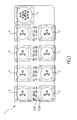
- the invention relates to a splitter 1 for making electrical connections between one or more proximity sensor sensors, in particular of the inductive type, and a machine such as for example a press, in particular via a connection cable.
- the splitter has a plurality of "sensor” bases 2, as well as in particular a “machine” base 3. It should be noted that the latter base “machine” may not exist and then the housing is connected directly, for example by a wired connection.
- said signaling element 4 is a light source or a sound source.
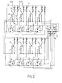
- said means for detecting a leakage current and said switching means may be constituted by an amplifier element controlled by said leakage current i f .
- said amplifier element is a transistor whose base is attacked by said leakage current.
- said amplifier element is powered by the machine.
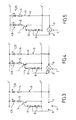
- the transistor 5 is biased by means of two voltage lines V + , V - each associated with a terminal 6, 7 of the machine 3.
- Each sensor base 2 may have at least two terminals 8, 9, one of its terminals 8 being connected to the line V + via one or more diodes 10, the other 9 of its terminals being connected to a terminal 11 of the machine 3.
- the transistor 5 is of the PNP type.
- One 8 of the terminals of the sensor base 2 is connected firstly to the base of the transistor 5 via a resistor 12, and secondly to the said voltage line V + via the diode or diodes 10.
- the other 9 of the terminals of the sensor base 2 is connected, on the one hand, to the line V - via a bypass line 13 comprising at least one resistor 14, and on the other hand, to one 11 of the terminals of the machine 3.
- the emitter of said transistor is connected to said voltage line V + , the collector of said transistor 5 being connected to the voltage line V via a resistor 15 and a light-emitting diode 16.
- the light-emitting diode 16 constitutes said signaling element 4.
- said signaling element 4 is said first signaling element, said distributor 1 further having, for each sensor base 2, means for monitoring the state of the proximity sensor sensor connected to this base.
- the means for monitoring the state of the proximity sensor sensor consist substantially of a second signal element 20 which indicates whether said proximity sensor sensor detects an object or remains at rest in the opposite case.
- said second signaling element 20 is a light source or a sound source.
- the second signaling element 20 is constituted by the light-emitting diode 17 on said branch line 13.
Landscapes
- Physics & Mathematics (AREA)
- General Physics & Mathematics (AREA)
- Electronic Switches (AREA)
- Switches That Are Operated By Magnetic Or Electric Fields (AREA)
Applications Claiming Priority (1)
| Application Number | Priority Date | Filing Date | Title |
|---|---|---|---|
| FR0703688A FR2916536B1 (fr) | 2007-05-24 | 2007-05-24 | Repartiteur pour des capteurs detecteurs de proximite. |
Publications (1)
| Publication Number | Publication Date |
|---|---|
| EP1995601A1 true EP1995601A1 (de) | 2008-11-26 |
Family
ID=38832967
Family Applications (1)
| Application Number | Title | Priority Date | Filing Date |
|---|---|---|---|
| EP08370011A Withdrawn EP1995601A1 (de) | 2007-05-24 | 2008-05-21 | Verteiler für Näherungssensoren |
Country Status (2)
| Country | Link |
|---|---|
| EP (1) | EP1995601A1 (de) |
| FR (1) | FR2916536B1 (de) |
Citations (4)
| Publication number | Priority date | Publication date | Assignee | Title |
|---|---|---|---|---|
| FR2439634A1 (fr) * | 1978-10-24 | 1980-05-23 | Renault | Dispositif de securite controlant l'amenee de la matiere sur une machine a faconner |
| GB2170068A (en) * | 1985-01-11 | 1986-07-23 | Hollingsworth | Line break detector |
| EP1302256A2 (de) * | 2001-10-13 | 2003-04-16 | Bosch Rexroth AG | Einrichtung zur Steuerung eines hydraulischen Zylinders |
| DE19816942B4 (de) * | 1998-04-17 | 2004-02-19 | Schneider Automation Gmbh | Schaltungsanordnung zur Überwachung eines Stromkreises auf Leitungsbruch |
-
2007
- 2007-05-24 FR FR0703688A patent/FR2916536B1/fr not_active Expired - Fee Related
-
2008
- 2008-05-21 EP EP08370011A patent/EP1995601A1/de not_active Withdrawn
Patent Citations (4)
| Publication number | Priority date | Publication date | Assignee | Title |
|---|---|---|---|---|
| FR2439634A1 (fr) * | 1978-10-24 | 1980-05-23 | Renault | Dispositif de securite controlant l'amenee de la matiere sur une machine a faconner |
| GB2170068A (en) * | 1985-01-11 | 1986-07-23 | Hollingsworth | Line break detector |
| DE19816942B4 (de) * | 1998-04-17 | 2004-02-19 | Schneider Automation Gmbh | Schaltungsanordnung zur Überwachung eines Stromkreises auf Leitungsbruch |
| EP1302256A2 (de) * | 2001-10-13 | 2003-04-16 | Bosch Rexroth AG | Einrichtung zur Steuerung eines hydraulischen Zylinders |
Also Published As
| Publication number | Publication date |
|---|---|
| FR2916536A1 (fr) | 2008-11-28 |
| FR2916536B1 (fr) | 2009-08-14 |
Similar Documents
| Publication | Publication Date | Title |
|---|---|---|
| EP0905776B1 (de) | Halbleiteranordnung mit zwei mit einem Erdungsanschluss verbundenen Erdungsverbindungspunkten und Testverfahren dafür | |
| EP1619924B1 (de) | Telefon-Verteilsystem | |
| EP1995601A1 (de) | Verteiler für Näherungssensoren | |
| FR3006462A1 (fr) | Procede et dispositif de lecture de l'etat de variables de contact d'un vehicule automobile | |
| EP2806292B1 (de) | Reflektor für eine Reflex-Modus-Sensorvorrichtung | |
| EP3195474B1 (de) | Elektrische schaltung zur steuerung einer elektrischen vorrichtung mit hoher integrität | |
| WO2019002791A1 (fr) | Capteur en courant | |
| CA2568266A1 (fr) | Systeme de surveillance d'un ensemble de cellules electrochimiques et dispositif de realisation | |
| FR3073676B1 (fr) | Systeme de connexion a collier pour borne de batterie comportant un dispositif de controle de son bon emboitement. | |
| FR2610723A1 (fr) | Capteur de conductivite d'un fluide | |
| WO2023242218A1 (fr) | Installation polyvalente de détection et de localisation de fuites de liquide | |
| EP3748850A1 (de) | Erkennung eines elektrischen defekts in einer elektronischen leistungsvorrichtung | |
| EP3398407A1 (de) | Integrierte schaltung zur isolierungsdefektdetektion und mit einem leitenden anker | |
| EP1771741B1 (de) | Vorrichtung und verfahren zum testen von mindestens einer leitenden verbindung zur bildung einer elektrischen verbindung zwischen einem elektrischen bauteil und einer leiterplatte | |
| CN117832111B (zh) | 一种芯片失效分析测试修复方法 | |
| FR3125131A1 (fr) | Module de détection de coupure de tension d’une batterie de véhicule automobile | |
| EP3654045B1 (de) | Detektions- und übertragungsverfahren von information über einen schlafenden fehler | |
| FR2590410A1 (fr) | Dispositif pour reduire a un minimum les capacites parasites de jonction d'un transistor pnp vertical a collecteur isole | |
| FR3158584A3 (fr) | Connecteur DEL avec une bande lumineuse à couper arbitrairement | |
| EP4508404A1 (de) | Verfahren zur codierung von kommunikationsleitern eines linearen sensors eines systems | |
| FR3150070A1 (fr) | carte électronique pour ensemble modulaire électrique | |
| FR3148650A1 (fr) | Module pour détecter un niveau de charge de batterie, ensemble comprenant le module et aéronef comprenant l’ensemble | |
| FR2993427A1 (fr) | Module de surveillance de defauts a l'armoire d'eclairage public. | |
| FR2880849A1 (fr) | Installation de capteurs, plus particulierement destines a un systeme de parcage | |
| EP0553001A1 (de) | Verfahren und Vorrichtung zum Funktions- und/oder Anwesenheitstest von parallel-geschalteten Elementen |
Legal Events
| Date | Code | Title | Description |
|---|---|---|---|
| PUAI | Public reference made under article 153(3) epc to a published international application that has entered the european phase |
Free format text: ORIGINAL CODE: 0009012 |
|
| AK | Designated contracting states |
Kind code of ref document: A1 Designated state(s): AT BE BG CH CY CZ DE DK EE ES FI FR GB GR HR HU IE IS IT LI LT LU LV MC MT NL NO PL PT RO SE SI SK TR |
|
| AX | Request for extension of the european patent |
Extension state: AL BA MK RS |
|
| AKX | Designation fees paid | ||
| REG | Reference to a national code |
Ref country code: DE Ref legal event code: 8566 |
|
| STAA | Information on the status of an ep patent application or granted ep patent |
Free format text: STATUS: THE APPLICATION IS DEEMED TO BE WITHDRAWN |
|
| 18D | Application deemed to be withdrawn |
Effective date: 20090527 |