EP1995553A1 - System and method for identifying a feature of a workpiece - Google Patents
System and method for identifying a feature of a workpiece Download PDFInfo
- Publication number
- EP1995553A1 EP1995553A1 EP08251727A EP08251727A EP1995553A1 EP 1995553 A1 EP1995553 A1 EP 1995553A1 EP 08251727 A EP08251727 A EP 08251727A EP 08251727 A EP08251727 A EP 08251727A EP 1995553 A1 EP1995553 A1 EP 1995553A1
- Authority
- EP
- European Patent Office
- Prior art keywords
- workpiece
- region
- angle
- composite tape
- incidence
- Prior art date
- Legal status (The legal status is an assumption and is not a legal conclusion. Google has not performed a legal analysis and makes no representation as to the accuracy of the status listed.)
- Granted
Links
Images









Classifications
-
- G—PHYSICS
- G01—MEASURING; TESTING
- G01B—MEASURING LENGTH, THICKNESS OR SIMILAR LINEAR DIMENSIONS; MEASURING ANGLES; MEASURING AREAS; MEASURING IRREGULARITIES OF SURFACES OR CONTOURS
- G01B11/00—Measuring arrangements characterised by the use of optical techniques
- G01B11/24—Measuring arrangements characterised by the use of optical techniques for measuring contours or curvatures
- G01B11/245—Measuring arrangements characterised by the use of optical techniques for measuring contours or curvatures using a plurality of fixed, simultaneously operating transducers
-
- B—PERFORMING OPERATIONS; TRANSPORTING
- B29—WORKING OF PLASTICS; WORKING OF SUBSTANCES IN A PLASTIC STATE IN GENERAL
- B29C—SHAPING OR JOINING OF PLASTICS; SHAPING OF MATERIAL IN A PLASTIC STATE, NOT OTHERWISE PROVIDED FOR; AFTER-TREATMENT OF THE SHAPED PRODUCTS, e.g. REPAIRING
- B29C70/00—Shaping composites, i.e. plastics material comprising reinforcements, fillers or preformed parts, e.g. inserts
- B29C70/04—Shaping composites, i.e. plastics material comprising reinforcements, fillers or preformed parts, e.g. inserts comprising reinforcements only, e.g. self-reinforcing plastics
- B29C70/28—Shaping operations therefor
- B29C70/30—Shaping by lay-up, i.e. applying fibres, tape or broadsheet on a mould, former or core; Shaping by spray-up, i.e. spraying of fibres on a mould, former or core
- B29C70/32—Shaping by lay-up, i.e. applying fibres, tape or broadsheet on a mould, former or core; Shaping by spray-up, i.e. spraying of fibres on a mould, former or core on a rotating mould, former or core
-
- B—PERFORMING OPERATIONS; TRANSPORTING
- B29—WORKING OF PLASTICS; WORKING OF SUBSTANCES IN A PLASTIC STATE IN GENERAL
- B29C—SHAPING OR JOINING OF PLASTICS; SHAPING OF MATERIAL IN A PLASTIC STATE, NOT OTHERWISE PROVIDED FOR; AFTER-TREATMENT OF THE SHAPED PRODUCTS, e.g. REPAIRING
- B29C70/00—Shaping composites, i.e. plastics material comprising reinforcements, fillers or preformed parts, e.g. inserts
- B29C70/04—Shaping composites, i.e. plastics material comprising reinforcements, fillers or preformed parts, e.g. inserts comprising reinforcements only, e.g. self-reinforcing plastics
- B29C70/28—Shaping operations therefor
- B29C70/30—Shaping by lay-up, i.e. applying fibres, tape or broadsheet on a mould, former or core; Shaping by spray-up, i.e. spraying of fibres on a mould, former or core
- B29C70/38—Automated lay-up, e.g. using robots, laying filaments according to predetermined patterns
- B29C70/386—Automated tape laying [ATL]
- B29C70/388—Tape placement heads, e.g. component parts, details or accessories
-
- G—PHYSICS
- G01—MEASURING; TESTING
- G01B—MEASURING LENGTH, THICKNESS OR SIMILAR LINEAR DIMENSIONS; MEASURING ANGLES; MEASURING AREAS; MEASURING IRREGULARITIES OF SURFACES OR CONTOURS
- G01B11/00—Measuring arrangements characterised by the use of optical techniques
- G01B11/24—Measuring arrangements characterised by the use of optical techniques for measuring contours or curvatures
- G01B11/25—Measuring arrangements characterised by the use of optical techniques for measuring contours or curvatures by projecting a pattern, e.g. one or more lines, moiré fringes on the object
-
- G—PHYSICS
- G01—MEASURING; TESTING
- G01N—INVESTIGATING OR ANALYSING MATERIALS BY DETERMINING THEIR CHEMICAL OR PHYSICAL PROPERTIES
- G01N21/00—Investigating or analysing materials by the use of optical means, i.e. using sub-millimetre waves, infrared, visible or ultraviolet light
- G01N21/84—Systems specially adapted for particular applications
- G01N21/88—Investigating the presence of flaws or contamination
- G01N21/89—Investigating the presence of flaws or contamination in moving material, e.g. running paper or textiles
- G01N21/892—Investigating the presence of flaws or contamination in moving material, e.g. running paper or textiles characterised by the flaw, defect or object feature examined
-
- B—PERFORMING OPERATIONS; TRANSPORTING
- B29—WORKING OF PLASTICS; WORKING OF SUBSTANCES IN A PLASTIC STATE IN GENERAL
- B29L—INDEXING SCHEME ASSOCIATED WITH SUBCLASS B29C, RELATING TO PARTICULAR ARTICLES
- B29L2031/00—Other particular articles
- B29L2031/30—Vehicles, e.g. ships or aircraft, or body parts thereof
- B29L2031/3076—Aircrafts
- B29L2031/3082—Fuselages
-
- G—PHYSICS
- G01—MEASURING; TESTING
- G01N—INVESTIGATING OR ANALYSING MATERIALS BY DETERMINING THEIR CHEMICAL OR PHYSICAL PROPERTIES
- G01N21/00—Investigating or analysing materials by the use of optical means, i.e. using sub-millimetre waves, infrared, visible or ultraviolet light
- G01N21/84—Systems specially adapted for particular applications
- G01N2021/8472—Investigation of composite materials
Definitions
- a manufactured article or workpiece may be inspected for presence of defects or for compliance with a manufacturing specification or a design requirement or the like. For example, an inspection may be performed manually, such as by a human inspector with a microscope. Such manual inspection can be time- and labor-intensive. To that end, manual inspection of the workpiece can become a large part of the manufacturing process. Thus, such manual inspection may not be suitable for high-volume manufacturing processes.
- Machine vision systems may be used to inspect a workpiece in order to increase inspection throughput over manual inspection by humans.
- Machine vision systems may analyze two-dimensional information and three-dimensional information to inspect a workpiece.
- resolution, robustness, and speed of measurement that which may be a strength of two-dimensional machine vision analysis conversely may be a weakness of three- dimensional machine vision analysis, and vice versa.
- two- and three-dimensional machine vision analysis of edge detection of a workpiece will be considered.
- two-dimensional edge detection can produce an excellent average measurement of an edge line - because a large portion of an image frame is used; on the other hand, three-dimensional edge detection may be restricted to no more than the size of an image pixel and, therefore, can only locate one point.
- two-dimensional edge detection can be highly susceptible to image noise and surface artifacts that may resemble an edge; on the other hand, three-dimensional edge detection is not susceptible to image noise or surface artifacts at all.
- two-dimensional edge detection may be slow - the two-dimensional edge detection algorithm must analyze an entire image before finding results; on the other hand, three-dimensional edge detection can be fast - the three-dimensional edge detection algorithm only has to analyze an image near a laser signature.
- a two-dimensional machine vision edge detection algorithm may perform well at determining precise location of an edge.
- the two-dimensional machine vision edge detection algorithm may be fooled by image noise and surface artifacts into finding "edges" that are not there.
- analysis of an entire image by the two-dimensional machine vision edge detection algorithm may be time consuming.
- a three-dimensional machine vision algorithm can quickly detect a point without being susceptible to image noise or surface artifacts.
- the three-dimensional machine vision algorithm can only locate one point that is no more than the size of the image pixel.
- a feature of a workpiece can be identified. Two-dimensional data of at least a region of a workpiece is acquired, and three-dimensional data of a portion of the region of the workpiece is acquired. An estimated location of an attribute of a feature of the workpiece is determined from the three-dimensional data, and the feature is identified by analyzing the two-dimensional data in an area surrounding the estimated location of the attribute.
- the feature can include an edge and the attribute can include a point along a line.
- the feature can include a hole and the attribute can include points along a circle.
- the feature can include a chamfered hole and the attribute can include points along two concentric circles.
- the first light source may be disposed at a first angle of incidence relative to a plane of the region and the second light source may be disposed at a second angle of incidence relative to a plane of the region that is greater than the first angle of incidence.
- the first light source can include first and second lighting assemblies disposed towards ends of the region.
- the second light source can include one or more lasers.
- the sensor can include a camera.
- estimated locations of points along lines that define edges may be input into two-dimensional analysis.
- Candidate lines from the points may be formed at the estimated locations, and a median angle of the candidate lines can be determined.
- An angle of each candidate line can be compared with the median angle of the candidate lines, and a candidate line may be invalidated when its angle exceeds the median angle.
- a location of a line can be refined.
- An estimated location of a point is inputted.
- a first search window centered around the estimated location of the point is generated.
- First and second edges of the first search window are each subdivided into edge points. All of the edge points along the first edge are connected with all of the edge points along the second edge to generate a first set of candidate lines, and which of the first set of candidate lines has a maximized power level is determined.
- the length of the candidate line with maximized power level can be extended, and a second search window centered around the candidate line with maximized power level can be generated.
- First and second edges of the second search window each can be subdivided into edge points. All of the edge points along the first edge of the second search window can be connected with all of the edge points along the second edge of the second search window to generate a second set of candidate lines, and which of the second set of candidate lines has a maximized power level can be determined.
- a head assembly can perform a manufacturing operation on a workpiece.
- the head assembly includes a tool moveable relative to a workpiece and configured to perform a manufacturing operation on a workpiece, and a monitoring unit is operatively coupled to and moveable with the tool relative to the workpiece.
- the monitoring unit includes first and second lighting assemblies disposed towards first and second sides of the monitoring unit, respectively, and the first and second lighting assemblies are configured to illuminate at least a region of the workpiece.
- a laser assembly is configured to illuminate a portion of the region of the workpiece upon which the tool has performed the manufacturing operation.
- a sensor is configured to sense an image of the region and the portion of the region, and a processor is operatively coupled to the sensor.
- the processor includes a first component configured to determine an estimated location of an attribute of a feature of the workpiece from three-dimensional data regarding the portion of the region of the workpiece and a second component configured to identify the feature by analyzing two-dimensional data regarding the region in an area surrounding the estimated location of the attribute.
- the tool may be configured to perform an application of a composite tape onto the workpiece, and the monitoring unit may be configured to illuminate at least a region of the composite tape.
- the tool may include a spindle configured to support a supply of the composite tape, and a feed assembly may be configured to feed the composite tape from the supply to the workpiece, the feed assembly having a rotatable compaction roller configured to apply the composite tape onto the workpiece.
- a system can perform a manufacturing operation on a workpiece.
- the system includes at least one head assembly configured to perform a manufacturing operation on a workpiece.
- the head assembly includes a tool moveable relative to a workpiece and configured to perform a manufacturing operation on a workpiece, and a monitoring unit operatively coupled to and moveable with the tool relative to the workpiece.
- the monitoring unit includes first and second lighting assemblies disposed towards first and second sides of the monitoring unit, respectively, and the first and second lighting assemblies are configured to illuminate at least a region of the workpiece.
- a laser assembly is configured to illuminate a portion of the region of the workpiece upon which the tool has performed the manufacturing operation, and a sensor is configured to sense an image of the region and the portion of the region.
- a processor is operatively coupled to the sensor.
- the processor includes a first component configured to determine an estimated location of an attribute of a feature of the workpiece from three-dimensional data regarding the portion of the region of the workpiece, and a second component configured to identify the feature by analyzing two-dimensional data regarding the region in an area surrounding the estimated location of the attribute.
- a translation platform is coupled to the head assembly. The translation platform is configured to operatively position the head assembly proximate the workpiece and to systematically move the head assembly along a translation path proximate the workpiece.
- the tool may be configured to perform an application of a composite tape onto the workpiece, and the monitoring unit may be configured to illuminate at least a region of the composite tape.
- the tool may include a spindle configured to support a supply of the composite tape, and a feed assembly configured to feed the composite tape from the supply to the workpiece, the feed assembly having a rotatable compaction roller configured to apply the composite tape onto the workpiece.
- a feature of a workpiece can be identified.
- Two-dimensional data of at least a region of a workpiece and three-dimensional data of a portion of the region of the workpiece are acquired, such as by illuminating at least the region with at least a first light source disposed at a first angle of incidence relative to a plane of the region and illuminating the portion with a second light source, such as at least one laser, disposed at a second angle of incidence greater than the first angle of incidence.
- An estimated location of an attribute of a feature of the workpiece is determined from the three-dimensional data, and the feature is identified by analyzing the two-dimensional data in an area surrounding the estimated location of the attribute.
- Attributes of features can include without limitation a point along a line of an edge.
- an exemplary system 10 can identify a feature of a workpiece.
- the system 10 is well suited to detect and measure edges of a gap or overlap between components of a workpiece.
- the system 10 may be employed to detect and measure a gap or overlap between edges of composite tape or tow.
- the system 10 is not limited to use in detecting and measuring a gap or overlap between edges of composite tape or tow.
- the system 10 can be used to detect and measure location and size of a hole in a workpiece or a chamfer in a hole in a workpiece.
- the system 10 can identify, that is detect and measure, an attribute of a feature of a workpiece.
- the feature can include an edge and the attribute can include a point along a line.
- the feature can include a hole and the attribute can include points along a circle.
- the feature can include a chamfered hole and the attribute can include a plurality of points along two concentric circles. While the system 10 is not limited to identification of such attributes of such features, for the sake of brevity these attributes and features listed above will provide the examples for explanation of non-limiting, exemplary embodiments disclosed herein.
- Embodiments of the system 10 can detect other features, as well.
- feature is not meant to be limiting, as a feature could be any aspect, discontinuity, imperfection, defect, or flaw in the workpiece that may require attention by a technician, such as for repair or replacement of the workpiece or a portion of the workpiece.
- a flaw could be a material wrinkle or foreign object debris (“FOD”), such as paper, plastic sheet, resin balls, carbon fiber “fuzzballs”, or other material inimical to the production of composite parts.
- FOD foreign object debris
- embodiments of the system 10 can detect the presence of features associated with the workpiece that would not ordinarily be characterized as a "flaw", such as a ply boundary, topology, shape/contour, or a tape edge gap or overlap, the positioning of which are requirements of the engineered workpiece design specification.
- a "flaw" such as a ply boundary, topology, shape/contour, or a tape edge gap or overlap
- Embodiments of the system 10 could be used to inspect any number of workpieces in a variety of industries where detection of features of the workpiece is required or desired, such as in the aircraft, automotive, or construction industries.
- the term "workpiece” is also not meant to be limiting, as the system 10 could be used to inspect any number of parts or structures of different shapes and sizes, such as machined forgings, castings, or panels. For instance, the inspection could be performed on newly manufactured workpieces or existing workpieces that are being inspected for preventive maintenance purposes.
- the workpiece could be any number of composite, plastic, and/or metallic materials.
- the system 10 includes light sources 12 configured to illuminate at least a region 14 of a workpiece 16 and a light source 18 configured to illuminate a portion 20 of the region 14.
- a sensor 22 is configured to sense an image of the region 14 and the portion 20.
- a data processing system 24 is operatively coupled to the sensor 22.
- the data processing system 24 can include a first component configured to determine an estimated location of an attribute of a feature of the workpiece 16 from three-dimensional data regarding the portion 20 and a second component configured to identify the feature by analyzing two-dimensional data regarding the region 14 in an area surrounding the estimated location of the attribute.
- the sensor 22 looks down with a field-of view 26 upon the workpiece 16, such as without limitation composite material, moving past in a direction indicated by arrows 28.
- the light sources 12 illuminate the region 14 with shallow incidence-angle light laterally from both sides of the workpiece 16.
- a gap 30 between edges of components of the workpiece 16, such as composite tape or tows, reflects off edges 32 and 34 from the light sources 12.
- the light source 18, such as a laser, projects a laser fan beam line across the gap 30.
- Information from the sensor 22 is provided to the data processing system 24 to produce frame information. Information regarding exemplary components of the system 10 is discussed in U.S. Patent Application Ser. No. 11/421,273, filed May 31, 2006 .
- the frame information can be used to detect an aspect, potential discontinuity, potential imperfection, potential defect, or potential flaw in the workpiece 16 that may require attention by a technician, such as for repair or replacement of the workpiece 16 or a portion of the workpiece 16, or features associated with the workpiece 16 that would not ordinarily be characterized as a "flaw".
- a technician such as for repair or replacement of the workpiece 16 or a portion of the workpiece 16, or features associated with the workpiece 16 that would not ordinarily be characterized as a "flaw”.
- any potential flaws in the material can be detected during the fabrication process, such as the layup process.
- the process may be stopped and any potential flaws fixed or other actions taken as desired, thereby helping to prevent any flaws from being included in a final part or product.
- the frame information can be used to identify, that is detect and measure, an attribute of a feature of a workpiece.
- Two-dimensional data of the region 14 and three-dimensional data of the portion 20 are acquired by illuminating the region 14 with the light sources 12 and illuminating the portion 20 with the light source 18, and capturing a frame of information with the sensor 22.
- the frame of information is provided to the data processing system 24.
- An estimated location of an attribute of a feature of the workpiece 16 is determined from the three-dimensional data, and the feature is identified by analyzing the two-dimensional data in an area surrounding the estimated location of the attribute. This exemplary use of the frame information will be explained in detail further below.
- the light sources 12 illuminate the region 14 with shallow incidence-angle light laterally from both sides of the workpiece 16.
- Light from the light sources 12 is cast upon the workpiece 16 at a shallow angle of incidence relative to a plane of the workpiece to accentuate edges of components in the workpiece 16, such as composite tape or tows and to cast a shadow into any gap 30 or from any flaw, such as FOD, that may be present in the workpiece 16.
- the incidence angle is shallow - for example, less than about 30°.
- the pitch or roll angle of the light sources 12 could be varied to change the incidence angle of a respective illumination beam on the workpiece 16.
- a range of incidence angles from approximately 5° to approximately 30° may be employed in order to match desired measurement accuracy of tape laps and gaps to the desired vertical depth of field of the embodiment, and to generate more data indicative of surface debris in order to separate actual tape edges from common ridge-like structures in central regions of the workpiece 16.
- Each light source 12 is generally an arrangement of bulbs for generating a light wash, such as a beam of light or other structured light that is configured to illuminate a specific feature on the workpiece 16.
- a light wash such as a beam of light or other structured light that is configured to illuminate a specific feature on the workpiece 16.
- the central portion of any given joint gap will tend to be darker than the surface, and a brighter glint along the top of the edges is produced.
- the two sides of a given joint may be differentiated because of the horizontal order of light and dark lines.
- Each light source 12 is capable of illuminating the workpiece 18 with structured light having a respective color (such as red, blue, green, white, or the like) or additional specific spectral content.
- the light sources 12 may include an array of light emitting diodes (LEDs), incandescent lamps, fluorescent lamps, or any other light source as desired. Additionally, the light sources 12 may be of a specific shape to enhance particular features present in the workpiece 16. Both of the light sources 12 may emit light of the same color.
- LEDs light emitting diodes
- incandescent lamps fluorescent lamps
- fluorescent lamps or any other light source as desired. Additionally, the light sources 12 may be of a specific shape to enhance particular features present in the workpiece 16. Both of the light sources 12 may emit light of the same color.
- one of the light sources 12 may emit light of one color, such as without limitation blue light, and the other light source 12 may emit light of another color, such as without limitation green light.
- Emitting light of one color from one of the light sources 12 and light of another color from the other light source 12 can help accentuate any gaps 30 in the workpiece 16, such as a gap between composite tape or tows.
- the edge 32 on one side of the gap 30 may be illuminated with one color, such as without limitation blue light, from one of the light sources 12 and the edge 34 on the other side of the gap 30 may be illuminated with another color, such as without limitation green light, from the other light source 12.
- the light source 18 suitably includes a laser generator capable of illuminating the workpiece 16 with a fan beam, thereby projecting a laser fan beam line across the gap 30.
- the fan beam is generally a beam of light that spans outwardly in a plane from its origin location.
- a planar fan beam may be oriented by rotating around its optical axis such that the fan produces a signature line on the workpiece 16 substantially perpendicular to the optical axis of the laser generator, in the plane perpendicular to the workpiece 16 described by the incidence angle of the laser generator, or at any angle in between.
- a laser generator used as the light source 12 could be a laser projector, a laser scanner, or the like capable of illuminating the workpiece 16 with a fan beam.
- the pitch or roll angle of the light source 18 could be varied to change the incidence angle of a respective illumination beam on the workpiece 16.
- the signature line from the light source 18 suitably is a different color from the color (or colors) of the light sources 12.
- the signature line from the light source 18 may be a red line and, as a result, the light sources 12 typically may emit any one or a combination of white light, blue light, green light, or the like.
- the light sources 12 and 18 work together as follows, as explained in the non-limiting context of illumination of gaps between composite tows.
- the light sources 12 are positioned to generate linear light washes that are generally parallel to the direction of movement of the workpiece 16, indicated by the arrows 28, and substantially parallel to the edges of gaps, while the light source 18, such as a laser generator, is positioned to generate a fan beam generally perpendicular to the direction of movement of the workpiece 16.
- the light sources 12 are thus configured to illuminate the respective edges 32 and 34 of the gap 30, while the light source 18 is capable of generating a fan beam configured as a signature line 36 on the workpiece 16, thereby highlighting the gap 30 by the mechanism of a "step" in the laser line 36 as seen by the sensor 22.
- Each of the pair of light sources 12 illuminates a respective edge 32 and 34 on an opposite side of the gap 30, perpendicular to the light source 18. Therefore, as mentioned above, the opposing edges 32 and 34 of the gap 30 may be differentiated when the pair of light sources 12 and the light source 18 utilize colors that can be differentiated from one another.
- the sensor 22 is any suitable camera or other image capturing device capable of capturing data indicative of the workpiece 16 such that the data processing system 24 can process the data and determine whether a flaw is present and/or provide information, such as attributes, indicative of various features of the workpiece 16.
- the sensor 22 typically captures images of the workpiece 16, and the data processing system 24 processes the images.
- the sensor 22 is positioned to capture images generally perpendicular to the workpiece 16, although the sensor 22 could be located at other positions and/or orientations if desired, such as in instances in which the surface of the workpiece 16 is non-planar or where a particular feature desired to be detected is best imaged with a particular orientation of the sensor 22.
- the system 10 may include one or more sensors 22, such as without limitation a respective sensor 22 for each tape laying head when used in such a setting.
- the sensor 22 may be a commercially available camera capable of acquiring monochrome images or color images, not necessarily limited to the visible spectrum of light. While use of a color camera can permit enhanced detection of shadows created by light sources 12 of different colors as (as discussed above), one or more tradeoffs over use of a monochrome camera may be involved, such as any one or more of longer exposure times, increased bandwidth, decreased resolution, and/or increased processing power.
- the sensor 22 may be a television or other type of video camera, an infrared-sensitive camera, a visible light camera with infrared-pass filtration, a fiber optic camera, a coaxial camera, Charge Coupled Device (CCD), or Complementary Metal Oxide Sensor (CMOS).
- CCD Charge Coupled Device
- CMOS Complementary Metal Oxide Sensor
- the sensor 22 may also include filter systems or other features by which one or more specific frequencies of light are recorded.
- the sensor 22 can be positioned proximate the workpiece 16 on a stand or mounted to a frame or similar device. For instance and as will be discussed further below, the sensor 22 could be carried proximate to a tape laying head on a lamination machine and translate along with a gantry.
- the data processing system 24 may include a display device (not shown in FIGURE 1 ) that is configured to display images representing data captured by the sensor 22 in real time such that a real-time video display of the captured data may be shown. Also, in some embodiments, the data processing system 24 may be configured to allow a user to capture one or more still images of the data and, for example, to display the still images on a display device or print the images. However, it should also be understood that the sensor 22 may be adapted to capture images at pre-determined times and then to send the images to the data processing system 24 for display by a graphical interface or for output by an output device, such as a printer.
- each sensor 22 may include an associated data processing system 24, while each data processing system 24 may, in turn, be in communication with a central data system (not shown in FIGURE 1 ).
- a central data system in such a tiered or networked architecture could collect and/or further analyze images captured by respective sensors 22 and/or images or other data provided by respective data processing systems 24.
- the data processing system 24 includes a computer processor, one or more computer processing components, or other computing device or devices that may be adapted to execute one or more applications (that is, computer software programs) and to otherwise operate under control of a standard operating system.
- the data processing system 24 may employ various computer software programs for processing and displaying the images captured by the sensor 22.
- the data processing system 24 and, more particularly, the software programs executed by the data system can employ various algorithms for analyzing and interpreting the images captured by the sensor 22.
- the operating system and the various applications, that is computer software programs are stored in a memory device or are otherwise accessible to the processor or other computing device. Construction and operation of computer processors is well known, and a detailed discussion of construction and operation of computer processors is not required for an understanding of embodiments.
- Embodiments of the system 10 could be used during the assembly or processing of the workpiece 16 (such as without limitation as composite tape is being laid upon a mandrel), as well as before or after assembly for providing information characteristic of the workpiece.
- the system 10 could be utilized during the manufacture of aircraft wing skins or stringers, such as in conjunction with a lamination machine for laying onto a workpiece composite tape (typically 0.5" or wider material) or tow (typically less than 0.5" in width) plies of varying shapes. Differing width material may be applied to a given ply, depending upon engineering requirements.
- a lamination machine is a device for laying this resin-impregnated carbon fiber material onto a mandrel to form a workpiece and can have various configurations.
- the lamination machine could include a gantry and a plurality of tape heads for laying down tape of composite material.
- the gantry is capable of translating so that tape is laid as the mandrel rotates and as the gantry translates longitudinally.
- the system 10 is discussed herein in conjunction with a lamination machine for laying composite tape or tow plies onto a workpiece, the system 10 could be employed to inspect various workpieces during various processes.
- the system 10 can be mounted onto a moving lamination head, a separate moving gantry, or statically on any portion of the machine that has appropriate access to the workpiece 16, and may be enabled, disabled, or dynamically reconfigured according to the requirements of a particular manufacturing process.
- an exemplary system 40 can manufacture composite components in accordance with an embodiment.
- the system 40 includes a plurality of head assemblies 42 coupled to a translation platform 44 and operatively positioned proximate a forming tool (or mandrel) 140.
- the translation platform 44 is configured to systematically move the head assemblies 42 along translation paths (for example, three-dimensional paths) proximate the forming tool 46, and each head assembly 42 is configured to perform placement and consolidation of a fiber-reinforced composite tape material onto the forming tool 46 to produce a laminated composite workpiece 16, as described more fully below.
- Each head assembly 42 is operatively coupled to a monitoring unit 48 configured to perform in-process inspections of the manufacturing processes (in this non-limiting example, composite tape application processes) performed by the head assembly 42. Structural and operational features of the monitoring unit 48 are described more fully below. Information regarding exemplary components of the system 40, including the head assembly 42 and the monitoring unit 48, is discussed in U.S. Patent Application Ser. No. 11/383,681, filed May 16, 2006 .
- a data processing system 24 is operatively coupled to the translation platform 44 and to the head assemblies 42.
- the data processing system 24 is configured to implement a control code that transmits control signals to the translation platform 44 and the head assemblies 42.
- the control signals command the movement and functions of the translation platform 44 and the head assemblies 42, thereby causing automated (or semi-automated) manufacturing of the laminated composite workpiece 16 on the forming tool 46.
- the manufacturing system 40 is a multi-head tape lamination machine (MHTLM).
- MHTLM multi-head tape lamination machine
- the system 40 includes eight head assemblies 42 for the placement of composite tape. However, in other embodiments, any desired number of head assemblies 42 may be employed.
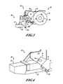
- the head assembly 42 includes a spindle 50 configured to retain a roll 52 of a fiber-reinforced composite tape 54, and a feed assembly 56 configured to receive, guide, feed, and apply the tape 54 from the roll 52 onto the workpiece 16.
- the feed assembly 116 includes a feed roller 58 that receives the tape 54 from the roll 52, and a compaction roller 60 that applies and compresses the tape 54 onto the workpiece 16.
- the feed assembly 56 may include a variety of other components (for example, motors, rollers, guides, sensors, and the like) configured to cooperatively receive, feed, and guide the tape 54 from the roll 52 to the compaction roller 60, as described more fully, for example, in U.S. Patent No.
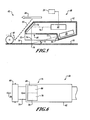
- the monitoring unit 48 includes all of the components of the system 10 ( FIGURE 1 ) except for the data processing system 24. However, in some embodiments the monitoring unit 48 can also include a data processing system 24 that is sized to fit within the monitoring unit 48.
- Two of the light sources 12 are disposed on opposite sides of a bottom portion of a housing 62.
- the housing 62 is coupled to a structural portion 64 of the head assembly 42 proximate to the compaction roller 60, and includes apertures 66 and 68.
- a mirror 70 is positioned within the housing 62 proximate the aperture 68.
- the light source 18 includes two laser fan-beam projectors such as Lasiris Model MFL units commercially-available from Stocker Yale of Salem, New Hampshire, USA, and the sensor 22 is a camera such as a Model KP-M22A video camera, commercially-available from Hitachi Kokusai Electric Incorporated of Tokyo, Japan.
- any suitable laser scanners or cameras may be used.
- the light source 18 provides fan beams 72 that are projected through the aperture 66 onto the composite tape 54 as the signature line 36 after the composite tape 54 has been applied to the workpiece 16 by the compaction roller 60.
- the fan beams 72 intersect the composite tape 54 at an incidence angle ⁇ and produce the signature line 36 that extends laterally (or transversely) across the composite tape 54.
- the incidence angle ⁇ is approximately 15 degrees.
- incidence angles between approximately 10 degrees and approximately 35 degrees may be used. Alternately, any other suitable incidence angle may be used.
- the monitoring unit 48 is configured to detect and characterize various features of interest (for example edges, gaps, wrinkles, puckers, overlaps, foreign object debris (FOD), and the like) along the signature line 36.
- the monitoring unit 48 is positioned such that the signature line 36 is relatively close (that is, as close as practical) to the compaction roller 60 so that features of interest may be detected relatively quickly in the manufacturing process.
- a reflected beam 74 reflects upwardly from the composite tape 54, passes into the housing 62 through the aperture 68, and reflects from the mirror 70 to the sensor 22.
- the reflected beam 74 reflects approximately normally from the composite tape 54.
- any other suitable reflection angle may be used.
- the sensor 22 receives the reflected beam 74 and transmits data to the data processing system 24 for analysis and display.
- a field of view 76 of the sensor 22 through the aperture 68 may be divided into regions of interest (ROI) 78 and 80, and the illuminated signature line 36 is approximately centered within each ROI field of view 76.
- ROI regions of interest
- the data processing system 24 may be configured to analyze the data provided by the sensor 22 to determine whether any features of interest are present, and if so, may characterize such features of interest into various categories including, for example, edges, gaps, wrinkles, overlaps, and various types of FOD.
- the data processing system 24 may be further configured to perform various functions based on the results of the detection and characterization of a feature of interest, including displaying the data from the sensor 22 via a display 82 ( FIGURE 2 ), identifying the feature of interest, notifying an operator, recording information regarding the feature of interest (such as location, type, or the like), and if desired, halting manufacturing operations to permit further inspection and remedial action.
- any of the methods described herein can be implemented using software, firmware (for example, fixed logic circuitry), hardware, manual processing, or any combination of these implementations.
- the terms “module,” “functionality,” and “logic” generally represent software, firmware, hardware, or any combination thereof.
- the module, functionality, or logic represents program code that performs specified tasks when executed on processor(s) (for example, any of microprocessors, controllers, and the like).
- the program code can be stored in one or more computer readable memory devices.
- the methods and systems described herein are platform-independent such that the techniques may be implemented on a variety of commercial computing platforms having a variety of processors.
- computer executable instructions can include routines, programs, objects, components, data structures, procedures, modules, functions, and the like that perform particular functions or implement particular abstract data types.
- the methods may also be practiced in a distributed computing environment where functions are performed by remote processing devices that are linked through a communications network.
- computer executable instructions may be located in both local and remote computer storage media, including memory storage devices.
- one or more of the above-noted operations of the data processing system 24 may be distributed to one or more separate processing units, such as processing units installed within each head assembly 42, or within each monitoring unit 48, or any other suitable arrangement.
- the signature line 36 is used to produce single-pixel addresses of best-guess edge locations in the two-dimensional image, which in some embodiments may then be used to seed a constrained edge-following algorithm that calculates the best fit of the nearest line.
- the relative difference between the light and dark areas may be quite small, and thus edge-finding algorithms discussed further below integrate information from as much of the image as possible in order to produce the best measure of location.
- a starting point in refining attributes of features of a workpiece is to determine best-guess edge locations in the two-dimensional image as highlighted by steps in the three-dimensional laser signature line 36 that crosses the two-dimensional image. These locations are relatively easy to detect by any number of means, and are caused simply by the change in height of the surface of the workpiece 16. It will be appreciated that the direction, or polarity, of the step is determined by the sign of the change in height. Therefore, the nature of a joint (that is, two consecutive edges) is determined to be either a gap or an overlap of material simply by the order of the succession of polarity - that is, minus-to-plus or plus-to-minus.
- the three-dimensional laser signature line 36 across tows 84 of the workpiece 16 includes easily-detected steps 86 and 88 along it due to changes in thickness of the material of the workpiece 16.
- the steps 86 go in one direction on one side of a gap 30 and may be assigned a "negative" polarity.
- the steps 88 go in the other direction on the opposing side of the gap 30 from the steps 86 and may be assigned a "positive" polarity.
- the horizontal ordering of negative and positive polarities of the steps 86 and 88 for the gaps 30 are reversed from the horizontal ordering of the steps 88 and 86 for an overlap 90.
- the three-dimensional laser signature line 36 spans several gaps and overlaps between composite tows.
- a tow 92 slightly overlaps a tow 94, thereby resulting in a "positive" polarity step 88 and a "negative” polarity step 86.
- a small gap exists between the tow 94 and a tow 96, thereby resulting in a "negative” polarity step 86 and a "positive” polarity step 88.
- a medium gap exists between the tow 96 and a tow 98, thereby also resulting in a "negative" polarity step 86 and a "positive” polarity step 88.
- a tow 100 is skewed downwardly toward the right and a tow 102 is skewed downwardly toward the left.
- a large gap exists between the tow 98 and the tow 100, thereby also resulting in a "negative" polarity step 86 and a "positive” polarity step 88.
- the tows 100 and 102 then overlap each other, thereby resulting in a "positive” polarity step 88 and a "negative” polarity step 86.
- a gap exists between the tow 102 and a tow 104, thereby resulting in a "negative” polarity step 86 and a "positive” polarity step 88.
- the tow 104 exactly butts against a tow 106, and no resultant steps 86 or 88 appear in the signature line 36.
- more than one signature line 36 is generated in order to identify a feature such as a circular hole in a workpiece.
- the workpiece 16 can have a flaw or an intentionally-inserted feature in the shape of a circular hole 108.
- attributes of the hole 108 such as the location of the circumference of the hole 108 can be determined with only the one signature line 36.
- more than one signature line is used to identify attributes of the hole 108.
- a light source 18 generates a fan beam 72 that traces a signature line 36 across the hole 108 in the workpiece 16.
- the signature line 36 does not coincide with the diameter of the hole 108 (as would more likely than not be the case).
- the signature line 36 stops at points 110 on the circumference of the hole 108.
- An edge following algorithm such as that discussed further below, can be used to detect a circular edge from the points 110 used as "seeds", as discussed below. However, it may be desirable to provide more points to increase accuracy and robustness.
- another light source 18 generates another fan beam 72A that traces another signature line 36A across the hole 108.
- the signature line 36A stops at points 110A on the circumference of the hole 108.
- Pattern recognition algorithms known by those of ordinary skill in the art can be used to fit the points 110 and 110A to the circumference of the hole, thereby identifying the location of the hole 108. It will be appreciated by those of ordinary skill in the art that the circle can be identified with three points. It will also be appreciated by those of ordinary skill in the art that use of four points (as shown) to identify the circle provides redundancy and, therefore, robustness to the process.
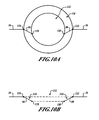
- the chamfered hole has a chamfer 114.
- the signature line 36 need not coincide with the diameter of the hole 112.
- the signature line 36 has a "negative" polarity step 86 between a point 116 on the circumference of the hole 112 and a point 118 at the end of the chamfer 114.
- the signature line 36 has a "positive" polarity step 88 between a point 120 at the end of the chamfer 114 and a point 122 on the circumference of the hole 112.
- the "negative" polarity step 86 between the points 116 and 118 and the "positive” polarity step 88 between the points 120 and 122 can be used to identify the chamfer 114 in the same manner described below for identifying edge locations.
- use of more than one signature line can increase the number of points that can be used as "seeds", thereby providing redundancy and, therefore, robustness to the process.
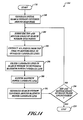
- an exemplary method 130 can be executed to identify a feature of a workpiece.
- the method 130 begins at a block 132.
- two-dimensional data of a region of a workpiece is acquired.
- the region 14 can be illuminated by the light sources 12 and a two-dimensional image acquired by the sensor 22 can be provided to the data processing system 24.
- a block 136 three-dimensional data of a portion of the workpiece is acquired.
- the light source 18 can generate the signature line 36 across the workpiece 16 and three-dimensional information acquired by the sensor 22 can be provided to the data processing system 24.
- No temporal or sequential implication is intended by use of separate process blocks 134 and 136.
- the light sources 12 and 18 illuminate their respective features simultaneously and the sensor 22 senses the image as one frame of information.
- the process blocks 134 and 136 can be considered to occur simultaneously.
- an estimated location of an attribute of a feature of the workpiece is determined from the three-dimensional data. For example, a "best-guess" estimate of an edge location in the two-dimensional image can be obtained by using location of the appropriate step 86 or 88 in the three-dimensional laser signature line 36 that crosses the two-dimensional image.
- the feature is identified by analyzing the two-dimensional data in an area surrounding the estimated location of the attribute.
- a search area can be centered around the estimated location of the attribute - such as location of the step 86 or 88 ( FIGURES 7 and 8 ) as an estimate for location of an edge of a line.
- the two-dimensional data can be analyzed iteratively as described below, increasing the height of the search window and reducing the width of the search window with each iteration.
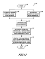
- a method 144 can be executed to refine location of an edge of a line.
- the method 144 starts at a block 146.
- At a block 148 at least a region of a workpiece is illuminated with a pair of light sources that are disposed at a low angle of incidence.
- the region 14 can be illuminated by the light sources 12.
- a portion of the region of the workpiece is illuminated with a light source that is disposed at an angle of incidence relative to a plane of the region that is greater than the low angle of incidence.
- the light source 18 can generate the signature line 36 across the workpiece 16.
- the process blocks 148 and 150 can be considered to occur simultaneously.
- a frame of information is captured.
- an image can be acquired by the sensor 22 and provided to the data processing system 24.
- the frame of information includes two-dimensional information of the image, as illuminated by the light sources 12, and three-dimensional information of the image, as illuminated by the light source 18.
- no temporal or sequential separation from processing at the blocks 148 and 150 is intended by use of a separate process block 152.
- the light sources 12 and 18 illuminate their respective features simultaneously and the sensor 22 contemporaneously acquires the frame of information and provides the frame of information to the data processing system 24.
- the process blocks 148, 150, and 152 can be considered to occur simultaneously.
- an estimated location of a point along a line defining an edge within the workpiece is determined from three-dimensional data from the frame of information.
- the pixel location of a step 86 or 88 ( FIGURES 7 and 8 ) is used as a "best-guess" estimate of an edge of a line, such as an edge of a line of composite tape or tow.
- location of the edge is refined by analyzing two-dimensional data from the frame of information in an area surrounding the estimated location of the point.
- the pixel location of the step 86 or 88 ( FIGURES 7 and 8 ) is used as a "seed" for a search window.
- a search window is centered around the pixel location of the step 86 or 88 ( FIGURES 7 and 8 ).
- the two-dimensional data can be analyzed iteratively as described below, increasing the height of the search window and reducing the width of the search window with each iteration.
- the processing of the block 156 starts at a block 160.
- the estimated locations of points along lines that define edges are input into analysis algorithms of two-dimensional information. For example, for each image frame acquired by the sensor 22, all of the steps 86 and 88 ( FIGURES 7 and 8 ) along the signature line 36 are detected.
- the row and column pixel address and the associated polarity (that is, "positive” or “negative”, as discussed above) of each step are compiled into a list of "seed" or estimated locations.
- the list of seed locations is used as a list of estimated locations or starting points to "cue" a two-dimensional edge finding algorithm (described below).
- candidate lines are formulated along edges from the estimated locations of the points input at the block 162.
- a two-dimensional edge finding algorithm (described below) generates a best-fitting edge line from each of the listed estimated, "seed" locations determined from the steps 86 and 88 ( FIGURES 7 and 8 ) in the signature line 36.
- the best-fitting edge lines are generated according to nearness and polarity of the two-dimensional appearance.
- an angle of each candidate line generated at the block 166 for the frame of information is determined and a median angle is determined from all of the angles of the candidate lines.
- geometric distance between adjacent candidate lines of a pair of candidate lines can be determined at an average image row location of the two associated seed pixels for the candidate lines.
- the image frame is incremented.
- the processing of the block 156 for the image frame stops at a block 176. Processing of the block 156 can be performed again for the next image frame, as desired.
- an exemplary two-dimensional edge finding algorithm formulates searches for an equation of a best edge-like path through a contrast image starting from the estimated location of an edge, that is the "seed" pixel, and continues refinement through a series of iterations. Processing of the block 164 starts at a block 178.
- an initial search window 182 is centered around the location of the seed pixel - that is, the pixel location of the step 86 or 88 along the signature line 36 (that is, the three-dimensional information) that is seen near the edge 32 or 34 (that is the two-dimensional information).
- the initial search window 182 suitably is a rectangle.
- the initial search window 182 has a width sufficient to cover potential misplacement of the seed pixel relative to the real edge, and a height short enough to help ensure that angular variation of the tape or tow relative to the sensor 22 ( FIGURE 1 ) will be contained within the top and bottom edges.
- top and bottom edges 186 and 188 of the search window 182 are subdivided into points 190.
- a block 196 all of the candidate edge filter kernel lines 194 are filtered. Exemplary filtering is discussed in detail further below. Filtering the candidate edge filter kernel lines 194 at the block 196 determines which of the candidate edge filter kernel lines 194 has a maximum power level. Referring additionally to FIGURE 15C , a line 198 is identified as having the maximum filter output power and is retained for further processing in a next iteration.
- the line 198 ( FIGURE 15C ) having the maximum filter output power from the previous iteration is extended vertically by a predetermined distance and is now represented as a line 198A.
- a new search window 182A is generated and is centered around the line 198A.
- the search window 182A suitably can be any quadrilateral as desired. Length of the search window 182A is extended beyond that of the search window 182 ( FIGURES 15A-15C ) and width of the search window 182 is reduced from that of the search window 182 ( FIGURES 15A-15C ).
- top edge 206 and the bottom edge 208 have not been encountered by the top edge 186A and the bottom edge 188A, respectively, then processing of the block 164 returns to the block 184 for a next iteration.
- the top and bottom edges 186A and 188A are subdivided into points 190A.
- the block 192 all of the points 190A along the top edge 186A are connected to all of the points 190A along the bottom edge 188A, thereby generating candidate edge filter kernel lines 194A.
- all of the candidate edge filter kernel lines 194A are filtered.
- a line 198B is identified as having the maximum filter output power and is retained for further processing in a next iteration.
- the line 198B is extended vertically by a predetermined distance.
- a new search window 182A is generated as discussed above and is centered around the line 198B.
- a determination is made whether or not the top edge 206 and the bottom edge 208 of the image frame have been encountered, as discussed above.
- the step 86 or 88 is detected in the laser signature line 36.
- spurious bright lines 212 and 214 that are not associated with changes in surface height of the workpiece (that is, a gap or an overlap) do not appear along the signature line 36 as either a step 86 or a step 88.
- the locations of the spurious lines 212 and 214 are ignored and are not input into processing as estimated pixel seed locations.
- a first iteration searches the initial search window 182 in the image frame, as discussed above.
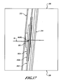
- Additional searching follows in subsequent iterations in the search window 182A, in a subsequent search window 182B, and in a further subsequent search window 182C until the top and bottom edges 206 and 208 of the image frame are encountered.
- the end result is an equation of a line that best fits the edge 32 or 34 that is expected near each seed pixel 86 or 88 along the signature line 36 in the image frame.
- exemplary filtering at the block 196 will now be discussed by way of non-limiting example. As discussed above, filtering the candidate edge filter kernel lines 194, 194A, and so on depending on the iteration being performed, at the block 196 determines which of the candidate edge filter kernel lines has a maximum power level.
- a floating-point geometric coefficient map 216 of an edge detection kernel is generated.
- a central axis a is aligned along the candidate edge filter kernel line and is slanted at the angle of the candidate edge filter kernel line.
- the geometric coefficient map 216 suitably is a matrix comb of rows and columns of +1 multipliers 218 and -1 multipliers 220 oriented along the axis a.
- a filtering operation suitably is executed by determining the sum of all pixel intensities at the center of the +1 multipliers 218 minus the sum of all pixel intensities at the center of the -1 multipliers 220. In the case of the opposite seed polarity, the positions of the +1 multipliers 218 and the -1 multipliers 220 are simply reversed. The candidate line which produces the maximum filter power is then forwarded to the next iteration
- filtering can be speeded up (that is, throttled) by performing a sparse summation.
- the filtering process may be speeded up by leaving out entire rows 222 of the +1 multipliers 218 and the -1 multipliers 220, or by leaving out selected components (that is, selected +1 multipliers 218 and selected -1 multipliers 220) of each row 222.
- this reduction in coefficient number will generally decrease the detection ability of the edge detection algorithm. Therefore, such reduction would work best in cases where the edges in the two-dimensional image frame are clean and well-contrasted.
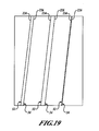
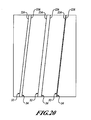
- the end result of the method 144 is an equation of a line 224 or 226 that best fits the edge 32 or 34, respectively, that is expected near each seed pixel 86 or 88 (not shown in FIGURES 19 and 20 along the signature line 36 (not shown in FIGURES 19 and 20 in the image frame.
- the equations for the lines 224 and 226 can be determined even if the image has been degraded, such as by rotation ( FIGURE 19 ) or by noise such as additive or multiplicative noise ( FIGURE 20 ).
Landscapes
- Engineering & Computer Science (AREA)
- Physics & Mathematics (AREA)
- Chemical & Material Sciences (AREA)
- General Physics & Mathematics (AREA)
- Analytical Chemistry (AREA)
- Biochemistry (AREA)
- Mechanical Engineering (AREA)
- Pathology (AREA)
- Health & Medical Sciences (AREA)
- Life Sciences & Earth Sciences (AREA)
- Composite Materials (AREA)
- Immunology (AREA)
- General Health & Medical Sciences (AREA)
- Computer Vision & Pattern Recognition (AREA)
- Textile Engineering (AREA)
- Robotics (AREA)
- Length Measuring Devices By Optical Means (AREA)
- Machine Tool Sensing Apparatuses (AREA)
- Multi-Process Working Machines And Systems (AREA)
- Image Analysis (AREA)
Abstract
Description
- As part of a manufacturing process, a manufactured article or workpiece may be inspected for presence of defects or for compliance with a manufacturing specification or a design requirement or the like. For example, an inspection may be performed manually, such as by a human inspector with a microscope. Such manual inspection can be time- and labor-intensive. To that end, manual inspection of the workpiece can become a large part of the manufacturing process. Thus, such manual inspection may not be suitable for high-volume manufacturing processes.
- Machine vision systems may be used to inspect a workpiece in order to increase inspection throughput over manual inspection by humans. Machine vision systems may analyze two-dimensional information and three-dimensional information to inspect a workpiece. As characterized by resolution, robustness, and speed of measurement, that which may be a strength of two-dimensional machine vision analysis conversely may be a weakness of three- dimensional machine vision analysis, and vice versa.
- For example, two- and three-dimensional machine vision analysis of edge detection of a workpiece, such as a component made of composite tape or tow, will be considered. Regarding resolution, two-dimensional edge detection can produce an excellent average measurement of an edge line - because a large portion of an image frame is used; on the other hand, three-dimensional edge detection may be restricted to no more than the size of an image pixel and, therefore, can only locate one point. Regarding robustness, two-dimensional edge detection can be highly susceptible to image noise and surface artifacts that may resemble an edge; on the other hand, three-dimensional edge detection is not susceptible to image noise or surface artifacts at all. Regarding speed, two-dimensional edge detection may be slow - the two-dimensional edge detection algorithm must analyze an entire image before finding results; on the other hand, three-dimensional edge detection can be fast - the three-dimensional edge detection algorithm only has to analyze an image near a laser signature.
- Therefore, a two-dimensional machine vision edge detection algorithm may perform well at determining precise location of an edge. However, the two-dimensional machine vision edge detection algorithm may be fooled by image noise and surface artifacts into finding "edges" that are not there. Moreover, analysis of an entire image by the two-dimensional machine vision edge detection algorithm may be time consuming. On the other hand, a three-dimensional machine vision algorithm can quickly detect a point without being susceptible to image noise or surface artifacts. However, the three-dimensional machine vision algorithm can only locate one point that is no more than the size of the image pixel.
- Thus, neither two-dimensional machine vision analysis nor three-dimensional machine vision analysis is superior to the other in all three characteristics of resolution, robustness, and speed. However, two-dimensional machine vision analysis and three-dimensional machine vision analysis may be complementary to each other in the characteristics of resolution, robustness, and speed.
- The foregoing examples of related art and limitations associated therewith are intended to be illustrative and not exclusive. Other limitations of the related art will become apparent to those of skill in the art upon a reading of the specification and a study of the drawings.
- The following embodiments and aspects thereof are described and illustrated in conjunction with systems and methods which are meant to be exemplary and illustrative, not limiting in scope. In various embodiments, one or more of the problems described above in the Background have been reduced or eliminated, while other embodiments are directed to other improvements.
- According to exemplary embodiments, a feature of a workpiece can be identified. Two-dimensional data of at least a region of a workpiece is acquired, and three-dimensional data of a portion of the region of the workpiece is acquired. An estimated location of an attribute of a feature of the workpiece is determined from the three-dimensional data, and the feature is identified by analyzing the two-dimensional data in an area surrounding the estimated location of the attribute.
- According to aspects, the feature can include an edge and the attribute can include a point along a line. Alternately, the feature can include a hole and the attribute can include points along a circle. Further, the feature can include a chamfered hole and the attribute can include points along two concentric circles.
- According to other exemplary embodiments, a system for identifying a feature of a workpiece includes a first light source configured to illuminate at least a region of a workpiece and a second light source configured to illuminate a portion of the region of the workpiece. A sensor is configured to sense an image of the region and the portion of the region. A processor is operatively coupled to the sensor. The processor includes a first component configured to determine an estimated location of an attribute of a feature of the workpiece from three-dimensional data regarding the portion of the region of the workpiece and a second component configured to identify the feature by analyzing two-dimensional data regarding the region in an area surrounding the estimated location of the attribute.
- According to aspects, the first light source may be disposed at a first angle of incidence relative to a plane of the region and the second light source may be disposed at a second angle of incidence relative to a plane of the region that is greater than the first angle of incidence. The first light source can include first and second lighting assemblies disposed towards ends of the region. The second light source can include one or more lasers. Further, the sensor can include a camera.
- According to other exemplary embodiments, an edge can be detected. At least a region of a workpiece is illuminated with a pair of first light sources that are disposed at a first angle of incidence relative to a plane of the region and a portion of the region of the workpiece is illuminated with a second light source that is disposed at a second angle of incidence relative to a plane of the region that is greater than the first angle of incidence. A frame of information is captured. An estimated location of a point along a line defining an edge within the workpiece is determined from three-dimensional data from the frame of information, and location of the edge is refined by analyzing two-dimensional data from the frame of information in an area surrounding the estimated location of the point.
- According to aspects, estimated locations of points along lines that define edges may be input into two-dimensional analysis. Candidate lines from the points may be formed at the estimated locations, and a median angle of the candidate lines can be determined. An angle of each candidate line can be compared with the median angle of the candidate lines, and a candidate line may be invalidated when its angle exceeds the median angle.
- According to other exemplary embodiments, a location of a line can be refined. An estimated location of a point is inputted. A first search window centered around the estimated location of the point is generated. First and second edges of the first search window are each subdivided into edge points. All of the edge points along the first edge are connected with all of the edge points along the second edge to generate a first set of candidate lines, and which of the first set of candidate lines has a maximized power level is determined.
- According to aspects, the length of the candidate line with maximized power level can be extended, and a second search window centered around the candidate line with maximized power level can be generated. First and second edges of the second search window each can be subdivided into edge points. All of the edge points along the first edge of the second search window can be connected with all of the edge points along the second edge of the second search window to generate a second set of candidate lines, and which of the second set of candidate lines has a maximized power level can be determined.
- According to other exemplary embodiments, a head assembly can perform a manufacturing operation on a workpiece. The head assembly includes a tool moveable relative to a workpiece and configured to perform a manufacturing operation on a workpiece, and a monitoring unit is operatively coupled to and moveable with the tool relative to the workpiece. The monitoring unit includes first and second lighting assemblies disposed towards first and second sides of the monitoring unit, respectively, and the first and second lighting assemblies are configured to illuminate at least a region of the workpiece. A laser assembly is configured to illuminate a portion of the region of the workpiece upon which the tool has performed the manufacturing operation. A sensor is configured to sense an image of the region and the portion of the region, and a processor is operatively coupled to the sensor. The processor includes a first component configured to determine an estimated location of an attribute of a feature of the workpiece from three-dimensional data regarding the portion of the region of the workpiece and a second component configured to identify the feature by analyzing two-dimensional data regarding the region in an area surrounding the estimated location of the attribute.
- According to aspects, the tool may be configured to perform an application of a composite tape onto the workpiece, and the monitoring unit may be configured to illuminate at least a region of the composite tape. The tool may include a spindle configured to support a supply of the composite tape, and a feed assembly may be configured to feed the composite tape from the supply to the workpiece, the feed assembly having a rotatable compaction roller configured to apply the composite tape onto the workpiece.
- According to other exemplary embodiments, a system can perform a manufacturing operation on a workpiece. The system includes at least one head assembly configured to perform a manufacturing operation on a workpiece. The head assembly includes a tool moveable relative to a workpiece and configured to perform a manufacturing operation on a workpiece, and a monitoring unit operatively coupled to and moveable with the tool relative to the workpiece. The monitoring unit includes first and second lighting assemblies disposed towards first and second sides of the monitoring unit, respectively, and the first and second lighting assemblies are configured to illuminate at least a region of the workpiece. A laser assembly is configured to illuminate a portion of the region of the workpiece upon which the tool has performed the manufacturing operation, and a sensor is configured to sense an image of the region and the portion of the region. A processor is operatively coupled to the sensor. The processor includes a first component configured to determine an estimated location of an attribute of a feature of the workpiece from three-dimensional data regarding the portion of the region of the workpiece, and a second component configured to identify the feature by analyzing two-dimensional data regarding the region in an area surrounding the estimated location of the attribute. A translation platform is coupled to the head assembly. The translation platform is configured to operatively position the head assembly proximate the workpiece and to systematically move the head assembly along a translation path proximate the workpiece.
- According to aspects, the tool may be configured to perform an application of a composite tape onto the workpiece, and the monitoring unit may be configured to illuminate at least a region of the composite tape. The tool may include a spindle configured to support a supply of the composite tape, and a feed assembly configured to feed the composite tape from the supply to the workpiece, the feed assembly having a rotatable compaction roller configured to apply the composite tape onto the workpiece.
- In addition to the exemplary embodiments and aspects described above, further embodiments and aspects will become apparent by reference to the drawings and by study of the following detailed description.
- Exemplary embodiments are illustrated in referenced figures of the drawings. It is intended that the embodiments and figures disclosed herein are to be considered illustrative rather than restrictive.
-
FIGURE 1 is a perspective view of an exemplary system for identifying a feature of a workpiece according to an embodiment; -
FIGURE 2 is an isometric view of an exemplary system for manufacturing composite components according to another embodiment; -
FIGURE 3 is an enlarged side view of an exemplary head assembly of the system ofFIGURE 2 according to another embodiment; -
FIGURE 4 is an enlarged isometric view of an exemplary monitoring unit of the head assembly ofFIGURE 3 ; -
FIGURE 5 is a side cross-sectional view of the monitoring unit ofFIGURE 4 ; -
FIGURE 6 is a top view of the monitoring unit ofFIGURE 4 ; -
FIGURE 7 illustrates steps in an exemplary laser line; -
FIGURE 8 illustrates an exemplary laser signature line illuminating composite tows; -
FIGURE 9A illustrates exemplary illumination of an image frame by more than one laser; -
FIGURE 9B illustrates a feature identified inFIGURE 9A ; -
FIGURE 10A is a top view of an exemplary laser signature line illuminating a chamfered hole; -
FIGURE 10B is a side view of the laser signature line ofFIGURE 10A illuminating the chamfered hole ofFIGURE 10A ; -
FIGURE 11 is a flow chart of an exemplary method of identifying a feature of a workpiece according to an embodiment; -
FIGURE 12 is a flow chart of an exemplary method of refining location of an edge according to an embodiment; -
FIGURE 13 is a flow chart of details of a portion of the flow chart ofFIGURE 12 ; -
FIGURE 14 is a flow chart of details of a portion of the flow chart ofFIGURE 13 ; -
FIGURES 15A-15C illustrate stages of a first iteration of search window processing by an exemplary edge finding algorithm; -
FIGURES 16A-16C illustrate stages of a second iteration of search window processing by an exemplary edge finding algorithm; -
FIGURE 17 superimposes stages of several iterations of search window processing by an exemplary edge finding algorithm; -
FIGURES 18A and 18B illustrate exemplary filtering of candidate lines; and -
FIGURES 19 and20 illustrate edges detected by exemplary embodiments. - Given by way of overview, a feature of a workpiece can be identified. Two-dimensional data of at least a region of a workpiece and three-dimensional data of a portion of the region of the workpiece are acquired, such as by illuminating at least the region with at least a first light source disposed at a first angle of incidence relative to a plane of the region and illuminating the portion with a second light source, such as at least one laser, disposed at a second angle of incidence greater than the first angle of incidence. An estimated location of an attribute of a feature of the workpiece is determined from the three-dimensional data, and the feature is identified by analyzing the two-dimensional data in an area surrounding the estimated location of the attribute. Attributes of features can include without limitation a point along a line of an edge.
- Details of several non-limiting, exemplary embodiments will be set forth below. First, an overview of exemplary embodiments and system components will be set forth. Next, an exemplary embodiment for monitoring automated composite fabrication processes will be explained. Then, exemplary embodiments for identifying features in a workpiece will be explained.
- Referring to
FIGURE 1 , anexemplary system 10 can identify a feature of a workpiece. Given by way of non-limiting example, thesystem 10 is well suited to detect and measure edges of a gap or overlap between components of a workpiece. Given by way of non-limiting example, thesystem 10 may be employed to detect and measure a gap or overlap between edges of composite tape or tow. However, thesystem 10 is not limited to use in detecting and measuring a gap or overlap between edges of composite tape or tow. Given by way of further non-limiting examples, as will be discussed below, thesystem 10 can be used to detect and measure location and size of a hole in a workpiece or a chamfer in a hole in a workpiece. - Thus, in some embodiments the
system 10 can identify, that is detect and measure, an attribute of a feature of a workpiece. To that end, the feature can include an edge and the attribute can include a point along a line. Also, the feature can include a hole and the attribute can include points along a circle. Further, the feature can include a chamfered hole and the attribute can include a plurality of points along two concentric circles. While thesystem 10 is not limited to identification of such attributes of such features, for the sake of brevity these attributes and features listed above will provide the examples for explanation of non-limiting, exemplary embodiments disclosed herein. - Embodiments of the
system 10 can detect other features, as well. It will be understood that the term "feature," as used herein, is not meant to be limiting, as a feature could be any aspect, discontinuity, imperfection, defect, or flaw in the workpiece that may require attention by a technician, such as for repair or replacement of the workpiece or a portion of the workpiece. For example, a flaw could be a material wrinkle or foreign object debris ("FOD"), such as paper, plastic sheet, resin balls, carbon fiber "fuzzballs", or other material inimical to the production of composite parts. Moreover, embodiments of thesystem 10 can detect the presence of features associated with the workpiece that would not ordinarily be characterized as a "flaw", such as a ply boundary, topology, shape/contour, or a tape edge gap or overlap, the positioning of which are requirements of the engineered workpiece design specification. - Embodiments of the
system 10 could be used to inspect any number of workpieces in a variety of industries where detection of features of the workpiece is required or desired, such as in the aircraft, automotive, or construction industries. Thus, the term "workpiece" is also not meant to be limiting, as thesystem 10 could be used to inspect any number of parts or structures of different shapes and sizes, such as machined forgings, castings, or panels. For instance, the inspection could be performed on newly manufactured workpieces or existing workpieces that are being inspected for preventive maintenance purposes. Further, the workpiece could be any number of composite, plastic, and/or metallic materials. - Still by way of overview and still referring to
FIGURE 1 , in an exemplary embodiment thesystem 10 includeslight sources 12 configured to illuminate at least aregion 14 of aworkpiece 16 and alight source 18 configured to illuminate a portion 20 of theregion 14. Asensor 22 is configured to sense an image of theregion 14 and the portion 20. Adata processing system 24 is operatively coupled to thesensor 22. In some embodiments, thedata processing system 24 can include a first component configured to determine an estimated location of an attribute of a feature of the workpiece 16 from three-dimensional data regarding the portion 20 and a second component configured to identify the feature by analyzing two-dimensional data regarding theregion 14 in an area surrounding the estimated location of the attribute. - Still by way of overview, in an embodiment the
sensor 22 looks down with a field-ofview 26 upon theworkpiece 16, such as without limitation composite material, moving past in a direction indicated byarrows 28. Thelight sources 12 illuminate theregion 14 with shallow incidence-angle light laterally from both sides of theworkpiece 16. Agap 30 between edges of components of theworkpiece 16, such as composite tape or tows, reflects off edges 32 and 34 from thelight sources 12. Thelight source 18, such as a laser, projects a laser fan beam line across thegap 30. Information from thesensor 22 is provided to thedata processing system 24 to produce frame information. Information regarding exemplary components of thesystem 10 is discussed inU.S. Patent Application Ser. No. 11/421,273, filed May 31, 2006 - In some embodiments, as discussed above the frame information can be used to detect an aspect, potential discontinuity, potential imperfection, potential defect, or potential flaw in the
workpiece 16 that may require attention by a technician, such as for repair or replacement of theworkpiece 16 or a portion of theworkpiece 16, or features associated with theworkpiece 16 that would not ordinarily be characterized as a "flaw". Such use of the frame information is set forth inU.S. Patent Application Serial No. 11/421,273, filed May 31, 2006 - In other embodiments, the frame information can be used to identify, that is detect and measure, an attribute of a feature of a workpiece. Two-dimensional data of the
region 14 and three-dimensional data of the portion 20 are acquired by illuminating theregion 14 with thelight sources 12 and illuminating the portion 20 with thelight source 18, and capturing a frame of information with thesensor 22. The frame of information is provided to thedata processing system 24. An estimated location of an attribute of a feature of theworkpiece 16 is determined from the three-dimensional data, and the feature is identified by analyzing the two-dimensional data in an area surrounding the estimated location of the attribute. This exemplary use of the frame information will be explained in detail further below. - Details will now be set forth regarding exemplary components of the
system 10. - The
light sources 12 illuminate theregion 14 with shallow incidence-angle light laterally from both sides of theworkpiece 16. Light from thelight sources 12 is cast upon theworkpiece 16 at a shallow angle of incidence relative to a plane of the workpiece to accentuate edges of components in theworkpiece 16, such as composite tape or tows and to cast a shadow into anygap 30 or from any flaw, such as FOD, that may be present in theworkpiece 16. According to embodiments, the incidence angle is shallow - for example, less than about 30°. The pitch or roll angle of thelight sources 12 could be varied to change the incidence angle of a respective illumination beam on theworkpiece 16. Thus, a range of incidence angles from approximately 5° to approximately 30° may be employed in order to match desired measurement accuracy of tape laps and gaps to the desired vertical depth of field of the embodiment, and to generate more data indicative of surface debris in order to separate actual tape edges from common ridge-like structures in central regions of theworkpiece 16. - Each
light source 12 is generally an arrangement of bulbs for generating a light wash, such as a beam of light or other structured light that is configured to illuminate a specific feature on theworkpiece 16. Within the non-limiting context of a gap between composite tape or tows, the central portion of any given joint gap will tend to be darker than the surface, and a brighter glint along the top of the edges is produced. Thus, the two sides of a given joint may be differentiated because of the horizontal order of light and dark lines. Eachlight source 12 is capable of illuminating the workpiece 18 with structured light having a respective color (such as red, blue, green, white, or the like) or additional specific spectral content. Thelight sources 12 may include an array of light emitting diodes (LEDs), incandescent lamps, fluorescent lamps, or any other light source as desired. Additionally, thelight sources 12 may be of a specific shape to enhance particular features present in theworkpiece 16. Both of thelight sources 12 may emit light of the same color. - Alternately, one of the
light sources 12 may emit light of one color, such as without limitation blue light, and the otherlight source 12 may emit light of another color, such as without limitation green light. Emitting light of one color from one of thelight sources 12 and light of another color from the otherlight source 12 can help accentuate anygaps 30 in theworkpiece 16, such as a gap between composite tape or tows. For example, theedge 32 on one side of thegap 30 may be illuminated with one color, such as without limitation blue light, from one of thelight sources 12 and theedge 34 on the other side of thegap 30 may be illuminated with another color, such as without limitation green light, from the otherlight source 12. - The
light source 18 suitably includes a laser generator capable of illuminating the workpiece 16 with a fan beam, thereby projecting a laser fan beam line across thegap 30. The fan beam is generally a beam of light that spans outwardly in a plane from its origin location. A planar fan beam may be oriented by rotating around its optical axis such that the fan produces a signature line on theworkpiece 16 substantially perpendicular to the optical axis of the laser generator, in the plane perpendicular to theworkpiece 16 described by the incidence angle of the laser generator, or at any angle in between. Thus, a laser generator used as thelight source 12 could be a laser projector, a laser scanner, or the like capable of illuminating the workpiece 16 with a fan beam. The pitch or roll angle of thelight source 18 could be varied to change the incidence angle of a respective illumination beam on theworkpiece 16. The signature line from thelight source 18 suitably is a different color from the color (or colors) of thelight sources 12. Typically, the signature line from thelight source 18 may be a red line and, as a result, thelight sources 12 typically may emit any one or a combination of white light, blue light, green light, or the like. - The
light sources light sources 12 are positioned to generate linear light washes that are generally parallel to the direction of movement of theworkpiece 16, indicated by thearrows 28, and substantially parallel to the edges of gaps, while thelight source 18, such as a laser generator, is positioned to generate a fan beam generally perpendicular to the direction of movement of theworkpiece 16. Thelight sources 12 are thus configured to illuminate therespective edges gap 30, while thelight source 18 is capable of generating a fan beam configured as asignature line 36 on theworkpiece 16, thereby highlighting thegap 30 by the mechanism of a "step" in thelaser line 36 as seen by thesensor 22. Each of the pair oflight sources 12 illuminates arespective edge gap 30, perpendicular to thelight source 18. Therefore, as mentioned above, the opposingedges gap 30 may be differentiated when the pair oflight sources 12 and thelight source 18 utilize colors that can be differentiated from one another. - The
sensor 22 is any suitable camera or other image capturing device capable of capturing data indicative of theworkpiece 16 such that thedata processing system 24 can process the data and determine whether a flaw is present and/or provide information, such as attributes, indicative of various features of theworkpiece 16. In particular, thesensor 22 typically captures images of theworkpiece 16, and thedata processing system 24 processes the images. Thesensor 22 is positioned to capture images generally perpendicular to theworkpiece 16, although thesensor 22 could be located at other positions and/or orientations if desired, such as in instances in which the surface of theworkpiece 16 is non-planar or where a particular feature desired to be detected is best imaged with a particular orientation of thesensor 22. Thesystem 10 may include one ormore sensors 22, such as without limitation arespective sensor 22 for each tape laying head when used in such a setting. - The
sensor 22 may be a commercially available camera capable of acquiring monochrome images or color images, not necessarily limited to the visible spectrum of light. While use of a color camera can permit enhanced detection of shadows created bylight sources 12 of different colors as (as discussed above), one or more tradeoffs over use of a monochrome camera may be involved, such as any one or more of longer exposure times, increased bandwidth, decreased resolution, and/or increased processing power. Given by way of non-limiting example, in one embodiment, thesensor 22 may be a television or other type of video camera, an infrared-sensitive camera, a visible light camera with infrared-pass filtration, a fiber optic camera, a coaxial camera, Charge Coupled Device (CCD), or Complementary Metal Oxide Sensor (CMOS). Thesensor 22 may also include filter systems or other features by which one or more specific frequencies of light are recorded. Thesensor 22 can be positioned proximate theworkpiece 16 on a stand or mounted to a frame or similar device. For instance and as will be discussed further below, thesensor 22 could be carried proximate to a tape laying head on a lamination machine and translate along with a gantry. - In some embodiments, the
data processing system 24 may include a display device (not shown inFIGURE 1 ) that is configured to display images representing data captured by thesensor 22 in real time such that a real-time video display of the captured data may be shown. Also, in some embodiments, thedata processing system 24 may be configured to allow a user to capture one or more still images of the data and, for example, to display the still images on a display device or print the images. However, it should also be understood that thesensor 22 may be adapted to capture images at pre-determined times and then to send the images to thedata processing system 24 for display by a graphical interface or for output by an output device, such as a printer. - It will be further understood that each
sensor 22 may include an associateddata processing system 24, while eachdata processing system 24 may, in turn, be in communication with a central data system (not shown inFIGURE 1 ). Thus, a central data system in such a tiered or networked architecture could collect and/or further analyze images captured byrespective sensors 22 and/or images or other data provided by respectivedata processing systems 24. - In addition, the
data processing system 24 includes a computer processor, one or more computer processing components, or other computing device or devices that may be adapted to execute one or more applications (that is, computer software programs) and to otherwise operate under control of a standard operating system. For instance, thedata processing system 24 may employ various computer software programs for processing and displaying the images captured by thesensor 22. As will be explained in further detail below, thedata processing system 24 and, more particularly, the software programs executed by the data system can employ various algorithms for analyzing and interpreting the images captured by thesensor 22. Typically, the operating system and the various applications, that is computer software programs, are stored in a memory device or are otherwise accessible to the processor or other computing device. Construction and operation of computer processors is well known, and a detailed discussion of construction and operation of computer processors is not required for an understanding of embodiments. - Now that an overview of the
system 10 and its components has been set forth, an exemplary application will be explained by way of non-limiting example. - Embodiments of the
system 10 could be used during the assembly or processing of the workpiece 16 (such as without limitation as composite tape is being laid upon a mandrel), as well as before or after assembly for providing information characteristic of the workpiece. For example, thesystem 10 could be utilized during the manufacture of aircraft wing skins or stringers, such as in conjunction with a lamination machine for laying onto a workpiece composite tape (typically 0.5" or wider material) or tow (typically less than 0.5" in width) plies of varying shapes. Differing width material may be applied to a given ply, depending upon engineering requirements. A lamination machine, as known to those skilled in the art, is a device for laying this resin-impregnated carbon fiber material onto a mandrel to form a workpiece and can have various configurations. For instance, the lamination machine could include a gantry and a plurality of tape heads for laying down tape of composite material. The gantry is capable of translating so that tape is laid as the mandrel rotates and as the gantry translates longitudinally. However, although thesystem 10 is discussed herein in conjunction with a lamination machine for laying composite tape or tow plies onto a workpiece, thesystem 10 could be employed to inspect various workpieces during various processes. For example, thesystem 10 can be mounted onto a moving lamination head, a separate moving gantry, or statically on any portion of the machine that has appropriate access to theworkpiece 16, and may be enabled, disabled, or dynamically reconfigured according to the requirements of a particular manufacturing process. - To that end and referring now to
FIGURE 2 , an exemplary system 40 can manufacture composite components in accordance with an embodiment. In this embodiment, the system 40 includes a plurality ofhead assemblies 42 coupled to atranslation platform 44 and operatively positioned proximate a forming tool (or mandrel) 140. Thetranslation platform 44 is configured to systematically move thehead assemblies 42 along translation paths (for example, three-dimensional paths) proximate the formingtool 46, and eachhead assembly 42 is configured to perform placement and consolidation of a fiber-reinforced composite tape material onto the formingtool 46 to produce a laminatedcomposite workpiece 16, as described more fully below. Eachhead assembly 42 is operatively coupled to amonitoring unit 48 configured to perform in-process inspections of the manufacturing processes (in this non-limiting example, composite tape application processes) performed by thehead assembly 42. Structural and operational features of themonitoring unit 48 are described more fully below. Information regarding exemplary components of the system 40, including thehead assembly 42 and themonitoring unit 48, is discussed inU.S. Patent Application Ser. No. 11/383,681, filed May 16, 2006 - A
data processing system 24 is operatively coupled to thetranslation platform 44 and to thehead assemblies 42. In addition to the functions described above and that will be described further below, thedata processing system 24 is configured to implement a control code that transmits control signals to thetranslation platform 44 and thehead assemblies 42. The control signals command the movement and functions of thetranslation platform 44 and thehead assemblies 42, thereby causing automated (or semi-automated) manufacturing of the laminatedcomposite workpiece 16 on the formingtool 46. In the exemplary embodiment shown, the manufacturing system 40 is a multi-head tape lamination machine (MHTLM). In one particular embodiment, the system 40 includes eighthead assemblies 42 for the placement of composite tape. However, in other embodiments, any desired number ofhead assemblies 42 may be employed. - Referring now to
FIGURE 3 , thehead assembly 42 includes aspindle 50 configured to retain aroll 52 of a fiber-reinforcedcomposite tape 54, and afeed assembly 56 configured to receive, guide, feed, and apply thetape 54 from theroll 52 onto theworkpiece 16. More specifically, thefeed assembly 116 includes afeed roller 58 that receives thetape 54 from theroll 52, and acompaction roller 60 that applies and compresses thetape 54 onto theworkpiece 16. Thefeed assembly 56 may include a variety of other components (for example, motors, rollers, guides, sensors, and the like) configured to cooperatively receive, feed, and guide thetape 54 from theroll 52 to thecompaction roller 60, as described more fully, for example, inU.S. Patent No. 6,799,619 B2 issued to Holmes et al. , andU.S. Patent No. 6,871,684 B2 issued to Engelbart et al. , as well as in co-pending, commonly-ownedU.S. Patent Application Nos. 09/998,478 and10/644,148 - Referring now to
FIGURES 4-5 , themonitoring unit 48 includes all of the components of the system 10 (FIGURE 1 ) except for thedata processing system 24. However, in some embodiments themonitoring unit 48 can also include adata processing system 24 that is sized to fit within themonitoring unit 48. Two of thelight sources 12 are disposed on opposite sides of a bottom portion of ahousing 62. Thehousing 62 is coupled to astructural portion 64 of thehead assembly 42 proximate to thecompaction roller 60, and includesapertures mirror 70 is positioned within thehousing 62 proximate theaperture 68. In one particular embodiment, thelight source 18 includes two laser fan-beam projectors such as Lasiris Model MFL units commercially-available from Stocker Yale of Salem, New Hampshire, USA, and thesensor 22 is a camera such as a Model KP-M22A video camera, commercially-available from Hitachi Kokusai Electric Incorporated of Tokyo, Japan. In other embodiments, any suitable laser scanners or cameras may be used. - As the
head assembly 42 is traversed over theworkpiece 16 in a direction of travel indicated by thearrow 28, thelight source 18 provides fan beams 72 that are projected through theaperture 66 onto thecomposite tape 54 as thesignature line 36 after thecomposite tape 54 has been applied to theworkpiece 16 by thecompaction roller 60. The fan beams 72 intersect thecomposite tape 54 at an incidence angle α and produce thesignature line 36 that extends laterally (or transversely) across thecomposite tape 54. In one particular embodiment, the incidence angle α is approximately 15 degrees. However, in other embodiments, incidence angles between approximately 10 degrees and approximately 35 degrees may be used. Alternately, any other suitable incidence angle may be used. As described more fully below, themonitoring unit 48 is configured to detect and characterize various features of interest (for example edges, gaps, wrinkles, puckers, overlaps, foreign object debris (FOD), and the like) along thesignature line 36. Preferably, themonitoring unit 48 is positioned such that thesignature line 36 is relatively close (that is, as close as practical) to thecompaction roller 60 so that features of interest may be detected relatively quickly in the manufacturing process. - A reflected
beam 74 reflects upwardly from thecomposite tape 54, passes into thehousing 62 through theaperture 68, and reflects from themirror 70 to thesensor 22. In one particular embodiment, the reflectedbeam 74 reflects approximately normally from thecomposite tape 54. However, in other embodiments, any other suitable reflection angle may be used. Thesensor 22 receives the reflectedbeam 74 and transmits data to thedata processing system 24 for analysis and display. - Referring now to
FIGURE 6 , in one exemplary embodiment a field ofview 76 of thesensor 22 through theaperture 68 may be divided into regions of interest (ROI) 78 and 80, and theilluminated signature line 36 is approximately centered within each ROI field ofview 76. - Now that an exemplary embodiment for monitoring automated composite fabrication processes has been explained, exemplary embodiments for identifying features in a workpiece will be explained.
- Referring now to
FIGURES 1-6 , thedata processing system 24 may be configured to analyze the data provided by thesensor 22 to determine whether any features of interest are present, and if so, may characterize such features of interest into various categories including, for example, edges, gaps, wrinkles, overlaps, and various types of FOD. Thedata processing system 24 may be further configured to perform various functions based on the results of the detection and characterization of a feature of interest, including displaying the data from thesensor 22 via a display 82 (FIGURE 2 ), identifying the feature of interest, notifying an operator, recording information regarding the feature of interest (such as location, type, or the like), and if desired, halting manufacturing operations to permit further inspection and remedial action. - Generally, any of the methods described herein can be implemented using software, firmware (for example, fixed logic circuitry), hardware, manual processing, or any combination of these implementations. The terms "module," "functionality," and "logic" generally represent software, firmware, hardware, or any combination thereof. In the case of a software implementation, the module, functionality, or logic represents program code that performs specified tasks when executed on processor(s) (for example, any of microprocessors, controllers, and the like). The program code can be stored in one or more computer readable memory devices. Further, the methods and systems described herein are platform-independent such that the techniques may be implemented on a variety of commercial computing platforms having a variety of processors.
- Furthermore, one or more of the methods disclosed herein may be described in the general context of computer executable instructions. Generally, computer executable instructions can include routines, programs, objects, components, data structures, procedures, modules, functions, and the like that perform particular functions or implement particular abstract data types. The methods may also be practiced in a distributed computing environment where functions are performed by remote processing devices that are linked through a communications network. In a distributed computing environment, computer executable instructions may be located in both local and remote computer storage media, including memory storage devices. For example, in alternate embodiments, one or more of the above-noted operations of the
data processing system 24 may be distributed to one or more separate processing units, such as processing units installed within eachhead assembly 42, or within each monitoringunit 48, or any other suitable arrangement. - Referring now to
FIGURES 1 and7 , information contained within thesignature line 36 will be discussed. Thesignature line 36 is used to produce single-pixel addresses of best-guess edge locations in the two-dimensional image, which in some embodiments may then be used to seed a constrained edge-following algorithm that calculates the best fit of the nearest line. The relative difference between the light and dark areas may be quite small, and thus edge-finding algorithms discussed further below integrate information from as much of the image as possible in order to produce the best measure of location. - Thus, a starting point in refining attributes of features of a workpiece, such as locations of edges of a gap or overlap, is to determine best-guess edge locations in the two-dimensional image as highlighted by steps in the three-dimensional
laser signature line 36 that crosses the two-dimensional image. These locations are relatively easy to detect by any number of means, and are caused simply by the change in height of the surface of theworkpiece 16. It will be appreciated that the direction, or polarity, of the step is determined by the sign of the change in height. Therefore, the nature of a joint (that is, two consecutive edges) is determined to be either a gap or an overlap of material simply by the order of the succession of polarity - that is, minus-to-plus or plus-to-minus. - With this context in mind and referring to
FIGURE 7 , the three-dimensionallaser signature line 36 acrosstows 84 of theworkpiece 16 includes easily-detectedsteps workpiece 16. Thesteps 86 go in one direction on one side of agap 30 and may be assigned a "negative" polarity. Thesteps 88 go in the other direction on the opposing side of thegap 30 from thesteps 86 and may be assigned a "positive" polarity. It will be noted that the horizontal ordering of negative and positive polarities of thesteps gaps 30 are reversed from the horizontal ordering of thesteps overlap 90. - Referring now to
FIGURE 8 , the three-dimensionallaser signature line 36 spans several gaps and overlaps between composite tows. The following description proceeds from left-to-right as shown inFIGURE 8 . Atow 92 slightly overlaps atow 94, thereby resulting in a "positive"polarity step 88 and a "negative"polarity step 86. A small gap exists between thetow 94 and atow 96, thereby resulting in a "negative"polarity step 86 and a "positive"polarity step 88. A medium gap exists between thetow 96 and atow 98, thereby also resulting in a "negative"polarity step 86 and a "positive"polarity step 88. - Still referring to
FIGURE 8 , atow 100 is skewed downwardly toward the right and atow 102 is skewed downwardly toward the left. A large gap exists between thetow 98 and thetow 100, thereby also resulting in a "negative"polarity step 86 and a "positive"polarity step 88. Thetows polarity step 88 and a "negative"polarity step 86. A gap exists between thetow 102 and atow 104, thereby resulting in a "negative"polarity step 86 and a "positive"polarity step 88. Thetow 104 exactly butts against atow 106, and noresultant steps signature line 36. - Referring now to
FIGURES 9A and9B , in some embodiments more than onesignature line 36 is generated in order to identify a feature such as a circular hole in a workpiece. For example, theworkpiece 16 can have a flaw or an intentionally-inserted feature in the shape of acircular hole 108. When thesignature line 36 coincides with the diameter of thecircular hole 108, attributes of thehole 108 such as the location of the circumference of thehole 108 can be determined with only the onesignature line 36. In the event that thesignature line 36 does not coincide with the diameter of thehole 108, then more than one signature line is used to identify attributes of thehole 108. - For example, a
light source 18 generates afan beam 72 that traces asignature line 36 across thehole 108 in theworkpiece 16. Thesignature line 36 does not coincide with the diameter of the hole 108 (as would more likely than not be the case). Thesignature line 36 stops atpoints 110 on the circumference of thehole 108. An edge following algorithm, such as that discussed further below, can be used to detect a circular edge from thepoints 110 used as "seeds", as discussed below. However, it may be desirable to provide more points to increase accuracy and robustness. To that end, anotherlight source 18 generates another fan beam 72A that traces anothersignature line 36A across thehole 108. Thesignature line 36A stops atpoints 110A on the circumference of thehole 108. Pattern recognition algorithms known by those of ordinary skill in the art can be used to fit thepoints hole 108. It will be appreciated by those of ordinary skill in the art that the circle can be identified with three points. It will also be appreciated by those of ordinary skill in the art that use of four points (as shown) to identify the circle provides redundancy and, therefore, robustness to the process. - Referring now to
FIGURES 10A and 10B , only onesignature line 36 can be used to identify achamfered hole 112. The chamfered hole has achamfer 114. To identify thechamfer 114, thesignature line 36 need not coincide with the diameter of thehole 112. Thesignature line 36 has a "negative"polarity step 86 between apoint 116 on the circumference of thehole 112 and apoint 118 at the end of thechamfer 114. Likewise, thesignature line 36 has a "positive"polarity step 88 between apoint 120 at the end of thechamfer 114 and a point 122 on the circumference of thehole 112. The "negative"polarity step 86 between thepoints polarity step 88 between thepoints 120 and 122 can be used to identify thechamfer 114 in the same manner described below for identifying edge locations. As discussed above, use of more than one signature line can increase the number of points that can be used as "seeds", thereby providing redundancy and, therefore, robustness to the process. - Referring now to
FIGURE 11 andFIGURE 1 , in general anexemplary method 130 can be executed to identify a feature of a workpiece. Themethod 130 begins at ablock 132. At ablock 134, two-dimensional data of a region of a workpiece is acquired. For example, theregion 14 can be illuminated by thelight sources 12 and a two-dimensional image acquired by thesensor 22 can be provided to thedata processing system 24. - At a block 136 three-dimensional data of a portion of the workpiece is acquired. For example, the
light source 18 can generate thesignature line 36 across theworkpiece 16 and three-dimensional information acquired by thesensor 22 can be provided to thedata processing system 24. No temporal or sequential implication is intended by use of separate process blocks 134 and 136. In exemplary embodiments, thelight sources sensor 22 senses the image as one frame of information. Thus, the process blocks 134 and 136 can be considered to occur simultaneously. - At a
block 138 an estimated location of an attribute of a feature of the workpiece is determined from the three-dimensional data. For example, a "best-guess" estimate of an edge location in the two-dimensional image can be obtained by using location of theappropriate step laser signature line 36 that crosses the two-dimensional image. - At a block 140 the feature is identified by analyzing the two-dimensional data in an area surrounding the estimated location of the attribute. For example, a search area can be centered around the estimated location of the attribute - such as location of the
step 86 or 88 (FIGURES 7 and 8 ) as an estimate for location of an edge of a line. If desired, the two-dimensional data can be analyzed iteratively as described below, increasing the height of the search window and reducing the width of the search window with each iteration. When the analysis of the block 140 is completed, themethod 130 stops at ablock 142. - Referring now to
FIGURE 12 andFIGURE 1 , in an exemplary embodiment a method 144 can be executed to refine location of an edge of a line. The method 144 starts at ablock 146. At ablock 148, at least a region of a workpiece is illuminated with a pair of light sources that are disposed at a low angle of incidence. For example, theregion 14 can be illuminated by thelight sources 12. - At a block 150 a portion of the region of the workpiece is illuminated with a light source that is disposed at an angle of incidence relative to a plane of the region that is greater than the low angle of incidence. For example, the
light source 18 can generate thesignature line 36 across theworkpiece 16. Again, it will be understood that no temporal or sequential implication is intended by use of separate process blocks 148 and 150. In exemplary embodiments, thelight sources - At a block 152 a frame of information is captured. For example, an image can be acquired by the
sensor 22 and provided to thedata processing system 24. The frame of information includes two-dimensional information of the image, as illuminated by thelight sources 12, and three-dimensional information of the image, as illuminated by thelight source 18. Once again, no temporal or sequential separation from processing at theblocks light sources sensor 22 contemporaneously acquires the frame of information and provides the frame of information to thedata processing system 24. Thus, the process blocks 148, 150, and 152 can be considered to occur simultaneously. - At a
block 154 an estimated location of a point along a line defining an edge within the workpiece is determined from three-dimensional data from the frame of information. For example, the pixel location of astep 86 or 88 (FIGURES 7 and 8 ) is used as a "best-guess" estimate of an edge of a line, such as an edge of a line of composite tape or tow. - At a
block 156, location of the edge is refined by analyzing two-dimensional data from the frame of information in an area surrounding the estimated location of the point. For example, the pixel location of thestep 86 or 88 (FIGURES 7 and 8 ) is used as a "seed" for a search window. A search window is centered around the pixel location of thestep 86 or 88 (FIGURES 7 and 8 ). The two-dimensional data can be analyzed iteratively as described below, increasing the height of the search window and reducing the width of the search window with each iteration. When the analysis of theblock 156 is completed, the method 144 stops at ablock 158. - Referring now to
FIGURE 13 , details of exemplary processing of the block 156 (FIGURE 12 ) will now be explained. The processing of theblock 156 starts at ablock 160. At aninput block 162, the estimated locations of points along lines that define edges are input into analysis algorithms of two-dimensional information. For example, for each image frame acquired by thesensor 22, all of thesteps 86 and 88 (FIGURES 7 and 8 ) along thesignature line 36 are detected. The row and column pixel address and the associated polarity (that is, "positive" or "negative", as discussed above) of each step are compiled into a list of "seed" or estimated locations. The list of seed locations is used as a list of estimated locations or starting points to "cue" a two-dimensional edge finding algorithm (described below). - At a
block 164, candidate lines are formulated along edges from the estimated locations of the points input at theblock 162. A two-dimensional edge finding algorithm (described below) generates a best-fitting edge line from each of the listed estimated, "seed" locations determined from thesteps 86 and 88 (FIGURES 7 and 8 ) in thesignature line 36. As will be explained below, the best-fitting edge lines are generated according to nearness and polarity of the two-dimensional appearance. - At a
block 166, an angle of each candidate line generated at theblock 166 for the frame of information is determined and a median angle is determined from all of the angles of the candidate lines. At adecision block 168, a determination is made whether a candidate line's angle exceeds the median angle. For example, when theworkpiece 16 is made of composite tape or tows, the candidate lines should all be substantially parallel to each other, within a range of degrees. The range of degrees can depend on the nature of the workpiece under measurement. For example, for composite tape or tow, the range of degrees can be around two degrees. If a candidate line's angle exceeds the median angle, then at ablock 170 the candidate line is invalidated and is removed from further processing and processing of the block proceeds to ablock 172. If a candidate's line does not exceed the median angle, then processing of theblock 156 also proceeds to theblock 172. - At the
block 172 width of a most-probable gap or overlap between components of theworkpiece 16, such as composite tape or tows. For example, geometric distance between adjacent candidate lines of a pair of candidate lines can be determined at an average image row location of the two associated seed pixels for the candidate lines. - After gap or overlap measurements are made, at a
block 174 the image frame is incremented. The processing of theblock 156 for the image frame stops at ablock 176. Processing of theblock 156 can be performed again for the next image frame, as desired. - Referring now to
FIGURE 14 , at theblock 164 an exemplary two-dimensional edge finding algorithm formulates searches for an equation of a best edge-like path through a contrast image starting from the estimated location of an edge, that is the "seed" pixel, and continues refinement through a series of iterations. Processing of theblock 164 starts at ablock 178. - Referring now to
FIGURES 14 and15A , at ablock 180 aninitial search window 182 is centered around the location of the seed pixel - that is, the pixel location of thestep edge 32 or 34 (that is the two-dimensional information). Theinitial search window 182 suitably is a rectangle. Theinitial search window 182 has a width sufficient to cover potential misplacement of the seed pixel relative to the real edge, and a height short enough to help ensure that angular variation of the tape or tow relative to the sensor 22 (FIGURE 1 ) will be contained within the top and bottom edges. - At a
block 184, top andbottom edges 186 and 188 of thesearch window 182 are subdivided intopoints 190. - At a
block 192 all of thepoints 190 along the top edge 186 are connected to all of thepoints 190 along thebottom edge 188. Connecting all of thepoints 190 in this manner generates candidate edge filter kernel lines 194. - At a
block 196 all of the candidate edgefilter kernel lines 194 are filtered. Exemplary filtering is discussed in detail further below. Filtering the candidate edgefilter kernel lines 194 at theblock 196 determines which of the candidate edgefilter kernel lines 194 has a maximum power level. Referring additionally toFIGURE 15C , aline 198 is identified as having the maximum filter output power and is retained for further processing in a next iteration. - Referring now to
FIGURES 14 and16A , at ablock 200 the line 198 (FIGURE 15C ) having the maximum filter output power from the previous iteration is extended vertically by a predetermined distance and is now represented as aline 198A. - At a block 202 a
new search window 182A is generated and is centered around theline 198A. Thesearch window 182A suitably can be any quadrilateral as desired. Length of thesearch window 182A is extended beyond that of the search window 182 (FIGURES 15A-15C ) and width of thesearch window 182 is reduced from that of the search window 182 (FIGURES 15A-15C ). - At a
decision block 204, a determination is made whether or not atop edge 206 and abottom edge 208 of the image frame have been encountered by atop edge 186A and abottom edge 188A, respectively, of thesearch window 182A. If so, then processing of theblock 164 stops at ablock 210. - If the
top edge 206 and thebottom edge 208 have not been encountered by thetop edge 186A and thebottom edge 188A, respectively, then processing of theblock 164 returns to theblock 184 for a next iteration. Referring now toFIGURE 14 andFIGURE 16B , at theblock 184, the top andbottom edges points 190A. At theblock 192 all of thepoints 190A along thetop edge 186A are connected to all of thepoints 190A along thebottom edge 188A, thereby generating candidate edgefilter kernel lines 194A. At theblock 196 all of the candidate edgefilter kernel lines 194A are filtered. Referring additionally toFIGURE 16C , aline 198B is identified as having the maximum filter output power and is retained for further processing in a next iteration. At theblock 200 theline 198B is extended vertically by a predetermined distance. At the block 202 anew search window 182A is generated as discussed above and is centered around theline 198B. At thedecision block 204, a determination is made whether or not thetop edge 206 and thebottom edge 208 of the image frame have been encountered, as discussed above. - Referring now to
FIGURES 14 and17 , progression of processing of theblock 164 is seen through several iterations. Thestep laser signature line 36. In this illustration, spuriousbright lines signature line 36 as either astep 86 or astep 88. Thus, the locations of thespurious lines initial search window 182 in the image frame, as discussed above. Additional searching follows in subsequent iterations in thesearch window 182A, in asubsequent search window 182B, and in a furthersubsequent search window 182C until the top andbottom edges edge seed pixel signature line 36 in the image frame. - Referring now to
FIGURE 14 andFIGURES 18A and 18B , exemplary filtering at theblock 196 will now be discussed by way of non-limiting example. As discussed above, filtering the candidate edgefilter kernel lines block 196 determines which of the candidate edge filter kernel lines has a maximum power level. - For each of the candidate edge
filter kernel lines geometric coefficient map 216 of an edge detection kernel is generated. A central axis a is aligned along the candidate edge filter kernel line and is slanted at the angle of the candidate edge filter kernel line. Thegeometric coefficient map 216 suitably is a matrix comb of rows and columns of +1multipliers 218 and -1multipliers 220 oriented along the axis a. - A filtering operation suitably is executed by determining the sum of all pixel intensities at the center of the +1
multipliers 218 minus the sum of all pixel intensities at the center of the -1multipliers 220. In the case of the opposite seed polarity, the positions of the +1multipliers 218 and the -1multipliers 220 are simply reversed. The candidate line which produces the maximum filter power is then forwarded to the next iteration - It will be appreciated that filtering can be speeded up (that is, throttled) by performing a sparse summation. To that end and as shown in
FIGURE 18B , the filtering process may be speeded up by leaving outentire rows 222 of the +1multipliers 218 and the -1multipliers 220, or by leaving out selected components (that is, selected +1multipliers 218 and selected -1 multipliers 220) of eachrow 222. It is to be understood that this reduction in coefficient number, however, will generally decrease the detection ability of the edge detection algorithm. Therefore, such reduction would work best in cases where the edges in the two-dimensional image frame are clean and well-contrasted. - Referring now to
FIGURES 19 and20 , the end result of the method 144 (FIGURE 12 ) is an equation of aline edge seed pixel 86 or 88 (not shown inFIGURES 19 and20 along the signature line 36 (not shown inFIGURES 19 and20 in the image frame. The equations for thelines FIGURE 19 ) or by noise such as additive or multiplicative noise (FIGURE 20 ). - While a number of exemplary embodiments and aspects have been illustrated and discussed above, those of skill in the art will recognize certain modifications, permutations, additions, and sub-combinations thereof. It is therefore intended that the following appended claims and claims hereafter introduced are interpreted to include all such modifications, permutations, additions, and sub-combinations as are within their true spirit and scope.
Claims (15)
- A head assembly for performing a manufacturing operation on a workpiece, the head assembly comprising:a tool moveable relative to a workpiece and configured to perform a manufacturing operation on a workpiece; anda monitoring unit operatively coupled to and moveable with the tool relative to the workpiece, the monitoring unit including:first and second lighting assemblies disposed towards first and second sides of the monitoring unit, respectively, the first and second lighting assemblies being configured to illuminate at least a region of the workpiece;a laser assembly configured to illuminate a portion of the region of the workpiece upon which the tool has performed the manufacturing operation;a sensor configured to sense an image of the region and the portion of the region; anda processor operatively coupled to the sensor, the processor including:a first component configured to determine an estimated location of an attribute of a feature of the workpiece from three-dimensional data regarding the portion of the region of the workpiece; anda second component configured to identify the feature by analyzing two-dimensional data regarding the region in an area surrounding the estimated location of the attribute.
- The head assembly of Claim 1, wherein the tool is configured to perform an application of a composite tape onto the workpiece, and wherein the monitoring unit is configured to illuminate at least a region of the composite tape.
- The head assembly of Claim 2, wherein the tool includes:a spindle configured to support a supply of the composite tape; anda feed assembly configured to feed the composite tape from the supply to the workpiece, the feed assembly having a rotatable compaction roller configured to apply the composite tape onto the workpiece.
- The head assembly of Claim 1, wherein:the first and second lighting assemblies are disposed at a first angle of incidence relative to a plane of the region; andthe laser assembly is disposed at a second angle of incidence relative to a plane of the region, the second angle of incidence being greater than the first angle of incidence.
- The head assembly of Claim 1, wherein the sensor includes a camera.
- A system for performing a manufacturing operation on a workpiece, the system comprising:at least one head assembly configured to perform a manufacturing operation on a workpiece, the head assembly including;a tool moveable relative to a workpiece and configured to perform a manufacturing operation on a workpiece; anda monitoring unit operatively coupled to and moveable with the tool relative to the workpiece, the monitoring unit including:first and second lighting assemblies disposed towards first and second sides of the monitoring unit, respectively, the first and second lighting assemblies being configured to illuminate at least a region of the workpiece;a laser assembly configured to illuminate a portion of the region of the workpiece upon which the tool has performed the manufacturing operation;a sensor configured to sense an image of the region and the portion of the region; anda processor operatively coupled to the sensor, the processor including:a first component configured to determine an estimated location of an attribute of a feature of the workpiece from three-dimensional data regarding the portion of the region of the workpiece; anda second component configured to identify the feature by analyzing two-dimensional data regarding the region in an area surrounding the estimated location of the attribute; anda translation platform coupled to the at least one head assembly, the translation platform being configured to operatively position the head assembly proximate the workpiece and to systematically move the head assembly along a translation path proximate the workpiece.
- The system of Claim 6, wherein the tool is configured to perform an application of a composite tape onto the workpiece, and wherein the monitoring unit is configured to illuminate at least a region of the composite tape.
- The system of Claim 7, wherein the tool includes:a spindle configured to support a supply of the composite tape; anda feed assembly configured to feed the composite tape from the supply to the workpiece, the feed assembly having a rotatable compaction roller configured to apply the composite tape onto the workpiece.
- The system of Claim 6, wherein:the first and second lighting assemblies are disposed at a first angle of incidence relative to a plane of the region; andthe laser assembly is disposed at a second angle of incidence relative to a plane of the region, the second angle of incidence being greater than the first angle of incidence.
- The system of Claim 6, wherein the sensor includes a camera.
- A method of performing a manufacturing operation on a workpiece, the method comprising:performing a manufacturing operation on a portion of the workpiece using a tool moveable relative to the workpiece;simultaneously with performing the manufacturing operation, translating the tool relative to the workpiece; andsimultaneously with performing the manufacturing operation, monitoring a portion of the workpiece upon which the tool has performed the manufacturing operation, wherein the monitoring includes:acquiring two-dimensional data of at least a region of the workpiece;acquiring three-dimensional data of a portion of the region of the workpiece;determining an estimated location of an attribute of a feature of the workpiece from the three-dimensional data; andidentifying the feature by analyzing the two-dimensional data in an area surrounding the estimated location of the attribute.
- The method of Claim 11, wherein performing the manufacturing operation includes applying a composite tape onto the workpiece.
- The method of Claim 12, wherein performing the manufacturing operation further includes feeding the composite tape from a tape supply to a compaction roller, and wherein applying the composite tape includes compacting the composite tape onto the workpiece using the compaction roller.
- The method of Claim 11, wherein acquiring the two-dimensional data includes:illuminating at least the region of a workpiece with first and second lighting assemblies that are disposed at a first angle of incidence relative to a plane of the region; andsensing an image of the region.
- The method of Claim 14, wherein acquiring the three-dimensional data includes:illuminating the portion of the region of the workpiece with a laser assembly that is disposed at a second angle of incidence relative to a plane of the region, the second angle of incidence being greater than the first angle of incidence; andsensing an image of the portion of the region.
Applications Claiming Priority (1)
| Application Number | Priority Date | Filing Date | Title |
|---|---|---|---|
| US11/805,156 US8050486B2 (en) | 2006-05-16 | 2007-05-22 | System and method for identifying a feature of a workpiece |
Publications (2)
| Publication Number | Publication Date |
|---|---|
| EP1995553A1 true EP1995553A1 (en) | 2008-11-26 |
| EP1995553B1 EP1995553B1 (en) | 2010-04-28 |
Family
ID=39712515
Family Applications (1)
| Application Number | Title | Priority Date | Filing Date |
|---|---|---|---|
| EP08251727A Active EP1995553B1 (en) | 2007-05-22 | 2008-05-16 | System and method for identifying a feature of a workpiece |
Country Status (4)
| Country | Link |
|---|---|
| US (1) | US8050486B2 (en) |
| EP (1) | EP1995553B1 (en) |
| AT (1) | ATE466251T1 (en) |
| DE (1) | DE602008001074D1 (en) |
Cited By (6)
| Publication number | Priority date | Publication date | Assignee | Title |
|---|---|---|---|---|
| CN102426200A (en) * | 2011-11-04 | 2012-04-25 | 中国航空工业集团公司北京航空材料研究院 | Covering and sandwiched core gluing structure defect contrast sample |
| DE102012111898B4 (en) * | 2012-12-06 | 2017-06-29 | Deutsches Zentrum für Luft- und Raumfahrt e.V. | Measuring a fiber angle of reinforcing fibers in a fiber composite or a preform of a fiber composite |
| CN107238821A (en) * | 2017-05-31 | 2017-10-10 | 中国电子科技集团公司第二十九研究所 | The airfield runway foreign matter detecting method and device of a kind of feature based spectrum signature |
| CN108121862A (en) * | 2017-12-13 | 2018-06-05 | 武汉益模科技股份有限公司 | A kind of engineering drawing automatic marking method based on three-dimensional geometry feature |
| CN109405755A (en) * | 2018-12-13 | 2019-03-01 | 西安交通大学 | A kind of large scale tube sheet aperture and pitch measurement device and measurement method |
| TWI687678B (en) * | 2019-05-03 | 2020-03-11 | 國防部軍備局生產製造中心第205廠 | Method for propellant examination by optical method |
Families Citing this family (41)
| Publication number | Priority date | Publication date | Assignee | Title |
|---|---|---|---|---|
| US8934702B2 (en) * | 2003-12-02 | 2015-01-13 | The Boeing Company | System and method for determining cumulative tow gap width |
| US8200354B2 (en) | 2006-04-21 | 2012-06-12 | The Boeing Company | Assembly task verification system and method |
| US9052294B2 (en) * | 2006-05-31 | 2015-06-09 | The Boeing Company | Method and system for two-dimensional and three-dimensional inspection of a workpiece |
| US20070277919A1 (en) * | 2006-05-16 | 2007-12-06 | The Boeing Company | Systems and methods for monitoring automated composite manufacturing processes |
| US7495758B2 (en) * | 2006-09-06 | 2009-02-24 | Theo Boeing Company | Apparatus and methods for two-dimensional and three-dimensional inspection of a workpiece |
| US8629400B2 (en) | 2008-12-16 | 2014-01-14 | Sabanci Universitesi | 3D scanner |
| CN102822666A (en) * | 2009-11-30 | 2012-12-12 | 株式会社尼康 | Inspection device, three-dimensional shape measuring device, and manufacturing method of structure |
| ES2393649B1 (en) * | 2010-05-03 | 2013-11-11 | Airbus Operations, S.L. | AUTOMATIC QUALITY CONTROL SYSTEM IN CONCRETE PARTS. |
| ES2395452B1 (en) * | 2011-04-28 | 2013-12-27 | Airbus Operations, S.L. | AUTOMATIC SYSTEM FOR QUALITY CONTROL AND POSITION CORRECTION IN CONNECTED PARTS. |
| EP2385340A1 (en) * | 2010-05-03 | 2011-11-09 | Airbus Operations, S.L. | Automatic system for quality control and position correction of taped parts |
| US8514412B2 (en) * | 2011-05-28 | 2013-08-20 | The Boeing Company | Portable gauge and method for measuring tape gaps |
| FR2975940A1 (en) | 2011-05-31 | 2012-12-07 | Forest Line Capdenac | METHOD FOR CONTROLLING THE PLAY BETWEEN BANDS DEPOSITED BY A DRAPING HEAD AND SUB-ASSEMBLY OF A DRAPING HEAD WITH A BOOT CONTROL DEVICE. |
| US9969131B2 (en) | 2011-06-22 | 2018-05-15 | The Boeing Company | Automated ply layup system |
| CN102331245B (en) * | 2011-07-29 | 2013-04-10 | 吴江市和喜机械有限公司 | Sewing machine part detection device |
| US9310317B2 (en) | 2012-01-25 | 2016-04-12 | The Boeing Company | Automated system and method for tracking and detecting discrepancies on a target object |
| US20130250093A1 (en) * | 2012-03-22 | 2013-09-26 | Jeremy Georges Bertin | Methods for automated image inspection |
| US9696091B2 (en) * | 2012-07-13 | 2017-07-04 | Adc Acquisition Company | Superimposed zones process heating |
| CA2925620C (en) * | 2012-10-29 | 2020-07-21 | 7D Surgical Inc. | Integrated illumination and optical surface topology detection system and methods of use thereof |
| FR3005042B1 (en) * | 2013-04-26 | 2016-01-01 | Snecma | WEAVING OR WINDING MACHINE FOR FIBROUS TEXTURE FOR ANOMALY CONTROL BY IMAGE ANALYSIS |
| DE102013104546A1 (en) * | 2013-05-03 | 2014-11-06 | Deutsches Zentrum für Luft- und Raumfahrt e.V. | Method and device for detecting defects of deposited semifinished fiber products |
| EP2813809A1 (en) * | 2013-06-06 | 2014-12-17 | Canon Kabushiki Kaisha | Device and method for measuring the dimensions of an objet and method for producing an item using said device |
| DE102013112260B4 (en) * | 2013-11-07 | 2017-02-09 | Deutsches Zentrum für Luft- und Raumfahrt e.V. | Method and device for detecting defects of deposited semifinished fiber products |
| JP6287360B2 (en) * | 2014-03-06 | 2018-03-07 | オムロン株式会社 | Inspection device |
| EP3023810B1 (en) * | 2014-11-21 | 2019-11-13 | Airbus Defence and Space GmbH | Location system and method |
| JP6327169B2 (en) * | 2015-02-09 | 2018-05-23 | トヨタ車体株式会社 | Measuring device and measuring method thereof |
| US10692204B2 (en) * | 2016-08-01 | 2020-06-23 | The Boeing Company | System and method for high speed surface and subsurface FOD and defect detection |
| EP3396370B1 (en) * | 2017-04-28 | 2021-11-17 | Fujitsu Limited | Detecting portions of interest in images |
| AT521004B1 (en) * | 2017-11-30 | 2022-10-15 | Henn Gmbh & Co Kg | Procedure for positioning measuring points on a moving object |
| US10657419B2 (en) | 2018-03-28 | 2020-05-19 | The Boeing Company | Machine vision and robotic installation systems and methods |
| JP7159624B2 (en) * | 2018-06-04 | 2022-10-25 | 日本製鉄株式会社 | Surface texture inspection method and surface texture inspection device |
| DE102018124079B4 (en) * | 2018-09-28 | 2021-02-18 | Deutsches Zentrum für Luft- und Raumfahrt e.V. | Method and device for determining defects in fiber materials |
| KR102807519B1 (en) * | 2019-03-29 | 2025-05-16 | 다이킨 고교 가부시키가이샤 | Method for inspecting molded products and method for manufacturing molded products |
| CN110208271B (en) * | 2019-06-06 | 2021-10-22 | 中国人民解放军陆军工程大学 | Damage detection method, damage detection device and terminal for phased array antenna |
| US12299909B2 (en) | 2019-10-31 | 2025-05-13 | Corning Incorporated | Method and apparatus for high resolution measurement of a workpiece |
| CN111191546A (en) * | 2019-12-20 | 2020-05-22 | 广西柳州联耕科技有限公司 | Intelligent product assembling method based on machine vision recognition |
| GB2606017B (en) * | 2021-04-22 | 2026-02-04 | Mclaren Automotive Ltd | Composite component artifact detection |
| US12269224B2 (en) | 2022-06-24 | 2025-04-08 | The Boeing Company | Systems for forming composite parts, methods of forming composite parts, and methods of precisely performing a plurality of operations on a composite part |
| ES2957904B2 (en) * | 2022-06-27 | 2026-03-11 | Airbus Operations Slu | System for detecting anomalies in the automatic placement of composites during the manufacture of structural elements |
| CN115901771A (en) * | 2022-10-14 | 2023-04-04 | 嘉兴凡视智能科技有限公司 | Method, device and system for detecting burrs of positive and negative poles of battery cover plate |
| CN117054425A (en) * | 2023-07-24 | 2023-11-14 | 合众新能源汽车股份有限公司 | A detection method and device for matching accuracy between automobile exterior parts |
| CN118052778B (en) * | 2024-01-30 | 2025-09-05 | 中交第二航务工程局有限公司 | A method for identifying traction anomalies in the main cable strands of a suspension bridge |
Citations (9)
| Publication number | Priority date | Publication date | Assignee | Title |
|---|---|---|---|---|
| WO1999000661A1 (en) * | 1997-06-30 | 1999-01-07 | Semiconductor Technologies & Instruments, Inc. | Method and apparatus for inspecting a workpiece |
| WO2002012870A2 (en) * | 2000-08-03 | 2002-02-14 | Semiconductor Technologies & Instruments, Inc. | System and method for inspecting bumped wafers |
| WO2002029357A2 (en) * | 2000-10-05 | 2002-04-11 | Electro Scientific Industries, Inc. | Method and apparatus for evaluating integrated circuit packages having three dimensional features |
| US20030102070A1 (en) | 2001-11-30 | 2003-06-05 | The Boeing Company | System, method, and computer program product for providing control for high speed fiber placement |
| US20040034973A1 (en) | 1999-03-01 | 2004-02-26 | Mikael Lobler | Cord securing device |
| US6799619B2 (en) | 2002-02-06 | 2004-10-05 | The Boeing Company | Composite material collation machine and associated method for high rate collation of composite materials |
| US6871684B2 (en) | 2002-08-13 | 2005-03-29 | The Boeing Company | System for identifying defects in a composite structure |
| US20070280501A1 (en) | 2006-05-31 | 2007-12-06 | The Boeing Company | Method and System for Two-Dimensional and Three-Dimensional Inspection of a Workpiece |
| US20070277919A1 (en) | 2006-05-16 | 2007-12-06 | The Boeing Company | Systems and methods for monitoring automated composite manufacturing processes |
Family Cites Families (38)
| Publication number | Priority date | Publication date | Assignee | Title |
|---|---|---|---|---|
| IT988911B (en) | 1972-06-07 | 1975-04-30 | Infra Systems Inc | PERFECTED DEVICE TO SURVE ME THE PROPERTIES OF THE TUENT COSTS OF A TRANSLATING TAPE |
| JPS5960327A (en) | 1982-09-30 | 1984-04-06 | Matsushita Electric Works Ltd | Color measuring device |
| EP0153439B1 (en) | 1983-06-03 | 1993-08-04 | Fondazione Pro Juventute Don Carlo Gnocchi | Modularly expansible system for real time processing of a TV display, useful in particular for the acquisition of coordinates of known shape objects and method using said system in radiography. |
| US4672678A (en) | 1984-06-25 | 1987-06-09 | Fujitsu Limited | Pattern recognition apparatus |
| US4699683A (en) | 1986-02-07 | 1987-10-13 | The Boeing Company | Multiroving fiber laminator |
| JPS62209305A (en) | 1986-03-10 | 1987-09-14 | Fujitsu Ltd | Method for judging accuracy of dimension |
| JPS62209304A (en) | 1986-03-10 | 1987-09-14 | Fujitsu Ltd | Dimension measurement method |
| JPH01281247A (en) | 1988-05-07 | 1989-11-13 | Shin Nippon Koki Kk | Controller for tape tension in automatic tape attaching device |
| US4975863A (en) | 1988-06-16 | 1990-12-04 | Louisiana State University And Agricultural And Mechanical College | System and process for grain examination |
| US5032221A (en) * | 1990-05-07 | 1991-07-16 | Eastman Kodak Company | Etching indium tin oxide |
| US5231675A (en) | 1990-08-31 | 1993-07-27 | The Boeing Company | Sheet metal inspection system and apparatus |
| US5189481A (en) | 1991-07-26 | 1993-02-23 | Tencor Instruments | Particle detector for rough surfaces |
| US5562788A (en) | 1994-09-20 | 1996-10-08 | The Boeing Company | Composite material laser flaw detection |
| US5862372A (en) | 1994-11-16 | 1999-01-19 | Morris; Robert M. | Visually oriented computer implemented application development system utilizing standardized objects and multiple views |
| JPH08247736A (en) | 1995-03-14 | 1996-09-27 | Omron Corp | Mounting board inspection equipment |
| US5745176A (en) | 1995-10-12 | 1998-04-28 | Ppt Vision, Inc. | Machine-vision illumination system and method for delineating a lighted volume from an unlighted volume |
| US5703784A (en) | 1995-10-30 | 1997-12-30 | The United States Of America As Represented By The Secretary Of Agriculture | Machine vision apparatus and method for sorting objects |
| US5742504A (en) | 1995-11-06 | 1998-04-21 | Medar, Inc. | Method and system for quickly developing application software for use in a machine vision system |
| US6122065A (en) | 1996-08-12 | 2000-09-19 | Centre De Recherche Industrielle Du Quebec | Apparatus and method for detecting surface defects |
| US6408429B1 (en) | 1997-01-17 | 2002-06-18 | Cognex Corporation | Machine vision system for identifying and assessing features of an article |
| US6381366B1 (en) | 1998-12-18 | 2002-04-30 | Cognex Corporation | Machine vision methods and system for boundary point-based comparison of patterns and images |
| CA2373284A1 (en) | 1999-05-14 | 2000-11-23 | 3D Metrics, Incorporated | Color structured light 3d-imaging system |
| CA2314679A1 (en) | 1999-07-28 | 2001-01-28 | William Kelly | Improvements in and relating to ring lighting |
| US6744913B1 (en) | 2000-04-18 | 2004-06-01 | Semiconductor Technology & Instruments, Inc. | System and method for locating image features |
| AU2002306430A1 (en) | 2001-01-29 | 2002-09-24 | Kla-Tencor, Inc. | Systems and methods for inspection of specimen surfaces |
| US7171033B2 (en) | 2001-03-28 | 2007-01-30 | The Boeing Company | System and method for identifying defects in a composite structure |
| JP2002323454A (en) | 2001-04-26 | 2002-11-08 | Asahi Glass Co Ltd | Defect inspection method and inspection device for test object |
| CA2464569A1 (en) | 2003-04-16 | 2004-10-16 | Universite De Montreal | Single or multi-projector for arbitrary surfaces without calibration nor reconstruction |
| US6723951B1 (en) | 2003-06-04 | 2004-04-20 | Siemens Westinghouse Power Corporation | Method for reestablishing holes in a component |
| US7236625B2 (en) | 2003-07-28 | 2007-06-26 | The Boeing Company | Systems and method for identifying foreign objects and debris (FOD) and defects during fabrication of a composite structure |
| US7929752B2 (en) | 2003-10-31 | 2011-04-19 | Nano Picture Co., Ltd. | Method for generating structured-light pattern |
| US7842145B2 (en) | 2004-10-05 | 2010-11-30 | The Boeing Company | Method for laying composite tape |
| US20060108048A1 (en) | 2004-11-24 | 2006-05-25 | The Boeing Company | In-process vision detection of flaws and fod by back field illumination |
| DE102005007893B4 (en) * | 2005-02-21 | 2007-05-10 | Siemens Ag | Method for determining the position of an instrument with an X-ray system |
| US7738687B2 (en) * | 2005-04-07 | 2010-06-15 | L-3 Communications Security And Detection Systems, Inc. | Method of registration in a contraband detection system |
| US8668793B2 (en) | 2005-08-11 | 2014-03-11 | The Boeing Company | Systems and methods for in-process vision inspection for automated machines |
| US7372556B2 (en) | 2005-10-31 | 2008-05-13 | The Boeing Company | Apparatus and methods for inspecting a composite structure for inconsistencies |
| US7495758B2 (en) | 2006-09-06 | 2009-02-24 | Theo Boeing Company | Apparatus and methods for two-dimensional and three-dimensional inspection of a workpiece |
-
2007
- 2007-05-22 US US11/805,156 patent/US8050486B2/en active Active
-
2008
- 2008-05-16 DE DE602008001074T patent/DE602008001074D1/en active Active
- 2008-05-16 EP EP08251727A patent/EP1995553B1/en active Active
- 2008-05-16 AT AT08251727T patent/ATE466251T1/en not_active IP Right Cessation
Patent Citations (9)
| Publication number | Priority date | Publication date | Assignee | Title |
|---|---|---|---|---|
| WO1999000661A1 (en) * | 1997-06-30 | 1999-01-07 | Semiconductor Technologies & Instruments, Inc. | Method and apparatus for inspecting a workpiece |
| US20040034973A1 (en) | 1999-03-01 | 2004-02-26 | Mikael Lobler | Cord securing device |
| WO2002012870A2 (en) * | 2000-08-03 | 2002-02-14 | Semiconductor Technologies & Instruments, Inc. | System and method for inspecting bumped wafers |
| WO2002029357A2 (en) * | 2000-10-05 | 2002-04-11 | Electro Scientific Industries, Inc. | Method and apparatus for evaluating integrated circuit packages having three dimensional features |
| US20030102070A1 (en) | 2001-11-30 | 2003-06-05 | The Boeing Company | System, method, and computer program product for providing control for high speed fiber placement |
| US6799619B2 (en) | 2002-02-06 | 2004-10-05 | The Boeing Company | Composite material collation machine and associated method for high rate collation of composite materials |
| US6871684B2 (en) | 2002-08-13 | 2005-03-29 | The Boeing Company | System for identifying defects in a composite structure |
| US20070277919A1 (en) | 2006-05-16 | 2007-12-06 | The Boeing Company | Systems and methods for monitoring automated composite manufacturing processes |
| US20070280501A1 (en) | 2006-05-31 | 2007-12-06 | The Boeing Company | Method and System for Two-Dimensional and Three-Dimensional Inspection of a Workpiece |
Cited By (9)
| Publication number | Priority date | Publication date | Assignee | Title |
|---|---|---|---|---|
| CN102426200A (en) * | 2011-11-04 | 2012-04-25 | 中国航空工业集团公司北京航空材料研究院 | Covering and sandwiched core gluing structure defect contrast sample |
| CN102426200B (en) * | 2011-11-04 | 2014-05-14 | 中国航空工业集团公司北京航空材料研究院 | Covering and sandwiched core gluing structure defect contrast sample |
| DE102012111898B4 (en) * | 2012-12-06 | 2017-06-29 | Deutsches Zentrum für Luft- und Raumfahrt e.V. | Measuring a fiber angle of reinforcing fibers in a fiber composite or a preform of a fiber composite |
| CN107238821A (en) * | 2017-05-31 | 2017-10-10 | 中国电子科技集团公司第二十九研究所 | The airfield runway foreign matter detecting method and device of a kind of feature based spectrum signature |
| CN108121862A (en) * | 2017-12-13 | 2018-06-05 | 武汉益模科技股份有限公司 | A kind of engineering drawing automatic marking method based on three-dimensional geometry feature |
| CN108121862B (en) * | 2017-12-13 | 2021-04-27 | 武汉益模科技股份有限公司 | An automatic labeling method for engineering drawings based on 3D geometric features |
| CN109405755A (en) * | 2018-12-13 | 2019-03-01 | 西安交通大学 | A kind of large scale tube sheet aperture and pitch measurement device and measurement method |
| CN109405755B (en) * | 2018-12-13 | 2021-01-19 | 西安交通大学 | Large-size pipe plate aperture and pitch measuring device and measuring method |
| TWI687678B (en) * | 2019-05-03 | 2020-03-11 | 國防部軍備局生產製造中心第205廠 | Method for propellant examination by optical method |
Also Published As
| Publication number | Publication date |
|---|---|
| US8050486B2 (en) | 2011-11-01 |
| US20070271064A1 (en) | 2007-11-22 |
| DE602008001074D1 (en) | 2010-06-10 |
| ATE466251T1 (en) | 2010-05-15 |
| EP1995553B1 (en) | 2010-04-28 |
Similar Documents
| Publication | Publication Date | Title |
|---|---|---|
| EP1995553B1 (en) | System and method for identifying a feature of a workpiece | |
| EP2032972B1 (en) | Method and system for two-dimensional and three-dimensional inspection of a workpiece | |
| US7495758B2 (en) | Apparatus and methods for two-dimensional and three-dimensional inspection of a workpiece | |
| CA2561815C (en) | Systems and methods for using light to indicate inconsistency locations on a composite structure | |
| EP3388781B1 (en) | System and method for detecting defects in specular or semi-specular surfaces by means of photogrammetric projection | |
| US20090245614A1 (en) | Method and apparatus for detecting defects using structured light | |
| JP6052590B2 (en) | Surface inspection apparatus and surface inspection method for automobile body | |
| CN110231346A (en) | Image testing device, image checking method and image inspection program | |
| KR20150021049A (en) | Method and device for inspecting surfaces of an examined object | |
| JP2005262881A (en) | Method and program enabling automatic repair of defects by a material placement machine | |
| CN110231352B (en) | Image inspection apparatus, image inspection method, and image inspection recording medium | |
| CN102529019A (en) | Method for mould detection and protection as well as part detection and picking | |
| EP1943502B1 (en) | Apparatus and methods for inspecting a composite structure for defects | |
| CN114280075A (en) | Online visual inspection system and method for surface defects of pipe parts | |
| CN109187561A (en) | A kind of vehicle door interior trim defective vision detection system | |
| CN113567464A (en) | Transparent medium stain position detection method and device | |
| US7903865B2 (en) | Automatic optical inspection system and method | |
| JP2022545552A (en) | Honeycomb body inspection system and method | |
| CN119688708A (en) | System, method and computer readable storage medium for detecting wafer cracks | |
| CN120778759A (en) | Automatic detection equipment and system for automobile tire defects | |
| US12556671B2 (en) | Three dimensional strobo-stereoscopic imaging systems and associated methods | |
| JP2007212283A (en) | Appearance inspection apparatus and appearance inspection method | |
| CN214749855U (en) | Defect detection device for mirror-like object | |
| JP7306620B2 (en) | Surface defect inspection device and surface defect inspection method | |
| JP2026022132A (en) | Inspection apparatus, inspection method, and program |
Legal Events
| Date | Code | Title | Description |
|---|---|---|---|
| PUAI | Public reference made under article 153(3) epc to a published international application that has entered the european phase |
Free format text: ORIGINAL CODE: 0009012 |
|
| 17P | Request for examination filed |
Effective date: 20080516 |
|
| AK | Designated contracting states |
Kind code of ref document: A1 Designated state(s): AT BE BG CH CY CZ DE DK EE ES FI FR GB GR HR HU IE IS IT LI LT LU LV MC MT NL NO PL PT RO SE SI SK TR |
|
| AX | Request for extension of the european patent |
Extension state: AL BA MK RS |
|
| RIN1 | Information on inventor provided before grant (corrected) |
Inventor name: WALTON, STEVEN R. |
|
| 17Q | First examination report despatched |
Effective date: 20090619 |
|
| AKX | Designation fees paid |
Designated state(s): AT BE BG CH CY CZ DE DK EE ES FI FR GB GR HR HU IE IS IT LI LT LU LV MC MT NL NO PL PT RO SE SI SK TR |
|
| GRAP | Despatch of communication of intention to grant a patent |
Free format text: ORIGINAL CODE: EPIDOSNIGR1 |
|
| GRAS | Grant fee paid |
Free format text: ORIGINAL CODE: EPIDOSNIGR3 |
|
| GRAA | (expected) grant |
Free format text: ORIGINAL CODE: 0009210 |
|
| AK | Designated contracting states |
Kind code of ref document: B1 Designated state(s): AT BE BG CH CY CZ DE DK EE ES FI FR GB GR HR HU IE IS IT LI LT LU LV MC MT NL NO PL PT RO SE SI SK TR |
|
| REG | Reference to a national code |
Ref country code: GB Ref legal event code: FG4D |
|
| REG | Reference to a national code |
Ref country code: CH Ref legal event code: EP |
|
| REG | Reference to a national code |
Ref country code: IE Ref legal event code: FG4D |
|
| REF | Corresponds to: |
Ref document number: 602008001074 Country of ref document: DE Date of ref document: 20100610 Kind code of ref document: P |
|
| REG | Reference to a national code |
Ref country code: DE Ref legal event code: R096 Ref document number: 602008001074 Country of ref document: DE Effective date: 20100610 |
|
| REG | Reference to a national code |
Ref country code: NL Ref legal event code: VDEP Effective date: 20100428 |
|
| LTIE | Lt: invalidation of european patent or patent extension |
Effective date: 20100428 |
|
| PG25 | Lapsed in a contracting state [announced via postgrant information from national office to epo] |
Ref country code: SE Free format text: LAPSE BECAUSE OF FAILURE TO SUBMIT A TRANSLATION OF THE DESCRIPTION OR TO PAY THE FEE WITHIN THE PRESCRIBED TIME-LIMIT Effective date: 20100428 Ref country code: NO Free format text: LAPSE BECAUSE OF FAILURE TO SUBMIT A TRANSLATION OF THE DESCRIPTION OR TO PAY THE FEE WITHIN THE PRESCRIBED TIME-LIMIT Effective date: 20100728 Ref country code: NL Free format text: LAPSE BECAUSE OF FAILURE TO SUBMIT A TRANSLATION OF THE DESCRIPTION OR TO PAY THE FEE WITHIN THE PRESCRIBED TIME-LIMIT Effective date: 20100428 Ref country code: LT Free format text: LAPSE BECAUSE OF FAILURE TO SUBMIT A TRANSLATION OF THE DESCRIPTION OR TO PAY THE FEE WITHIN THE PRESCRIBED TIME-LIMIT Effective date: 20100428 Ref country code: ES Free format text: LAPSE BECAUSE OF FAILURE TO SUBMIT A TRANSLATION OF THE DESCRIPTION OR TO PAY THE FEE WITHIN THE PRESCRIBED TIME-LIMIT Effective date: 20100808 |
|
| PG25 | Lapsed in a contracting state [announced via postgrant information from national office to epo] |
Ref country code: LV Free format text: LAPSE BECAUSE OF FAILURE TO SUBMIT A TRANSLATION OF THE DESCRIPTION OR TO PAY THE FEE WITHIN THE PRESCRIBED TIME-LIMIT Effective date: 20100428 Ref country code: SI Free format text: LAPSE BECAUSE OF FAILURE TO SUBMIT A TRANSLATION OF THE DESCRIPTION OR TO PAY THE FEE WITHIN THE PRESCRIBED TIME-LIMIT Effective date: 20100428 Ref country code: AT Free format text: LAPSE BECAUSE OF FAILURE TO SUBMIT A TRANSLATION OF THE DESCRIPTION OR TO PAY THE FEE WITHIN THE PRESCRIBED TIME-LIMIT Effective date: 20100428 Ref country code: FI Free format text: LAPSE BECAUSE OF FAILURE TO SUBMIT A TRANSLATION OF THE DESCRIPTION OR TO PAY THE FEE WITHIN THE PRESCRIBED TIME-LIMIT Effective date: 20100428 Ref country code: HR Free format text: LAPSE BECAUSE OF FAILURE TO SUBMIT A TRANSLATION OF THE DESCRIPTION OR TO PAY THE FEE WITHIN THE PRESCRIBED TIME-LIMIT Effective date: 20100428 Ref country code: IS Free format text: LAPSE BECAUSE OF FAILURE TO SUBMIT A TRANSLATION OF THE DESCRIPTION OR TO PAY THE FEE WITHIN THE PRESCRIBED TIME-LIMIT Effective date: 20100828 |
|
| PG25 | Lapsed in a contracting state [announced via postgrant information from national office to epo] |
Ref country code: CY Free format text: LAPSE BECAUSE OF FAILURE TO SUBMIT A TRANSLATION OF THE DESCRIPTION OR TO PAY THE FEE WITHIN THE PRESCRIBED TIME-LIMIT Effective date: 20100602 Ref country code: PL Free format text: LAPSE BECAUSE OF FAILURE TO SUBMIT A TRANSLATION OF THE DESCRIPTION OR TO PAY THE FEE WITHIN THE PRESCRIBED TIME-LIMIT Effective date: 20100428 Ref country code: MC Free format text: LAPSE BECAUSE OF NON-PAYMENT OF DUE FEES Effective date: 20100531 |
|
| PG25 | Lapsed in a contracting state [announced via postgrant information from national office to epo] |
Ref country code: EE Free format text: LAPSE BECAUSE OF FAILURE TO SUBMIT A TRANSLATION OF THE DESCRIPTION OR TO PAY THE FEE WITHIN THE PRESCRIBED TIME-LIMIT Effective date: 20100428 Ref country code: DK Free format text: LAPSE BECAUSE OF FAILURE TO SUBMIT A TRANSLATION OF THE DESCRIPTION OR TO PAY THE FEE WITHIN THE PRESCRIBED TIME-LIMIT Effective date: 20100428 |
|
| PG25 | Lapsed in a contracting state [announced via postgrant information from national office to epo] |
Ref country code: SK Free format text: LAPSE BECAUSE OF FAILURE TO SUBMIT A TRANSLATION OF THE DESCRIPTION OR TO PAY THE FEE WITHIN THE PRESCRIBED TIME-LIMIT Effective date: 20100428 Ref country code: RO Free format text: LAPSE BECAUSE OF FAILURE TO SUBMIT A TRANSLATION OF THE DESCRIPTION OR TO PAY THE FEE WITHIN THE PRESCRIBED TIME-LIMIT Effective date: 20100428 Ref country code: CZ Free format text: LAPSE BECAUSE OF FAILURE TO SUBMIT A TRANSLATION OF THE DESCRIPTION OR TO PAY THE FEE WITHIN THE PRESCRIBED TIME-LIMIT Effective date: 20100428 Ref country code: BE Free format text: LAPSE BECAUSE OF FAILURE TO SUBMIT A TRANSLATION OF THE DESCRIPTION OR TO PAY THE FEE WITHIN THE PRESCRIBED TIME-LIMIT Effective date: 20100428 |
|
| PLBE | No opposition filed within time limit |
Free format text: ORIGINAL CODE: 0009261 |
|
| STAA | Information on the status of an ep patent application or granted ep patent |
Free format text: STATUS: NO OPPOSITION FILED WITHIN TIME LIMIT |
|
| PG25 | Lapsed in a contracting state [announced via postgrant information from national office to epo] |
Ref country code: IT Free format text: LAPSE BECAUSE OF FAILURE TO SUBMIT A TRANSLATION OF THE DESCRIPTION OR TO PAY THE FEE WITHIN THE PRESCRIBED TIME-LIMIT Effective date: 20100428 |
|
| 26N | No opposition filed |
Effective date: 20110131 |
|
| PG25 | Lapsed in a contracting state [announced via postgrant information from national office to epo] |
Ref country code: IE Free format text: LAPSE BECAUSE OF NON-PAYMENT OF DUE FEES Effective date: 20100516 Ref country code: MT Free format text: LAPSE BECAUSE OF FAILURE TO SUBMIT A TRANSLATION OF THE DESCRIPTION OR TO PAY THE FEE WITHIN THE PRESCRIBED TIME-LIMIT Effective date: 20100428 |
|
| REG | Reference to a national code |
Ref country code: DE Ref legal event code: R097 Ref document number: 602008001074 Country of ref document: DE Effective date: 20110131 |
|
| PG25 | Lapsed in a contracting state [announced via postgrant information from national office to epo] |
Ref country code: GR Free format text: LAPSE BECAUSE OF FAILURE TO SUBMIT A TRANSLATION OF THE DESCRIPTION OR TO PAY THE FEE WITHIN THE PRESCRIBED TIME-LIMIT Effective date: 20100729 |
|
| PG25 | Lapsed in a contracting state [announced via postgrant information from national office to epo] |
Ref country code: LU Free format text: LAPSE BECAUSE OF NON-PAYMENT OF DUE FEES Effective date: 20100516 Ref country code: BG Free format text: LAPSE BECAUSE OF FAILURE TO SUBMIT A TRANSLATION OF THE DESCRIPTION OR TO PAY THE FEE WITHIN THE PRESCRIBED TIME-LIMIT Effective date: 20100428 Ref country code: HU Free format text: LAPSE BECAUSE OF FAILURE TO SUBMIT A TRANSLATION OF THE DESCRIPTION OR TO PAY THE FEE WITHIN THE PRESCRIBED TIME-LIMIT Effective date: 20101029 Ref country code: PT Free format text: LAPSE BECAUSE OF FAILURE TO SUBMIT A TRANSLATION OF THE DESCRIPTION OR TO PAY THE FEE WITHIN THE PRESCRIBED TIME-LIMIT Effective date: 20100928 |
|
| PG25 | Lapsed in a contracting state [announced via postgrant information from national office to epo] |
Ref country code: TR Free format text: LAPSE BECAUSE OF FAILURE TO SUBMIT A TRANSLATION OF THE DESCRIPTION OR TO PAY THE FEE WITHIN THE PRESCRIBED TIME-LIMIT Effective date: 20100428 |
|
| REG | Reference to a national code |
Ref country code: CH Ref legal event code: PL |
|
| PG25 | Lapsed in a contracting state [announced via postgrant information from national office to epo] |
Ref country code: CH Free format text: LAPSE BECAUSE OF NON-PAYMENT OF DUE FEES Effective date: 20120531 Ref country code: LI Free format text: LAPSE BECAUSE OF NON-PAYMENT OF DUE FEES Effective date: 20120531 |
|
| PG25 | Lapsed in a contracting state [announced via postgrant information from national office to epo] |
Ref country code: BG Free format text: LAPSE BECAUSE OF FAILURE TO SUBMIT A TRANSLATION OF THE DESCRIPTION OR TO PAY THE FEE WITHIN THE PRESCRIBED TIME-LIMIT Effective date: 20100728 |
|
| REG | Reference to a national code |
Ref country code: FR Ref legal event code: PLFP Year of fee payment: 9 |
|
| REG | Reference to a national code |
Ref country code: FR Ref legal event code: PLFP Year of fee payment: 10 |
|
| REG | Reference to a national code |
Ref country code: FR Ref legal event code: PLFP Year of fee payment: 11 |
|
| P01 | Opt-out of the competence of the unified patent court (upc) registered |
Effective date: 20230516 |
|
| PGFP | Annual fee paid to national office [announced via postgrant information from national office to epo] |
Ref country code: GB Payment date: 20260527 Year of fee payment: 19 |
|
| PGFP | Annual fee paid to national office [announced via postgrant information from national office to epo] |
Ref country code: DE Payment date: 20260528 Year of fee payment: 19 |
|
| PGFP | Annual fee paid to national office [announced via postgrant information from national office to epo] |
Ref country code: FR Payment date: 20260525 Year of fee payment: 19 |