EP1995519A2 - Method for controlling the pressure dynamics and for estimating the life cycle of the combustion chamber of a gas turbine - Google Patents
Method for controlling the pressure dynamics and for estimating the life cycle of the combustion chamber of a gas turbine Download PDFInfo
- Publication number
- EP1995519A2 EP1995519A2 EP08156638A EP08156638A EP1995519A2 EP 1995519 A2 EP1995519 A2 EP 1995519A2 EP 08156638 A EP08156638 A EP 08156638A EP 08156638 A EP08156638 A EP 08156638A EP 1995519 A2 EP1995519 A2 EP 1995519A2
- Authority
- EP
- European Patent Office
- Prior art keywords
- combustion chamber
- turbine
- amplitude
- cycles
- combustion
- Prior art date
- Legal status (The legal status is an assumption and is not a legal conclusion. Google has not performed a legal analysis and makes no representation as to the accuracy of the status listed.)
- Granted
Links
Images

Classifications
-
- F—MECHANICAL ENGINEERING; LIGHTING; HEATING; WEAPONS; BLASTING
- F01—MACHINES OR ENGINES IN GENERAL; ENGINE PLANTS IN GENERAL; STEAM ENGINES
- F01D—NON-POSITIVE DISPLACEMENT MACHINES OR ENGINES, e.g. STEAM TURBINES
- F01D19/00—Starting of machines or engines; Regulating, controlling, or safety means in connection therewith
-
- F—MECHANICAL ENGINEERING; LIGHTING; HEATING; WEAPONS; BLASTING
- F23—COMBUSTION APPARATUS; COMBUSTION PROCESSES
- F23R—GENERATING COMBUSTION PRODUCTS OF HIGH PRESSURE OR HIGH VELOCITY, e.g. GAS-TURBINE COMBUSTION CHAMBERS
- F23R3/00—Continuous combustion chambers using liquid or gaseous fuel
- F23R3/28—Continuous combustion chambers using liquid or gaseous fuel characterised by the fuel supply
- F23R3/34—Feeding into different combustion zones
-
- F—MECHANICAL ENGINEERING; LIGHTING; HEATING; WEAPONS; BLASTING
- F02—COMBUSTION ENGINES; HOT-GAS OR COMBUSTION-PRODUCT ENGINE PLANTS
- F02C—GAS-TURBINE PLANTS; AIR INTAKES FOR JET-PROPULSION PLANTS; CONTROLLING FUEL SUPPLY IN AIR-BREATHING JET-PROPULSION PLANTS
- F02C9/00—Controlling gas-turbine plants; Controlling fuel supply in air- breathing jet-propulsion plants
-
- F—MECHANICAL ENGINEERING; LIGHTING; HEATING; WEAPONS; BLASTING
- F23—COMBUSTION APPARATUS; COMBUSTION PROCESSES
- F23N—REGULATING OR CONTROLLING COMBUSTION
- F23N3/00—Regulating air supply or draught
- F23N3/002—Regulating air supply or draught using electronic means
-
- F—MECHANICAL ENGINEERING; LIGHTING; HEATING; WEAPONS; BLASTING
- F23—COMBUSTION APPARATUS; COMBUSTION PROCESSES
- F23N—REGULATING OR CONTROLLING COMBUSTION
- F23N5/00—Systems for controlling combustion
-
- F—MECHANICAL ENGINEERING; LIGHTING; HEATING; WEAPONS; BLASTING
- F23—COMBUSTION APPARATUS; COMBUSTION PROCESSES
- F23N—REGULATING OR CONTROLLING COMBUSTION
- F23N2225/00—Measuring
- F23N2225/04—Measuring pressure
-
- F—MECHANICAL ENGINEERING; LIGHTING; HEATING; WEAPONS; BLASTING
- F23—COMBUSTION APPARATUS; COMBUSTION PROCESSES
- F23N—REGULATING OR CONTROLLING COMBUSTION
- F23N2241/00—Applications
- F23N2241/20—Gas turbines
-
- F—MECHANICAL ENGINEERING; LIGHTING; HEATING; WEAPONS; BLASTING
- F23—COMBUSTION APPARATUS; COMBUSTION PROCESSES
- F23N—REGULATING OR CONTROLLING COMBUSTION
- F23N5/00—Systems for controlling combustion
- F23N5/16—Systems for controlling combustion using noise-sensitive detectors
-
- F—MECHANICAL ENGINEERING; LIGHTING; HEATING; WEAPONS; BLASTING
- F23—COMBUSTION APPARATUS; COMBUSTION PROCESSES
- F23R—GENERATING COMBUSTION PRODUCTS OF HIGH PRESSURE OR HIGH VELOCITY, e.g. GAS-TURBINE COMBUSTION CHAMBERS
- F23R2900/00—Special features of, or arrangements for continuous combustion chambers; Combustion processes therefor
- F23R2900/00005—Preventing fatigue failures or reducing mechanical stress in gas turbine components
-
- F—MECHANICAL ENGINEERING; LIGHTING; HEATING; WEAPONS; BLASTING
- F23—COMBUSTION APPARATUS; COMBUSTION PROCESSES
- F23R—GENERATING COMBUSTION PRODUCTS OF HIGH PRESSURE OR HIGH VELOCITY, e.g. GAS-TURBINE COMBUSTION CHAMBERS
- F23R2900/00—Special features of, or arrangements for continuous combustion chambers; Combustion processes therefor
- F23R2900/00013—Reducing thermo-acoustic vibrations by active means
Definitions
- the present invention relates to a method for controlling the pressure dynamics and estimating the life cycle of the combustion chamber of a gas turbine.
- gas turbines normally consisting of a multiphase compressor, in which the air sucked from the outside is compressed, a combustion chamber, in which the combustion takes place of gaseous fuel added to the compressed air, and a turbine or expander, in which the gases coming from the combustion chamber are expanded, is known for the production of electric energy.
- the turbine is then capable of generating mechanical energy which can be exploited for activating operating machines or for feeding electric generators.
- An objective of the present invention is therefore to provide a method for controlling the pressure dynamics and for estimating the life cycle of the combustion chamber of a gas turbine, capable of establishing, on the basis of measurements of the pressure oscillations and using particular control and evaluation instruments, the admissible fatigue threshold for the same combustion chamber, allowing the due protection actions to be undertaken when excessive increases in pressure arise.
- a further objective of the invention is to provide a method for controlling the pressure dynamics and for estimating the life cycle of the combustion chamber of a gas turbine, in which it is possible, on the basis of the data obtained, to optimize the maintenance intervals on the components of the combustion chamber itself.
- the compressed air is then sent to a combustion chamber 14 to be mixed with gaseous fuel coming from a supply duct 16.
- the combustion increases the temperature, the rate and volume of the gas flow and consequently of the energy contained therein.
- This gas flow is directed, through a duct 18, towards a turbine 20, which transforms the gas energy into work energy which can be exploited for activating operating machines, such as for example a generator 22 connected to the turbine 20 by means of a shaft 24.
- the turbine 20 also supplies the energy necessary for activating the compressor 10 through the relative shaft 26, whereas the exhaust gases are expelled by the turbine 20 through an outlet duct 28.
- the method for controlling the pressure dynamics and for estimating the life cycle of the combustion chamber 14 envisages the correlation between the stress amplitudes, due to the increases in pressure which take place inside the combustion chamber 14 itself, and the persistence times (cycles) of said stress through the well-known Wohler curve.
- the Wohler curve is a graph on a statistic basis which relates the maximum amplitude of a fatigue cycle with the number of cycles which a certain material tolerates before breakage with a pre-established probability. Its construction is effected by reconstructing a certain stress cycle in the laboratory with a certain amplitude which is applied to a high number of test-samples, registering the number of cycles they tolerate before breakage. Although the test-samples are subjected to the same stress, they do not all break after the same number of cycles but there is a dispersion of the results. Experience shows that this dispersion takes place according to a normal distribution. The same series of experiments is then repeated at different amplitude values and, for each distribution obtained, the average value of the number of cycles before breakage is registered.
- the curve which joins all the average values at each stress amplitude is the Wohler curve at 50% probability of breakage. This means that, with respect to the samples tested, there is a 50% probability that, when subjected to a stress cycle of a certain amplitude, they will break before reaching the number of cycles delimited by the Wohler curve.
- the method according to the invention envisages a series of tests, using one or more probes 30 situated in correspondence with the combustion chamber 14, for the direct measurement in real time of the amplitude of the pressure oscillations inside the combustion chamber 14 itself.
- the measurements are used for determining the "cumulative stress", i.e. the amount of time which has lapsed over each significant amplitude level.
- the fatigue life cycle which has already passed is calculated by means of the well-known Palmgren-Miner hypothesis, considering all the amplitudes and relative consumptions of the fatigue life cycle.
- the behaviour of the combustion chamber 14 is evaluated under fatigue conditions, by constructing the Wohler curve for a certain material which forms the combustion chamber 14 and for a combustion frequency of 400 Hz.
- Four points are identified for four different amplitude levels, from peak to peak, which allow a draft Wohler curve to be constructed ( figure 2 ) on the basis of the following data: 10 2 min 2 2.4x10 6 45 min 3 1.08x10 6 Duration 30 min Amplitude 4 Cycles 7.2x10 5 2 min 8 4.8x10 4
- the residual life of the combustor 14 is therefore represented by a vector containing the values of N i obtained by means of the Palmgren-Miner hypothesis.
- a meter measures the time which has passed between two consecutive amplitude levels i and i+1, for example equal to pressure values of 2 psi and 3 psi. The time interval measured is then attributed to the i-th of amplitude level and is multiplied by 400 Hz to obtain the value of n i at the (i+1)-th level. By dividing n i by N i and effecting the sum, the value of the cumulative damage D is finally obtained.
- a threshold value equal to 0.1 is established for the cumulative damage D.
- D exceeds this threshold value, the turbine is put under diffusion flame operational conditions, i.e. a type of functioning with lower pressure oscillation levels inside the combustion chamber 14 but with greater polluting emissions.
- control software of the turbine is capable of directly using the continuous function g(y) for the calculation of the residual life, without the necessity of discretizing the residual life vector previously exposed.
- the method for controlling the pressure dynamics and estimating the life cycle of the combustion chamber of a gas turbine achieves the objectives previously specified, as it allows a correct evaluation of the residual fatigue life of the combustion chamber to improve the performances of the turbine, allowing specific protection actions to be undertaken only when strictly necessary.
Landscapes
- Engineering & Computer Science (AREA)
- Chemical & Material Sciences (AREA)
- Combustion & Propulsion (AREA)
- Mechanical Engineering (AREA)
- General Engineering & Computer Science (AREA)
- Testing Of Devices, Machine Parts, Or Other Structures Thereof (AREA)
- Investigating Strength Of Materials By Application Of Mechanical Stress (AREA)
- Control Of Turbines (AREA)
- Portable Nailing Machines And Staplers (AREA)
- Valve Device For Special Equipments (AREA)
- Engine Equipment That Uses Special Cycles (AREA)
Abstract
Description
- The present invention relates to a method for controlling the pressure dynamics and estimating the life cycle of the combustion chamber of a gas turbine.
- The use of gas turbines, normally consisting of a multiphase compressor, in which the air sucked from the outside is compressed, a combustion chamber, in which the combustion takes place of gaseous fuel added to the compressed air, and a turbine or expander, in which the gases coming from the combustion chamber are expanded, is known for the production of electric energy. The turbine is then capable of generating mechanical energy which can be exploited for activating operating machines or for feeding electric generators.
- Current methods for controlling the pressure dynamics of the combustion chamber of a gas turbine envisage that a certain protection action only be exerted after stress, having a specific level of amplitude, has been verified for a certain period of time. Furthermore, only a limited number of critical amplitudes is taken into consideration, whereas the periods of time are established on the basis of estimations based on experience.
- The result obtained is that the action aimed at protecting the integrity of the combustion chamber and consequently of the turbine, is only exerted beyond a certain fatigue threshold, whereas the fatigue life cycle of the components of the turbine itself can also terminate below this threshold. As is known, fatigue is a mechanical phenomenon whereby a material subjected to varying loads with time, either regularly or casually, is damaged to breakage, even if the maximum intensity of the loads in question is much lower than that of breakage or static yield of the material itself.
- An objective of the present invention is therefore to provide a method for controlling the pressure dynamics and for estimating the life cycle of the combustion chamber of a gas turbine, capable of establishing, on the basis of measurements of the pressure oscillations and using particular control and evaluation instruments, the admissible fatigue threshold for the same combustion chamber, allowing the due protection actions to be undertaken when excessive increases in pressure arise.
- A further objective of the invention is to provide a method for controlling the pressure dynamics and for estimating the life cycle of the combustion chamber of a gas turbine, in which it is possible, on the basis of the data obtained, to optimize the maintenance intervals on the components of the combustion chamber itself.
- These objectives according to the present invention are achieved by providing a method for controlling the pressure dynamics and for estimating the life cycle of the combustion chamber of a gas turbine.
- Further characteristics of the invention are indicated in the subsequent claims.
- The characteristics and advantages of a method for controlling the pressure dynamics and for estimating the life cycle of the combustion chamber of a gas turbine according to the present invention will appear more evident from the following illustrative and non-limiting description, referring to the enclosed schematic drawings in which:
-
figure 1 is a schematic illustration of a gas turbine in which it is possible to apply a method for controlling the pressure dynamics and for estimating the life cycle of the combustion chamber according to the present invention; -
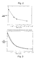
figure 2 shows a diagram which relates a certain number of stress cycles measured with certain amplitude values; and -
figure 3 shows a comparison between the values offigure 2 and the function obtained by approximating these values by means of an exponential regression. - With reference in particular to
figure 1 , this schematically shows a generic gas turbine, comprising acompressor 10 capable of compressing air introduced through aninlet duct 12. The compressed air is then sent to acombustion chamber 14 to be mixed with gaseous fuel coming from asupply duct 16. The combustion increases the temperature, the rate and volume of the gas flow and consequently of the energy contained therein. This gas flow is directed, through aduct 18, towards aturbine 20, which transforms the gas energy into work energy which can be exploited for activating operating machines, such as for example agenerator 22 connected to theturbine 20 by means of ashaft 24. Theturbine 20 also supplies the energy necessary for activating thecompressor 10 through therelative shaft 26, whereas the exhaust gases are expelled by theturbine 20 through anoutlet duct 28. - The method for controlling the pressure dynamics and for estimating the life cycle of the
combustion chamber 14 according to the present invention envisages the correlation between the stress amplitudes, due to the increases in pressure which take place inside thecombustion chamber 14 itself, and the persistence times (cycles) of said stress through the well-known Wohler curve. - The Wohler curve is a graph on a statistic basis which relates the maximum amplitude of a fatigue cycle with the number of cycles which a certain material tolerates before breakage with a pre-established probability. Its construction is effected by reconstructing a certain stress cycle in the laboratory with a certain amplitude which is applied to a high number of test-samples, registering the number of cycles they tolerate before breakage. Although the test-samples are subjected to the same stress, they do not all break after the same number of cycles but there is a dispersion of the results. Experience shows that this dispersion takes place according to a normal distribution. The same series of experiments is then repeated at different amplitude values and, for each distribution obtained, the average value of the number of cycles before breakage is registered.
- The curve which joins all the average values at each stress amplitude is the Wohler curve at 50% probability of breakage. This means that, with respect to the samples tested, there is a 50% probability that, when subjected to a stress cycle of a certain amplitude, they will break before reaching the number of cycles delimited by the Wohler curve.
- The method according to the invention then envisages a series of tests, using one or
more probes 30 situated in correspondence with thecombustion chamber 14, for the direct measurement in real time of the amplitude of the pressure oscillations inside thecombustion chamber 14 itself. The measurements are used for determining the "cumulative stress", i.e. the amount of time which has lapsed over each significant amplitude level. The fatigue life cycle which has already passed is calculated by means of the well-known Palmgren-Miner hypothesis, considering all the amplitudes and relative consumptions of the fatigue life cycle. - When the cumulative damage D, defined below, exceeds a certain predefined value, a command is given to switch off the turbine and an inspection of the plant is effected. In this way, considering all the contributions of all the amplitudes of the fatigue cycles, a correct estimation of the residual fatigue life cycle can be obtained.
- Operationally, according to an application example of the method according to the invention, the behaviour of the
combustion chamber 14 is evaluated under fatigue conditions, by constructing the Wohler curve for a certain material which forms thecombustion chamber 14 and for a combustion frequency of 400 Hz. Four points are identified for four different amplitude levels, from peak to peak, which allow a draft Wohler curve to be constructed (figure 2 ) on the basis of the following data:102 min 2 2.4x10⁶ 45 min 3 1.08x10⁶ Duration 30 min Amplitude 4 Cycles 7.2x10⁵ 2 min 8 4.8x10⁴ - In order to measure the cumulative damage D to the
combustion chamber 14 during functioning under fatigue conditions of the turbine, the Palmgren-Miner hypothesis is used, which asserts that the fraction of damage at any tension level is linearly proportional to the ratio between the number of functioning cycles and the total number of cycles which would produce the yield to that level of tension, i.e.:
wherein the term D represents the cumulative damage, the term Ni represents the residual life and derives from the Wohler curve and the term ni is measured. k indicates the number of amplitude levels, Ni is the number of cycles necessary for reaching breakage at the i-th level of amplitude and ni is the number of cycles which have passed at the i-th level of amplitude. - The values indicated in
figure 2 can be approximated with an exponential regression of the values of the cycles and amplitudes, as can be seen in the graph offigure 3 , obtaining the following resulting function: F (x) := 6.651 · exp (-1.583· 10-6· x) + 1.839 - In order to determine the values of Ni , it is necessary to calculate the inverse function, i.e.: y=6.651·exp(1.583·106·x)+1.839solve,x→(631711.93935565382186)· In(.1503533303262667 2681·y-.27649977447000451060) g(y):=(631711.93935565382186).ln(.15035333032626672681·y-.276499774470004510 60)
- A vector is therefore created which represents the residual life, in terms of cycles, for the different amplitudes considered:
g(2) 2.351x10⁶ g(3) 1.103x10⁶ g(4) 7.102x10⁵ Life = g(5) Life = 4.699x10⁵ g(6) 2.963x10⁵ g(7) 1.602x10⁵ g(8) 4.834x10⁴ - The residual life of the
combustor 14 is therefore represented by a vector containing the values of Ni obtained by means of the Palmgren-Miner hypothesis. At this point, a meter measures the time which has passed between two consecutive amplitude levels i and i+1, for example equal to pressure values of 2 psi and 3 psi. The time interval measured is then attributed to the i-th of amplitude level and is multiplied by 400 Hz to obtain the value of ni at the (i+1)-th level. By dividing ni by Ni and effecting the sum, the value of the cumulative damage D is finally obtained. - A threshold value equal to 0.1 is established for the cumulative damage D. When D exceeds this threshold value, the turbine is put under diffusion flame operational conditions, i.e. a type of functioning with lower pressure oscillation levels inside the
combustion chamber 14 but with greater polluting emissions. - According to a preferred application example, the control software of the turbine is capable of directly using the continuous function g(y) for the calculation of the residual life, without the necessity of discretizing the residual life vector previously exposed.
- It can thus be seen that the method for controlling the pressure dynamics and estimating the life cycle of the combustion chamber of a gas turbine according to the present invention achieves the objectives previously specified, as it allows a correct evaluation of the residual fatigue life of the combustion chamber to improve the performances of the turbine, allowing specific protection actions to be undertaken only when strictly necessary.
- The method for controlling the pressure dynamics and estimating the life cycle of the combustion chamber of a gas turbine according to the present invention thus conceived can in any case undergo numerous modifications and variants, all included in the same inventive concept. The protection scope of the invention is therefore defined by the enclosed claims.
Claims (4)
- A method for controlling the combustion in a gas turbine of the type comprising at least one compressor (10), capable of compressing air introduced therein through an inlet duct (12), at least one combustion chamber (14), where said compressed air is mixed with a gaseous fuel coming from a supply duct (16), and at least one turbine (20), capable of transforming the energy of the gas coming from said combustion chamber (14) into work energy which can be exploited for activating one or more operating machines (22), the method comprising:• measuring, by means of one or more probes (30) situated in correspondence with said combustion chamber (14), the amplitude of the pressure oscillations inside the combustion chamber (14) and the persistence time or cycle of the same oscillations;• evaluating the behaviour under fatigue conditions of said combustion chamber (14), by constructing the Wohler curve for a certain material which forms said combustion chamber (14), for a predefined combustion frequency and for said amplitude and cycle values of the measured pressure oscillations ;• measuring the cumulative damage (D) to said combustion chamber (14) during functioning under fatigue conditions of said turbine by means of the Palmgren-Miner hypothesis, said Palmgren-Miner hypothesis being defined as:

wherein: D = cumulative damage;k = number of amplitude levels;Ni = number of cycles necessary for reaching breakage at the i-th level of amplitude, deriving from said Wohler curve;ni is the number of cycles which have passed at the i-th level of amplitude.• undertaking protection actions of said turbine if the cumulative damage value (D) measured is exceeded - The method according to claim 1, further comprising: approximating, with an exponential regression f(x), said values of the cycles and amplitudes measured.
- The method according to claim 1 or claim 2, further comprising:calculating the inverse function g(x) of said exponential regression f(x) for determining said number of cycles (Ni).
- The method according to any one of the preceding claims, wherein said undertaking comprises putting said turbine under diffusion flame operational conditions and reducing the pressure oscillations inside said combustion chamber (14).
Applications Claiming Priority (1)
| Application Number | Priority Date | Filing Date | Title |
|---|---|---|---|
| IT001048A ITMI20071048A1 (en) | 2007-05-23 | 2007-05-23 | METHOD FOR THE CONTROL OF THE PRESSURE DYNAMICS AND FOR THE ESTIMATE OF THE LIFE CYCLE OF THE COMBUSTION CHAMBER OF A GAS TURBINE |
Publications (3)
| Publication Number | Publication Date |
|---|---|
| EP1995519A2 true EP1995519A2 (en) | 2008-11-26 |
| EP1995519A3 EP1995519A3 (en) | 2017-07-26 |
| EP1995519B1 EP1995519B1 (en) | 2020-04-08 |
Family
ID=39642964
Family Applications (1)
| Application Number | Title | Priority Date | Filing Date |
|---|---|---|---|
| EP08156638.2A Active EP1995519B1 (en) | 2007-05-23 | 2008-05-21 | Method for controlling the pressure dynamics and for estimating the life cycle of the combustion chamber of a gas turbine |
Country Status (8)
| Country | Link |
|---|---|
| US (1) | US8868313B2 (en) |
| EP (1) | EP1995519B1 (en) |
| JP (1) | JP5290625B2 (en) |
| KR (1) | KR101457696B1 (en) |
| CN (1) | CN101311510B (en) |
| CA (1) | CA2630953C (en) |
| IT (1) | ITMI20071048A1 (en) |
| RU (1) | RU2465519C2 (en) |
Cited By (1)
| Publication number | Priority date | Publication date | Assignee | Title |
|---|---|---|---|---|
| EP2520863A1 (en) | 2011-05-05 | 2012-11-07 | Alstom Technology Ltd | Method for protecting a gas turbine engine against high dynamical process values and gas turbine engine for conducting said method |
Families Citing this family (7)
| Publication number | Priority date | Publication date | Assignee | Title |
|---|---|---|---|---|
| US8924506B2 (en) | 2000-12-27 | 2014-12-30 | Bradium Technologies Llc | Optimized image delivery over limited bandwidth communication channels |
| US8370046B2 (en) * | 2010-02-11 | 2013-02-05 | General Electric Company | System and method for monitoring a gas turbine |
| US8437880B2 (en) * | 2010-05-17 | 2013-05-07 | General Electric Company | System and method for enhancement of power generation facilities |
| KR20150047497A (en) * | 2012-08-30 | 2015-05-04 | 지멘스 악티엔게젤샤프트 | Method for monitoring the operation of a gas turbine |
| CN105973597B (en) * | 2016-05-27 | 2019-04-09 | 北京交通大学 | Test Prediction Method of Train Axlebox Bearing Life |
| US11016117B2 (en) | 2018-08-31 | 2021-05-25 | Honeywell International Inc. | Air data probe replacement determination system |
| US11422153B2 (en) | 2020-01-24 | 2022-08-23 | Honeywell International Inc. | Air data probe replacement determination system |
Family Cites Families (28)
| Publication number | Priority date | Publication date | Assignee | Title |
|---|---|---|---|---|
| US3651639A (en) * | 1969-12-29 | 1972-03-28 | Avco Corp | Error compensated fluidic temperature sensor |
| DE2314954C3 (en) * | 1973-03-26 | 1982-08-26 | Brown, Boveri & Cie Ag, 6800 Mannheim | Arrangement for the ongoing determination and monitoring of the service life of thermally loaded thick-walled components |
| US5042295A (en) * | 1985-06-21 | 1991-08-27 | General Electric Company | Method for determining remaining useful life of turbine components |
| US5148667A (en) * | 1990-02-01 | 1992-09-22 | Electric Power Research Institute | Gas turbine flame diagnostic monitor |
| US6082092A (en) * | 1998-04-08 | 2000-07-04 | General Electric Co. | Combustion dynamics control for variable fuel gas composition and temperature based on gas control valve feedback |
| RU2145718C1 (en) * | 1999-01-21 | 2000-02-20 | НПО измерительной техники | Method for diagnosing abnormal operating conditions of jet engines |
| US6449565B1 (en) * | 1999-04-05 | 2002-09-10 | United Technologies Corporation | Method and apparatus for determining in real-time the fatigue life of a structure |
| JP3910339B2 (en) * | 2000-05-17 | 2007-04-25 | 株式会社日立製作所 | Gas turbine, fatigue diagnosis apparatus thereof, and fatigue diagnosis method thereof |
| SE517970C2 (en) * | 2000-07-20 | 2002-08-13 | Volvo Articulated Haulers Ab | Procedure for Estimating a Lifetime Reducing Damage to an Operationally Loaded Object, as well as Computer Software Product |
| DE50115614D1 (en) * | 2001-04-17 | 2010-10-14 | Alstom Technology Ltd | Method for suppressing combustion fluctuations in a gas turbine |
| EP1262638A1 (en) * | 2001-05-31 | 2002-12-04 | Siemens Aktiengesellschaft | Device for cooling of the cooling fluid of a gas turbine and gas and steam turbine plant with such a device |
| EP1270874B1 (en) * | 2001-06-18 | 2005-08-31 | Siemens Aktiengesellschaft | Gas turbine with an air compressor |
| EP1275821A1 (en) * | 2001-07-12 | 2003-01-15 | Siemens Aktiengesellschaft | Method of operating a steam power plant and corresponding power plant |
| DE10138013B4 (en) * | 2001-08-02 | 2006-12-14 | Man B & W Diesel Ag | Device for monitoring a compressor wheel |
| DE10211141A1 (en) * | 2002-03-14 | 2003-09-25 | Alstom Switzerland Ltd | Method for igniting the combustion chamber of a gas turbine system and ignition device for carrying out the method |
| EP1542331A4 (en) * | 2002-08-21 | 2010-01-20 | Ebara Corp | POWER SUPPLY SYSTEM |
| SE522132C2 (en) * | 2002-12-13 | 2004-01-13 | Gas Turbine Efficiency Ab | Cleaning method for stationary gas turbine unit in operation, by spraying cleaning fluid into point in air inlet channel where air velocity has specific minimum value |
| US6993960B2 (en) * | 2002-12-26 | 2006-02-07 | Woodward Governor Company | Method and apparatus for detecting combustion instability in continuous combustion systems |
| RU2236671C1 (en) * | 2003-04-14 | 2004-09-20 | Открытое акционерное общество "Научно-производственное объединение "Сатурн" | Method of operation of aircraft gas-turbine engine according to its technical state |
| JP3837124B2 (en) * | 2003-05-09 | 2006-10-25 | 川崎重工業株式会社 | Information acquisition device and evaluation equipment |
| JP4091874B2 (en) * | 2003-05-21 | 2008-05-28 | 本田技研工業株式会社 | Secondary air supply device for gas turbine engine |
| JP3872772B2 (en) * | 2003-06-18 | 2007-01-24 | 三菱重工業株式会社 | Combustion management system with fuel switching function and combustion management method |
| JP2005098258A (en) * | 2003-09-26 | 2005-04-14 | Hitachi Ltd | Turbine generator shaft torsional vibration detection method |
| US20050273277A1 (en) * | 2004-01-14 | 2005-12-08 | University Of Tennessee Research Foundation, Inc. | Vehicle fatigue life and durability monitoring system and methodology |
| EP1688671B2 (en) * | 2005-02-03 | 2019-01-09 | Ansaldo Energia IP UK Limited | Protection method and control system for a gas turbine |
| DE602005001611T2 (en) * | 2005-02-04 | 2008-03-13 | Enel Produzione S.P.A. | Damping of thermoacoustic oscillations in a gas turbine combustor with annular chamber |
| SE531872C2 (en) * | 2006-01-24 | 2009-09-01 | Bengt H Nilsson Med Ultirec Fa | Procedure for incremental energy conversion |
| US7805329B2 (en) * | 2006-03-02 | 2010-09-28 | Siemens Aktiengesellschaft | Development of actual risk costs based on estimated risk costs as well as probabilistic restriction of the actual risk costs |
-
2007
- 2007-05-23 IT IT001048A patent/ITMI20071048A1/en unknown
-
2008
- 2008-04-07 US US12/098,563 patent/US8868313B2/en not_active Expired - Fee Related
- 2008-05-08 CA CA2630953A patent/CA2630953C/en active Active
- 2008-05-21 EP EP08156638.2A patent/EP1995519B1/en active Active
- 2008-05-21 JP JP2008132584A patent/JP5290625B2/en not_active Expired - Fee Related
- 2008-05-22 RU RU2008120462/06A patent/RU2465519C2/en active
- 2008-05-22 KR KR1020080047721A patent/KR101457696B1/en not_active Expired - Fee Related
- 2008-05-23 CN CN2008101091074A patent/CN101311510B/en not_active Expired - Fee Related
Cited By (2)
| Publication number | Priority date | Publication date | Assignee | Title |
|---|---|---|---|---|
| EP2520863A1 (en) | 2011-05-05 | 2012-11-07 | Alstom Technology Ltd | Method for protecting a gas turbine engine against high dynamical process values and gas turbine engine for conducting said method |
| US9068512B2 (en) | 2011-05-05 | 2015-06-30 | Alstom Technology Ltd. | Method for protecting a gas turbine engine against high dynamical process values and gas turbine engine for conducting the method |
Also Published As
| Publication number | Publication date |
|---|---|
| KR101457696B1 (en) | 2014-11-03 |
| JP2008291842A (en) | 2008-12-04 |
| EP1995519A3 (en) | 2017-07-26 |
| ITMI20071048A1 (en) | 2008-11-24 |
| CN101311510B (en) | 2013-06-19 |
| US20080294322A1 (en) | 2008-11-27 |
| RU2465519C2 (en) | 2012-10-27 |
| CA2630953A1 (en) | 2008-11-23 |
| CA2630953C (en) | 2015-07-21 |
| CN101311510A (en) | 2008-11-26 |
| KR20080103446A (en) | 2008-11-27 |
| EP1995519B1 (en) | 2020-04-08 |
| US8868313B2 (en) | 2014-10-21 |
| JP5290625B2 (en) | 2013-09-18 |
| RU2008120462A (en) | 2009-11-27 |
Similar Documents
| Publication | Publication Date | Title |
|---|---|---|
| EP1995519B1 (en) | Method for controlling the pressure dynamics and for estimating the life cycle of the combustion chamber of a gas turbine | |
| US12305853B2 (en) | Integrated flare combustion control | |
| CN101779020B (en) | Gas turbine control method and device | |
| US7194382B2 (en) | Systems and methods for detection of combustor stability margin | |
| CN101595288A (en) | Method and system for monitoring process status of an internal combustion engine | |
| CN107145641A (en) | Blade vibration fatigue Probabilistic Life Prediction method | |
| CN108663198A (en) | Test system for turbine blades | |
| CA2891736C (en) | Gas turbine fuel supply method and arrangement | |
| Stadlmair et al. | Thermoacoustic damping rate determination from combustion noise using bayesian statistics | |
| JP4562108B2 (en) | Method for online measurement of fuel thermal function of fuel in a combustion turbine unit | |
| US6694742B2 (en) | Gas turbine system operation based on estimated stress | |
| EP1983338A2 (en) | Method for monitoring emissions of NOx from an emission source | |
| EP2865865B1 (en) | Method and system for gas turbine power augmentation using steam injection | |
| AU2015359745B2 (en) | Method of controlling a test apparatus for a gas turbine engine and test apparatus | |
| JP2000130750A (en) | Combustion monitoring device | |
| JP7106266B2 (en) | Model-less combustion dynamics automatic tuning | |
| US20220220904A1 (en) | Method for controlling a gas turbine | |
| Kilicarslan et al. | Acoustic analysis of a liquefied petroleum gas-fired pulse combustor | |
| JP4331859B2 (en) | Device life prediction method under narrow-band random stress fluctuation | |
| Weidner et al. | Pulsations in Gas Turbine Operation: Identification and Modeling With the Purpose of Online Engine Monitoring and Optimization | |
| EP2828491A1 (en) | Gas turbine having fuel monitoring | |
| Lieuwen | Online combustor stability margin assessment using dynamic pressure data | |
| Patriarca et al. | Acceptability of defects under Combined Cycle Fatigue for a precipitation hardened steel | |
| Freitag et al. | Prediction of the Stability Behaviour of a Combustor using a Low Order Model and Measured Flame Transfer Functions (8th APISCEU) | |
| JP2005180954A (en) | Pressure durability test method and its device |
Legal Events
| Date | Code | Title | Description |
|---|---|---|---|
| PUAI | Public reference made under article 153(3) epc to a published international application that has entered the european phase |
Free format text: ORIGINAL CODE: 0009012 |
|
| AK | Designated contracting states |
Kind code of ref document: A2 Designated state(s): AT BE BG CH CY CZ DE DK EE ES FI FR GB GR HR HU IE IS IT LI LT LU LV MC MT NL NO PL PT RO SE SI SK TR |
|
| AX | Request for extension of the european patent |
Extension state: AL BA MK RS |
|
| PUAL | Search report despatched |
Free format text: ORIGINAL CODE: 0009013 |
|
| RIC1 | Information provided on ipc code assigned before grant |
Ipc: F23N 5/00 20060101ALI20170522BHEP Ipc: F23N 3/00 20060101AFI20170522BHEP |
|
| RIC1 | Information provided on ipc code assigned before grant |
Ipc: F23N 3/00 20060101AFI20170601BHEP Ipc: F23N 5/00 20060101ALI20170601BHEP |
|
| AK | Designated contracting states |
Kind code of ref document: A3 Designated state(s): AT BE BG CH CY CZ DE DK EE ES FI FR GB GR HR HU IE IS IT LI LT LU LV MC MT NL NO PL PT RO SE SI SK TR |
|
| AX | Request for extension of the european patent |
Extension state: AL BA MK RS |
|
| RIC1 | Information provided on ipc code assigned before grant |
Ipc: F23N 5/00 20060101ALI20170706BHEP Ipc: F23N 3/00 20060101AFI20170706BHEP |
|
| STAA | Information on the status of an ep patent application or granted ep patent |
Free format text: STATUS: REQUEST FOR EXAMINATION WAS MADE |
|
| 17P | Request for examination filed |
Effective date: 20180126 |
|
| RBV | Designated contracting states (corrected) |
Designated state(s): AT BE BG CH CY CZ DE DK EE ES FI FR GB GR HR HU IE IS IT LI LT LU LV MC MT NL NO PL PT RO SE SI SK TR |
|
| AKX | Designation fees paid |
Designated state(s): AT BE BG CH CY CZ DE DK EE ES FI FR GB GR HR HU IE IS IT LI LT LU LV MC MT NL NO PL PT RO SE SI SK TR |
|
| AXX | Extension fees paid |
Extension state: AL Extension state: BA Extension state: MK Extension state: RS |
|
| STAA | Information on the status of an ep patent application or granted ep patent |
Free format text: STATUS: EXAMINATION IS IN PROGRESS |
|
| 17Q | First examination report despatched |
Effective date: 20180507 |
|
| GRAP | Despatch of communication of intention to grant a patent |
Free format text: ORIGINAL CODE: EPIDOSNIGR1 |
|
| STAA | Information on the status of an ep patent application or granted ep patent |
Free format text: STATUS: GRANT OF PATENT IS INTENDED |
|
| INTG | Intention to grant announced |
Effective date: 20191016 |
|
| GRAS | Grant fee paid |
Free format text: ORIGINAL CODE: EPIDOSNIGR3 |
|
| GRAA | (expected) grant |
Free format text: ORIGINAL CODE: 0009210 |
|
| STAA | Information on the status of an ep patent application or granted ep patent |
Free format text: STATUS: THE PATENT HAS BEEN GRANTED |
|
| AK | Designated contracting states |
Kind code of ref document: B1 Designated state(s): AT BE BG CH CY CZ DE DK EE ES FI FR GB GR HR HU IE IS IT LI LT LU LV MC MT NL NO PL PT RO SE SI SK TR |
|
| REG | Reference to a national code |
Ref country code: GB Ref legal event code: FG4D |
|
| REG | Reference to a national code |
Ref country code: CH Ref legal event code: EP Ref country code: AT Ref legal event code: REF Ref document number: 1254886 Country of ref document: AT Kind code of ref document: T Effective date: 20200415 |
|
| REG | Reference to a national code |
Ref country code: DE Ref legal event code: R096 Ref document number: 602008062467 Country of ref document: DE |
|
| REG | Reference to a national code |
Ref country code: IE Ref legal event code: FG4D |
|
| REG | Reference to a national code |
Ref country code: NO Ref legal event code: T2 Effective date: 20200408 |
|
| REG | Reference to a national code |
Ref country code: NL Ref legal event code: MP Effective date: 20200408 |
|
| REG | Reference to a national code |
Ref country code: LT Ref legal event code: MG4D |
|
| PG25 | Lapsed in a contracting state [announced via postgrant information from national office to epo] |
Ref country code: IS Free format text: LAPSE BECAUSE OF FAILURE TO SUBMIT A TRANSLATION OF THE DESCRIPTION OR TO PAY THE FEE WITHIN THE PRESCRIBED TIME-LIMIT Effective date: 20200808 Ref country code: PT Free format text: LAPSE BECAUSE OF FAILURE TO SUBMIT A TRANSLATION OF THE DESCRIPTION OR TO PAY THE FEE WITHIN THE PRESCRIBED TIME-LIMIT Effective date: 20200817 Ref country code: GR Free format text: LAPSE BECAUSE OF FAILURE TO SUBMIT A TRANSLATION OF THE DESCRIPTION OR TO PAY THE FEE WITHIN THE PRESCRIBED TIME-LIMIT Effective date: 20200709 Ref country code: FI Free format text: LAPSE BECAUSE OF FAILURE TO SUBMIT A TRANSLATION OF THE DESCRIPTION OR TO PAY THE FEE WITHIN THE PRESCRIBED TIME-LIMIT Effective date: 20200408 Ref country code: SE Free format text: LAPSE BECAUSE OF FAILURE TO SUBMIT A TRANSLATION OF THE DESCRIPTION OR TO PAY THE FEE WITHIN THE PRESCRIBED TIME-LIMIT Effective date: 20200408 Ref country code: LT Free format text: LAPSE BECAUSE OF FAILURE TO SUBMIT A TRANSLATION OF THE DESCRIPTION OR TO PAY THE FEE WITHIN THE PRESCRIBED TIME-LIMIT Effective date: 20200408 Ref country code: NL Free format text: LAPSE BECAUSE OF FAILURE TO SUBMIT A TRANSLATION OF THE DESCRIPTION OR TO PAY THE FEE WITHIN THE PRESCRIBED TIME-LIMIT Effective date: 20200408 |
|
| RAP2 | Party data changed (patent owner data changed or rights of a patent transferred) |
Owner name: NUOVO PIGNONE INTERNATIONAL S.R.L. |
|
| PG25 | Lapsed in a contracting state [announced via postgrant information from national office to epo] |
Ref country code: BG Free format text: LAPSE BECAUSE OF FAILURE TO SUBMIT A TRANSLATION OF THE DESCRIPTION OR TO PAY THE FEE WITHIN THE PRESCRIBED TIME-LIMIT Effective date: 20200708 Ref country code: LV Free format text: LAPSE BECAUSE OF FAILURE TO SUBMIT A TRANSLATION OF THE DESCRIPTION OR TO PAY THE FEE WITHIN THE PRESCRIBED TIME-LIMIT Effective date: 20200408 Ref country code: HR Free format text: LAPSE BECAUSE OF FAILURE TO SUBMIT A TRANSLATION OF THE DESCRIPTION OR TO PAY THE FEE WITHIN THE PRESCRIBED TIME-LIMIT Effective date: 20200408 |
|
| REG | Reference to a national code |
Ref country code: DE Ref legal event code: R097 Ref document number: 602008062467 Country of ref document: DE |
|
| PG25 | Lapsed in a contracting state [announced via postgrant information from national office to epo] |
Ref country code: CH Free format text: LAPSE BECAUSE OF NON-PAYMENT OF DUE FEES Effective date: 20200531 Ref country code: DK Free format text: LAPSE BECAUSE OF FAILURE TO SUBMIT A TRANSLATION OF THE DESCRIPTION OR TO PAY THE FEE WITHIN THE PRESCRIBED TIME-LIMIT Effective date: 20200408 Ref country code: EE Free format text: LAPSE BECAUSE OF FAILURE TO SUBMIT A TRANSLATION OF THE DESCRIPTION OR TO PAY THE FEE WITHIN THE PRESCRIBED TIME-LIMIT Effective date: 20200408 Ref country code: MC Free format text: LAPSE BECAUSE OF FAILURE TO SUBMIT A TRANSLATION OF THE DESCRIPTION OR TO PAY THE FEE WITHIN THE PRESCRIBED TIME-LIMIT Effective date: 20200408 Ref country code: CZ Free format text: LAPSE BECAUSE OF FAILURE TO SUBMIT A TRANSLATION OF THE DESCRIPTION OR TO PAY THE FEE WITHIN THE PRESCRIBED TIME-LIMIT Effective date: 20200408 Ref country code: IT Free format text: LAPSE BECAUSE OF FAILURE TO SUBMIT A TRANSLATION OF THE DESCRIPTION OR TO PAY THE FEE WITHIN THE PRESCRIBED TIME-LIMIT Effective date: 20200408 Ref country code: RO Free format text: LAPSE BECAUSE OF FAILURE TO SUBMIT A TRANSLATION OF THE DESCRIPTION OR TO PAY THE FEE WITHIN THE PRESCRIBED TIME-LIMIT Effective date: 20200408 Ref country code: LI Free format text: LAPSE BECAUSE OF NON-PAYMENT OF DUE FEES Effective date: 20200531 Ref country code: ES Free format text: LAPSE BECAUSE OF FAILURE TO SUBMIT A TRANSLATION OF THE DESCRIPTION OR TO PAY THE FEE WITHIN THE PRESCRIBED TIME-LIMIT Effective date: 20200408 |
|
| PLBE | No opposition filed within time limit |
Free format text: ORIGINAL CODE: 0009261 |
|
| STAA | Information on the status of an ep patent application or granted ep patent |
Free format text: STATUS: NO OPPOSITION FILED WITHIN TIME LIMIT |
|
| PG25 | Lapsed in a contracting state [announced via postgrant information from national office to epo] |
Ref country code: PL Free format text: LAPSE BECAUSE OF FAILURE TO SUBMIT A TRANSLATION OF THE DESCRIPTION OR TO PAY THE FEE WITHIN THE PRESCRIBED TIME-LIMIT Effective date: 20200408 Ref country code: SK Free format text: LAPSE BECAUSE OF FAILURE TO SUBMIT A TRANSLATION OF THE DESCRIPTION OR TO PAY THE FEE WITHIN THE PRESCRIBED TIME-LIMIT Effective date: 20200408 |
|
| 26N | No opposition filed |
Effective date: 20210112 |
|
| REG | Reference to a national code |
Ref country code: BE Ref legal event code: MM Effective date: 20200531 |
|
| GBPC | Gb: european patent ceased through non-payment of renewal fee |
Effective date: 20200708 |
|
| PG25 | Lapsed in a contracting state [announced via postgrant information from national office to epo] |
Ref country code: LU Free format text: LAPSE BECAUSE OF NON-PAYMENT OF DUE FEES Effective date: 20200521 |
|
| PG25 | Lapsed in a contracting state [announced via postgrant information from national office to epo] |
Ref country code: FR Free format text: LAPSE BECAUSE OF NON-PAYMENT OF DUE FEES Effective date: 20200608 Ref country code: GB Free format text: LAPSE BECAUSE OF NON-PAYMENT OF DUE FEES Effective date: 20200708 Ref country code: IE Free format text: LAPSE BECAUSE OF NON-PAYMENT OF DUE FEES Effective date: 20200521 |
|
| PG25 | Lapsed in a contracting state [announced via postgrant information from national office to epo] |
Ref country code: BE Free format text: LAPSE BECAUSE OF NON-PAYMENT OF DUE FEES Effective date: 20200531 Ref country code: SI Free format text: LAPSE BECAUSE OF FAILURE TO SUBMIT A TRANSLATION OF THE DESCRIPTION OR TO PAY THE FEE WITHIN THE PRESCRIBED TIME-LIMIT Effective date: 20200408 |
|
| PGFP | Annual fee paid to national office [announced via postgrant information from national office to epo] |
Ref country code: DE Payment date: 20210421 Year of fee payment: 14 Ref country code: NO Payment date: 20210422 Year of fee payment: 14 |
|
| PGFP | Annual fee paid to national office [announced via postgrant information from national office to epo] |
Ref country code: AT Payment date: 20210422 Year of fee payment: 14 |
|
| PG25 | Lapsed in a contracting state [announced via postgrant information from national office to epo] |
Ref country code: TR Free format text: LAPSE BECAUSE OF FAILURE TO SUBMIT A TRANSLATION OF THE DESCRIPTION OR TO PAY THE FEE WITHIN THE PRESCRIBED TIME-LIMIT Effective date: 20200408 Ref country code: MT Free format text: LAPSE BECAUSE OF FAILURE TO SUBMIT A TRANSLATION OF THE DESCRIPTION OR TO PAY THE FEE WITHIN THE PRESCRIBED TIME-LIMIT Effective date: 20200408 Ref country code: CY Free format text: LAPSE BECAUSE OF FAILURE TO SUBMIT A TRANSLATION OF THE DESCRIPTION OR TO PAY THE FEE WITHIN THE PRESCRIBED TIME-LIMIT Effective date: 20200408 |
|
| REG | Reference to a national code |
Ref country code: DE Ref legal event code: R119 Ref document number: 602008062467 Country of ref document: DE |
|
| REG | Reference to a national code |
Ref country code: NO Ref legal event code: MMEP |
|
| REG | Reference to a national code |
Ref country code: AT Ref legal event code: MM01 Ref document number: 1254886 Country of ref document: AT Kind code of ref document: T Effective date: 20220521 |
|
| PG25 | Lapsed in a contracting state [announced via postgrant information from national office to epo] |
Ref country code: NO Free format text: LAPSE BECAUSE OF NON-PAYMENT OF DUE FEES Effective date: 20220531 Ref country code: AT Free format text: LAPSE BECAUSE OF NON-PAYMENT OF DUE FEES Effective date: 20220521 |
|
| REG | Reference to a national code |
Ref country code: AT Ref legal event code: UEP Ref document number: 1254886 Country of ref document: AT Kind code of ref document: T Effective date: 20200408 |
|
| PG25 | Lapsed in a contracting state [announced via postgrant information from national office to epo] |
Ref country code: DE Free format text: LAPSE BECAUSE OF NON-PAYMENT OF DUE FEES Effective date: 20221201 |