EP1995513A1 - Verfahren zur Montage einer LED-Leuchte - Google Patents
Verfahren zur Montage einer LED-Leuchte Download PDFInfo
- Publication number
- EP1995513A1 EP1995513A1 EP20080101709 EP08101709A EP1995513A1 EP 1995513 A1 EP1995513 A1 EP 1995513A1 EP 20080101709 EP20080101709 EP 20080101709 EP 08101709 A EP08101709 A EP 08101709A EP 1995513 A1 EP1995513 A1 EP 1995513A1
- Authority
- EP
- European Patent Office
- Prior art keywords
- led module
- optical unit
- led
- relative
- electromagnetic radiation
- Prior art date
- Legal status (The legal status is an assumption and is not a legal conclusion. Google has not performed a legal analysis and makes no representation as to the accuracy of the status listed.)
- Granted
Links
Images
Classifications
-
- F—MECHANICAL ENGINEERING; LIGHTING; HEATING; WEAPONS; BLASTING
- F21—LIGHTING
- F21V—FUNCTIONAL FEATURES OR DETAILS OF LIGHTING DEVICES OR SYSTEMS THEREOF; STRUCTURAL COMBINATIONS OF LIGHTING DEVICES WITH OTHER ARTICLES, NOT OTHERWISE PROVIDED FOR
- F21V17/00—Fastening of component parts of lighting devices, e.g. shades, globes, refractors, reflectors, filters, screens, grids or protective cages
- F21V17/10—Fastening of component parts of lighting devices, e.g. shades, globes, refractors, reflectors, filters, screens, grids or protective cages characterised by specific fastening means or way of fastening
- F21V17/101—Fastening of component parts of lighting devices, e.g. shades, globes, refractors, reflectors, filters, screens, grids or protective cages characterised by specific fastening means or way of fastening permanently, e.g. welding, gluing or riveting
-
- B—PERFORMING OPERATIONS; TRANSPORTING
- B60—VEHICLES IN GENERAL
- B60Q—ARRANGEMENT OF SIGNALLING OR LIGHTING DEVICES, THE MOUNTING OR SUPPORTING THEREOF OR CIRCUITS THEREFOR, FOR VEHICLES IN GENERAL
- B60Q3/00—Arrangement of lighting devices for vehicle interiors; Lighting devices specially adapted for vehicle interiors
- B60Q3/40—Arrangement of lighting devices for vehicle interiors; Lighting devices specially adapted for vehicle interiors specially adapted for specific vehicle types
- B60Q3/41—Arrangement of lighting devices for vehicle interiors; Lighting devices specially adapted for vehicle interiors specially adapted for specific vehicle types for mass transit vehicles, e.g. buses
- B60Q3/44—Spotlighting, e.g. reading lamps
-
- B—PERFORMING OPERATIONS; TRANSPORTING
- B60—VEHICLES IN GENERAL
- B60Q—ARRANGEMENT OF SIGNALLING OR LIGHTING DEVICES, THE MOUNTING OR SUPPORTING THEREOF OR CIRCUITS THEREFOR, FOR VEHICLES IN GENERAL
- B60Q3/00—Arrangement of lighting devices for vehicle interiors; Lighting devices specially adapted for vehicle interiors
- B60Q3/70—Arrangement of lighting devices for vehicle interiors; Lighting devices specially adapted for vehicle interiors characterised by the purpose
- B60Q3/76—Arrangement of lighting devices for vehicle interiors; Lighting devices specially adapted for vehicle interiors characterised by the purpose for spotlighting, e.g. reading lamps
-
- F—MECHANICAL ENGINEERING; LIGHTING; HEATING; WEAPONS; BLASTING
- F21—LIGHTING
- F21K—NON-ELECTRIC LIGHT SOURCES USING LUMINESCENCE; LIGHT SOURCES USING ELECTROCHEMILUMINESCENCE; LIGHT SOURCES USING CHARGES OF COMBUSTIBLE MATERIAL; LIGHT SOURCES USING SEMICONDUCTOR DEVICES AS LIGHT-GENERATING ELEMENTS; LIGHT SOURCES NOT OTHERWISE PROVIDED FOR
- F21K9/00—Light sources using semiconductor devices as light-generating elements, e.g. using light-emitting diodes [LED] or lasers
-
- F—MECHANICAL ENGINEERING; LIGHTING; HEATING; WEAPONS; BLASTING
- F21—LIGHTING
- F21V—FUNCTIONAL FEATURES OR DETAILS OF LIGHTING DEVICES OR SYSTEMS THEREOF; STRUCTURAL COMBINATIONS OF LIGHTING DEVICES WITH OTHER ARTICLES, NOT OTHERWISE PROVIDED FOR
- F21V7/00—Reflectors for light sources
- F21V7/0066—Reflectors for light sources specially adapted to cooperate with point like light sources; specially adapted to cooperate with light sources the shape of which is unspecified
-
- G—PHYSICS
- G02—OPTICS
- G02B—OPTICAL ELEMENTS, SYSTEMS OR APPARATUS
- G02B27/00—Optical systems or apparatus not provided for by any of the groups G02B1/00 - G02B26/00, G02B30/00
- G02B27/62—Optical apparatus specially adapted for adjusting optical elements during the assembly of optical systems
-
- F—MECHANICAL ENGINEERING; LIGHTING; HEATING; WEAPONS; BLASTING
- F21—LIGHTING
- F21V—FUNCTIONAL FEATURES OR DETAILS OF LIGHTING DEVICES OR SYSTEMS THEREOF; STRUCTURAL COMBINATIONS OF LIGHTING DEVICES WITH OTHER ARTICLES, NOT OTHERWISE PROVIDED FOR
- F21V29/00—Protecting lighting devices from thermal damage; Cooling or heating arrangements specially adapted for lighting devices or systems
- F21V29/50—Cooling arrangements
- F21V29/70—Cooling arrangements characterised by passive heat-dissipating elements, e.g. heat-sinks
-
- F—MECHANICAL ENGINEERING; LIGHTING; HEATING; WEAPONS; BLASTING
- F21—LIGHTING
- F21Y—INDEXING SCHEME ASSOCIATED WITH SUBCLASSES F21K, F21L, F21S and F21V, RELATING TO THE FORM OR THE KIND OF THE LIGHT SOURCES OR OF THE COLOUR OF THE LIGHT EMITTED
- F21Y2115/00—Light-generating elements of semiconductor light sources
- F21Y2115/10—Light-emitting diodes [LED]
-
- Y—GENERAL TAGGING OF NEW TECHNOLOGICAL DEVELOPMENTS; GENERAL TAGGING OF CROSS-SECTIONAL TECHNOLOGIES SPANNING OVER SEVERAL SECTIONS OF THE IPC; TECHNICAL SUBJECTS COVERED BY FORMER USPC CROSS-REFERENCE ART COLLECTIONS [XRACs] AND DIGESTS
- Y10—TECHNICAL SUBJECTS COVERED BY FORMER USPC
- Y10T—TECHNICAL SUBJECTS COVERED BY FORMER US CLASSIFICATION
- Y10T29/00—Metal working
- Y10T29/49—Method of mechanical manufacture
- Y10T29/49002—Electrical device making
- Y10T29/49004—Electrical device making including measuring or testing of device or component part
-
- Y—GENERAL TAGGING OF NEW TECHNOLOGICAL DEVELOPMENTS; GENERAL TAGGING OF CROSS-SECTIONAL TECHNOLOGIES SPANNING OVER SEVERAL SECTIONS OF THE IPC; TECHNICAL SUBJECTS COVERED BY FORMER USPC CROSS-REFERENCE ART COLLECTIONS [XRACs] AND DIGESTS
- Y10—TECHNICAL SUBJECTS COVERED BY FORMER USPC
- Y10T—TECHNICAL SUBJECTS COVERED BY FORMER US CLASSIFICATION
- Y10T29/00—Metal working
- Y10T29/49—Method of mechanical manufacture
- Y10T29/49002—Electrical device making
- Y10T29/49117—Conductor or circuit manufacturing
- Y10T29/49124—On flat or curved insulated base, e.g., printed circuit, etc.
- Y10T29/4913—Assembling to base an electrical component, e.g., capacitor, etc.
-
- Y—GENERAL TAGGING OF NEW TECHNOLOGICAL DEVELOPMENTS; GENERAL TAGGING OF CROSS-SECTIONAL TECHNOLOGIES SPANNING OVER SEVERAL SECTIONS OF THE IPC; TECHNICAL SUBJECTS COVERED BY FORMER USPC CROSS-REFERENCE ART COLLECTIONS [XRACs] AND DIGESTS
- Y10—TECHNICAL SUBJECTS COVERED BY FORMER USPC
- Y10T—TECHNICAL SUBJECTS COVERED BY FORMER US CLASSIFICATION
- Y10T29/00—Metal working
- Y10T29/49—Method of mechanical manufacture
- Y10T29/49002—Electrical device making
- Y10T29/49117—Conductor or circuit manufacturing
- Y10T29/49124—On flat or curved insulated base, e.g., printed circuit, etc.
- Y10T29/4913—Assembling to base an electrical component, e.g., capacitor, etc.
- Y10T29/49133—Assembling to base an electrical component, e.g., capacitor, etc. with component orienting
Definitions
- the invention relates to a method for mounting an LED lamp, which may be e.g. is a reading or seating light for a vehicle, such as an airplane, train or touring coach, and having an LED module and a reflective (e.g., reflector) and / or refractive (e.g., lens) optical unit.
- a reflective (e.g., reflector) and / or refractive (e.g., lens) optical unit may be e.g. is a reading or seating light for a vehicle, such as an airplane, train or touring coach, and having an LED module and a reflective (e.g., reflector) and / or refractive (e.g., lens) optical unit.
- a reflective e.g., reflector
- refractive e.g., lens
- luminaires usually includes requirements in terms of brightness, color and light distribution.
- the light fixtures also have optical systems, which include, for example, reflectors and / or lenses.
- the optical systems to achieve a low overall depth of the lamp should be as small as possible.
- LEDs are increasingly used as a light source.
- the dies In many commercially available LEDs, the dies have relatively large positional tolerances, especially in the direction of the optical axis.
- the optical systems used for the luminaires are also subject to tolerances in terms of position, shape and their optical properties, in terms of efficiency, gloss level and image accuracy.
- the object of the invention is to improve the assembly of LED lights to reduce the rejection rate.
- an LED lamp when an LED lamp is mounted, its LED module and optical unit are moved relative to one another at a prescribed distance from the LED lamp along its optical axis relative to one another until a relative position of both components has been found, in order to achieve a desired light intensity the given intensity of light is given.
- an LED module which has at least one LED, and an optical unit, which comprises a refractive and / or a reflective element, are arranged along the optical axis of the LED lamp for the purpose of subsequent fixing.
- the LED module is triggered to emit electromagnetic radiation, which serves to illuminate a measuring surface by means of the optical unit. This radiation is detected at least partially by means of a detector.
- position tolerances in extension of the optical axis of both the LED module and the optical unit can be compensated by the method according to the invention.
- the assembly process can be automated.
- the fixation of both components relative to each other can be done with today übfichen methods, ie with the help of appropriate fasteners or by gluing.
- curable adhesive mass is used for permanent connection of both components of the LED light.
- This adhesive mass can be applied after the relative pasitization of the two components corresponding to the desired light intensity has been found during the measuring phase of the assembly method according to the invention.
- the curing of the adhesive composition is advantageously carried out by UV irradiation. Aushärtungsart, such as curing by exposure of the adhesive in ambient air is also possible.
- the adhesive mass are applied relative to each other along the optical axis to mechanical contact points between the LED module and the optical unit prior to the process of the two components.
- a mechanical contact of the LED module and the optical unit with the adhesive mass is then achieved at the beginning of the relative positioning.
- the two components can be moved toward each other, so that there is a dipping of the connection points of the optical unit in the adhesive mass, if this has been previously applied to the LED module.
- there is a contacting of the connection points of the LED module with the adhesive mass if this has been previously applied to the contact points of the optical unit.
- both components can be fixed in the required relative position to each other.
- thermo sensors which can monitor the heating of the LEDs and thus detect a correct thermal connection
- an automated verification of the components used by optical and electrical testing and color locus checking e.g. are stored in a control computer for the respective device or luminaire types.
- the inventively produced LED lamp can be used for example for lighting purposes, where it emits visible light.
- the invention can also be used for LED luminaires which, for example, emit radiation other than visible light, for example UV or IR radiation.
- the LED light 10 has an LED module 12 and an optical unit 14. These two components of the LED lamp 10 are subject to tolerances. In order nevertheless to be able to achieve a required light intensity at a prescribed distance from the LED light, the two components are displaced relative to one another along the optical axis 16 of the LED light 10 during the assembly process until, with the aid of a detector 18, a relative position corresponding to the desired light intensity has been found.
- the detector 18 is located within a particular telescoping tube 20, wherein at one end of this tube 20, the detector 18 and at the opposite other end of the tube 20, the optical unit 14 is arranged.
- the tube 20 is therefore preferably telescopic, to be able to measure with the help of the measurement setup LED lights 10, which should have at different distances over predetermined light intensities.
- the distance of the detector 18 to the LED lamp 10 can be adjusted by telescoping the tube 20.
- the LED module 12 has an LED 22 with a die 24 and a transparent potting compound 26.
- the LED is arranged on a circuit board 28, which optionally has components for driving the LED 22 and contact elements for electrical contacting.
- the circuit board 28 is located on a heat sink 30.
- the optical unit 14 has in this embodiment, a reflector 32 which is provided with a light exit opening 34 and an LED receiving opening 36.
- the reflector 32 is provided at its end provided with the opening 36 with in this embodiment three connecting webs 38, which are arranged distributed uniformly in the circumferential direction of the rotationally symmetrical reflector 32.
- the three connecting webs 38 are assigned three recesses 40 in the board 28. In these recesses adhesive mass 42 is applied, in which the ends of the connecting webs 38 are immersed in the assembly of the LED lamp 10.
- the tube 20 and the reflector 32 are rigid during assembly and measurement of the LED light 10, so are not movable along the optical axis 16 relative to each other.
- the LED module 12 can be moved back and forth in the direction of the optical axis 16 (see the Dappelpfieif 46).
- the LED module 12 could be arranged fixed and the unit of reflector 32 and tube 20 and measuring plane 50 with detector 18 along the optical axis 16 to be movable.
- the LED 22 is driven to emit light. This light is detected within the measurement plane 50 by the detector 18. Subsequently, the LED module 12 is moved until the detector 18 detects a light intensity, as required in the prescribed distance to the LED light. When moving apart of the two components, the adhesive masses 42 are pulled "in the length".
- Fig. 2 shows the relative position of LED module 12 and optical unit 14, in which the detector 18 measures the desired light intensity.
- the LED module 12 and the optical unit 14 are interconnected by the adhesive masses 42.
- the curing of the adhesive mass 42 which is in Fig. 3 at 52 for the example of curing the adhesive masses 42 with the aid of UV radiation.
- the assembly of the two components of the LED lamp 10, namely the LED module 12 and the optical unit 14 is completed. Thereafter, the further production of the LED light with lens and possibly a housing, which is not shown in the drawing.
- the LED lamp has a reflective optical unit in the form of the reflector 32.
- the LED light can also be provided with a lens (refractive optical unit).
- the LED lamp with an optical unit with refractive and reflective optical elements can be mounted / assembled in the manner according to the invention.
Landscapes
- Engineering & Computer Science (AREA)
- Physics & Mathematics (AREA)
- General Engineering & Computer Science (AREA)
- Optics & Photonics (AREA)
- General Physics & Mathematics (AREA)
- Mechanical Engineering (AREA)
- Microelectronics & Electronic Packaging (AREA)
- Non-Portable Lighting Devices Or Systems Thereof (AREA)
Abstract
Description
- Die Erfindung betrifft ein Verfahren zur Montage einer LED-Leuchte, bei der es sich z.B. um eine Lese- oder Sitzplatzleuchte für ein Fahrzeug, wie beispielsweise ein Flugzeug, Zug oder einen Reisebus, handelt und die ein LED-Modul und eine reflektive (z.B. Reflektor) und/oder refraktive (z.B. Linse) optische Einheit aufweist.
- Die Spezifikation von Leuchten beinhaltet üblicherweise Anforderungen hinsichtlich Helligkeit, Farbe und Lichtverteilung. Die Leuchten weisen neben einem Leuchtmittel auch optische Systeme, zu denen beispielsweise Reflektoren und/ oder Linsen gehören, auf. Dabei sollen die optischen Systeme zur Erzielung einer geringen Bautiefe der Leuchte möglichst klein sein.
- Wegen der Wartungsfreundlichkeit und relativ langen Lebensdauer werden für Lese- oder Sitzplatzleuchten von Fahrzeugen, wie beispielsweise Flugzeugen, in zunehmendem Maße LEDs als Leuchtmittel eingesetzt.
- Bei vielen kommerziell verfügbaren LEDs weisen die Dies relativ große Lagetoleranzen, insbesondere in Richtung der optischen Achse auf. Die für die Leuchten verwendeten optischen Systeme sind ebenfalls bezüglich Lage, Form und ihrer optischen Eigenschaften Toleranzen unterworfen, und zwar bezüglich Effizienz, Glanzgrad und Abbildungsgenauigkeit.
- Bei opto-elektronischen Systemen zur Einkopplung von elektromagnetischer Strahlung einer LED oder Laserdiode in eine optische Faser ist es bekannt, die Faser längs ihrer Achsen relativ zur LED bzw. Laserdiode zu verschieben, bis die eingekoppelte Strahlungsintensität einer Vorgabe entspricht. Beispiele hierfür finden sich in
FR-A-2 767 928 US-A-4,237,474 ,US-A-4,500,165 undUS-A-5,177,807 . Diese bekannten Systeme eignen sich jedoch nicht für die Montage von LED-Leuchten, zum Ausleuchten von Flächen oder Räumen, wie es bei Lese- oder Sitzplatzleuchten für ein Fahrzeug, wie beispielsweise ein Flugzeug, Zug oder einen Reisebus der Fall ist. - Aufgabe der Erfindung ist es, die Montage von LED-Leuchten zur Verringerung der Ausschussrate zu verbessern.
- Zur Lösung dieser Aufgabe wird mit der Erfindung ein Verfahren zur Montage einer ein LED-Modul und eine reflektive und/oder refraktive optische Einheit aufweisenden LED-Leuchte, z.B. Lese- oder Sitzplatzleuchte für ein Fahrzeug, wie beispielsweise einen Reisebus, Zug oder ein Flugzeug, vorgeschlagen, wobei das Verfahren die folgenden Schritte aufweist:
- Bereitstellen eines LED-Moduls, das mindestens eine LED aufweist,
- Bereitstellen einer reflektiven und/ oder refraktiven optischen Einheit zur Ausleuchtung in einer Messebene durch elektromagnetische Strahlung des LED-Moduls und die optische Einheit,
- Anordnen der optischen Einheit und des LED-Moduls zwecks späterer Fixierung aneinander,
- Ansteuern des LED-Moduls zur Aussendung von elektromagnetischer Strahlung zwecks Ausleuchtung in der Messebene, (z.B. sichtbares Licht oder für Sonderanwendungen UV- oder IR-Strahlung),
- Erfassen zumindest eines Teils der auf die Messebene auftreffenden elektromagnetischen Strahlung des LED-Moduls durch einen Detektor,
- Bewegen des LED-Moduls relativ zur optischen Einheit und/oder der optischen Einheit relativ zum LED-Modul entlang der optischen Achse, bis der Detektor elektromagnetische Strahlung des LED-Moduls mit einer vorgebbaren Intensität erfiasst, und
- Fixieren der optischen Einheit und des LED-Moduls relativ zueinander in ihren aktuellen Relativpositionen,
- Bei dem erfindungsgemäßen Verfahren werden bei der Montage einer LED-Leuchte deren LED-Modul und optische Einheit zur Erzielung einer gewünschten Lichtintensität in einem vorgeschriebenen Abstand zur LED-Leuchte längs deren optischer Achse relativ zueinander bewegt, bis eine Relativposition beider Komponenten gefunden worden ist, bei der die geforderte Intensität des Lichts gegeben ist. Hierbei werden ein LED-Modul, das mindestens eine LED aufweist, und eine optische Einheit, die ein refraktives und/ oder ein reflektives Element umfasst, entlang der optischen Achse der LED-Leuchte zwecks späterer Fixierung angeordnet. Das LED-Modul wird zur Aussendung elektromagnetischer Strahlung angesteuert, die mittels der optischen Einheit zur Ausleuchtung einer Messfläche dient. Diese Strahlung wird mit Hilfe eines Detektors zumindest teilweise erfasst. Anschließend erfolgt eine Relativbewegung der beiden Komponenten der LED-Leuchte, und zwar solange, bis der Detektor eine Strahlungsintensität erfasst, die der gewünschten Strahlungsintensität im gewünschten Abstand zur LED-Leuchte entspricht. In der diese Strahlungsintensität liefernden Relativposition beider Komponenten werden diese aneinander fixiert, womit der Montagevorgang der LED-Leuchte abgeschlossen ist.
- Durch das erfindungsgemäße Verfahren können insbesondere Lagetoleranzen in Erstreckung der optischen Achse sowohl des LED-Moduls als auch der optischen Einheit kompensiert werden. Der Montagevorgang kann automatisiert ablaufen. Die Fixierung beider Komponenten relativ zueinander kann mit den heute übfichen Methoden, also mit Hilfe von entsprechenden Verbindungselementen oder auch durch Kleben erfolgen.
- Zweckmäßigerweise wird zur dauerhaften Verbindung beider Komponenten der LED-Leuchte aushärtbare Klebermasse verwendet. Diese Klebermasse kann appliziert werden, nachdem die der gewünschten Lichtintensität entsprechende Relativpasitianierung beider Komponenten während der Messphase des erfindungsgemäßen Montageverfahrens gefunden worden ist. Die Aushärtung der Klebermasse erfolgt zweckmäßigerweise durch UV-Bestrahlung. Aushärtungsarten, wie beispielsweise die Aushärtung durch Aussetzung der Klebemasse in Umgebungsluft ist ebenfalls möglich.
- Zweckmäßig ist es allerdings, wenn die Klebermasse vor dem Verfahren der beiden Komponenten relativ zueinander entlang der optischen Achse auf mechanische Kontaktstellen zwischen dem LED-Modul und der optischen Einheit appliziert werden. Hierbei wird dann zu Beginn der Relativpositionierung ein mechanischer Kontakt von LED-Modul und optischer Einheit mit der Klebermasse erzielt. Dazu können die beiden Komponenten aufeinander zu bewegt werden, so dass es zu einem Eintauchen der Verbindungsstellen der optischen Einheit in die Klebermasse kommt, wenn diese zuvor auf das LED-Modul appliziert worden ist. Alternativ kommt es zu einer Kontaktierung der Verbindungsstellen des LED-Moduls mit der Klebermasse, wenn diese zuvor auf die Kontaktstellen der optischen Einheit appliziert worden ist. Werden anschließend die beiden Komponenten zur Ermittlung der für die gewünschte Lichtintensität erforderlichen Relativposition relativ zueinander längs der optischen Achse bewegt, so bleiben die beiderseitigen Kontaktstellen von LED-Modul und optischer Einheit stets in Verbindung mit der Klebermasse, die sich zwischen beiden Komponenten erstreckt, indem sie "in die Länge" gezogen wird. Durch Aushärtenlassen bzw. durch Aushärtung der Klebermasse mittels UV-Strahlung können dann beide Komponenten in der erforderlichen Relativposition aneinander fixiert werden.
- Weiterhin sinnvoll für eine automatische Qualitätssicherung sind die Integration von Temperatursensoren, die die Aufheizung der LEDs überwachen und damit eine korrekte thermische Anbindung detektieren kann, sowie eine automatisierte Überprüfung der verwendeten Komponenten durch optische und elektrische Prüfverfahren und Farbort-Überprüfung, die z.B. in einem Steuerrechner für die jeweiligen Geräte- bzw. Leuchtentypen hinterlegt sind.
- Die erfindungsgemäß hergestellte LED-Leuchte kann z.B. zu Beleuchtungszwecken genutzt werden, wobei sie sichtbares Licht aussendet. Das erfindungsgemäße Verfahren kann aber auch für LED-Leuchten eingesetzt werden, die z.B. eine andere Strahlung als sichtbares Licht, z.B. UV- oder IR-Strahlung aussenden.
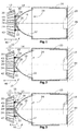
- Die Erfindung wird nachfolgend anhand eines Ausführungsbeispiels und unter Bezugnahme auf die Zeichnung näher erläutert. Im einzelnen zeigen dabei:
- Fig. 1
- einen schematisch dargestellten Mess- und Montageaufbau in derjenigen Phase, in der sich die beiden relativ zueinander zu fixierenden Komponenten der LED-Leuchte zu Beginn des Montagevorgangs befinden,
- Fig. 2
- die Situation des Montageaufbaus, in der die beiden Komponenten eine Relativposition zur Kompensation ihrer Toleranzen aufweisen, und
- Fig. 3
- der Montageaufbau bei Aushärtung einer die beiden Komponenten relativ zueinander fixierenden Klebermasse.
- In den
Fign. 1 bis 3 ist schematisch ein Montage- und Messaufbau zur automatischen Fixierung zweier Komponenten einer LED-Leuchte gezeigt, Die LED-Leuchte 10 weist dabei ein LED-Modul 12 und eine optische Einheit 14 auf. Diese beiden Komponenten der LED-Leuchte 10 sind toleranzbehaftet. Um dennoch in einem vorgeschriebenen Abstand zur LED-Leuchte eine geforderte Lichtintensität erzielen zu können, werden während des Montagevorgangs die beiden Komponenten relativ zueinander entlang der optischen Achse 16 der LED-Leuchte 10 verschoben, bis mit Hilfe eines Detektors 18 eine der gewünschten Lichtintensität entsprechende Relativposition gefunden worden ist. Der Detektor 18 befindet sich dabei innerhalb eines insbesondere teleskopierbaren Rohres 20, wobei an dem einen Ende dieses Rohres 20 der Detektor 18 und an dem gegenüberliegenden anderen Ende des Rohres 20 die optische Einheit 14 angeordnet ist. Das Rohr 20 ist vorzugsweise deshalb teleskopierbar, um mit Hilfe des Messaufbaus LED-Leuchten 10 vermessen zu können, die in unterschiedlichen Entfernungen über vorgegebene Lichtintensitäten verfügen sollen. Somit lässt sich also der Abstand des Detektors 18 zur LED-Leuchte 10 durch Teleskopierung des Rohres 20 verstellen. - Das LED-Modul 12 weist eine LED 22 mit einem Die 24 und einer transparenten Vergussmasse 26 auf. Die LED ist auf einer Platine 28 angeordnet, die ggf. Bauelemente zur Ansteuerung der LED 22 und Kontaktelemente für die elektrische Kontaktierung aufweist. Die Platine 28 befindet sich auf einem Kühlkörper 30.
- Die optische Einheit 14 weist in diesem Ausführungsbeispiel einen Reflektor 32 auf, der mit einer Lichtaustrittsöffnung 34 und einer LED-Aufnahmeöffnung 36 versehen ist. Der Reflektor 32 ist an seinem mit der Öffnung 36 versehenen Ende mit in diesem Ausführungsbeispiel drei Verbindungsstegen 38 versehen, die in Umfangsrichtung des rotationssymmetrischen Reflektors 32 gleich verteilt angeordnet sind. Den drei Verbindungsstegen 38 sind drei Aussparungen 40 in der Platine 28 zugeordnet. In diese Aussparungen wird Klebermasse 42 appliziert, in die die Enden der Verbindungsstege 38 bei der Montage der LED-Leuchte 10 eingetaucht werden.
- Wie bei 44 angedeutet, stehen das Rohr 20 und der Reflektor 32 während der Montage und Vermessung der LED-Leuchte 10 starr, sind also längs der optischen Achse 16 relativ zueinander nicht bewegbar. Demgegenüber lässt sich das LED-Modul 12 in Richtung der optischen Achse 16 vor- und zurückbewegen (siehe den Dappelpfieif 46). Alternativ könnte das LED-Modul 12 feststehend angeordnet und die Einheit aus Reflektor 32 und Rohr 20 sowie Messebene 50 mit Detektor 18 längs der optischen Achse 16 bewegbar sein. Die vorderen Enden der Verbindungsstege 38 des Reflektors 32 bilden zusammen mit den Aussparungen 40 der Platine 28 die Verbindungsstellen 48 zwischen LED-Modul 12 und optischer Einheit 14.
- Nach der Applizierung der Klebermassen 42 und Relativausrichtung von LED-Modul 12 und optischer Einheit 14, wie in
Fig. 1 gezeigt, wird die LED 22 zum Aussenden von Licht angesteuert. Dieses Licht wird innerhalb der Messebene 50 vom Detektor 18 erfasst. Anschließend wird das LED-Modul 12 verfahren, bis der Detektor 18 eine Lichtintensität erfasst, wie sie in dem vorgeschriebenen Abstand zur LED-Leuchte gefordert wird. Beim Auseinanderbewegen beider Komponenten werden die Klebermassen 42 "in die Länge" gezogen. - Es sei angenommen, dass
Fig. 2 diejenige Relativposition von LED-Modul 12 und optischer Einheit 14 zeigt, in der der Detektor 18 die gewünschte Lichtintensität misst. Wie zu erkennen ist, sind das LED-Modul 12 und die optische Einheit 14 durch die Klebermassen 42 miteinander verbunden. Anschließend erfolgt nun die Aushärtung der Klebermassen 42, was inFig. 3 bei 52 für das Beispiel einer Aushärtung der Klebermassen 42 mit Hilfe von UV-Strahlung gezeigt ist. Nach Aushärtung der Klebermassen 42 ist die Montage der beiden Komponenten der LED-Leuchte 10, nämlich des LED-Moduls 12 und der optischen Einheit 14 abgeschlossen. Danach erfolgt die weitere Herstellung der LED-Leuchte mit Lichtscheibe und ggf. einem Gehäuse, was in der Zeichnung nicht mehr dargestellt ist. - Die Erfindung wurde vorstehend anhand eines Ausführungsbeispiels erläutert, bei dem die LED-Leuchte über eine reflektive optische Einheit in Form des Reflektors 32 verfügt. Anstelle eines Reflektors kann die LED-Leuchte aber auch mit einer Linse (refraktive optische Einheit) versehen sein. Auch kann die LED-Leuchte mit einer optischen Einheit mit refraktiv und reflektiv arbeitenden optischen Elementen auf die erfindungsgemäße Weise montiert/assembliert werden.
Claims (3)
- Verfahren zur Montage einer ein LED-Modul und eine reflektive und/oder refraktive optische Einheit aufweisenden LED-Leuchte, insbesondere Lese- oder Sitzplatzleuchte für ein Fahrzeug, wie beispielsweise ein Flugzeug oder einen Reisebus, mit den folgenden Schritten:- Bereitstellen eines LED-Moduls (12), das mindestens eine LED (22) aufweist,- Bereitstellen einer reflektiven und/oder refraktiven optischen Einheit (14) zur Ausleuchtung in einer Messebene durch elektromagnetische Strahlung des LED-Moduls (12) und die optische Einheit,- Anordnen der optischen Einheit (14) und des LED-Moduls (12) zwecks späterer Fixierung aneinander,- Ansteuern des LED-Moduls (12) zur Aussendung von elektromagnetischer Strahlung zwecks Ausleuchtung in der Messebene,- Erfassen zumindest eines Teils der auf die Messebene auftreffenden elektromagnetischen Strahlung des LED-Moduls (12) durch einen Detektor (18),- Bewegen des LED-Moduls (12) relativ zur optischen Einheit (14) und/ oder der optischen Einheit (14) relativ zum LED-Modul (12) entlang der optischen Achse (16), bis der Detektor (18) elektromagnetische Strahlung des LED-Moduls (12) mit einer vorgebbaren Intensität erfasst, und- Fixieren der optischen Einheit (14) und des LED-Moduls (12) relativ zueinander in ihren aktuellen Relativpositionen.
- Verfahren nach Anspruch 1, dadurch gekennzeichnet, dass bei der Anordnung von LED-Modul (12) und optischer Einheit (14) zwecks späterer Fixierung aneinander aushärtbare Klebermasse (42) auf mechanische Kontaktstellen (46) zwischen dem LED-Modul (12) und der optischen Einheit (14) appliziert wird und dass das LED-Modul (12) und die optische Einheit (14) durch die Klebermasse (42) verbunden bleiben, wenn sie längs der optischen Achse (16) relativ zueinander bewegt werden.
- Verfahren nach Anspruch 2, dadurch gekennzeichnet, dass die Klebermasse (42) mittels UV-Strahlung (50) aushärtbar ist und dass die Fixierung von LED-Modul (12) und optischer Einheit (14) durch UV-Bestrahlung der sich zwischen ihnen erstreckenden Klebermasse (42) erfolgt.
Priority Applications (2)
| Application Number | Priority Date | Filing Date | Title |
|---|---|---|---|
| EP08101709.7A EP1995513B1 (de) | 2007-05-22 | 2008-02-18 | Verfahren zur Montage einer LED-Leuchte |
| US12/125,645 US8006376B2 (en) | 2007-05-22 | 2008-05-22 | Method for assembly of an LED light |
Applications Claiming Priority (2)
| Application Number | Priority Date | Filing Date | Title |
|---|---|---|---|
| EP07108613 | 2007-05-22 | ||
| EP08101709.7A EP1995513B1 (de) | 2007-05-22 | 2008-02-18 | Verfahren zur Montage einer LED-Leuchte |
Publications (2)
| Publication Number | Publication Date |
|---|---|
| EP1995513A1 true EP1995513A1 (de) | 2008-11-26 |
| EP1995513B1 EP1995513B1 (de) | 2015-10-21 |
Family
ID=38561747
Family Applications (1)
| Application Number | Title | Priority Date | Filing Date |
|---|---|---|---|
| EP08101709.7A Active EP1995513B1 (de) | 2007-05-22 | 2008-02-18 | Verfahren zur Montage einer LED-Leuchte |
Country Status (2)
| Country | Link |
|---|---|
| US (1) | US8006376B2 (de) |
| EP (1) | EP1995513B1 (de) |
Cited By (2)
| Publication number | Priority date | Publication date | Assignee | Title |
|---|---|---|---|---|
| EP2927567A4 (de) * | 2012-11-29 | 2016-07-20 | Toshiba Lighting & Technology | Lichtemittierende vorrichtung beleuchtungsvorrichtung für ein fahrzeug |
| CN106704944A (zh) * | 2015-05-20 | 2017-05-24 | 古德里奇照明系统有限责任公司 | 动态飞机外部灯单元以及操作动态飞机外部灯单元的方法 |
Families Citing this family (3)
| Publication number | Priority date | Publication date | Assignee | Title |
|---|---|---|---|---|
| US7874055B2 (en) * | 2005-03-04 | 2011-01-25 | Musco Corporation | Method and system for assembly of lighting fixtures |
| JP2014011045A (ja) * | 2012-06-29 | 2014-01-20 | Toshiba Lighting & Technology Corp | 照明装置及び照明システム |
| US20160366395A1 (en) * | 2015-06-12 | 2016-12-15 | Microsoft Technology Licensing, Llc | Led surface emitting structured light |
Citations (6)
| Publication number | Priority date | Publication date | Assignee | Title |
|---|---|---|---|---|
| US4237474A (en) | 1978-10-18 | 1980-12-02 | Rca Corporation | Electroluminescent diode and optical fiber assembly |
| US4500165A (en) | 1982-04-02 | 1985-02-19 | Codenoll Technology Corporation | Method and apparatus for aligning optical fibers |
| EP0420214A2 (de) * | 1989-09-27 | 1991-04-03 | Toshiba Lighting & Technology Corporation | Leuchtvorrichtung und Verfahren zum Verkleben eines Spiegelreflektors mit einer Lampe |
| EP0481877A1 (de) * | 1990-10-19 | 1992-04-22 | Thomson-Csf Semiconducteurs Specifiques | Ausrichtvorrichtung von einer optischen Faser und von einem optoelektronischen Bauelement |
| FR2767928A1 (fr) | 1997-09-01 | 1999-03-05 | Alliance Tech Ind | Dispositif de couplage d'une fibre optique a une source, et procede de fixation d'une embase d'un tel dispositif |
| WO2001002775A1 (en) * | 1999-07-01 | 2001-01-11 | Jari Ruuttu | Lamp structure |
Family Cites Families (1)
| Publication number | Priority date | Publication date | Assignee | Title |
|---|---|---|---|---|
| US20080074884A1 (en) * | 2006-09-25 | 2008-03-27 | Thye Linn Mok | Compact high-intensty LED-based light source and method for making the same |
-
2008
- 2008-02-18 EP EP08101709.7A patent/EP1995513B1/de active Active
- 2008-05-22 US US12/125,645 patent/US8006376B2/en active Active
Patent Citations (7)
| Publication number | Priority date | Publication date | Assignee | Title |
|---|---|---|---|---|
| US4237474A (en) | 1978-10-18 | 1980-12-02 | Rca Corporation | Electroluminescent diode and optical fiber assembly |
| US4500165A (en) | 1982-04-02 | 1985-02-19 | Codenoll Technology Corporation | Method and apparatus for aligning optical fibers |
| EP0420214A2 (de) * | 1989-09-27 | 1991-04-03 | Toshiba Lighting & Technology Corporation | Leuchtvorrichtung und Verfahren zum Verkleben eines Spiegelreflektors mit einer Lampe |
| EP0481877A1 (de) * | 1990-10-19 | 1992-04-22 | Thomson-Csf Semiconducteurs Specifiques | Ausrichtvorrichtung von einer optischen Faser und von einem optoelektronischen Bauelement |
| US5177807A (en) | 1990-10-19 | 1993-01-05 | Thomson Hybrides | Device for the alignment of an optical fiber and an optoelectronic component |
| FR2767928A1 (fr) | 1997-09-01 | 1999-03-05 | Alliance Tech Ind | Dispositif de couplage d'une fibre optique a une source, et procede de fixation d'une embase d'un tel dispositif |
| WO2001002775A1 (en) * | 1999-07-01 | 2001-01-11 | Jari Ruuttu | Lamp structure |
Cited By (3)
| Publication number | Priority date | Publication date | Assignee | Title |
|---|---|---|---|---|
| EP2927567A4 (de) * | 2012-11-29 | 2016-07-20 | Toshiba Lighting & Technology | Lichtemittierende vorrichtung beleuchtungsvorrichtung für ein fahrzeug |
| US9618188B2 (en) | 2012-11-29 | 2017-04-11 | Toshiba Lighting & Technology Corporation | Light emitting device and vehicular lighting device |
| CN106704944A (zh) * | 2015-05-20 | 2017-05-24 | 古德里奇照明系统有限责任公司 | 动态飞机外部灯单元以及操作动态飞机外部灯单元的方法 |
Also Published As
| Publication number | Publication date |
|---|---|
| US20090025202A1 (en) | 2009-01-29 |
| US8006376B2 (en) | 2011-08-30 |
| EP1995513B1 (de) | 2015-10-21 |
Similar Documents
| Publication | Publication Date | Title |
|---|---|---|
| DE102012213844B4 (de) | Lichtmodul für KFZ-Scheinwerfer mit zwei Optikeinheiten und zugehörigen Befestigungseinrichtungen | |
| EP3339720B1 (de) | Primäroptikbaugruppe zum einsatz in einer kraftfahrzeugbeleuchtungseinrichtung und kraftfahrzeugbeleuchtungseinrichtung mit einer solchen primäroptikbaugruppe | |
| DE102009022723A1 (de) | Von rückwärts anzubringendes Leuchtdioden-Modul für Kombinationsrücklichter an Kraftfahrzeugen | |
| EP1995513B1 (de) | Verfahren zur Montage einer LED-Leuchte | |
| DE102010063713A1 (de) | Beleuchtungsvorrichtung | |
| EP3321570B1 (de) | Verfahren zur anordnung eines schaltungsträgers und beleuchtungseinrichtung für ein kraftfahrzeug mit einem nach diesem verfahren angeordneten schaltungsträger | |
| DE102011015161A1 (de) | LED-Beleuchtungseinrichtung | |
| DE102012213841A1 (de) | Lichtmodul | |
| DE10131686A1 (de) | Taschenlampe | |
| DE102006039705A1 (de) | Linsenvorsatz für einen Scheinwerfer | |
| DE10341884B4 (de) | Flexible Schaltungsträgeranordnung | |
| DE102010054922B4 (de) | Scheinwerfer für ein Fahrzeug mit einer Halbleiterlichtquelle | |
| AT516638A1 (de) | Verfahren zur Herstellung eines Schaltungsträgers und Schaltungsträger | |
| DE202017001946U1 (de) | Scheinwerfer mit einem optischen System mit statischem Matrix-Abbiegelicht | |
| DE102009023645A1 (de) | LED-Modul | |
| EP3088798B1 (de) | Verfahren und vorrichtung zur anordnung eines schaltungsträgers mit einer halbleiterlichtquelle in einer bestimmten lage relativ zu einem optischen system einer beleuchtungseinrichtung | |
| EP3671014B1 (de) | Led-scheinwerfermodul und led-lichtmodul zur verwendung in einem solchen led-scheinwerfermodul | |
| EP1925876B1 (de) | LED-Lichtquellensystem | |
| DE102009054101A1 (de) | Beleuchtungsvorrichtung für ein Fahrzeug | |
| EP3452753B1 (de) | Vorrichtung zur anordnung eines schaltungsträgers | |
| DE102016105730A1 (de) | Verfahren und Gerät zum Reduzieren von Rändern des Lichtbilds eines Scheinwerfers und Scheinwerfer | |
| WO2012150121A1 (de) | Strahlungsemittierende vorrichtung und verwendung einer derartigen vorrichtung | |
| EP2664496B1 (de) | Verfahren zur Herstellung von Kraftfahrzeugleuchten | |
| DE102011084062A1 (de) | LED-Beleuchtungseinrichtung | |
| DE102009051026B4 (de) | LED-Beleuchtungsvorrichtung umfassend wenigstens eine LED und eine Platine, auf der die LED angeordnet ist, und Kraftfahrzeug |
Legal Events
| Date | Code | Title | Description |
|---|---|---|---|
| PUAI | Public reference made under article 153(3) epc to a published international application that has entered the european phase |
Free format text: ORIGINAL CODE: 0009012 |
|
| AK | Designated contracting states |
Kind code of ref document: A1 Designated state(s): AT BE BG CH CY CZ DE DK EE ES FI FR GB GR HR HU IE IS IT LI LT LU LV MC MT NL NO PL PT RO SE SI SK TR |
|
| AX | Request for extension of the european patent |
Extension state: AL BA MK RS |
|
| 17P | Request for examination filed |
Effective date: 20090421 |
|
| 17Q | First examination report despatched |
Effective date: 20090615 |
|
| AKX | Designation fees paid |
Designated state(s): AT BE BG CH CY CZ DE DK EE ES FI FR GB GR HR HU IE IS IT LI LT LU LV MC MT NL NO PL PT RO SE SI SK TR |
|
| GRAP | Despatch of communication of intention to grant a patent |
Free format text: ORIGINAL CODE: EPIDOSNIGR1 |
|
| INTG | Intention to grant announced |
Effective date: 20150326 |
|
| GRAS | Grant fee paid |
Free format text: ORIGINAL CODE: EPIDOSNIGR3 |
|
| GRAA | (expected) grant |
Free format text: ORIGINAL CODE: 0009210 |
|
| AK | Designated contracting states |
Kind code of ref document: B1 Designated state(s): AT BE BG CH CY CZ DE DK EE ES FI FR GB GR HR HU IE IS IT LI LT LU LV MC MT NL NO PL PT RO SE SI SK TR |
|
| REG | Reference to a national code |
Ref country code: GB Ref legal event code: FG4D Free format text: NOT ENGLISH Ref country code: NL Ref legal event code: MP Effective date: 20151021 |
|
| REG | Reference to a national code |
Ref country code: CH Ref legal event code: EP |
|
| REG | Reference to a national code |
Ref country code: AT Ref legal event code: REF Ref document number: 756846 Country of ref document: AT Kind code of ref document: T Effective date: 20151115 |
|
| REG | Reference to a national code |
Ref country code: IE Ref legal event code: FG4D Free format text: LANGUAGE OF EP DOCUMENT: GERMAN |
|
| REG | Reference to a national code |
Ref country code: DE Ref legal event code: R096 Ref document number: 502008013496 Country of ref document: DE |
|
| REG | Reference to a national code |
Ref country code: FR Ref legal event code: PLFP Year of fee payment: 9 |
|
| REG | Reference to a national code |
Ref country code: LT Ref legal event code: MG4D |
|
| PG25 | Lapsed in a contracting state [announced via postgrant information from national office to epo] |
Ref country code: NL Free format text: LAPSE BECAUSE OF FAILURE TO SUBMIT A TRANSLATION OF THE DESCRIPTION OR TO PAY THE FEE WITHIN THE PRESCRIBED TIME-LIMIT Effective date: 20151021 Ref country code: IT Free format text: LAPSE BECAUSE OF FAILURE TO SUBMIT A TRANSLATION OF THE DESCRIPTION OR TO PAY THE FEE WITHIN THE PRESCRIBED TIME-LIMIT Effective date: 20151021 Ref country code: NO Free format text: LAPSE BECAUSE OF FAILURE TO SUBMIT A TRANSLATION OF THE DESCRIPTION OR TO PAY THE FEE WITHIN THE PRESCRIBED TIME-LIMIT Effective date: 20160121 Ref country code: ES Free format text: LAPSE BECAUSE OF FAILURE TO SUBMIT A TRANSLATION OF THE DESCRIPTION OR TO PAY THE FEE WITHIN THE PRESCRIBED TIME-LIMIT Effective date: 20151021 Ref country code: IS Free format text: LAPSE BECAUSE OF FAILURE TO SUBMIT A TRANSLATION OF THE DESCRIPTION OR TO PAY THE FEE WITHIN THE PRESCRIBED TIME-LIMIT Effective date: 20160221 Ref country code: LT Free format text: LAPSE BECAUSE OF FAILURE TO SUBMIT A TRANSLATION OF THE DESCRIPTION OR TO PAY THE FEE WITHIN THE PRESCRIBED TIME-LIMIT Effective date: 20151021 Ref country code: HR Free format text: LAPSE BECAUSE OF FAILURE TO SUBMIT A TRANSLATION OF THE DESCRIPTION OR TO PAY THE FEE WITHIN THE PRESCRIBED TIME-LIMIT Effective date: 20151021 |
|
| PG25 | Lapsed in a contracting state [announced via postgrant information from national office to epo] |
Ref country code: LV Free format text: LAPSE BECAUSE OF FAILURE TO SUBMIT A TRANSLATION OF THE DESCRIPTION OR TO PAY THE FEE WITHIN THE PRESCRIBED TIME-LIMIT Effective date: 20151021 Ref country code: PL Free format text: LAPSE BECAUSE OF FAILURE TO SUBMIT A TRANSLATION OF THE DESCRIPTION OR TO PAY THE FEE WITHIN THE PRESCRIBED TIME-LIMIT Effective date: 20151021 Ref country code: PT Free format text: LAPSE BECAUSE OF FAILURE TO SUBMIT A TRANSLATION OF THE DESCRIPTION OR TO PAY THE FEE WITHIN THE PRESCRIBED TIME-LIMIT Effective date: 20160222 Ref country code: SE Free format text: LAPSE BECAUSE OF FAILURE TO SUBMIT A TRANSLATION OF THE DESCRIPTION OR TO PAY THE FEE WITHIN THE PRESCRIBED TIME-LIMIT Effective date: 20151021 Ref country code: FI Free format text: LAPSE BECAUSE OF FAILURE TO SUBMIT A TRANSLATION OF THE DESCRIPTION OR TO PAY THE FEE WITHIN THE PRESCRIBED TIME-LIMIT Effective date: 20151021 Ref country code: GR Free format text: LAPSE BECAUSE OF FAILURE TO SUBMIT A TRANSLATION OF THE DESCRIPTION OR TO PAY THE FEE WITHIN THE PRESCRIBED TIME-LIMIT Effective date: 20160122 Ref country code: BE Free format text: LAPSE BECAUSE OF NON-PAYMENT OF DUE FEES Effective date: 20160229 |
|
| REG | Reference to a national code |
Ref country code: DE Ref legal event code: R097 Ref document number: 502008013496 Country of ref document: DE |
|
| PG25 | Lapsed in a contracting state [announced via postgrant information from national office to epo] |
Ref country code: CZ Free format text: LAPSE BECAUSE OF FAILURE TO SUBMIT A TRANSLATION OF THE DESCRIPTION OR TO PAY THE FEE WITHIN THE PRESCRIBED TIME-LIMIT Effective date: 20151021 |
|
| PLBE | No opposition filed within time limit |
Free format text: ORIGINAL CODE: 0009261 |
|
| STAA | Information on the status of an ep patent application or granted ep patent |
Free format text: STATUS: NO OPPOSITION FILED WITHIN TIME LIMIT |
|
| PG25 | Lapsed in a contracting state [announced via postgrant information from national office to epo] |
Ref country code: RO Free format text: LAPSE BECAUSE OF FAILURE TO SUBMIT A TRANSLATION OF THE DESCRIPTION OR TO PAY THE FEE WITHIN THE PRESCRIBED TIME-LIMIT Effective date: 20151021 Ref country code: DK Free format text: LAPSE BECAUSE OF FAILURE TO SUBMIT A TRANSLATION OF THE DESCRIPTION OR TO PAY THE FEE WITHIN THE PRESCRIBED TIME-LIMIT Effective date: 20151021 Ref country code: SK Free format text: LAPSE BECAUSE OF FAILURE TO SUBMIT A TRANSLATION OF THE DESCRIPTION OR TO PAY THE FEE WITHIN THE PRESCRIBED TIME-LIMIT Effective date: 20151021 Ref country code: EE Free format text: LAPSE BECAUSE OF FAILURE TO SUBMIT A TRANSLATION OF THE DESCRIPTION OR TO PAY THE FEE WITHIN THE PRESCRIBED TIME-LIMIT Effective date: 20151021 |
|
| 26N | No opposition filed |
Effective date: 20160722 |
|
| PG25 | Lapsed in a contracting state [announced via postgrant information from national office to epo] |
Ref country code: LU Free format text: LAPSE BECAUSE OF FAILURE TO SUBMIT A TRANSLATION OF THE DESCRIPTION OR TO PAY THE FEE WITHIN THE PRESCRIBED TIME-LIMIT Effective date: 20160218 Ref country code: MC Free format text: LAPSE BECAUSE OF FAILURE TO SUBMIT A TRANSLATION OF THE DESCRIPTION OR TO PAY THE FEE WITHIN THE PRESCRIBED TIME-LIMIT Effective date: 20151021 |
|
| REG | Reference to a national code |
Ref country code: CH Ref legal event code: PL |
|
| PG25 | Lapsed in a contracting state [announced via postgrant information from national office to epo] |
Ref country code: CH Free format text: LAPSE BECAUSE OF NON-PAYMENT OF DUE FEES Effective date: 20160229 Ref country code: LI Free format text: LAPSE BECAUSE OF NON-PAYMENT OF DUE FEES Effective date: 20160229 |
|
| PG25 | Lapsed in a contracting state [announced via postgrant information from national office to epo] |
Ref country code: SI Free format text: LAPSE BECAUSE OF FAILURE TO SUBMIT A TRANSLATION OF THE DESCRIPTION OR TO PAY THE FEE WITHIN THE PRESCRIBED TIME-LIMIT Effective date: 20151021 |
|
| REG | Reference to a national code |
Ref country code: IE Ref legal event code: MM4A |
|
| REG | Reference to a national code |
Ref country code: FR Ref legal event code: PLFP Year of fee payment: 10 |
|
| PG25 | Lapsed in a contracting state [announced via postgrant information from national office to epo] |
Ref country code: IE Free format text: LAPSE BECAUSE OF NON-PAYMENT OF DUE FEES Effective date: 20160218 |
|
| REG | Reference to a national code |
Ref country code: AT Ref legal event code: MM01 Ref document number: 756846 Country of ref document: AT Kind code of ref document: T Effective date: 20160218 |
|
| PG25 | Lapsed in a contracting state [announced via postgrant information from national office to epo] |
Ref country code: AT Free format text: LAPSE BECAUSE OF NON-PAYMENT OF DUE FEES Effective date: 20160218 |
|
| REG | Reference to a national code |
Ref country code: DE Ref legal event code: R082 Ref document number: 502008013496 Country of ref document: DE Representative=s name: SCHMITT-NILSON SCHRAUD WAIBEL WOHLFROM PATENTA, DE |
|
| PG25 | Lapsed in a contracting state [announced via postgrant information from national office to epo] |
Ref country code: MT Free format text: LAPSE BECAUSE OF FAILURE TO SUBMIT A TRANSLATION OF THE DESCRIPTION OR TO PAY THE FEE WITHIN THE PRESCRIBED TIME-LIMIT Effective date: 20151021 |
|
| REG | Reference to a national code |
Ref country code: FR Ref legal event code: PLFP Year of fee payment: 11 |
|
| PG25 | Lapsed in a contracting state [announced via postgrant information from national office to epo] |
Ref country code: HU Free format text: LAPSE BECAUSE OF FAILURE TO SUBMIT A TRANSLATION OF THE DESCRIPTION OR TO PAY THE FEE WITHIN THE PRESCRIBED TIME-LIMIT; INVALID AB INITIO Effective date: 20080218 Ref country code: CY Free format text: LAPSE BECAUSE OF FAILURE TO SUBMIT A TRANSLATION OF THE DESCRIPTION OR TO PAY THE FEE WITHIN THE PRESCRIBED TIME-LIMIT Effective date: 20151021 |
|
| PG25 | Lapsed in a contracting state [announced via postgrant information from national office to epo] |
Ref country code: TR Free format text: LAPSE BECAUSE OF FAILURE TO SUBMIT A TRANSLATION OF THE DESCRIPTION OR TO PAY THE FEE WITHIN THE PRESCRIBED TIME-LIMIT Effective date: 20151021 |
|
| PG25 | Lapsed in a contracting state [announced via postgrant information from national office to epo] |
Ref country code: BG Free format text: LAPSE BECAUSE OF FAILURE TO SUBMIT A TRANSLATION OF THE DESCRIPTION OR TO PAY THE FEE WITHIN THE PRESCRIBED TIME-LIMIT Effective date: 20151021 |
|
| RIC2 | Information provided on ipc code assigned after grant |
Ipc: G02B 27/62 20060101ALI20080710BHEP Ipc: F21Y 101/02 20000101ALN20080710BHEP Ipc: G02B 7/182 20060101ALI20080710BHEP Ipc: F21V 17/10 20060101AFI20080710BHEP Ipc: G02B 7/00 20060101ALI20080710BHEP |
|
| P01 | Opt-out of the competence of the unified patent court (upc) registered |
Effective date: 20230630 |
|
| PGFP | Annual fee paid to national office [announced via postgrant information from national office to epo] |
Ref country code: GB Payment date: 20260121 Year of fee payment: 19 |
|
| PGFP | Annual fee paid to national office [announced via postgrant information from national office to epo] |
Ref country code: DE Payment date: 20260121 Year of fee payment: 19 |
|
| PGFP | Annual fee paid to national office [announced via postgrant information from national office to epo] |
Ref country code: FR Payment date: 20260121 Year of fee payment: 19 |