EP1995173A1 - Plasma flow control actuator system and method - Google Patents
Plasma flow control actuator system and method Download PDFInfo
- Publication number
- EP1995173A1 EP1995173A1 EP08156381A EP08156381A EP1995173A1 EP 1995173 A1 EP1995173 A1 EP 1995173A1 EP 08156381 A EP08156381 A EP 08156381A EP 08156381 A EP08156381 A EP 08156381A EP 1995173 A1 EP1995173 A1 EP 1995173A1
- Authority
- EP
- European Patent Office
- Prior art keywords
- electrodes
- boundary layer
- plasma actuator
- voltage
- layer flow
- Prior art date
- Legal status (The legal status is an assumption and is not a legal conclusion. Google has not performed a legal analysis and makes no representation as to the accuracy of the status listed.)
- Granted
Links
Images
Classifications
-
- B—PERFORMING OPERATIONS; TRANSPORTING
- B64—AIRCRAFT; AVIATION; COSMONAUTICS
- B64C—AEROPLANES; HELICOPTERS
- B64C23/00—Influencing air flow over aircraft surfaces, not otherwise provided for
- B64C23/005—Influencing air flow over aircraft surfaces, not otherwise provided for by other means not covered by groups B64C23/02 - B64C23/08, e.g. by electric charges, magnetic panels, piezoelectric elements, static charges or ultrasounds
-
- F—MECHANICAL ENGINEERING; LIGHTING; HEATING; WEAPONS; BLASTING
- F15—FLUID-PRESSURE ACTUATORS; HYDRAULICS OR PNEUMATICS IN GENERAL
- F15D—FLUID DYNAMICS, i.e. METHODS OR MEANS FOR INFLUENCING THE FLOW OF GASES OR LIQUIDS
- F15D1/00—Influencing flow of fluids
- F15D1/10—Influencing flow of fluids around bodies of solid material
- F15D1/12—Influencing flow of fluids around bodies of solid material by influencing the boundary layer
-
- H—ELECTRICITY
- H05—ELECTRIC TECHNIQUES NOT OTHERWISE PROVIDED FOR
- H05H—PLASMA TECHNIQUE; PRODUCTION OF ACCELERATED ELECTRICALLY-CHARGED PARTICLES OR OF NEUTRONS; PRODUCTION OR ACCELERATION OF NEUTRAL MOLECULAR OR ATOMIC BEAMS
- H05H1/00—Generating plasma; Handling plasma
- H05H1/54—Plasma accelerators
-
- B—PERFORMING OPERATIONS; TRANSPORTING
- B64—AIRCRAFT; AVIATION; COSMONAUTICS
- B64C—AEROPLANES; HELICOPTERS
- B64C2230/00—Boundary layer controls
- B64C2230/12—Boundary layer controls by using electromagnetic tiles, fluid ionizers, static charges or plasma
-
- Y—GENERAL TAGGING OF NEW TECHNOLOGICAL DEVELOPMENTS; GENERAL TAGGING OF CROSS-SECTIONAL TECHNOLOGIES SPANNING OVER SEVERAL SECTIONS OF THE IPC; TECHNICAL SUBJECTS COVERED BY FORMER USPC CROSS-REFERENCE ART COLLECTIONS [XRACs] AND DIGESTS
- Y02—TECHNOLOGIES OR APPLICATIONS FOR MITIGATION OR ADAPTATION AGAINST CLIMATE CHANGE
- Y02T—CLIMATE CHANGE MITIGATION TECHNOLOGIES RELATED TO TRANSPORTATION
- Y02T50/00—Aeronautics or air transport
- Y02T50/10—Drag reduction
Definitions
- the present disclosure relates to flow control systems, and more particularly to a plasma flow control system and method that is selectively controllable to help prevent separation of a boundary layer flow from a surface of a mobile platform or object, or to cause separation of the boundary layer flow from the surface.
- airborne mobile platforms such as aircraft and weapons (air vehicles) typically must have highly integrated configurations. These configurations typically need to combine good performance and useful payload with good stability and control characteristics.
- air vehicle configurations should have efficient, effective and robust control effector suites. Removing conventional control surfaces to make the air vehicle aerodynamically more efficient provides a unique challenge in air vehicle stability and control.
- Weight is also an important consideration on many forms of mobile platforms, and particularly airborne mobile platforms such as aircraft.
- Present day aerodynamic control systems typically employ hinged panels that are deflected to alter the boundary layer flow over a surface of the mobile platform, such as over a trailing edge of a wing.
- hinges and the related linkage and hydraulic or electromechanical actuators needed to employ them can add significant weight to an aircraft, thereby increasing the fuel required for a given flight or mission, or reducing the overall payload of the aircraft.
- the present disclosure relates to a plasma actuator system and method for use on mobile platforms, and particularly on high speed airborne mobile platforms such as jet aircraft.
- the plasma actuator system forms a flow control apparatus that is useful for controlling a boundary layer flow over a surface of the mobile platform.
- a method for controlling flight of a mobile platform. The method involves disposing a plasma actuator on a surface of the mobile platform so as to be in a path of a boundary layer flow over the surface.
- the plasma actuator is controlled to assume a first operating configuration in which the plasma actuator influences the boundary layer flow in a manner to draw the boundary layer toward the surface and maintain the boundary layer flow against the surface.
- the actuator may also be controlled to assume a second operating configuration in which the plasma actuator influences the boundary layer flow in a manner to cause separation of the boundary layer flow from the surface.
- disposing the plasma actuator involves disposing a plasma actuator having first and third electrodes spaced apart along a direction of flow of the boundary layer.
- a third electrode is disposed intermediate the first and second electrodes, and within a plane that is laterally offset from a plane in which the first and second electrodes are disposed.
- a dielectric material is disposed between the third electrode and the first and second electrodes.
- a system for controlling flight of an airborne mobile platform includes a plasma actuator disposed adjacent a surface of a mobile platform and an AC voltage source for electrically energizing the plasma actuator.
- the plasma actuator has a first electrode disposed adjacent the surface of the mobile platform so as to be in a path of a boundary layer flow over the surface, and a second electrode disposed adjacent the surface downstream of the first electrode, relative to a direction of flow of the boundary layer.
- a third electrode is separated from the first and second electrodes by a dielectric layer, and is disposed between the first and second electrodes and within a plane that is laterally offset from the first and second electrodes.
- a controller controls the application of an AC voltage from the AC voltage source to the electrodes to at least one of:
- the system and method forms a plasma actuator that is able to selectively prevent separation of a boundary layer flow from a surface of an object, as well as to cause separation of the boundary layer flow.
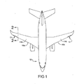
- Figure 1 is a plan view of a mobile platform incorporating a plurality of plasma actuators in accordance with one embodiment of the present disclosure, where the plasma actuators are employed along the leading edges of the wings of an aircraft;
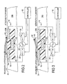
- Figure 2 is an enlarged cross-sectional side view of one of the plasma actuators shown in Figure 1 taken in accordance with section line 2-2 in Figure 1 , illustrating the actuator energized to delay separation of the boundary layer flow on the surface of the wing, and also showing in simplified form the AC voltage source and the controller used to control the actuator; and
- Figure 3 is view of the plasma actuator of Figure 2 , but with the actuator being controlled to cause separation of the boundary layer flow from the surface of the wing.
- a mobile platform in this example an aircraft 12, incorporating a plurality of plasma actuators 10.
- the plasma actuators 10 are disposed adjacent leading edges 16a and 16b of the wings 14a and 14b, respectively, of the aircraft 12. It will be appreciated, however, that the plasma actuators 10 may be used on virtually any form of mobile platform where it is desirable to effect directional or attitude control of the mobile platform without the need for hinged or moveable panels. Other possible applications may involve unmanned aircraft, missiles, rotorcraft, high speed land vehicles, and possibly even high speed marine vessels.
- plasma actuators 10 are illustrated on the wings 14a,14b of the aircraft 12, they could just as readily be employed along the fuselage, on the horizontal stabilizers, the vertical tail, boattail or any other location where it may be desirable to influence the boundary layer flow over the aircraft.
- Each plasma actuator 10 includes a first electrode 18, a second electrode 20 and a third electrode 22.
- the second electrode 20 is spaced apart from the first electrode 18.
- the electrodes 18 and 20 are recessed mounted in a surface 24 of the wing 14a so that upper surfaces 18a and 20a of the electrodes 18 and 20, respectively, are positioned generally flush with the surface 24, and co-planar with one another.
- the electrodes 18 and 20 could be mounted on top of the surface 24. Recess mounting of the electrodes 18 and 20, however, will help to maintain the original aerodynamic profile of the wing 14a or other surface with which the actuator 10 is being implemented on and to reduce aerodynamic drag.
- the third electrode 22 is mounted between the first electrode 18 and the second electrode 20, and generally longitudinally in line with the electrodes 18 and 20, but is disposed so that it sits laterally offset from (i.e., elevationally below) the electrodes 18 and 20.
- a dielectric layer of material 25 is provided around the third electrode 22 that separates it from the first and second electrodes 18 and 20, respectively.
- Each of the electrodes 18, 20 and 22 may be formed with a generally rectangular shape having its major (i.e., long side) axis arranged perpendicular to the direction of flow of the boundary layer. Other orientations are possible as well, depending on the needs of a specific application.
- the electrodes 18,20,22 may be formed from any conductive material. Copper is one material that is particularly suitable.
- the electrodes 18,20,22 may be formed as thin strips, possibly as foil strips, and may have a typical thickness on the order of about 0.001-0.005inch (.0254-0.127mm).
- the length and width of each electrode 18,20,22 may vary as needed to suit specific applications, but it is anticipated that in many aircraft applications, the length and width of each electrode may typically be on the order of 1-20 inches (2.54cm-50.08cm) for the length and 0.12-0.20inch (3-5mm) for the width for each of the electrodes 18 and 20.
- the width of the buried electrode 22 will typically be wider than that employed for the electrode 22, and typically on the order of 1.0-2.0 inches (2.54cm-5.08cm) depending on the operating voltage being supplied by the AC voltage source 26.
- the dielectric layer of material 25 may comprise any suitable dielectric material, for example quartz, KAPTON® or TEFLON® dielectric materials. Other dielectric materials such as ceramics may also be suitable for use, and the precise dielectric used may be dictated by the needs of a specific application. A portion of the dielectric layer of material 25 may also be used to fill the gap between the first and second electrodes 18 and 20.
- the elevational spacing of the third electrode 22 from the first and second electrodes 18 and 20, will typically be about 0.003-0.50 inch (0.076-12.7mm), although this may also vary significantly as well depending on the needs of a specific application.
- an AC voltage source 26 is coupled to the third electrode 22 and through a pair of switches 28 and 30 to the first and second electrodes 18 and 22, respectively.
- the AC voltage source 26 generates a low current, high voltage AC signal, preferably in the range of about 3,000-20,000 volts.
- the frequency of the AC voltage source 26 is typically between about 1KHz-20KHz, but may vary as needed to meet a specific application.
- the precise output from the AC voltage source 26 is preferably variable to enable the actuator 10 to provide a variable degree of fluid flow control.
- a controller 32 is in communication with the switches 28 and 30.
- the switches 28,30 may be semiconductor switching devices suitable for handling the voltage generated by the AC voltage source 26 or may comprise any other suitable forms of switching devices.
- components 18, 20, 22, 25, 26, 28, 30 and 32 effectively form a "dual mode" plasma actuator apparatus that is able to selectively cause or inhibit separation of the boundary layer from the surface 24.
- the controller 32 may also be used to control the precise output from the AC voltage source 26.
- the controller 32 may be used to control the switches 28 and 30 to generate AC voltage pulses that are applied across the electrode pairs 18,22 and 20,22, with a duty cycle between about 10%-100%. Applying a pulsed AC signal to the electrode pairs 18,22 and 20,22 may result in an increase in power efficiency and overall effectiveness of the actuator 10.
- the controller 32 when it is desired to prevent separation of the boundary layer flow from the surface 24, the controller 32 causes switch 28 to be energized (i.e., closed) and switch 30 to be opened. This results in the high AC voltage from the AC voltage source 26 being applied across electrodes 18 and 22. The high voltage causes air in the vicinity of the spacing between electrodes 18 and 22 to be ionized. Ionization typically occurs when an AC voltage of about 3,000 volts is applied across the electrodes 18 and 22. The electric field that is created acts on the ionized air to accelerate the charged particles, which collide with the neutral boundary layer air molecules to create a "wall jet".
- the strength of the electric field is directly proportional to the magnitude of the applied AC voltage. More particularly, the electric field induces a body force impulse on the ionized air that serves to induce a fluid flow (i.e., the wall jet) very near the surface 24.
- the induced fluid flow is indicated by arrow 34.
- the induced fluid flow 34 causes an increase in the momentum of the boundary layer fluid near the surface 24.
- the resulting induced fluid flow is from the first electrode 18 toward the third electrode 22.
- the induced fluid flow 34 functions to prevent, or at least significantly delay, separation of the boundary layer from the surface 24. Accordingly, Figure 2 illustrates what may be viewed as an "attached flow mode" or "first operating configuration" for the actuator 10.
- the controller 32 energizes (i.e., closes) switch 30 and opens switch 28. This also causes the air in the region between the second electrode 20 and the third electrode 22 to ionize, but the induced fluid flow, represented by arrow 36, is in a direction generally opposite to the induced fluid flow 34.
- the induced fluid flow 36 serves to cause separation of the boundary layer from the surface 24.
- the plasma actuators 10 may be used for directional control purposes, for instance at low angle of attack, by controlling the actuators 10 on the wings 14a and 14b differently. For example, by controlling the plasma actuators 10 on wing 14a so that one effect is achieved, for example preventing flow separation, while controlling the actuators 10 on wing 14b to induce flow separation, directional control of the aircraft 12 can be achieved.
- the directional control results from the differential drag produced by the cooperative effects of the plasma actuators 10 on the wings 14a and 14b, and the moment arm generated at each wingtip about the centerline of each wing 14a and 14b.
- the plasma actuators 10 may be implemented on the aircraft 12.
- the plasma actuators 10 may instead be used to generate a differential side force on the fuselage of an aircraft or missile, and thus generate a yawing moment.
- a differential lift could be generated at the wings 14a and 14b to induce a roll moment.
- the elimination or reduction of conventional mechanical/hydraulic drive control effectors can significantly reduce the weight of an aircraft, and thus produce increased mission flight time or range for a given aircraft.
- the plasma actuators 10 and related system and methodology described herein may be used to replace conventional control effectors such as leading or trailing edge flaps, ailerons, moving tail surfaces and vortex generators, thus reducing weight and drag associated with such components.
Landscapes
- Engineering & Computer Science (AREA)
- Physics & Mathematics (AREA)
- Plasma & Fusion (AREA)
- Spectroscopy & Molecular Physics (AREA)
- Aviation & Aerospace Engineering (AREA)
- Fluid Mechanics (AREA)
- Mechanical Engineering (AREA)
- General Engineering & Computer Science (AREA)
- Plasma Technology (AREA)
- Paper (AREA)
- Control Of Position, Course, Altitude, Or Attitude Of Moving Bodies (AREA)
- Traffic Control Systems (AREA)
Abstract
Description
- The present application is related in general subject matter to
U.S. application serial number 11/753,857 (Boeing docket 07-0456; HDP Docket 7784-001059) andU.S. application serial number 11/753,869 (Boeing Docket 07-0455; HDP Docket 7784-001060), both filed concurrently herewith on May 25,2007. - The present disclosure is also related in general subject matter to
U.S. Application Serial Number serial number 11/403,252 , filed 4/12/06, and assigned to The Boeing Company. - All of the above-mentioned applications are hereby incorporated by reference into the present disclosure.
- The present disclosure relates to flow control systems, and more particularly to a plasma flow control system and method that is selectively controllable to help prevent separation of a boundary layer flow from a surface of a mobile platform or object, or to cause separation of the boundary layer flow from the surface.
- The statements in this section merely provide background information related to the present disclosure and may not constitute prior art.
- To be aerodynamically efficient, airborne mobile platforms such as aircraft and weapons (air vehicles) typically must have highly integrated configurations. These configurations typically need to combine good performance and useful payload with good stability and control characteristics. To achieve this objective, air vehicle configurations should have efficient, effective and robust control effector suites. Removing conventional control surfaces to make the air vehicle aerodynamically more efficient provides a unique challenge in air vehicle stability and control.
- Previous work with air vehicles that are tailless and/or hingeless has proven especially challenging in providing vehicle control, especially directional control of the vehicle. A particular problem with hingeless or tailless control is generating directional control at low to moderate angles of attack, with such angles typically being in the range between about 0-4 degrees. At the present time, most aerodynamic methods used for generating directional control at low to moderate angles of attack on an air vehicle involve the use of vertical tails or deflecting a control surface. Providing directional control at low to moderate angles of attack, if any, is a limitation of prior solutions when the vertical tail is removed.
- Weight is also an important consideration on many forms of mobile platforms, and particularly airborne mobile platforms such as aircraft. Present day aerodynamic control systems typically employ hinged panels that are deflected to alter the boundary layer flow over a surface of the mobile platform, such as over a trailing edge of a wing. As will be appreciated, hinges and the related linkage and hydraulic or electromechanical actuators needed to employ them can add significant weight to an aircraft, thereby increasing the fuel required for a given flight or mission, or reducing the overall payload of the aircraft.
- The invention is set out in the independent claims. Preferred or optional features are set out in the dependent claims thereto.
- The present disclosure relates to a plasma actuator system and method for use on mobile platforms, and particularly on high speed airborne mobile platforms such as jet aircraft. The plasma actuator system forms a flow control apparatus that is useful for controlling a boundary layer flow over a surface of the mobile platform.
- In one implementation a method is provided for controlling flight of a mobile platform. The method involves disposing a plasma actuator on a surface of the mobile platform so as to be in a path of a boundary layer flow over the surface. The plasma actuator is controlled to assume a first operating configuration in which the plasma actuator influences the boundary layer flow in a manner to draw the boundary layer toward the surface and maintain the boundary layer flow against the surface. The actuator may also be controlled to assume a second operating configuration in which the plasma actuator influences the boundary layer flow in a manner to cause separation of the boundary layer flow from the surface.
- In one specific implementation, disposing the plasma actuator involves disposing a plasma actuator having first and third electrodes spaced apart along a direction of flow of the boundary layer. A third electrode is disposed intermediate the first and second electrodes, and within a plane that is laterally offset from a plane in which the first and second electrodes are disposed. A dielectric material is disposed between the third electrode and the first and second electrodes.
- In one embodiment a system for controlling flight of an airborne mobile platform is disclosed. The system includes a plasma actuator disposed adjacent a surface of a mobile platform and an AC voltage source for electrically energizing the plasma actuator. The plasma actuator has a first electrode disposed adjacent the surface of the mobile platform so as to be in a path of a boundary layer flow over the surface, and a second electrode disposed adjacent the surface downstream of the first electrode, relative to a direction of flow of the boundary layer. A third electrode is separated from the first and second electrodes by a dielectric layer, and is disposed between the first and second electrodes and within a plane that is laterally offset from the first and second electrodes. A controller controls the application of an AC voltage from the AC voltage source to the electrodes to at least one of:
- apply the AC voltage across the first and third electrodes, to cause ionization of air between the first and third electrodes that delays separation of the boundary layer flow on the surface; and
- apply the AC voltage across the second and third electrodes, to cause ionization of air between the second and third electrodes that causes separation of the boundary layer flow on the surface.
- In one embodiment the system and method forms a plasma actuator that is able to selectively prevent separation of a boundary layer flow from a surface of an object, as well as to cause separation of the boundary layer flow.
- The drawings described herein are for illustration purposes only and are not intended to limit the scope of the present disclosure in any way.
-
Figure 1 is a plan view of a mobile platform incorporating a plurality of plasma actuators in accordance with one embodiment of the present disclosure, where the plasma actuators are employed along the leading edges of the wings of an aircraft; -
Figure 2 is an enlarged cross-sectional side view of one of the plasma actuators shown inFigure 1 taken in accordance with section line 2-2 inFigure 1 , illustrating the actuator energized to delay separation of the boundary layer flow on the surface of the wing, and also showing in simplified form the AC voltage source and the controller used to control the actuator; and -
Figure 3 is view of the plasma actuator ofFigure 2 , but with the actuator being controlled to cause separation of the boundary layer flow from the surface of the wing. - The following description is merely exemplary in nature and is not intended to limit the present disclosure, application, or uses.
- Referring to
Figure 1 , there is shown a mobile platform, in this example an aircraft 12, incorporating a plurality ofplasma actuators 10. In this example theplasma actuators 10 are disposed adjacent leadingedges wings plasma actuators 10 may be used on virtually any form of mobile platform where it is desirable to effect directional or attitude control of the mobile platform without the need for hinged or moveable panels. Other possible applications may involve unmanned aircraft, missiles, rotorcraft, high speed land vehicles, and possibly even high speed marine vessels. Also, while theplasma actuators 10 are illustrated on thewings - In practice, it will often be desirable to include a plurality of the
plasma actuators 10 along a surface where control over the boundary layer is needed, as illustrated inFigure 1 . The spacing betweenadjacent plasma actuators 10, the dimensions of the actuator, and the specific number of actuators, will be determined by the needs of a specific application. - Referring to
Figure 2 , one of theplasma actuators 10 is shown from a side cross-sectional view. Eachplasma actuator 10 includes afirst electrode 18, asecond electrode 20 and athird electrode 22. Thesecond electrode 20 is spaced apart from thefirst electrode 18. Preferably, theelectrodes surface 24 of thewing 14a so thatupper surfaces electrodes surface 24, and co-planar with one another. Alternatively, theelectrodes surface 24. Recess mounting of theelectrodes wing 14a or other surface with which theactuator 10 is being implemented on and to reduce aerodynamic drag. - The
third electrode 22 is mounted between thefirst electrode 18 and thesecond electrode 20, and generally longitudinally in line with theelectrodes electrodes material 25 is provided around thethird electrode 22 that separates it from the first andsecond electrodes electrodes - In practice, the
electrodes electrodes electrode electrodes electrode 22 will typically be wider than that employed for theelectrode 22, and typically on the order of 1.0-2.0 inches (2.54cm-5.08cm) depending on the operating voltage being supplied by theAC voltage source 26. The dielectric layer ofmaterial 25 may comprise any suitable dielectric material, for example quartz, KAPTON® or TEFLON® dielectric materials. Other dielectric materials such as ceramics may also be suitable for use, and the precise dielectric used may be dictated by the needs of a specific application. A portion of the dielectric layer ofmaterial 25 may also be used to fill the gap between the first andsecond electrodes third electrode 22 from the first andsecond electrodes - With further reference to
Figure 2 , anAC voltage source 26 is coupled to thethird electrode 22 and through a pair ofswitches second electrodes AC voltage source 26 generates a low current, high voltage AC signal, preferably in the range of about 3,000-20,000 volts. The frequency of theAC voltage source 26 is typically between about 1KHz-20KHz, but may vary as needed to meet a specific application. The precise output from theAC voltage source 26 is preferably variable to enable theactuator 10 to provide a variable degree of fluid flow control. - A
controller 32 is in communication with theswitches switches AC voltage source 26 or may comprise any other suitable forms of switching devices. As will be described in further detail in the following paragraphs,components surface 24. Thecontroller 32 may also be used to control the precise output from theAC voltage source 26. In one implementation, thecontroller 32 may be used to control theswitches actuator 10. - Referring further to
Figures 2 and 3 , the operation of theplasma actuator 10 will be described. InFigure 2 , when it is desired to prevent separation of the boundary layer flow from thesurface 24, thecontroller 32 causes switch 28 to be energized (i.e., closed) and switch 30 to be opened. This results in the high AC voltage from theAC voltage source 26 being applied acrosselectrodes electrodes electrodes surface 24. The induced fluid flow is indicated byarrow 34. The inducedfluid flow 34 causes an increase in the momentum of the boundary layer fluid near thesurface 24. The resulting induced fluid flow is from thefirst electrode 18 toward thethird electrode 22. The inducedfluid flow 34 functions to prevent, or at least significantly delay, separation of the boundary layer from thesurface 24. Accordingly,Figure 2 illustrates what may be viewed as an "attached flow mode" or "first operating configuration" for theactuator 10. - Referring to
Figure 3 , when it is desired to cause separation of the boundary layer from thesurface 24, thecontroller 32 energizes (i.e., closes)switch 30 and opensswitch 28. This also causes the air in the region between thesecond electrode 20 and thethird electrode 22 to ionize, but the induced fluid flow, represented byarrow 36, is in a direction generally opposite to the inducedfluid flow 34. The inducedfluid flow 36 serves to cause separation of the boundary layer from thesurface 24. Thus, simply by controlling which pair ofelectrodes plasma actuator 10 the AC voltage is applied across, the boundary layer flow can be influenced as needed. When a variable AC voltage is applied, then the strength of the electric field, and thus the degree to which theelectrodes Figure 3 illustrates what may be viewed as a "separated flow mode" or "second operating configuration" for theactuator 10. - The
plasma actuators 10 may be used for directional control purposes, for instance at low angle of attack, by controlling theactuators 10 on thewings plasma actuators 10 onwing 14a so that one effect is achieved, for example preventing flow separation, while controlling theactuators 10 onwing 14b to induce flow separation, directional control of the aircraft 12 can be achieved. The directional control results from the differential drag produced by the cooperative effects of theplasma actuators 10 on thewings wing - As should be apparent, the above is merely one example of how the
plasma actuators 10 may be implemented on the aircraft 12. Theplasma actuators 10 may instead be used to generate a differential side force on the fuselage of an aircraft or missile, and thus generate a yawing moment. Alternatively, a differential lift could be generated at thewings - The elimination or reduction of conventional mechanical/hydraulic drive control effectors can significantly reduce the weight of an aircraft, and thus produce increased mission flight time or range for a given aircraft. The
plasma actuators 10 and related system and methodology described herein may be used to replace conventional control effectors such as leading or trailing edge flaps, ailerons, moving tail surfaces and vortex generators, thus reducing weight and drag associated with such components. - While various embodiments have been described, those skilled in the art will recognize modifications or variations which might be made without departing from the present disclosure. The examples illustrate the various embodiments and are not intended to limit the present disclosure. Therefore, the description and claims should be interpreted liberally with only such limitation as is necessary in view of the pertinent prior art.
Claims (16)
- A method for controlling flight of an airborne mobile platform, comprising:disposing a plasma actuator adjacent a surface of said mobile platform so as to be in a path of a boundary layer flow over said surface;controlling said plasma actuator to assume a first operating configuration in which said plasma actuator influences said boundary layer flow in a manner to delay separation of said boundary layer flow from said surface; andcontrolling said plasma actuator to assume a second operating configuration in which said plasma actuator induces separation of said boundary layer flow from said surface.
- The method of claim 1, wherein disposing a plasma actuator comprises:disposing a plasma actuator having first and second electrodes spaced apart along a direction of flow of said boundary layer;disposing a third electrode intermediate said first and second electrodes, and within a plane that is laterally offset from a plane in which said first and second electrodes are disposed; anddisposing a dielectric material between said third electrode and said first and second electrodes.
- The method of claim 1, wherein controlling said plasma actuator to assume a first operating configuration comprises using an alternating current (AC) signal source to apply an AC voltage across said first and third electrodes, said AC voltage causing ionization of air in a vicinity of said first and third electrodes that creates an impulse acting on said boundary layer flow to delay separation of said boundary layer flow from said surface in said vicinity of said first and third electrodes.
- The method of claim 1, wherein controlling said plasma actuator to assume a second operating configuration comprises using an alternating current (AC) signal source to apply an AC voltage across said second and third electrodes, said AC voltage causing ionization of air in a vicinity of said second and third electrodes that creates an impulse acting on said boundary layer flow to cause separation of said boundary layer flow from said surface in said vicinity of said second and third electrodes.
- The method of claim 3, wherein using said alternating current signal source comprises using an alternating current signal source providing a voltage of at least about 3,000 volts.
- The method of claim 4, wherein using said alternating current signal source comprises using an alternating current signal source providing a voltage of between about 3,000-20,000 volts.
- The method of claim 1, wherein disposing a plasma actuator adjacent a surface of said mobile platform comprises disposing a plasma actuator adjacent a leading edge of a wing of an aircraft.
- A plasma actuator for influencing a boundary layer flow over a surface of an object, said actuator comprising:a first electrode disposed adjacent said surface;a second electrode disposed adjacent said surface and downstream of said first electrode, relative to a flow direction of said boundary layer flow;a third electrode disposed between said first and second electrodes, and laterally offset from said first and second electrodes; andan AC voltage source for applying an AC voltage across at least one of:said first and third electrodes, to cause ionization of air between said first and third electrodes that delays separation of said boundary layer flow on said surface; andsaid second and third electrodes, to cause ionization of air between said second and third electrodes that causes separation of said boundary layer flow on said surface.
- The plasma actuator of claim 8, wherein said first and second electrodes are disposed longitudinally in line with one another, relative to a direction of flow of said boundary layer flow.
- The plasma actuator of claim 9, wherein said first and second electrodes are disposed within a common plane.
- The plasma actuator of claim 10, wherein said third electrode is separated from said first and second electrodes by a dielectric layer of material.
- The plasma actuator of claim 8, wherein said first and second electrodes are both disposed such that an upper surface of each is approximately co-planar with said surface of said object.
- The plasma actuator of claim 8, wherein said AC voltage source generates an AC voltage of between about 3,000-20,000 volts.
- The plasma actuator of claim 8, wherein said AC voltage source operates at a frequency of between about 1 KHz-20KHz.
- The plasma actuator of claim 8, wherein each of said electrodes forms a rectangular shape with its length-wise dimension oriented parallel to a direction of flow of said boundary layer flow.
- The plasma actuator of claim 8, further comprising at least one switch interposed between said AC voltage source and said one of said electrodes, and responsive to a controller for controlling the application of said AC voltage to said electrodes.
Applications Claiming Priority (1)
| Application Number | Priority Date | Filing Date | Title |
|---|---|---|---|
| US11/753,876 US8016247B2 (en) | 2007-05-25 | 2007-05-25 | Plasma flow control actuator system and method |
Publications (2)
| Publication Number | Publication Date |
|---|---|
| EP1995173A1 true EP1995173A1 (en) | 2008-11-26 |
| EP1995173B1 EP1995173B1 (en) | 2010-10-20 |
Family
ID=39739788
Family Applications (1)
| Application Number | Title | Priority Date | Filing Date |
|---|---|---|---|
| EP08156381A Active EP1995173B1 (en) | 2007-05-25 | 2008-05-16 | Plasma flow control actuator system and method |
Country Status (8)
| Country | Link |
|---|---|
| US (1) | US8016247B2 (en) |
| EP (1) | EP1995173B1 (en) |
| JP (1) | JP5255903B2 (en) |
| CN (1) | CN101318554B (en) |
| AT (1) | ATE485217T1 (en) |
| DE (1) | DE602008003052D1 (en) |
| ES (1) | ES2350809T3 (en) |
| RU (1) | RU2472673C2 (en) |
Cited By (15)
| Publication number | Priority date | Publication date | Assignee | Title |
|---|---|---|---|---|
| WO2009005895A3 (en) * | 2007-05-08 | 2009-03-26 | Univ Florida | Method and apparatus for multibarrier plasma actuated high performance flow control |
| WO2011133807A3 (en) * | 2010-04-21 | 2012-01-12 | University Of Florida Research Foundation Inc. | System, method, and apparatus for microscale plasma actuation |
| FR2964357A1 (en) * | 2011-11-29 | 2012-03-09 | Pierre Magnier | Device for ensuring active control of air flow around e.g. vehicle participating in automobile racing competition, has actuator receiving signal of high voltage power supply whose implementation is controlled by control member |
| CN101784155B (en) * | 2009-01-21 | 2012-05-02 | 郝江南 | Plasma bipolar exciting electrode |
| US8226047B2 (en) | 2009-01-23 | 2012-07-24 | General Electric Company | Reduction of tip vortex and wake interaction effects in energy and propulsion systems |
| EP2505782A1 (en) * | 2011-03-28 | 2012-10-03 | Lockheed Martin Corporation | Plasma actuated vortex generators |
| CN102756803A (en) * | 2012-07-04 | 2012-10-31 | 北京航空航天大学 | Pneumatic gurney flap based on plasma wall surface jet flow |
| US8523115B2 (en) | 2011-01-28 | 2013-09-03 | Lockheed Martin Corporation | System, apparatus, program product, and related methods for providing boundary layer flow control |
| US20130291979A1 (en) * | 2010-09-15 | 2013-11-07 | Saab Ab | Plasma-enhanced active laminar flow actuator system |
| AT512885A1 (en) * | 2012-05-14 | 2013-11-15 | Gerhardter | Methods and devices for influencing the streamlines |
| KR101372903B1 (en) | 2012-08-31 | 2014-03-12 | 한국철도기술연구원 | System for decreasing air resistance using large scaled thin film plasma |
| WO2014131055A1 (en) * | 2013-02-25 | 2014-08-28 | University Of Florida Research Foundation, Incorporated | Method and apparatus for providing high control authority atmospheric plasma |
| CN110418482A (en) * | 2018-04-30 | 2019-11-05 | 通用汽车环球科技运作有限责任公司 | Sensor cleaning apparatus |
| GB2588830A (en) * | 2019-11-11 | 2021-05-12 | Airbus Operations Ltd | Active drag control system for an aircraft |
| EP4332386A1 (en) * | 2022-09-01 | 2024-03-06 | Karlsruher Institut für Technologie | Device and method for flow forcing of a fluid |
Families Citing this family (53)
| Publication number | Priority date | Publication date | Assignee | Title |
|---|---|---|---|---|
| US20110272531A1 (en) * | 2007-12-19 | 2011-11-10 | Minick Alan B | Drag reduction through ion field flow control |
| US8220753B2 (en) * | 2008-01-04 | 2012-07-17 | The Boeing Company | Systems and methods for controlling flows with pulsed discharges |
| US9446840B2 (en) * | 2008-07-01 | 2016-09-20 | The Boeing Company | Systems and methods for alleviating aircraft loads with plasma actuators |
| WO2011024736A1 (en) | 2009-08-26 | 2011-03-03 | ダイハツ工業株式会社 | Plasma actuator |
| US10011344B1 (en) * | 2009-12-31 | 2018-07-03 | Orbital Research Inc. | Plasma control and power system |
| US9975625B2 (en) * | 2010-04-19 | 2018-05-22 | The Boeing Company | Laminated plasma actuator |
| US8636254B2 (en) * | 2010-09-29 | 2014-01-28 | Lockheed Martin Corporation | Dynamically controlled cross flow instability inhibiting assembly |
| US9090326B2 (en) * | 2010-10-13 | 2015-07-28 | The Boeing Company | Active flow control on a vertical stabilizer and rudder |
| CN102595758A (en) * | 2011-01-12 | 2012-07-18 | 中国科学院工程热物理研究所 | Dielectric barrier discharge (DBD) plasma trailing edge jetting device and method |
| WO2012122045A2 (en) * | 2011-03-04 | 2012-09-13 | The Board Of Regents For Oklahoma State University | Plasma apparatus for biological decontamination and sterilization and method for use |
| US20120312923A1 (en) * | 2011-06-08 | 2012-12-13 | Lockheed Martin Corporation | Mitigating transonic shock wave with plasma heating elements |
| WO2012178147A2 (en) * | 2011-06-24 | 2012-12-27 | University Of Florida Resarch Foundation, Inc. | Solid state heating source and plasma actuators including extreme materials |
| RU2492367C2 (en) * | 2011-08-24 | 2013-09-10 | Российская Федерация, от имени которой выступает Министерство промышленности и торговли Российской Федерации (Минпромторг России) | Method for laminarisation of boundary layer on aerodynamic surface |
| RU2488522C2 (en) * | 2011-09-07 | 2013-07-27 | Леонид Васильевич Носачев | Method of control over aircraft overflow |
| US8944370B2 (en) | 2012-01-09 | 2015-02-03 | The Boeing Company | Plasma actuating propulsion system for aerial vehicles |
| CN102602541A (en) * | 2012-03-20 | 2012-07-25 | 南京航空航天大学 | Method for using plasma exciters to control aircraft attitude |
| US9849202B2 (en) | 2012-09-14 | 2017-12-26 | The Board Of Regents For Oklahoma State University | Plasma pouch |
| KR101381872B1 (en) | 2012-10-19 | 2014-04-07 | 한국철도기술연구원 | Plasma film for airflow control |
| US20140144517A1 (en) * | 2012-11-27 | 2014-05-29 | Board Of Regents, The University Of Texas System | Rail plasma actuator for high-authority flow control |
| JP6029068B2 (en) * | 2013-04-30 | 2016-11-24 | 国立研究開発法人宇宙航空研究開発機構 | Surface flow control system and surface flow control method |
| US20150232172A1 (en) * | 2014-02-20 | 2015-08-20 | Donald Steve Morris | Airfoil assembly and method |
| US9637224B2 (en) * | 2014-02-21 | 2017-05-02 | The Boeing Company | Plasma-assisted synthetic jets for active air flow control |
| US9746010B2 (en) * | 2014-04-09 | 2017-08-29 | University Of Florida Research Foundation, Incorporated | Noise control of cavity flows using active and/or passive receptive channels |
| CN104202898B (en) * | 2014-07-09 | 2016-05-11 | 中国人民解放军国防科学技术大学 | The zero energy consumption zero mass synthesizing jet-flow device utilizing based on hypersonic stream energy |
| US9757776B2 (en) | 2014-10-16 | 2017-09-12 | The Boeing Company | Clearing of apertures by plasma jets |
| US9955564B2 (en) * | 2016-06-13 | 2018-04-24 | Elmer Griebeler | Dielectric barrier discharge device |
| US10543907B2 (en) * | 2015-07-06 | 2020-01-28 | California Institute Of Technology | Flow control technique by dielectric materials |
| US9771146B2 (en) * | 2015-09-24 | 2017-09-26 | The Boeing Company | Embedded dielectric structures for active flow control plasma sources |
| NL2015633B1 (en) * | 2015-10-19 | 2017-05-09 | Univ Delft Tech | Dielectric barrier discharge DBD plasma actuator for an air-foil of a wind turbine or an airplane. |
| US9725159B2 (en) | 2015-11-10 | 2017-08-08 | The Boeing Company | Mitigating shock using plasma |
| WO2018022920A1 (en) * | 2016-07-27 | 2018-02-01 | University Of Notre Dame Du Lac | Method and apparatus of plasma flow control for drag reduction |
| CA3023633A1 (en) * | 2016-09-29 | 2018-04-05 | Universidade Da Beira Interior | Ice detection/protection and flow control system based on printing of dielectric barrier discharge sliding plasma actuators |
| JP7158140B2 (en) * | 2017-11-07 | 2022-10-21 | 昂大 神山 | propulsion devices and aircraft |
| US10495121B2 (en) * | 2017-11-10 | 2019-12-03 | X Development Llc | Method and apparatus for combined anemometer and plasma actuator |
| CN107972891A (en) * | 2017-11-28 | 2018-05-01 | 北京航空航天大学 | A kind of Spacecraft Attitude Control and realization device using plasma flow control technology |
| JP6609302B2 (en) * | 2017-12-26 | 2019-11-20 | 株式会社Subaru | Flow control device, flow control method, and aircraft |
| US20200023942A1 (en) * | 2018-07-19 | 2020-01-23 | General Electric Company | Control system for an aircraft |
| RU194347U1 (en) * | 2019-06-19 | 2019-12-06 | Федеральное Государственное Бюджетное Образовательное Учреждение Высшего Образования "Новосибирский Государственный Технический Университет" | CONTROLLED APPLIANCE |
| JP7335767B2 (en) * | 2019-09-30 | 2023-08-30 | 株式会社Subaru | rectifier |
| JP7335765B2 (en) * | 2019-09-30 | 2023-08-30 | 株式会社Subaru | rectifier |
| US11415118B1 (en) * | 2019-12-02 | 2022-08-16 | David A. Colasante | Apparatus, system and method for generating ionosonic lift |
| CN110805495B (en) * | 2019-12-05 | 2021-10-01 | 江西洪都航空工业集团有限责任公司 | Fixed-geometry wide-speed-range supersonic air inlet, working method thereof and aircraft |
| CN111142565B (en) * | 2019-12-31 | 2021-06-08 | 浙江大学 | Electric-aerodynamic-based self-adaptive-environment paddle-free aircraft and control method thereof |
| WO2021150755A1 (en) | 2020-01-23 | 2021-07-29 | Deep Science, Llc | Systems and methods for active control of surface drag using intermittent or variable actuation |
| US11905983B2 (en) * | 2020-01-23 | 2024-02-20 | Deep Science, Llc | Systems and methods for active control of surface drag using electrodes |
| US12358613B2 (en) | 2020-04-03 | 2025-07-15 | University Of Florida Research Foundation, Inc. | Blade tip vortex control |
| ES2949800T3 (en) * | 2020-04-29 | 2023-10-03 | Airbus Operations Sl | Rear end section of an aircraft |
| JP7410793B2 (en) * | 2020-05-12 | 2024-01-10 | 株式会社Subaru | rectifier |
| CN111465162A (en) * | 2020-05-22 | 2020-07-28 | 哈尔滨工业大学(深圳)(哈尔滨工业大学深圳科技创新研究院) | Turbulent boundary layer plasma drag reduction system and method |
| WO2022177960A1 (en) | 2021-02-17 | 2022-08-25 | Deep Science, Llc | In-plane transverse momentum injection to disrupt large-scale eddies in a turbulent boundary layer |
| CN113511329B (en) * | 2021-05-12 | 2022-12-13 | 上海机电工程研究所 | Appearance gradual change formula horizontal whole separation radome fairing and aircraft |
| CN113316301B (en) * | 2021-06-08 | 2022-02-18 | 西安理工大学 | A one-way conduction plasma getter for wing drag reduction |
| CN119364623B (en) * | 2024-10-30 | 2025-11-07 | 西安理工大学 | Plasma exciter structure and asymmetric vortex control system and method |
Citations (1)
| Publication number | Priority date | Publication date | Assignee | Title |
|---|---|---|---|---|
| US6570333B1 (en) * | 2002-01-31 | 2003-05-27 | Sandia Corporation | Method for generating surface plasma |
Family Cites Families (11)
| Publication number | Priority date | Publication date | Assignee | Title |
|---|---|---|---|---|
| US5320309A (en) * | 1992-06-26 | 1994-06-14 | British Technology Group Usa, Inc. | Electromagnetic device and method for boundary layer control |
| DE10014034C2 (en) * | 2000-03-22 | 2002-01-24 | Thomson Tubes Electroniques Gm | Plasma accelerator arrangement |
| GB0108740D0 (en) | 2001-04-06 | 2001-05-30 | Bae Systems Plc | Turbulent flow drag reduction |
| DE10130464B4 (en) * | 2001-06-23 | 2010-09-16 | Thales Electron Devices Gmbh | Plasma accelerator configuration |
| RU2271307C2 (en) * | 2004-05-17 | 2006-03-10 | Владимир Александрович Иванов | Method of control of aerodynamic streamlining of flying vehicle and plasma generator |
| US7413149B2 (en) | 2004-07-21 | 2008-08-19 | United Technologies Corporation | Wing enhancement through ion entrainment of media |
| US7703479B2 (en) * | 2005-10-17 | 2010-04-27 | The University Of Kentucky Research Foundation | Plasma actuator |
| CN101296842B (en) | 2005-10-17 | 2012-05-09 | 贝尔直升机特克斯特龙有限公司 | Plasma actuators for drag reduction on wings, nacelles and/or fuselages of vertical lift vehicles |
| JP5060163B2 (en) * | 2006-04-28 | 2012-10-31 | 株式会社東芝 | Wings |
| US8006939B2 (en) | 2006-11-22 | 2011-08-30 | Lockheed Martin Corporation | Over-wing traveling-wave axial flow plasma accelerator |
| US7736123B2 (en) | 2006-12-15 | 2010-06-15 | General Electric Company | Plasma induced virtual turbine airfoil trailing edge extension |
-
2007
- 2007-05-25 US US11/753,876 patent/US8016247B2/en active Active
-
2008
- 2008-05-16 ES ES08156381T patent/ES2350809T3/en active Active
- 2008-05-16 AT AT08156381T patent/ATE485217T1/en not_active IP Right Cessation
- 2008-05-16 DE DE602008003052T patent/DE602008003052D1/en active Active
- 2008-05-16 EP EP08156381A patent/EP1995173B1/en active Active
- 2008-05-21 JP JP2008132981A patent/JP5255903B2/en active Active
- 2008-05-22 CN CN2008100985309A patent/CN101318554B/en active Active
- 2008-05-23 RU RU2008120781/11A patent/RU2472673C2/en active
Patent Citations (1)
| Publication number | Priority date | Publication date | Assignee | Title |
|---|---|---|---|---|
| US6570333B1 (en) * | 2002-01-31 | 2003-05-27 | Sandia Corporation | Method for generating surface plasma |
Non-Patent Citations (1)
| Title |
|---|
| LENNART S. HULTGREN AND DAVID E. ASPIS: "Demonstration of Separation Delay With Glow-Discharge Plasma Actuators", AIAA-2003-1025, no. NASA/TM-2003-212204/REV1, December 2003 (2003-12-01), USA, XP002496268 * |
Cited By (22)
| Publication number | Priority date | Publication date | Assignee | Title |
|---|---|---|---|---|
| WO2009005895A3 (en) * | 2007-05-08 | 2009-03-26 | Univ Florida | Method and apparatus for multibarrier plasma actuated high performance flow control |
| US8235072B2 (en) | 2007-05-08 | 2012-08-07 | University Of Florida Research Foundation, Inc. | Method and apparatus for multibarrier plasma actuated high performance flow control |
| CN101784155B (en) * | 2009-01-21 | 2012-05-02 | 郝江南 | Plasma bipolar exciting electrode |
| US8226047B2 (en) | 2009-01-23 | 2012-07-24 | General Electric Company | Reduction of tip vortex and wake interaction effects in energy and propulsion systems |
| US9282623B2 (en) | 2010-04-21 | 2016-03-08 | University Of Florida Research Foundation, Inc. | System, method, and apparatus for microscale plasma actuation |
| WO2011133807A3 (en) * | 2010-04-21 | 2012-01-12 | University Of Florida Research Foundation Inc. | System, method, and apparatus for microscale plasma actuation |
| US20130291979A1 (en) * | 2010-09-15 | 2013-11-07 | Saab Ab | Plasma-enhanced active laminar flow actuator system |
| US9067674B2 (en) * | 2010-09-15 | 2015-06-30 | Saab Ab | Plasma-enhanced active laminar flow actuator system |
| US8523115B2 (en) | 2011-01-28 | 2013-09-03 | Lockheed Martin Corporation | System, apparatus, program product, and related methods for providing boundary layer flow control |
| US8916795B2 (en) | 2011-03-28 | 2014-12-23 | Lockheed Martin Corporation | Plasma actuated vortex generators |
| EP2505782A1 (en) * | 2011-03-28 | 2012-10-03 | Lockheed Martin Corporation | Plasma actuated vortex generators |
| FR2964357A1 (en) * | 2011-11-29 | 2012-03-09 | Pierre Magnier | Device for ensuring active control of air flow around e.g. vehicle participating in automobile racing competition, has actuator receiving signal of high voltage power supply whose implementation is controlled by control member |
| AT512885A1 (en) * | 2012-05-14 | 2013-11-15 | Gerhardter | Methods and devices for influencing the streamlines |
| CN102756803A (en) * | 2012-07-04 | 2012-10-31 | 北京航空航天大学 | Pneumatic gurney flap based on plasma wall surface jet flow |
| KR101372903B1 (en) | 2012-08-31 | 2014-03-12 | 한국철도기술연구원 | System for decreasing air resistance using large scaled thin film plasma |
| WO2014131055A1 (en) * | 2013-02-25 | 2014-08-28 | University Of Florida Research Foundation, Incorporated | Method and apparatus for providing high control authority atmospheric plasma |
| US9820369B2 (en) | 2013-02-25 | 2017-11-14 | University Of Florida Research Foundation, Incorporated | Method and apparatus for providing high control authority atmospheric plasma |
| CN110418482A (en) * | 2018-04-30 | 2019-11-05 | 通用汽车环球科技运作有限责任公司 | Sensor cleaning apparatus |
| GB2588830A (en) * | 2019-11-11 | 2021-05-12 | Airbus Operations Ltd | Active drag control system for an aircraft |
| WO2021094170A1 (en) * | 2019-11-11 | 2021-05-20 | Airbus Operations Limited | Active drag control system for an aircraft |
| US12129018B2 (en) | 2019-11-11 | 2024-10-29 | Airbus Operations Limited | Active drag control system for an aircraft |
| EP4332386A1 (en) * | 2022-09-01 | 2024-03-06 | Karlsruher Institut für Technologie | Device and method for flow forcing of a fluid |
Also Published As
| Publication number | Publication date |
|---|---|
| US8016247B2 (en) | 2011-09-13 |
| DE602008003052D1 (en) | 2010-12-02 |
| US20100133386A1 (en) | 2010-06-03 |
| RU2008120781A (en) | 2009-11-27 |
| RU2472673C2 (en) | 2013-01-20 |
| CN101318554A (en) | 2008-12-10 |
| JP2008290709A (en) | 2008-12-04 |
| CN101318554B (en) | 2013-05-22 |
| EP1995173B1 (en) | 2010-10-20 |
| ES2350809T3 (en) | 2011-01-27 |
| JP5255903B2 (en) | 2013-08-07 |
| ATE485217T1 (en) | 2010-11-15 |
Similar Documents
| Publication | Publication Date | Title |
|---|---|---|
| EP1995173B1 (en) | Plasma flow control actuator system and method | |
| JP5483830B2 (en) | Method and system for controlling airflow over a cavity | |
| EP1995171B1 (en) | Airfoil trailing edge plasma flow control apparatus and method | |
| US8006939B2 (en) | Over-wing traveling-wave axial flow plasma accelerator | |
| EP2321084B1 (en) | System and method for aerodynamic flow control | |
| EP2307273B1 (en) | Systems and methods for alleviating aircraft loads with plasma actuators | |
| EP2913266B1 (en) | Plasma-assisted synthetic jets for active air flow control | |
| EP2511175A1 (en) | Systems and methods for attenuation of noise and wakes produced by aircraft | |
| EP3147207B1 (en) | Embedded dielectric structures for active flow control plasma sources | |
| US20240215142A1 (en) | Dielectric barrier discharge plasma actuators | |
| CN109592017A (en) | A kind of Flying-wing's flight vehicle aerodynamic moment control device and control method | |
| EP2660149A2 (en) | Dielectric barrier discharge flight control system through modulated boundary layer transition | |
| US5263661A (en) | Sonic boom attenuator | |
| Gnapowski | Review of selected methods for increasing the aerodynamic force of the wing | |
| WO2014178205A1 (en) | Surface flow control system and surface flow control method | |
| US20070029403A1 (en) | Dual point active flow control system for controlling air vehicle attitude during transonic flight | |
| EP4467447A1 (en) | Aircraft lifting surface and aircraft comprising such lifting surface | |
| RU2770895C1 (en) | Aerodynamic control actuators of the transport spacecraft | |
| JPH04316997A (en) | Speed reducing steering device for missile |
Legal Events
| Date | Code | Title | Description |
|---|---|---|---|
| PUAI | Public reference made under article 153(3) epc to a published international application that has entered the european phase |
Free format text: ORIGINAL CODE: 0009012 |
|
| 17P | Request for examination filed |
Effective date: 20080520 |
|
| AK | Designated contracting states |
Kind code of ref document: A1 Designated state(s): AT BE BG CH CY CZ DE DK EE ES FI FR GB GR HR HU IE IS IT LI LT LU LV MC MT NL NO PL PT RO SE SI SK TR |
|
| AX | Request for extension of the european patent |
Extension state: AL BA MK RS |
|
| 17Q | First examination report despatched |
Effective date: 20090630 |
|
| AKX | Designation fees paid |
Designated state(s): AT BE BG CH CY CZ DE DK EE ES FI FR GB GR HR HU IE IS IT LI LT LU LV MC MT NL NO PL PT RO SE SI SK TR |
|
| GRAP | Despatch of communication of intention to grant a patent |
Free format text: ORIGINAL CODE: EPIDOSNIGR1 |
|
| GRAS | Grant fee paid |
Free format text: ORIGINAL CODE: EPIDOSNIGR3 |
|
| GRAA | (expected) grant |
Free format text: ORIGINAL CODE: 0009210 |
|
| AK | Designated contracting states |
Kind code of ref document: B1 Designated state(s): AT BE BG CH CY CZ DE DK EE ES FI FR GB GR HR HU IE IS IT LI LT LU LV MC MT NL NO PL PT RO SE SI SK TR |
|
| REG | Reference to a national code |
Ref country code: GB Ref legal event code: FG4D |
|
| REG | Reference to a national code |
Ref country code: CH Ref legal event code: EP |
|
| REG | Reference to a national code |
Ref country code: IE Ref legal event code: FG4D |
|
| REF | Corresponds to: |
Ref document number: 602008003052 Country of ref document: DE Date of ref document: 20101202 Kind code of ref document: P |
|
| REG | Reference to a national code |
Ref country code: ES Ref legal event code: FG2A Effective date: 20110117 |
|
| REG | Reference to a national code |
Ref country code: NL Ref legal event code: VDEP Effective date: 20101020 |
|
| LTIE | Lt: invalidation of european patent or patent extension |
Effective date: 20101020 |
|
| PG25 | Lapsed in a contracting state [announced via postgrant information from national office to epo] |
Ref country code: LT Free format text: LAPSE BECAUSE OF FAILURE TO SUBMIT A TRANSLATION OF THE DESCRIPTION OR TO PAY THE FEE WITHIN THE PRESCRIBED TIME-LIMIT Effective date: 20101020 Ref country code: NO Free format text: LAPSE BECAUSE OF FAILURE TO SUBMIT A TRANSLATION OF THE DESCRIPTION OR TO PAY THE FEE WITHIN THE PRESCRIBED TIME-LIMIT Effective date: 20110120 |
|
| PG25 | Lapsed in a contracting state [announced via postgrant information from national office to epo] |
Ref country code: SI Free format text: LAPSE BECAUSE OF FAILURE TO SUBMIT A TRANSLATION OF THE DESCRIPTION OR TO PAY THE FEE WITHIN THE PRESCRIBED TIME-LIMIT Effective date: 20101020 Ref country code: AT Free format text: LAPSE BECAUSE OF FAILURE TO SUBMIT A TRANSLATION OF THE DESCRIPTION OR TO PAY THE FEE WITHIN THE PRESCRIBED TIME-LIMIT Effective date: 20101020 Ref country code: LV Free format text: LAPSE BECAUSE OF FAILURE TO SUBMIT A TRANSLATION OF THE DESCRIPTION OR TO PAY THE FEE WITHIN THE PRESCRIBED TIME-LIMIT Effective date: 20101020 Ref country code: BG Free format text: LAPSE BECAUSE OF FAILURE TO SUBMIT A TRANSLATION OF THE DESCRIPTION OR TO PAY THE FEE WITHIN THE PRESCRIBED TIME-LIMIT Effective date: 20110120 Ref country code: PT Free format text: LAPSE BECAUSE OF FAILURE TO SUBMIT A TRANSLATION OF THE DESCRIPTION OR TO PAY THE FEE WITHIN THE PRESCRIBED TIME-LIMIT Effective date: 20110221 Ref country code: FI Free format text: LAPSE BECAUSE OF FAILURE TO SUBMIT A TRANSLATION OF THE DESCRIPTION OR TO PAY THE FEE WITHIN THE PRESCRIBED TIME-LIMIT Effective date: 20101020 Ref country code: NL Free format text: LAPSE BECAUSE OF FAILURE TO SUBMIT A TRANSLATION OF THE DESCRIPTION OR TO PAY THE FEE WITHIN THE PRESCRIBED TIME-LIMIT Effective date: 20101020 Ref country code: SE Free format text: LAPSE BECAUSE OF FAILURE TO SUBMIT A TRANSLATION OF THE DESCRIPTION OR TO PAY THE FEE WITHIN THE PRESCRIBED TIME-LIMIT Effective date: 20101020 Ref country code: HR Free format text: LAPSE BECAUSE OF FAILURE TO SUBMIT A TRANSLATION OF THE DESCRIPTION OR TO PAY THE FEE WITHIN THE PRESCRIBED TIME-LIMIT Effective date: 20101020 Ref country code: IS Free format text: LAPSE BECAUSE OF FAILURE TO SUBMIT A TRANSLATION OF THE DESCRIPTION OR TO PAY THE FEE WITHIN THE PRESCRIBED TIME-LIMIT Effective date: 20110220 |
|
| PG25 | Lapsed in a contracting state [announced via postgrant information from national office to epo] |
Ref country code: BE Free format text: LAPSE BECAUSE OF FAILURE TO SUBMIT A TRANSLATION OF THE DESCRIPTION OR TO PAY THE FEE WITHIN THE PRESCRIBED TIME-LIMIT Effective date: 20101020 Ref country code: GR Free format text: LAPSE BECAUSE OF FAILURE TO SUBMIT A TRANSLATION OF THE DESCRIPTION OR TO PAY THE FEE WITHIN THE PRESCRIBED TIME-LIMIT Effective date: 20110121 |
|
| PG25 | Lapsed in a contracting state [announced via postgrant information from national office to epo] |
Ref country code: CZ Free format text: LAPSE BECAUSE OF FAILURE TO SUBMIT A TRANSLATION OF THE DESCRIPTION OR TO PAY THE FEE WITHIN THE PRESCRIBED TIME-LIMIT Effective date: 20101020 Ref country code: EE Free format text: LAPSE BECAUSE OF FAILURE TO SUBMIT A TRANSLATION OF THE DESCRIPTION OR TO PAY THE FEE WITHIN THE PRESCRIBED TIME-LIMIT Effective date: 20101020 |
|
| PLBE | No opposition filed within time limit |
Free format text: ORIGINAL CODE: 0009261 |
|
| STAA | Information on the status of an ep patent application or granted ep patent |
Free format text: STATUS: NO OPPOSITION FILED WITHIN TIME LIMIT |
|
| PG25 | Lapsed in a contracting state [announced via postgrant information from national office to epo] |
Ref country code: PL Free format text: LAPSE BECAUSE OF FAILURE TO SUBMIT A TRANSLATION OF THE DESCRIPTION OR TO PAY THE FEE WITHIN THE PRESCRIBED TIME-LIMIT Effective date: 20101020 Ref country code: DK Free format text: LAPSE BECAUSE OF FAILURE TO SUBMIT A TRANSLATION OF THE DESCRIPTION OR TO PAY THE FEE WITHIN THE PRESCRIBED TIME-LIMIT Effective date: 20101020 Ref country code: SK Free format text: LAPSE BECAUSE OF FAILURE TO SUBMIT A TRANSLATION OF THE DESCRIPTION OR TO PAY THE FEE WITHIN THE PRESCRIBED TIME-LIMIT Effective date: 20101020 Ref country code: RO Free format text: LAPSE BECAUSE OF FAILURE TO SUBMIT A TRANSLATION OF THE DESCRIPTION OR TO PAY THE FEE WITHIN THE PRESCRIBED TIME-LIMIT Effective date: 20101020 |
|
| 26N | No opposition filed |
Effective date: 20110721 |
|
| REG | Reference to a national code |
Ref country code: DE Ref legal event code: R097 Ref document number: 602008003052 Country of ref document: DE Effective date: 20110721 |
|
| PG25 | Lapsed in a contracting state [announced via postgrant information from national office to epo] |
Ref country code: MT Free format text: LAPSE BECAUSE OF FAILURE TO SUBMIT A TRANSLATION OF THE DESCRIPTION OR TO PAY THE FEE WITHIN THE PRESCRIBED TIME-LIMIT Effective date: 20101020 Ref country code: MC Free format text: LAPSE BECAUSE OF NON-PAYMENT OF DUE FEES Effective date: 20110531 Ref country code: IT Free format text: LAPSE BECAUSE OF FAILURE TO SUBMIT A TRANSLATION OF THE DESCRIPTION OR TO PAY THE FEE WITHIN THE PRESCRIBED TIME-LIMIT Effective date: 20101020 |
|
| REG | Reference to a national code |
Ref country code: IE Ref legal event code: MM4A |
|
| PG25 | Lapsed in a contracting state [announced via postgrant information from national office to epo] |
Ref country code: IE Free format text: LAPSE BECAUSE OF NON-PAYMENT OF DUE FEES Effective date: 20110516 |
|
| REG | Reference to a national code |
Ref country code: CH Ref legal event code: PL |
|
| PG25 | Lapsed in a contracting state [announced via postgrant information from national office to epo] |
Ref country code: CH Free format text: LAPSE BECAUSE OF NON-PAYMENT OF DUE FEES Effective date: 20120531 Ref country code: LI Free format text: LAPSE BECAUSE OF NON-PAYMENT OF DUE FEES Effective date: 20120531 |
|
| PG25 | Lapsed in a contracting state [announced via postgrant information from national office to epo] |
Ref country code: CY Free format text: LAPSE BECAUSE OF FAILURE TO SUBMIT A TRANSLATION OF THE DESCRIPTION OR TO PAY THE FEE WITHIN THE PRESCRIBED TIME-LIMIT Effective date: 20101020 Ref country code: LU Free format text: LAPSE BECAUSE OF NON-PAYMENT OF DUE FEES Effective date: 20110516 |
|
| PG25 | Lapsed in a contracting state [announced via postgrant information from national office to epo] |
Ref country code: TR Free format text: LAPSE BECAUSE OF FAILURE TO SUBMIT A TRANSLATION OF THE DESCRIPTION OR TO PAY THE FEE WITHIN THE PRESCRIBED TIME-LIMIT Effective date: 20101020 |
|
| PG25 | Lapsed in a contracting state [announced via postgrant information from national office to epo] |
Ref country code: HU Free format text: LAPSE BECAUSE OF FAILURE TO SUBMIT A TRANSLATION OF THE DESCRIPTION OR TO PAY THE FEE WITHIN THE PRESCRIBED TIME-LIMIT Effective date: 20101020 |
|
| REG | Reference to a national code |
Ref country code: FR Ref legal event code: PLFP Year of fee payment: 9 |
|
| REG | Reference to a national code |
Ref country code: FR Ref legal event code: PLFP Year of fee payment: 10 |
|
| REG | Reference to a national code |
Ref country code: FR Ref legal event code: PLFP Year of fee payment: 11 |
|
| P01 | Opt-out of the competence of the unified patent court (upc) registered |
Effective date: 20230516 |
|
| PGFP | Annual fee paid to national office [announced via postgrant information from national office to epo] |
Ref country code: ES Payment date: 20260601 Year of fee payment: 19 |
|
| PGFP | Annual fee paid to national office [announced via postgrant information from national office to epo] |
Ref country code: GB Payment date: 20260527 Year of fee payment: 19 |
|
| PGFP | Annual fee paid to national office [announced via postgrant information from national office to epo] |
Ref country code: DE Payment date: 20260528 Year of fee payment: 19 |
|
| PGFP | Annual fee paid to national office [announced via postgrant information from national office to epo] |
Ref country code: FR Payment date: 20260525 Year of fee payment: 19 |