EP1995158A2 - Carrier assembly for movably supporting a fifth wheel assembly - Google Patents
Carrier assembly for movably supporting a fifth wheel assembly Download PDFInfo
- Publication number
- EP1995158A2 EP1995158A2 EP08105251A EP08105251A EP1995158A2 EP 1995158 A2 EP1995158 A2 EP 1995158A2 EP 08105251 A EP08105251 A EP 08105251A EP 08105251 A EP08105251 A EP 08105251A EP 1995158 A2 EP1995158 A2 EP 1995158A2
- Authority
- EP
- European Patent Office
- Prior art keywords
- assembly
- pair
- plate
- mounting brackets
- slide rails
- Prior art date
- Legal status (The legal status is an assumption and is not a legal conclusion. Google has not performed a legal analysis and makes no representation as to the accuracy of the status listed.)
- Granted
Links
Images


Classifications
-
- B—PERFORMING OPERATIONS; TRANSPORTING
- B62—LAND VEHICLES FOR TRAVELLING OTHERWISE THAN ON RAILS
- B62D—MOTOR VEHICLES; TRAILERS
- B62D53/00—Tractor-trailer combinations; Road trains
- B62D53/04—Tractor-trailer combinations; Road trains comprising a vehicle carrying an essential part of the other vehicle's load by having supporting means for the front or rear part of the other vehicle
- B62D53/08—Fifth wheel traction couplings
- B62D53/0807—Fifth wheel traction couplings adjustable coupling saddles mounted on sub-frames; Mounting plates therefor
- B62D53/0814—Fifth wheel traction couplings adjustable coupling saddles mounted on sub-frames; Mounting plates therefor with adjustment of the clearance between the tractor or the trailer
Definitions
- the invention relates generally to fifth wheel assemblies for coupling semi-trailers to tractors. More particularly, the invention relates to a carrier assembly which is mounted on the vehicle frame for movably supporting the fifth wheel supporting carriage. Even more particularly, the invention relates to such a carrier assembly which is adjustable for various width tractor frames and which facilitates positioning and replacement of the carriage on the trailer.
- a fifth wheel assembly may include a top plate and a side bracket or carriage assembly having a locking device which engages the slide bracket in a selected position.
- the fifth wheel top plate is mounted on the carriage assembly which is movably adjustably mounted on a carrier assembly which is secured to the tractor frame.
- slide plates or carrier assemblies are usually custom made to fit a particular type of tractor due to the size of the tractor frame.
- this position affects the turning radius that can be achieved between the tractor and trailer.
- This adjustment of the carrier and carriage assemblies with respect to each other and to the tractor frame is relatively complicated and expensive due to the welding and unwelding of various parts.
- Carrier assemblies have various stop plates welded across the ends of the carrier to limit the position of the carriage assembly to prevent excessive movement of the carriage on the carrier assembly resulting in a dangerous turning radius and undesirable weight distribution on the tractor rear wheels.
- these stop members were welded into position and required breaking of the weld and rewelding the stop plate in a newly desired position, especially when replacing the slide plate assembly for maintenance or adaptability for use with a different trailer.
- Still another problem with existing carrier assemblies is the unequal weight distribution of the carriage and slide plate on the carrier assembly resulting in increased maintenance problems.
- the present invention provides a carrier assembly for movably supporting a fifth wheel assembly of a tractor trailer combination which is readily adjustably mounted on the spaced frame members of a tractor by a plurality of bolts along the length of the frame mounting angle.
- Another aspect of the invention provides a carrier assembly having adjustable stop members at opposed ends of the carrier which can be slidably adjusted easily along the length of the carrier in order to properly position the carriage assembly thereon, and which can be easily removed to permit replacement of the carriage and the slide plate assemblies.
- Still another feature of the invention is the forming of the carrier assembly slide rails as integral one piece members having a U-shaped portion on which the rack is welded whereby each of the slide rails is easily mounted on the tractor frame member and is able to receive and distribute the weight of the carrier in a more efficient and effective manner.
- a further aspect of the invention is forming the racks on the slide rails of a plurality of rack segments, each segment being secured to the slide rail by a pair of welds, whereby only a single segment need by replaced should one or more of the teeth be damaged avoiding the heretofore required replacement of the entire rack.
- a feature of the improved carrier assembly is the adjustability of the mounting brackets for the stop members enabling them to be mounted on tractor frame members of various spacings replacing the heretofore single piece stop members that are welded on the space frame members.
- Another aspect of the invention is providing locking plungers for securing the carriage assembly in a fixed position on the carrier assembly which are adjustable in length to compensate for different width trailer frames and to ensure a constant spring tensioning force for maintaining the plunger teeth in engagement with the teeth on the carrier assembly rails to prevent premature release.
- Fig. 1 is a diagrammatic side elevational view of a usual tractor trailer combination indicated generally at 1, consisting of a trailer 2 and a tractor 3 connected together by fifth wheel assembly 4.
- fifth wheel assembly 4 consists of a usual top plate assembly 5 having a V-shaped slotted opening 6 for receiving a king pin (not shown) of trailer 2 within the locking opening 8 of a locking mechanism.
- Top plate 5 is pivotally mounted at 10 on a pair of spaced pedestals 11 to permit pivotal movement of the top plate.
- Pedestals 11 are mounted on a slide bracket or carriage assembly 13 ( Fig. 4 ) which is adjustably movably mounted on the improved slide plate or carrier assembly, indicated generally at 15.
- the construction of carriage assembly 13 is well known in the art and is only partially shown in Fig. 4 and briefly described below.
- Carriage assembly 13 has a plunger assembly indicated generally at 17, which includes a plunger support plate 18 and a pair of movable plungers 19 connected together by an adjustable link assembly 20.
- Each plunger 19 includes a plurality of teeth 22 which are formed on a plunger plate 23 which is mounted on the outer end of an adjustment screw 26 ( Fig. 4B ) which is pivotally connected to a pair of links 31 which are pivotally connected by a pin 21 ( Fig. 4 ) at the center of plunger assembly 17.
- the opposite ends of each link 31 are pivotally connected to adjustment screws 26 by pins 32.
- Teeth 22 are engageable with teeth 24 of a pair of spaced racks 25 to secure carriage assembly 13 in an adjusted position on carrier assembly 15.
- adjustment screw 26 includes a threaded end 33 which is threadably received within a threaded opening 34 formed in plunger plate 23 ( Fig. 4B ).
- This enables the length of plunger assembly 17 to be adjusted for various width trailer frames and also enables plate 23 to be adjusted with respect to spaced racks 25 as shown by arrow A, Fig. 4B , to change the tension in compression coil springs 39 which bias plates 23 and corresponding teeth 22 toward engagement with the teeth of rack 25.
- the inboard end of each plate 23 is slidably located within an opening 44A of mounting plate 44 which is welded to plunger support plate 18.
- Carriage assembly 13 includes a pair of stepped plates 28 on which pedestals 11 are mounted and further includes a cross plate 29 extending between plates 28 for stabilizing carriage assembly 13 together with plunger support plate 18.
- a link 30 extends diagonally between cross plate 29 and plunger support plate 18 to stabilize carriage assembly 13.
- Carriage assembly 13 includes a pair of mounting brackets 55 extending across the underside of stepped plate 28 for movably mounting carriage assembly 13 on carrier assembly 15 ( Fig. 5 ). Only one bracket 55 is shown in Fig. 4 and is described further below.
- Improved carrier assembly 15 is shown particularly in Fig. 6 .
- Carrier assembly 15 includes a pair of adjustable end stop members 35, each of which includes a stop plate 36 and a pair of end mounting brackets 37.
- Carrier assembly 15 further includes a pair of improved slide rails indicated generally at 40, which are mounted on spaced tractor frame members 27 for movably supporting carriage assembly 13 on rails 40 as shown in Fig. 5 .
- Tractor frame members 27 are usually inverted U-shaped or L-shaped beams as shown in Fig. 5 having a vertically extending leg 27A and a horizontal top leg or wall 27B.
- Slide rails 40 are preferably substantially similar to each other, and thus only one is described in detail and shown in the drawings.
- slide rail 40 ( Figs. 2 , 5 and 6 ) is formed as an integral one piece member of rigid metal and includes a flat vertically extending mounting leg 41 containing a plurality of mounting holes 42 for receiving mounting bolts 43 therethrough for rigidly attaching slide rail 40 to tractor frame leg 27A.
- Slide rail 40 further includes a U-shaped member 45 formed by a pair of spaced legs 46 and 47 joined by a base 48 which form a U-shaped channel 49 therein.
- Leg 46 extends from mounting leg 41 and forms a substantial 90° angle therebetween and extends along end and rests upon top surface 38 of tractor frame leg 27B.
- rack 25 is formed by a plurality of rack segments 50 which are mounted on base 48 of U-shaped member 45 by a plurality of welded connections 52.
- welded connections 52 for each rack segment 50, each connection having upper and lower welds 53.
- Each rack segment 50 includes a plurality of the individual teeth 24 which extend inboard from U-shaped member 45.
- rack segments 50 have a linear length of approximately six inches.
- carriage assembly 13 is adjustably movably mounted on carrier assembly 15 by mounting brackets 55 which extend generally throughout the length pedestal support plate 28 and are secured thereto by pairs of bolts 58.
- Bolts 58 also extend through and connect link 31 to an outwardly projecting tab 61, a plurality of which extend outwardly from the corners of plunger support plate 18.
- Bolts 58 also connect tabs 56 to clamp 55, and to a generally U-shaped bracket 57 through which plunger teeth segments 23 extend for engagement with racks 25.
- Each mounting bracket 55 ( Fig. 5 ) further includes a U-shaped channel 64 formed by a lower leg 62 and stepped pedestal plate 28. Plate 28 terminates in an outboard U-shaped channel forming member 67 having a lower leg 68 which forms U-shaped channel 69 with stepped plate 28.
- the cross sectional configuration of brackets 55 will remain similar to that shown in Fig. 5 except for a short section (not shown) opposite of plunger segments 23 whereon the vertical wall 54 extending between bracket 57 and pedestal plate 28 is cut away to permit the passage of plunger teeth segment 23 therethrough.
- mounting bracket 55 is secured in a selected fixed position on slide rail 40 by a threaded set bolt 72 which is adjustably engaged in a thread hole 74 formed in member 67.
- the inner end of bolt 72 engages the outer end of leg 47 of slide rail 40, and is secured in the fixed clamping engagement therewith by a lock nut 73.
- Leg 47 of U-shaped member 45 of rail 40 is received in U-shaped channel 69 with teeth 24 of rack segments 50 extending into U-shaped channel 64.
- slide rail 40 provides various areas on which the weight of carriage assembly 13 is supported, such as the upper surfaces of leg 47 and of teeth 24, leg 27B engaging leg 62, and leg 46 supporting bracket leg 68 on top wall 27B of tractor frame 27. These various areas of support are provided by slide rail 40 for evenly distributing and supporting the weight of carriage assembly 13 through mounting brackets 55.
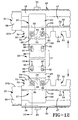
- stop members 35 are adjustable in length to accommodate different width tractor frame members as shown particularly in Figs. 10 - 12 as well as being movably adjustable along the longitudinal length of carrier assembly 15 as shown particularly in Fig. 9 .
- This width adjustment is obtained by the unique construction of mounting brackets 37.
- each mounting bracket 37 includes a mounting plate indicated generally at 80, having an in-turned end 81 which forms a U-shaped channel 82 for slidably receiving the outer end of leg 48 of U-shaped member 45 therein for slidably adjustably mounting bracket 37 on slide rail 40 ( Figs. 8 and 11 ).
- Mounting plate 80 includes a recessed area 83 formed between a pair of teeth 85 into which a tooth 24 extends for engagement with adjacent teeth 85 which engages spaced teeth 24 formed on rack 25 as shown particularly in Figs. 7 and 7A .
- Mounting plate 80 includes two pairs of holes 86 and 87 with holes 87 extending through teeth 85 for receiving bolts 88 and 89 respectively therethrough, which are threadably engaged in aligned holes 90 and 91 formed in a bottom clamping plate 93 ( Figs. 8 and 11 ).
- Mounting bracket 37 is secured in a selected position along rack 25 by receiving one of the rack teeth 24 in area 83 formed between the pair of teeth 85 formed on the bottom surface of mounting plate 80.
- Stop plate 36 is formed with a pair of opposed ends 95 and 96 ( Figs. 10 and 11 ), each of which is formed with a pair slotted openings 97 through which bolts 88 extend for securing plate 80 in an adjusted position on the ends of stop plate 36.
- stop member 35 is in its shortest position or narrowest width as indicated by bracket X, due to the location of bolts 88 within slotted openings 97.
- Fig. 12 shows stop member 35 in its longest position or greatest width as indicated by bracket Y, due to the location of stop bolts 89 within slotted openings 97 of stop plate 36.
- carrier assembly 15 is adaptable for use with tractor frames having various spacings without requiring substantial modifications thereto by use of bolts 88 and slots 97. This eliminates any welding as required in prior art carrier assemblies.
- Carrier assembly 15 is adaptable for various tractors having a range of frame spacings which heretofore required separate specially designed carriers for each particular tractor due to this difference in spacing requiring the welding and permanent fixing of cross members thereon.
- bolts 88 and 89 enable stop members 35 t be easily adjusted across the width of the slide rails 40 and longitudinally along tractor frame members 27 to enable carrier assembly 15 to be adaptable to various tractors and also to accommodate trailers having various king pin locations in order to achieve various weight distributions on the tractor rear wheels, as well as effecting the turning radius of the tractor with respect to the trailer.
- these adjustments were made permanently by welding fixtures to the carrier assembly and did not permit ease of adjustment in the location of end stop members as in the present invention which is accomplished by a plurality of bolts which are readily loosened and then tightened once the desired adjustments have been accomplished.
- plunger assembly 17 is easily adjusted as described above, enabling it to accommodate tractor frame members having various spacings therebetween without requiring substantial modifications to the plunger assembly which is achieved easily by the threaded adjustment of adjustment screw 26 in threaded opening 34 of plunger plate 23.
- rack 25 is formed by a plurality of rack segments 50 each of which includes a plurality of the individual teeth 24.
- the segments are placed in an abutting relationship along slide rail 40 as shown by joint 100.
- Each segment 50 is secured by a welded connection 52, with each welded connection consisting of top and bottom welds 53 as shown particularly in Figs. 5 , 8 , 11 and 13 .
- each rack segment 50 will have a length L ( Fig. 16 ) of approximately six inches.
- the improved carrier assembly for a fifth wheel assembly is simplified, provides an effective, safe, inexpensive, and efficient device which achieves all the enumerated objectives, provides for eliminating difficulties encountered with prior devices, and solves problems and obtains new results in the art.
Abstract
Description
- The invention relates generally to fifth wheel assemblies for coupling semi-trailers to tractors. More particularly, the invention relates to a carrier assembly which is mounted on the vehicle frame for movably supporting the fifth wheel supporting carriage. Even more particularly, the invention relates to such a carrier assembly which is adjustable for various width tractor frames and which facilitates positioning and replacement of the carriage on the trailer.
- Large highway freight trailers are usually coupled to a tractor by a fifth wheel assembly may include a top plate and a side bracket or carriage assembly having a locking device which engages the slide bracket in a selected position. The fifth wheel top plate is mounted on the carriage assembly which is movably adjustably mounted on a carrier assembly which is secured to the tractor frame.
- These slide plates or carrier assemblies are usually custom made to fit a particular type of tractor due to the size of the tractor frame. For certain applications it is necessary to adjust the position of the carriage assembly on the carrier assembly in order for the locking mechanism to be compatible with the location of the trailer king pin to provide a desired weight distribution on the rear suspension of the tractor. Likewise, this position affects the turning radius that can be achieved between the tractor and trailer. This adjustment of the carrier and carriage assemblies with respect to each other and to the tractor frame is relatively complicated and expensive due to the welding and unwelding of various parts.
- Carrier assemblies have various stop plates welded across the ends of the carrier to limit the position of the carriage assembly to prevent excessive movement of the carriage on the carrier assembly resulting in a dangerous turning radius and undesirable weight distribution on the tractor rear wheels. Heretofore, these stop members were welded into position and required breaking of the weld and rewelding the stop plate in a newly desired position, especially when replacing the slide plate assembly for maintenance or adaptability for use with a different trailer.
- Another problem with existing fifth wheel assemblies and in particular the carrier assembly therefor, is that the racks along which the carriage assembly is movably mounted and subsequently positioned by a pair of opposed plungers or other retention mechanism, are usually single linear lengths of a rack which require replacement of the entire rack should one of the teeth become damaged. This is an expensive procedure requiring numerous welds to be broken in order to remove the rack and then rewelded along the entire length once the new rack is put in place. Likewise, the cost of the new rack is expensive for replacing only one or several broken teeth.
- Still another problem with existing carrier assemblies is the unequal weight distribution of the carriage and slide plate on the carrier assembly resulting in increased maintenance problems.
- Another problem with existing fifth wheel assemblies is that the spring biased plungers which secure a carriage assembly in a fixed position on a carrier assembly, may require replacement in order to match a particular width trailer frame. This is expensive and undesirable. Furthermore, over time, the biasing force of the plunger biasing springs will weaken due to wear, temperature and the harsh environment in which they are located, which could cause premature release of the plungers from the carrier rails.
- Thus, the need exists for an improved carrier assembly for movably supporting a carriage assembly thereon of a tractor fifth wheel to eliminate problems with prior art carrier assemblies.
- The present invention provides a carrier assembly for movably supporting a fifth wheel assembly of a tractor trailer combination which is readily adjustably mounted on the spaced frame members of a tractor by a plurality of bolts along the length of the frame mounting angle.
- Another aspect of the invention provides a carrier assembly having adjustable stop members at opposed ends of the carrier which can be slidably adjusted easily along the length of the carrier in order to properly position the carriage assembly thereon, and which can be easily removed to permit replacement of the carriage and the slide plate assemblies.
- Still another feature of the invention is the forming of the carrier assembly slide rails as integral one piece members having a U-shaped portion on which the rack is welded whereby each of the slide rails is easily mounted on the tractor frame member and is able to receive and distribute the weight of the carrier in a more efficient and effective manner.
- A further aspect of the invention is forming the racks on the slide rails of a plurality of rack segments, each segment being secured to the slide rail by a pair of welds, whereby only a single segment need by replaced should one or more of the teeth be damaged avoiding the heretofore required replacement of the entire rack.
- A feature of the improved carrier assembly is the adjustability of the mounting brackets for the stop members enabling them to be mounted on tractor frame members of various spacings replacing the heretofore single piece stop members that are welded on the space frame members.
- Another aspect of the invention is providing locking plungers for securing the carriage assembly in a fixed position on the carrier assembly which are adjustable in length to compensate for different width trailer frames and to ensure a constant spring tensioning force for maintaining the plunger teeth in engagement with the teeth on the carrier assembly rails to prevent premature release.
- The foregoing advantages, construction and operation of the present invention will become more readily apparent from the following description and accompanying drawings.
- The preferred embodiment of the invention, illustrative of the best mode in which applicant contemplates applying the principles, is set forth in the following description and is shown in the drawings, and is particularly and distinctly pointed out and set forth in the appended claims.
-
Fig. 1 is a diagrammatic side elevational view of a tractor trailer combination connected together by a fifth wheel assembly; -
Fig. 2 is an enlarged fragmentary side elevational view of the fifth wheel assembly movably mounted on a carriage which is adjustably mounted on the improved carrier of the invention which is attached to the frame members of the tractor; -
Fig. 3 is an enlarged top plan view ofFig. 2 ; -
Fig. 4 is an enlarged fragmentary top plan view of the fifth wheel assembly with portions removed therefrom; -
Fig. 4A is an enlarged fragmentary view of the encircled portion ofFig. 4 ; -
Fig. 4B is an enlarged fragmentary sectional view taken online 4B-4B ofFig. 4A ; -
Fig. 5 is an enlarged fragmentary sectional view taken on line 5-5,Fig.4 ; -
Fig. 6 is a top plan view of the carrier assembly mounted on the spaced frame members of a tractor; -
Fig. 7 is an enlarged fragmentary view with portions broken away and in section, of the encircled portion ofFig. 6 ; -
Fig. 7A is a bottom plan view of the stop member mounting bracket ofFig. 7 ; -
Fig. 8 is an enlarged fragmentary sectional view taken on line 8-8,Fig. 7 ; -
Fig. 9 is a top plan view similar toFig. 6 showing one of the stop members of the carrier assembly in an adjusted position; -
Fig. 10 is an enlarged fragmentary top plan view showing the two mounting brackets of the carrier assembly stop member mounted on the spaced frame members of a tractor; -
Fig. 11 is an enlarged fragmentary sectional view taken on line 11-11,Fig. 10 ; -
Fig. 12 is a view similar toFig. 10 showing the stop member mounting brackets in an adjusted position from that ofFig. 10 ; -
Fig. 13 is an enlarged sectional view taken on line 13-13,Fig. 12 ; -
Fig. 14 is a fragmentary side elevational view of the carrier assembly mounted on one of the tractor frame members having a damaged rack segment; -
Fig. 15 is a view similar toFig. 14 showing removal of the damaged rack segment; and -
Fig. 16 is a view similar toFigs. 14 and 15 showing placement of a new rack segment on the carrier assembly. - Similar numerals refer to similar parts throughout the drawings.
-
Fig. 1 is a diagrammatic side elevational view of a usual tractor trailer combination indicated generally at 1, consisting of atrailer 2 and atractor 3 connected together byfifth wheel assembly 4. Referring toFigs. 2 and3 ,fifth wheel assembly 4 consists of a usualtop plate assembly 5 having a V-shaped slottedopening 6 for receiving a king pin (not shown) oftrailer 2 within the locking opening 8 of a locking mechanism. The particularly construction oftop plate 5 and the manner ofoperating locking mechanism 9 are well known in the art, and thus are not described in further detail.Top plate 5 is pivotally mounted at 10 on a pair of spacedpedestals 11 to permit pivotal movement of the top plate.Pedestals 11 are mounted on a slide bracket or carriage assembly 13 (Fig. 4 ) which is adjustably movably mounted on the improved slide plate or carrier assembly, indicated generally at 15. The construction ofcarriage assembly 13 is well known in the art and is only partially shown inFig. 4 and briefly described below. -
Carriage assembly 13 has a plunger assembly indicated generally at 17, which includes aplunger support plate 18 and a pair ofmovable plungers 19 connected together by anadjustable link assembly 20. Eachplunger 19 includes a plurality ofteeth 22 which are formed on aplunger plate 23 which is mounted on the outer end of an adjustment screw 26 (Fig. 4B ) which is pivotally connected to a pair oflinks 31 which are pivotally connected by a pin 21 (Fig. 4 ) at the center ofplunger assembly 17. The opposite ends of eachlink 31 are pivotally connected to adjustment screws 26 bypins 32.Teeth 22 are engageable withteeth 24 of a pair of spacedracks 25 to securecarriage assembly 13 in an adjusted position oncarrier assembly 15. - In accordance with one of the features of the invention,
adjustment screw 26 includes a threadedend 33 which is threadably received within a threadedopening 34 formed in plunger plate 23 (Fig. 4B ). This enables the length ofplunger assembly 17 to be adjusted for various width trailer frames and also enablesplate 23 to be adjusted with respect to spacedracks 25 as shown by arrow A,Fig. 4B , to change the tension in compression coil springs 39 which biasplates 23 and correspondingteeth 22 toward engagement with the teeth ofrack 25. The inboard end of eachplate 23 is slidably located within anopening 44A of mountingplate 44 which is welded toplunger support plate 18. -
Carriage assembly 13 includes a pair of steppedplates 28 on which pedestals 11 are mounted and further includes across plate 29 extending betweenplates 28 for stabilizingcarriage assembly 13 together withplunger support plate 18. Alink 30 extends diagonally betweencross plate 29 andplunger support plate 18 to stabilizecarriage assembly 13.Carriage assembly 13 includes a pair of mountingbrackets 55 extending across the underside of steppedplate 28 for movably mountingcarriage assembly 13 on carrier assembly 15 (Fig. 5 ). Only onebracket 55 is shown inFig. 4 and is described further below. -
Improved carrier assembly 15 is shown particularly inFig. 6 . In accordance with one of the features of the Invention it includes a pair of adjustableend stop members 35, each of which includes astop plate 36 and a pair ofend mounting brackets 37.Carrier assembly 15 further includes a pair of improved slide rails indicated generally at 40, which are mounted on spacedtractor frame members 27 for movably supportingcarriage assembly 13 onrails 40 as shown inFig. 5 .Tractor frame members 27 are usually inverted U-shaped or L-shaped beams as shown inFig. 5 having a vertically extendingleg 27A and a horizontal top leg orwall 27B. Slide rails 40 are preferably substantially similar to each other, and thus only one is described in detail and shown in the drawings. - In accordance with another feature of the invention, slide rail 40 (
Figs. 2 ,5 and6 ) is formed as an integral one piece member of rigid metal and includes a flat vertically extending mountingleg 41 containing a plurality of mountingholes 42 for receiving mountingbolts 43 therethrough for rigidly attachingslide rail 40 totractor frame leg 27A.Slide rail 40 further includes aU-shaped member 45 formed by a pair of spacedlegs U-shaped channel 49 therein.Leg 46 extends from mountingleg 41 and forms a substantial 90° angle therebetween and extends along end and rests upontop surface 38 oftractor frame leg 27B. - In accordance with another feature of the
invention rack 25 is formed by a plurality ofrack segments 50 which are mounted onbase 48 ofU-shaped member 45 by a plurality of weldedconnections 52. Preferably, there are at least two weldedconnections 52 for eachrack segment 50, each connection having upper and lower welds 53. Eachrack segment 50 includes a plurality of theindividual teeth 24 which extend inboard fromU-shaped member 45. In the preferredembodiment rack segments 50 have a linear length of approximately six inches. - Referring particularly to
Figs. 4 and5 ,carriage assembly 13 is adjustably movably mounted oncarrier assembly 15 by mountingbrackets 55 which extend generally throughout the lengthpedestal support plate 28 and are secured thereto by pairs ofbolts 58.Bolts 58 also extend through and connectlink 31 to an outwardly projectingtab 61, a plurality of which extend outwardly from the corners ofplunger support plate 18.Bolts 58 also connecttabs 56 to clamp 55, and to a generallyU-shaped bracket 57 through whichplunger teeth segments 23 extend for engagement withracks 25. - Each mounting bracket 55 (
Fig. 5 ) further includes aU-shaped channel 64 formed by alower leg 62 and steppedpedestal plate 28.Plate 28 terminates in an outboard U-shapedchannel forming member 67 having a lower leg 68 which forms U-shaped channel 69 with steppedplate 28. The cross sectional configuration ofbrackets 55 will remain similar to that shown inFig. 5 except for a short section (not shown) opposite ofplunger segments 23 whereon thevertical wall 54 extending betweenbracket 57 andpedestal plate 28 is cut away to permit the passage ofplunger teeth segment 23 therethrough. - As shown particularly in
Fig. 5 , mountingbracket 55 is secured in a selected fixed position onslide rail 40 by a threadedset bolt 72 which is adjustably engaged in athread hole 74 formed inmember 67. The inner end ofbolt 72 engages the outer end ofleg 47 ofslide rail 40, and is secured in the fixed clamping engagement therewith by alock nut 73.Leg 47 ofU-shaped member 45 ofrail 40 is received in U-shaped channel 69 withteeth 24 ofrack segments 50 extending intoU-shaped channel 64. - As can be seen in
Fig. 5 ,slide rail 40 provides various areas on which the weight ofcarriage assembly 13 is supported, such as the upper surfaces ofleg 47 and ofteeth 24,leg 27B engaging leg 62, andleg 46 supporting bracket leg 68 ontop wall 27B oftractor frame 27. These various areas of support are provided byslide rail 40 for evenly distributing and supporting the weight ofcarriage assembly 13 through mountingbrackets 55. - In accordance with a further feature of the invention, stop
members 35 are adjustable in length to accommodate different width tractor frame members as shown particularly inFigs. 10 - 12 as well as being movably adjustable along the longitudinal length ofcarrier assembly 15 as shown particularly inFig. 9 . This width adjustment is obtained by the unique construction of mountingbrackets 37. Referring particularly toFigs. 6 - 12 , each mountingbracket 37 includes a mounting plate indicated generally at 80, having an in-turnedend 81 which forms aU-shaped channel 82 for slidably receiving the outer end ofleg 48 ofU-shaped member 45 therein for slidably adjustably mountingbracket 37 on slide rail 40 (Figs. 8 and 11 ). Mountingplate 80 includes a recessedarea 83 formed between a pair ofteeth 85 into which atooth 24 extends for engagement withadjacent teeth 85 which engages spacedteeth 24 formed onrack 25 as shown particularly inFigs. 7 and 7A . Mountingplate 80 includes two pairs ofholes holes 87 extending throughteeth 85 for receivingbolts holes Figs. 8 and 11 ). Mountingbracket 37 is secured in a selected position alongrack 25 by receiving one of therack teeth 24 inarea 83 formed between the pair ofteeth 85 formed on the bottom surface of mountingplate 80. - Stop
plate 36 is formed with a pair of opposed ends 95 and 96 (Figs. 10 and11 ), each of which is formed with a pair slottedopenings 97 through whichbolts 88 extend for securingplate 80 in an adjusted position on the ends ofstop plate 36. As shown inFig. 10 ,stop member 35 is in its shortest position or narrowest width as indicated by bracket X, due to the location ofbolts 88 within slottedopenings 97.Fig. 12 shows stopmember 35 in its longest position or greatest width as indicated by bracket Y, due to the location ofstop bolts 89 within slottedopenings 97 ofstop plate 36. - Thus,
carrier assembly 15 is adaptable for use with tractor frames having various spacings without requiring substantial modifications thereto by use ofbolts 88 andslots 97. This eliminates any welding as required in prior art carrier assemblies.Carrier assembly 15 is adaptable for various tractors having a range of frame spacings which heretofore required separate specially designed carriers for each particular tractor due to this difference in spacing requiring the welding and permanent fixing of cross members thereon. Likewise,bolts tractor frame members 27 to enablecarrier assembly 15 to be adaptable to various tractors and also to accommodate trailers having various king pin locations in order to achieve various weight distributions on the tractor rear wheels, as well as effecting the turning radius of the tractor with respect to the trailer. Heretofore, these adjustments were made permanently by welding fixtures to the carrier assembly and did not permit ease of adjustment in the location of end stop members as in the present invention which is accomplished by a plurality of bolts which are readily loosened and then tightened once the desired adjustments have been accomplished. - Likewise,
plunger assembly 17 is easily adjusted as described above, enabling it to accommodate tractor frame members having various spacings therebetween without requiring substantial modifications to the plunger assembly which is achieved easily by the threaded adjustment ofadjustment screw 26 in threadedopening 34 ofplunger plate 23. - In accordance with still another feature of the invention as shown in
Figs. 14-16 ,rack 25 is formed by a plurality ofrack segments 50 each of which includes a plurality of theindividual teeth 24. The segments are placed in an abutting relationship alongslide rail 40 as shown by joint 100. Eachsegment 50 is secured by a weldedconnection 52, with each welded connection consisting of top andbottom welds 53 as shown particularly inFigs. 5 ,8 ,11 and13 . In the preferred embodiment, eachrack segment 50 will have a length L (Fig. 16 ) of approximately six inches. - This feature enables a damaged tooth or several teeth as shown by
rack segment 50A inFig. 15 , to be easily replaced by anundamaged rack segment 50B requiring only two weldedconnections 52 to be replaced and reapplied. This eliminates the heretofore replacement of theentire rack 25, which in prior carrier constructions was a single longitudinally extending rack formed as a single piece extending throughout the length of the carrier assembly. Thus, replacement of only one short rack segment is considerably cheaper and easier to accomplish then replacing the entire rack as required in prior carrier assemblies. - Accordingly, the improved carrier assembly for a fifth wheel assembly is simplified, provides an effective, safe, inexpensive, and efficient device which achieves all the enumerated objectives, provides for eliminating difficulties encountered with prior devices, and solves problems and obtains new results in the art.
- In the foregoing description, certain terms have been used for brevity, clearness, and understanding; but no unnecessary limitations are to be implied therefrom beyond the requirement of the prior art, because such terms are used for descriptive purposes and are intended to be broadly construed.
- Moreover, the description and illustration of the invention is by way of example, and the scope of the invention is not limited to the exact details shown or described.
- Having now described the features, discoveries, and principles of the invention, the manner in which the improved carrier assembly is constructed and used, the characteristics of the construction, and the advantageous new and useful results obtained; the new and useful structures, devices, elements, arrangements, parts, and combinations are set forth in the appended claims.
Claims (17)
- A carrier assembly (15) for movably supporting a fifth wheel assembly (4) on a pair of spaced frame members (27) of a tractor (3) comprising- a pair of slide rails (40) adapted to be mounted on the spaced frame members (27), each of said slide rails (40) being a integral one-piece member having an attachment leg (41) and a generally U-shaped member (45) extending inboard from the attachment leg (41),- a rack (25) containing a plurality of teeth (24) attached to each of the U-shaped rails (45) and extending inboard therefrom and- at least one stop plate assembly (35) extending between the pair of slide rails (40),characterized in that,
said one stop plate assembly (35) is secured in a selected position on said slide rails (40) with adjustable mounting brackets (37). - The carrier assembly according to claim 1, characterized in that, said stop plate assembly (35) includes a stop plate (36) extending between the mounting brackets (37), in which each of the mounting brackets (37) include a mounting plate (80) which is secured to opposite ends (95, 96) of the stop plate (36), and in which at least one of the mounting plates (80) is adjustably mounted on the stop plate (36).
- The carrier assembly according to claim 2, characterized in that, at least one of the mounting brackets (37) is formed with a curved end which slidably engages an outer edge of the U-shaped member (45) of the slide rail (40); and at least one tooth (85) is formed on said one mounting bracket (37) and engage selected teeth (24) of the rack (25).
- In combination a pair of spaced frame members (27) on the rear of a tractor (3) and carrier assembly (15) for movably supporting a fifth wheel assembly (4) on said frame members (27) comprising:- a pair of slide rails (40) adapted to be mounted on the spaced frame member (27), each of said slide rails (40) being an integral one-piece member having an attachment leg (41) and a generally U-shaped member (45) extending from said attachment leg (41),- a rack (25) containing a plurality of teeth (24) attached to each of the U-shaped members (45) and extending inboard therefrom and- at least a stop plate assembly (35) extending between the pair of slide rails (40),characterized in that,
said stop plate assembly (35) includes a stop plate (36) and a pair of adjustable end mounting brackets (37), wherein said stop plate (36) is secured to the mounting brackets (37) by fasteners. - The combination according to claim 4, characterized in that, the stop plate assembly mounting brackets (37) are adjustably secured to opposite ends of the stop plate (36); and said mounting brackets (37) are formed with curved ends; and the said curved ends are slidably received in the U-shaped members (45) of the slide rails (40).
- The combination according to claim 4, characterized in that, each of the frame members (27) has a side wall (27A) and a top wall (27B); the attachment leg (41) of the slide rail (40) extends along and is secured to the side wall (27A) of the frame member (27); and the U-shaped member (45) rests upon the top wall (27B) of said frame member.
- The combination according to claim 6, characterized in that, the attachment leg (41) and frame member side wall (27A) are formed with a plurality of spaced holes (42) and fasteners (43) extend through certain of said holes (42) for securing the slide rail (40) on the frame member (27).
- The combination according to claim 5, characterized in that, slotted openings (97) are formed in one of the stop plate (36) and mounting brackets (37); and holes are formed in the other of said stop plate (36) and mounting brackets (37); and fasteners (88) extend through certain of said slotted openings (97) and holes to adjustably mount the stop plate (36) on the mounting brackets (37).
- The combination according to claim 4, characterized in that, a carriage assembly (13) is movably mounted on the slide rails (40) by spaced mounting brackets (55); said mounting brackets (55) each include a first channel (64) for slidably receiving the teeth (24) of the rack (25) therein; and a second channel (69) is formed in each of the mounting brackets (55) for receiving an end of the U-shaped member (45) therein.
- The combination according to claim 9, characterized in that, clamping bolts (72) engage the end of the U-shaped member (45) to secure the mounting bracket (55) on the slide rail (40).
- An adjustable stop member (35) for mounting on a pair of spaced slide rails (40) of a carrier assembly (15) which movably supports a fifth wheel assembly (4) thereon, said stop member (35) comprising
a plate (36) having a pair of opposed ends (95, 96), said plate (36) adapted to extend substantially between the slide rails (40) of the carrier assembly (15),
characterized in that,
a bracket (37) is mounted on each of the plate ends (95, 96) for mounting the plate (36) on the slide rails (40), at least one of said brackets (37) having an adjusting mechanism for adjusting the length of the stop member (35). - The stop member (35) according to claim 11, characterized in that, each of the brackets (37) is formed with a pair of teeth (85) and a plurality of mounting holes (86, 87).
- The stop member (35) according to claim 12, characterized in that, the stop member (35) includes a clamp plate (93) for securing each of the brackets (37) on the slide rails (40).
- The stop member (35) according to claim 11, characterized in that, one of the plate ends (95, 96) and brackets (37) is formed with slotted openings (97) and the other of said ends (95, 96) and brackets (37) is formed with holes; and fasteners extend through said slotted openings (97) and holes to provide the adjusting mechanism.
- A plunger assembly (17) for securing a carriage assembly (13) of a fifth wheel (4) in a fixed position on a carrier assembly (15) mounted on a trailer frame (27), said plunger assembly (17) comprising:- a pair of spaced plunger plates (23) each having at least one tooth (22) for engaging the carrier assembly (15) and- a linkage (20) extending between the pair of plunger plates (23),characterized in that,
said carriage assembly (13) is adjustably movably mounted on the carrier assembly (15) by mounting brackets (55) comprising an adjusting mechanism for varying the spacing between the plunger plates (23). - The plunger assembly (17) according to claim 15, characterized in that, the adjusting mechanism includes a threaded connection (33, 34) between the linkage (20) and the plunger plates (23).
- The plunger assembly (17) according to claim 15, characterized in that, the plunger assembly (17) includes a spring (39) which biases the said one tooth (22) toward engagement with the carrier assembly (15).
Applications Claiming Priority (2)
| Application Number | Priority Date | Filing Date | Title |
|---|---|---|---|
| US09/798,760 US6488305B2 (en) | 2001-03-02 | 2001-03-02 | Carrier assembly for movably supporting a fifth wheel assembly |
| EP02723295A EP1409329B1 (en) | 2001-03-02 | 2002-03-01 | Carrier assembly for movably supporting a fifth wheel assembly |
Related Parent Applications (2)
| Application Number | Title | Priority Date | Filing Date |
|---|---|---|---|
| EP02723295A Division EP1409329B1 (en) | 2001-03-02 | 2002-03-01 | Carrier assembly for movably supporting a fifth wheel assembly |
| EP02723295.8 Division | 2002-03-01 |
Publications (3)
| Publication Number | Publication Date |
|---|---|
| EP1995158A2 true EP1995158A2 (en) | 2008-11-26 |
| EP1995158A3 EP1995158A3 (en) | 2009-02-18 |
| EP1995158B1 EP1995158B1 (en) | 2011-06-22 |
Family
ID=25174192
Family Applications (2)
| Application Number | Title | Priority Date | Filing Date |
|---|---|---|---|
| EP02723295A Expired - Lifetime EP1409329B1 (en) | 2001-03-02 | 2002-03-01 | Carrier assembly for movably supporting a fifth wheel assembly |
| EP08105251A Expired - Lifetime EP1995158B1 (en) | 2001-03-02 | 2002-03-01 | Carriage assembly for a fifth wheel and adjustable stop member therefor |
Family Applications Before (1)
| Application Number | Title | Priority Date | Filing Date |
|---|---|---|---|
| EP02723295A Expired - Lifetime EP1409329B1 (en) | 2001-03-02 | 2002-03-01 | Carrier assembly for movably supporting a fifth wheel assembly |
Country Status (6)
| Country | Link |
|---|---|
| US (5) | US6488305B2 (en) |
| EP (2) | EP1409329B1 (en) |
| AT (2) | ATE513728T1 (en) |
| DE (1) | DE60232882D1 (en) |
| ES (1) | ES2327214T3 (en) |
| WO (1) | WO2002070328A1 (en) |
Cited By (1)
| Publication number | Priority date | Publication date | Assignee | Title |
|---|---|---|---|---|
| US8333399B2 (en) | 2009-09-22 | 2012-12-18 | International Truck Intellectual Property Company, Llc | Slidably adjustable fifth wheel hitch assembly for a vehicle and control system for the same |
Families Citing this family (33)
| Publication number | Priority date | Publication date | Assignee | Title |
|---|---|---|---|---|
| DE19944684C1 (en) * | 1999-09-17 | 2000-11-30 | Jost Werke Ag | Sliding device for saddle coupliing has base frame with 2 parallel angle profiles supporting sliding upper part which is adjustable in longitudinal and transverse directions |
| US6736420B2 (en) * | 2000-03-03 | 2004-05-18 | Jost International Corporation | Carrier assembly for a fifth wheel |
| CA2421419C (en) * | 2003-03-07 | 2006-10-17 | Arctic Manufacturing Ltd. | Slide assembly |
| US7296817B1 (en) * | 2004-09-15 | 2007-11-20 | Fontaine International | Fifth wheel slide rail stop block |
| DE102004045662B4 (en) | 2004-09-18 | 2008-10-30 | Jost-Werke Gmbh | Adjustment device, control device and device for reducing the air resistance of a semitrailer |
| US7806424B2 (en) * | 2004-11-24 | 2010-10-05 | Modern Equipments Sales, L.C. | Fifth wheel hitch assembly |
| US20060202443A1 (en) * | 2005-03-09 | 2006-09-14 | The Holland Group, Inc. | Fifth wheel slider assembly |
| DE102005040146B4 (en) * | 2005-08-25 | 2010-06-10 | Jost-Werke Gmbh | Displacement device for fifth wheel couplings |
| US7448639B1 (en) | 2005-12-08 | 2008-11-11 | Fontaine International | Fifth wheel mounting bracket |
| DE102005060124B4 (en) * | 2005-12-16 | 2011-05-05 | Jost-Werke Gmbh | Displacement device for a fifth wheel arranged on a towing vehicle |
| US7506886B2 (en) * | 2006-02-01 | 2009-03-24 | Victoria Industries Ltd. | Slidable fifth-wheel hitch |
| US7516974B1 (en) * | 2006-03-03 | 2009-04-14 | Fontaine International | Fifth wheel assembly |
| US7726678B1 (en) | 2006-09-19 | 2010-06-01 | Hensley Manufacturing, Inc. | Sliding fifth wheel assembly |
| GB0709876D0 (en) * | 2007-05-23 | 2007-07-04 | Thomson Jim | 5th wheel setting guide for tractor-trailer combination |
| US7699334B1 (en) | 2007-11-21 | 2010-04-20 | Fontaine Fifth Wheel Co. | Fifth wheel slide rail |
| US8317452B2 (en) * | 2007-12-18 | 2012-11-27 | Lundin Recovery Equipment Llc | Converter dolly for a tandem trailer |
| US9616943B2 (en) | 2008-01-30 | 2017-04-11 | Volvo Group North America, Llc | Tractor trailer gap control system |
| US7992886B2 (en) * | 2008-12-15 | 2011-08-09 | Fontaine Fifth Wheel Co. | Articulated fifth wheel selective adjustment means |
| US8511703B2 (en) * | 2009-10-07 | 2013-08-20 | The Coast Distribution System, Inc. | Sliding hitch assembly |
| US20110210529A1 (en) * | 2010-02-26 | 2011-09-01 | Daimler Trucks North America LLC. | Method and apparatus for adjusting the gap of a fifth wheel of a vehicle |
| DE102010039578B4 (en) * | 2010-08-20 | 2014-12-11 | Jost-Werke Gmbh | bearing arrangement |
| US8573627B2 (en) * | 2010-11-04 | 2013-11-05 | Saf-Holland, Inc. | Fifth wheel support assembly |
| US20130297154A1 (en) * | 2011-01-17 | 2013-11-07 | Volvo Group North America, Llc | Tractor trailer gap control system |
| CA2791960C (en) * | 2011-10-03 | 2015-04-14 | The Coast Distribution System, Inc. | Sliding hitch assembly |
| US8720931B2 (en) * | 2011-11-02 | 2014-05-13 | Saf-Holland, Inc. | Tilt limiting assembly for fifth wheel hitch assembly |
| US9656702B2 (en) * | 2011-11-07 | 2017-05-23 | Saf-Holland, Inc. | Fifth wheel hitch support assembly |
| US8827297B2 (en) * | 2012-04-27 | 2014-09-09 | Saf-Holland, Inc. | Fifth wheel support assembly with slide limiter |
| US9126464B2 (en) * | 2012-06-12 | 2015-09-08 | Saf-Holland, Inc. | Fifth wheel assembly with automatic lockouts |
| US8960705B2 (en) | 2012-10-26 | 2015-02-24 | B & W Custom Truck Beds, Inc. | Sliding hitch with automatic arming latch |
| US9511804B2 (en) | 2013-03-15 | 2016-12-06 | Cequent Performance Products, Inc. | Automatic rolling fifth wheel hitch |
| WO2014189762A1 (en) * | 2013-05-22 | 2014-11-27 | Saf-Holland, Inc. | Fifth wheel hitch assembly having direct-mount mounting brackets |
| US9186942B1 (en) * | 2013-12-26 | 2015-11-17 | Camco Manufacturing, Inc. | Fifth wheel slideable hitch assembly |
| CN108995488B (en) * | 2018-10-25 | 2021-02-02 | 安徽江淮汽车集团股份有限公司 | Electric tractor assembly with adjustable axis position |
Citations (9)
| Publication number | Priority date | Publication date | Assignee | Title |
|---|---|---|---|---|
| GB191320325A (en) * | 1913-09-09 | 1914-09-03 | Andrew William Blake | A New or Improved Vehicle for Lifting and Transporting Cable Drums and the like. |
| US1425999A (en) * | 1922-08-15 | Trttckxng mechanism | ||
| GB522812A (en) * | 1938-12-17 | 1940-06-27 | Simeon Branskey | Improvements relating to towing-bars for trailer vehicles |
| US3606384A (en) * | 1970-05-18 | 1971-09-20 | John P K Fontaine | Slide mount for fifth wheels |
| US3729214A (en) * | 1971-08-27 | 1973-04-24 | Amsted Ind Inc | Adjustable fifth wheel mounting |
| DE7320517U (en) * | 1973-06-01 | 1973-11-08 | Westfalia-Werke F Knoebel & Soehne Kg | Holding device for a trailer coupling on motor vehicles |
| US4443025A (en) * | 1982-03-03 | 1984-04-17 | Holland Hitch Company | Fifth wheel assembly |
| DE29616145U1 (en) * | 1996-09-18 | 1996-10-31 | Bpw Bergische Achsen Kg | Device for receiving a trailer coupling |
| DE19944684C1 (en) * | 1999-09-17 | 2000-11-30 | Jost Werke Ag | Sliding device for saddle coupliing has base frame with 2 parallel angle profiles supporting sliding upper part which is adjustable in longitudinal and transverse directions |
Family Cites Families (36)
| Publication number | Priority date | Publication date | Assignee | Title |
|---|---|---|---|---|
| US2831735A (en) * | 1954-03-15 | 1958-04-22 | Utility Trailer Mfg Company | Longitudinally adjustable running gear for vehicles |
| US2985463A (en) * | 1958-08-01 | 1961-05-23 | Holland Hitch Co | Fifth wheel assembly |
| US3077357A (en) * | 1960-04-13 | 1963-02-12 | Inertia Matic Inc | Fifth-wheel assembly |
| US3241860A (en) * | 1963-09-12 | 1966-03-22 | Robert N Janeway | Tractor-trailer fifth wheel coupling |
| US3369825A (en) * | 1966-04-27 | 1968-02-20 | Lloyd J. Wolf | Adjustable fifth wheel mount |
| US3609825A (en) * | 1969-01-21 | 1971-10-05 | Vlash A Pullos | Underwater release |
| US3791664A (en) * | 1970-08-27 | 1974-02-12 | Freightliner Corp | Self-leveler |
| US3722914A (en) * | 1971-06-10 | 1973-03-27 | Dayton Steel Foundry Co | Slider mount for fifth wheels |
| US3811706A (en) * | 1973-01-02 | 1974-05-21 | Schott Ind Inc | Trailer hitch |
| US3861709A (en) * | 1973-07-12 | 1975-01-21 | Amsted Ind Inc | Shiftable fifth wheel construction |
| US3893710A (en) * | 1974-06-03 | 1975-07-08 | Amsted Ind Inc | Slack-free fifth wheel slider |
| CH630857A5 (en) * | 1978-08-24 | 1982-07-15 | Fischer Ag Georg | Displacement device for the fifth-wheel coupling on a semitrailer motor vehicle |
| US4429892A (en) * | 1981-06-25 | 1984-02-07 | Frampton William H | Sliding fifth wheel |
| US4614355A (en) * | 1984-05-21 | 1986-09-30 | Koch Richard L | Fifth-wheel assembly |
| CA1328476C (en) * | 1986-04-23 | 1994-04-12 | Boyd B. Nash | Self unloading multiple trailer arrangement |
| US4762334A (en) * | 1987-11-03 | 1988-08-09 | Amsted Industries Incorporated | Fifth wheel bracket mounting assembly |
| US4858804A (en) * | 1988-01-05 | 1989-08-22 | Sharp Jr Kenneth J | Method and apparatus for separating interconnected stacks |
| US4871182A (en) | 1988-02-26 | 1989-10-03 | Amsted Industries Incorporated | Fifth wheel unlocking and safety latch device |
| US5092733A (en) * | 1989-04-26 | 1992-03-03 | Kabushiki Kaisha Hikoma Seisakusho | Tool controlling mechanisms for excavator with telescopic arm |
| US5028067A (en) | 1990-04-16 | 1991-07-02 | Amsted Industries Incorporated | Automatic fifth wheel safety lock device |
| US5176396A (en) | 1991-04-03 | 1993-01-05 | Amsted Industries Incorporated | Fifth wheel unlocking device with fluid powered redundancy |
| DE4206565C2 (en) * | 1992-03-02 | 1995-01-19 | Marantec Antrieb Steuerung | Sliding gate |
| US5265900A (en) * | 1992-10-19 | 1993-11-30 | Stack Jr Robert L | Sliding fifth wheel rack stop block |
| DE9305395U1 (en) * | 1993-04-08 | 1994-08-11 | Machill Rolf | Power transmission element on a sliding gate |
| CA2130532C (en) * | 1993-09-27 | 2006-01-31 | Lyle L. Cattau | Fifth wheel slide assembly |
| US5344173A (en) * | 1993-11-29 | 1994-09-06 | Beeler Dwight E | Fifth wheel slide stop |
| US5472223A (en) | 1993-11-30 | 1995-12-05 | Amsted Industries Incorporated | Air operated fifth wheel |
| US5368324A (en) * | 1994-01-10 | 1994-11-29 | Amsted Industries Incorporated | Mounting system for fifth wheels |
| CA2138591C (en) * | 1994-12-20 | 1999-06-15 | Herman Ophardt | Modular shuttle conveyor |
| DE19606374A1 (en) * | 1996-02-21 | 1997-08-28 | Thomas Kniep | Saddle support for a tractor unit |
| US5765849A (en) * | 1996-04-24 | 1998-06-16 | Fontaine Fifth Wheel Co. | Fifth wheel bracket |
| US5772229A (en) * | 1996-06-21 | 1998-06-30 | Cattau; Lyle L. | Sliding hitch |
| US5871182A (en) * | 1997-02-05 | 1999-02-16 | Fluoroware, Inc. | Modular tubing support and constrainment device |
| US6707070B2 (en) * | 1998-09-25 | 2004-03-16 | Riken | Wavelength-tunable light emitting device |
| US6179316B1 (en) | 1999-02-25 | 2001-01-30 | Holland Hitch Company | Stepped lock plunger fifth wheel hitch |
| US20040021290A1 (en) * | 2001-06-07 | 2004-02-05 | Hicks William J. | Integrated fifth wheel and frame suspension |
-
2001
- 2001-03-02 US US09/798,760 patent/US6488305B2/en not_active Expired - Fee Related
-
2002
- 2002-03-01 WO PCT/US2002/006298 patent/WO2002070328A1/en not_active Application Discontinuation
- 2002-03-01 DE DE60232882T patent/DE60232882D1/en not_active Expired - Lifetime
- 2002-03-01 ES ES02723295T patent/ES2327214T3/en not_active Expired - Lifetime
- 2002-03-01 EP EP02723295A patent/EP1409329B1/en not_active Expired - Lifetime
- 2002-03-01 AT AT08105251T patent/ATE513728T1/en not_active IP Right Cessation
- 2002-03-01 AT AT02723295T patent/ATE435802T1/en not_active IP Right Cessation
- 2002-03-01 EP EP08105251A patent/EP1995158B1/en not_active Expired - Lifetime
- 2002-07-11 US US10/194,036 patent/US7108274B2/en not_active Expired - Fee Related
- 2002-07-11 US US10/194,037 patent/US20020175494A1/en not_active Abandoned
- 2002-07-11 US US10/194,546 patent/US20020175495A1/en not_active Abandoned
-
2006
- 2006-08-24 US US11/509,462 patent/US20070007747A1/en not_active Abandoned
Patent Citations (9)
| Publication number | Priority date | Publication date | Assignee | Title |
|---|---|---|---|---|
| US1425999A (en) * | 1922-08-15 | Trttckxng mechanism | ||
| GB191320325A (en) * | 1913-09-09 | 1914-09-03 | Andrew William Blake | A New or Improved Vehicle for Lifting and Transporting Cable Drums and the like. |
| GB522812A (en) * | 1938-12-17 | 1940-06-27 | Simeon Branskey | Improvements relating to towing-bars for trailer vehicles |
| US3606384A (en) * | 1970-05-18 | 1971-09-20 | John P K Fontaine | Slide mount for fifth wheels |
| US3729214A (en) * | 1971-08-27 | 1973-04-24 | Amsted Ind Inc | Adjustable fifth wheel mounting |
| DE7320517U (en) * | 1973-06-01 | 1973-11-08 | Westfalia-Werke F Knoebel & Soehne Kg | Holding device for a trailer coupling on motor vehicles |
| US4443025A (en) * | 1982-03-03 | 1984-04-17 | Holland Hitch Company | Fifth wheel assembly |
| DE29616145U1 (en) * | 1996-09-18 | 1996-10-31 | Bpw Bergische Achsen Kg | Device for receiving a trailer coupling |
| DE19944684C1 (en) * | 1999-09-17 | 2000-11-30 | Jost Werke Ag | Sliding device for saddle coupliing has base frame with 2 parallel angle profiles supporting sliding upper part which is adjustable in longitudinal and transverse directions |
Cited By (2)
| Publication number | Priority date | Publication date | Assignee | Title |
|---|---|---|---|---|
| US8333399B2 (en) | 2009-09-22 | 2012-12-18 | International Truck Intellectual Property Company, Llc | Slidably adjustable fifth wheel hitch assembly for a vehicle and control system for the same |
| US8348297B2 (en) | 2009-09-22 | 2013-01-08 | International Truck Intellectual Property Company, Llc | Slidably adjustable fifth wheel hitch assembly for a vehicle and control system for the same |
Also Published As
| Publication number | Publication date |
|---|---|
| US7108274B2 (en) | 2006-09-19 |
| DE60232882D1 (en) | 2009-08-20 |
| ATE435802T1 (en) | 2009-07-15 |
| EP1409329A4 (en) | 2006-05-17 |
| WO2002070328A1 (en) | 2002-09-12 |
| US6488305B2 (en) | 2002-12-03 |
| EP1409329B1 (en) | 2009-07-08 |
| EP1409329A1 (en) | 2004-04-21 |
| EP1995158A3 (en) | 2009-02-18 |
| EP1995158B1 (en) | 2011-06-22 |
| ATE513728T1 (en) | 2011-07-15 |
| US20020175494A1 (en) | 2002-11-28 |
| US20020175495A1 (en) | 2002-11-28 |
| US20020121762A1 (en) | 2002-09-05 |
| US20020175493A1 (en) | 2002-11-28 |
| ES2327214T3 (en) | 2009-10-27 |
| US20070007747A1 (en) | 2007-01-11 |
Similar Documents
| Publication | Publication Date | Title |
|---|---|---|
| US6488305B2 (en) | Carrier assembly for movably supporting a fifth wheel assembly | |
| US5950971A (en) | Assembly for and method of mounting a suspension member to an axle housing | |
| US7513517B2 (en) | Bar pin attachment for bush assembly | |
| AU2006223385B2 (en) | Fifth wheel slider assembly | |
| AU2001255852B2 (en) | Axle clamp attachment system | |
| US5337997A (en) | Extruded aluminum spring hanger | |
| US7175190B2 (en) | Horizontal mount of suspension element to axle | |
| US7073804B2 (en) | Fender assembly and adjustable mounting bracket therefor | |
| CA1283137C (en) | Fifth wheel bracket mounting assembly | |
| US4991872A (en) | Low-bed trailer suspension system | |
| US8152200B2 (en) | Heavy equipment trailer with deck extension | |
| US6843490B2 (en) | Suspension beam and bush attachment assembly | |
| EP1233901B1 (en) | Connection arrangement comprising a fifth wheel | |
| EP0947388A1 (en) | Support system for utility vehicles | |
| US20230278379A1 (en) | Bracket assembly for a weight distribution system | |
| USRE33681E (en) | Apparatus for mounting a trailer hitch on a vehicle | |
| KR102570091B1 (en) | Jig system for installing wheel brake module and installing method of wheel brake module using it | |
| CZ51394A3 (en) | Cross beam with mounting elements for fastening a castor undercarriage and hinges, and process for producing such cross beam | |
| SU1601014A1 (en) | Grawler tractor | |
| AU733936B2 (en) | Roof rack foot and roof rack | |
| FI79737B (en) | ANALYZING FOER AVESTANDE AV SKENOR. | |
| MXPA97003002A (en) | Mensula or support for horizontal ring of avant | |
| JPH08295209A (en) | Car body fixing device |
Legal Events
| Date | Code | Title | Description |
|---|---|---|---|
| PUAI | Public reference made under article 153(3) epc to a published international application that has entered the european phase |
Free format text: ORIGINAL CODE: 0009012 |
|
| AC | Divisional application: reference to earlier application |
Ref document number: 1409329 Country of ref document: EP Kind code of ref document: P |
|
| AK | Designated contracting states |
Kind code of ref document: A2 Designated state(s): AT BE CH CY DE DK ES FI FR GB GR IE IT LI LU MC NL PT SE TR |
|
| PUAL | Search report despatched |
Free format text: ORIGINAL CODE: 0009013 |
|
| AK | Designated contracting states |
Kind code of ref document: A3 Designated state(s): AT BE CH CY DE DK ES FI FR GB GR IE IT LI LU MC NL PT SE TR |
|
| 17P | Request for examination filed |
Effective date: 20090818 |
|
| AKX | Designation fees paid |
Designated state(s): AT BE CH CY DE DK ES FI FR GB GR IE IT LI LU MC NL PT SE TR |
|
| 17Q | First examination report despatched |
Effective date: 20100104 |
|
| GRAP | Despatch of communication of intention to grant a patent |
Free format text: ORIGINAL CODE: EPIDOSNIGR1 |
|
| RTI1 | Title (correction) |
Free format text: CARRIAGE ASSEMBLY FOR A FIFTH WHEEL AND ADJUSTABLE STOP MEMBER THEREFOR |
|
| GRAC | Information related to communication of intention to grant a patent modified |
Free format text: ORIGINAL CODE: EPIDOSCIGR1 |
|
| GRAS | Grant fee paid |
Free format text: ORIGINAL CODE: EPIDOSNIGR3 |
|
| GRAA | (expected) grant |
Free format text: ORIGINAL CODE: 0009210 |
|
| AC | Divisional application: reference to earlier application |
Ref document number: 1409329 Country of ref document: EP Kind code of ref document: P |
|
| AK | Designated contracting states |
Kind code of ref document: B1 Designated state(s): AT BE CH CY DE DK ES FI FR GB GR IE IT LI LU MC NL PT SE TR |
|
| REG | Reference to a national code |
Ref country code: GB Ref legal event code: FG4D |
|
| REG | Reference to a national code |
Ref country code: CH Ref legal event code: EP |
|
| REG | Reference to a national code |
Ref country code: IE Ref legal event code: FG4D |
|
| REG | Reference to a national code |
Ref country code: DE Ref legal event code: R096 Ref document number: 60240372 Country of ref document: DE Effective date: 20110811 |
|
| REG | Reference to a national code |
Ref country code: NL Ref legal event code: T3 |
|
| REG | Reference to a national code |
Ref country code: SE Ref legal event code: TRGR |
|
| PG25 | Lapsed in a contracting state [announced via postgrant information from national office to epo] |
Ref country code: CY Free format text: LAPSE BECAUSE OF FAILURE TO SUBMIT A TRANSLATION OF THE DESCRIPTION OR TO PAY THE FEE WITHIN THE PRESCRIBED TIME-LIMIT Effective date: 20110622 Ref country code: FI Free format text: LAPSE BECAUSE OF FAILURE TO SUBMIT A TRANSLATION OF THE DESCRIPTION OR TO PAY THE FEE WITHIN THE PRESCRIBED TIME-LIMIT Effective date: 20110622 Ref country code: AT Free format text: LAPSE BECAUSE OF FAILURE TO SUBMIT A TRANSLATION OF THE DESCRIPTION OR TO PAY THE FEE WITHIN THE PRESCRIBED TIME-LIMIT Effective date: 20110622 Ref country code: GR Free format text: LAPSE BECAUSE OF FAILURE TO SUBMIT A TRANSLATION OF THE DESCRIPTION OR TO PAY THE FEE WITHIN THE PRESCRIBED TIME-LIMIT Effective date: 20110923 |
|
| REG | Reference to a national code |
Ref country code: DE Ref legal event code: R082 Ref document number: 60240372 Country of ref document: DE Representative=s name: MEHLER ACHLER PATENTANWAELTE, DE Ref country code: DE Ref legal event code: R082 Ref document number: 60240372 Country of ref document: DE Representative=s name: MEHLER ACHLER PATENTANWAELTE PARTNERSCHAFT MBB, DE |
|
| PG25 | Lapsed in a contracting state [announced via postgrant information from national office to epo] |
Ref country code: PT Free format text: LAPSE BECAUSE OF FAILURE TO SUBMIT A TRANSLATION OF THE DESCRIPTION OR TO PAY THE FEE WITHIN THE PRESCRIBED TIME-LIMIT Effective date: 20111024 |
|
| PLBE | No opposition filed within time limit |
Free format text: ORIGINAL CODE: 0009261 |
|
| STAA | Information on the status of an ep patent application or granted ep patent |
Free format text: STATUS: NO OPPOSITION FILED WITHIN TIME LIMIT |
|
| 26N | No opposition filed |
Effective date: 20120323 |
|
| PG25 | Lapsed in a contracting state [announced via postgrant information from national office to epo] |
Ref country code: IT Free format text: LAPSE BECAUSE OF FAILURE TO SUBMIT A TRANSLATION OF THE DESCRIPTION OR TO PAY THE FEE WITHIN THE PRESCRIBED TIME-LIMIT Effective date: 20110622 |
|
| PG25 | Lapsed in a contracting state [announced via postgrant information from national office to epo] |
Ref country code: DK Free format text: LAPSE BECAUSE OF FAILURE TO SUBMIT A TRANSLATION OF THE DESCRIPTION OR TO PAY THE FEE WITHIN THE PRESCRIBED TIME-LIMIT Effective date: 20110622 |
|
| REG | Reference to a national code |
Ref country code: DE Ref legal event code: R097 Ref document number: 60240372 Country of ref document: DE Effective date: 20120323 |
|
| PGFP | Annual fee paid to national office [announced via postgrant information from national office to epo] |
Ref country code: BE Payment date: 20120402 Year of fee payment: 11 |
|
| PG25 | Lapsed in a contracting state [announced via postgrant information from national office to epo] |
Ref country code: MC Free format text: LAPSE BECAUSE OF NON-PAYMENT OF DUE FEES Effective date: 20120331 |
|
| REG | Reference to a national code |
Ref country code: CH Ref legal event code: PL |
|
| REG | Reference to a national code |
Ref country code: IE Ref legal event code: MM4A |
|
| PG25 | Lapsed in a contracting state [announced via postgrant information from national office to epo] |
Ref country code: CH Free format text: LAPSE BECAUSE OF NON-PAYMENT OF DUE FEES Effective date: 20120331 Ref country code: LI Free format text: LAPSE BECAUSE OF NON-PAYMENT OF DUE FEES Effective date: 20120331 Ref country code: IE Free format text: LAPSE BECAUSE OF NON-PAYMENT OF DUE FEES Effective date: 20120301 |
|
| PG25 | Lapsed in a contracting state [announced via postgrant information from national office to epo] |
Ref country code: ES Free format text: LAPSE BECAUSE OF FAILURE TO SUBMIT A TRANSLATION OF THE DESCRIPTION OR TO PAY THE FEE WITHIN THE PRESCRIBED TIME-LIMIT Effective date: 20111003 |
|
| BERE | Be: lapsed |
Owner name: JOST INTERNATIONAL CORP. Effective date: 20130331 |
|
| PG25 | Lapsed in a contracting state [announced via postgrant information from national office to epo] |
Ref country code: BE Free format text: LAPSE BECAUSE OF NON-PAYMENT OF DUE FEES Effective date: 20130331 |
|
| PG25 | Lapsed in a contracting state [announced via postgrant information from national office to epo] |
Ref country code: TR Free format text: LAPSE BECAUSE OF FAILURE TO SUBMIT A TRANSLATION OF THE DESCRIPTION OR TO PAY THE FEE WITHIN THE PRESCRIBED TIME-LIMIT Effective date: 20110622 |
|
| PGFP | Annual fee paid to national office [announced via postgrant information from national office to epo] |
Ref country code: NL Payment date: 20140320 Year of fee payment: 13 |
|
| PG25 | Lapsed in a contracting state [announced via postgrant information from national office to epo] |
Ref country code: LU Free format text: LAPSE BECAUSE OF NON-PAYMENT OF DUE FEES Effective date: 20120301 |
|
| PGFP | Annual fee paid to national office [announced via postgrant information from national office to epo] |
Ref country code: FR Payment date: 20140410 Year of fee payment: 13 |
|
| REG | Reference to a national code |
Ref country code: NL Ref legal event code: MM Effective date: 20150401 |
|
| REG | Reference to a national code |
Ref country code: FR Ref legal event code: ST Effective date: 20151130 |
|
| PG25 | Lapsed in a contracting state [announced via postgrant information from national office to epo] |
Ref country code: FR Free format text: LAPSE BECAUSE OF NON-PAYMENT OF DUE FEES Effective date: 20150331 |
|
| PGFP | Annual fee paid to national office [announced via postgrant information from national office to epo] |
Ref country code: GB Payment date: 20160321 Year of fee payment: 15 |
|
| PGFP | Annual fee paid to national office [announced via postgrant information from national office to epo] |
Ref country code: SE Payment date: 20170323 Year of fee payment: 16 |
|
| PG25 | Lapsed in a contracting state [announced via postgrant information from national office to epo] |
Ref country code: NL Free format text: LAPSE BECAUSE OF NON-PAYMENT OF DUE FEES Effective date: 20150401 |
|
| PGFP | Annual fee paid to national office [announced via postgrant information from national office to epo] |
Ref country code: DE Payment date: 20170330 Year of fee payment: 16 |
|
| GBPC | Gb: european patent ceased through non-payment of renewal fee |
Effective date: 20170301 |
|
| PG25 | Lapsed in a contracting state [announced via postgrant information from national office to epo] |
Ref country code: GB Free format text: LAPSE BECAUSE OF NON-PAYMENT OF DUE FEES Effective date: 20170301 |
|
| REG | Reference to a national code |
Ref country code: DE Ref legal event code: R119 Ref document number: 60240372 Country of ref document: DE |
|
| PG25 | Lapsed in a contracting state [announced via postgrant information from national office to epo] |
Ref country code: SE Free format text: LAPSE BECAUSE OF NON-PAYMENT OF DUE FEES Effective date: 20180302 |
|
| PG25 | Lapsed in a contracting state [announced via postgrant information from national office to epo] |
Ref country code: DE Free format text: LAPSE BECAUSE OF NON-PAYMENT OF DUE FEES Effective date: 20181002 |