EP1994985A1 - Photocatalyst activation system and method for activating photocatalyst - Google Patents
Photocatalyst activation system and method for activating photocatalyst Download PDFInfo
- Publication number
- EP1994985A1 EP1994985A1 EP07737592A EP07737592A EP1994985A1 EP 1994985 A1 EP1994985 A1 EP 1994985A1 EP 07737592 A EP07737592 A EP 07737592A EP 07737592 A EP07737592 A EP 07737592A EP 1994985 A1 EP1994985 A1 EP 1994985A1
- Authority
- EP
- European Patent Office
- Prior art keywords
- photocatalyst
- light
- activation system
- catalyst
- oxide
- Prior art date
- Legal status (The legal status is an assumption and is not a legal conclusion. Google has not performed a legal analysis and makes no representation as to the accuracy of the status listed.)
- Withdrawn
Links
Images


Classifications
-
- B—PERFORMING OPERATIONS; TRANSPORTING
- B01—PHYSICAL OR CHEMICAL PROCESSES OR APPARATUS IN GENERAL
- B01J—CHEMICAL OR PHYSICAL PROCESSES, e.g. CATALYSIS OR COLLOID CHEMISTRY; THEIR RELEVANT APPARATUS
- B01J23/00—Catalysts comprising metals or metal oxides or hydroxides, not provided for in group B01J21/00
- B01J23/10—Catalysts comprising metals or metal oxides or hydroxides, not provided for in group B01J21/00 of rare earths
-
- B—PERFORMING OPERATIONS; TRANSPORTING
- B01—PHYSICAL OR CHEMICAL PROCESSES OR APPARATUS IN GENERAL
- B01J—CHEMICAL OR PHYSICAL PROCESSES, e.g. CATALYSIS OR COLLOID CHEMISTRY; THEIR RELEVANT APPARATUS
- B01J35/00—Catalysts, in general, characterised by their form or physical properties
- B01J35/30—Catalysts, in general, characterised by their form or physical properties characterised by their physical properties
- B01J35/39—Photocatalytic properties
-
- B—PERFORMING OPERATIONS; TRANSPORTING
- B01—PHYSICAL OR CHEMICAL PROCESSES OR APPARATUS IN GENERAL
- B01D—SEPARATION
- B01D2255/00—Catalysts
- B01D2255/20—Metals or compounds thereof
- B01D2255/206—Rare earth metals
-
- B—PERFORMING OPERATIONS; TRANSPORTING
- B01—PHYSICAL OR CHEMICAL PROCESSES OR APPARATUS IN GENERAL
- B01D—SEPARATION
- B01D2255/00—Catalysts
- B01D2255/20—Metals or compounds thereof
- B01D2255/207—Transition metals
- B01D2255/20738—Iron
-
- B—PERFORMING OPERATIONS; TRANSPORTING
- B01—PHYSICAL OR CHEMICAL PROCESSES OR APPARATUS IN GENERAL
- B01D—SEPARATION
- B01D2255/00—Catalysts
- B01D2255/40—Mixed oxides
-
- B—PERFORMING OPERATIONS; TRANSPORTING
- B01—PHYSICAL OR CHEMICAL PROCESSES OR APPARATUS IN GENERAL
- B01D—SEPARATION
- B01D2255/00—Catalysts
- B01D2255/80—Type of catalytic reaction
- B01D2255/802—Photocatalytic
-
- B—PERFORMING OPERATIONS; TRANSPORTING
- B01—PHYSICAL OR CHEMICAL PROCESSES OR APPARATUS IN GENERAL
- B01J—CHEMICAL OR PHYSICAL PROCESSES, e.g. CATALYSIS OR COLLOID CHEMISTRY; THEIR RELEVANT APPARATUS
- B01J21/00—Catalysts comprising the elements, oxides, or hydroxides of magnesium, boron, aluminium, carbon, silicon, titanium, zirconium, or hafnium
- B01J21/06—Silicon, titanium, zirconium or hafnium; Oxides or hydroxides thereof
- B01J21/063—Titanium; Oxides or hydroxides thereof
-
- B—PERFORMING OPERATIONS; TRANSPORTING
- B01—PHYSICAL OR CHEMICAL PROCESSES OR APPARATUS IN GENERAL
- B01J—CHEMICAL OR PHYSICAL PROCESSES, e.g. CATALYSIS OR COLLOID CHEMISTRY; THEIR RELEVANT APPARATUS
- B01J23/00—Catalysts comprising metals or metal oxides or hydroxides, not provided for in group B01J21/00
- B01J23/16—Catalysts comprising metals or metal oxides or hydroxides, not provided for in group B01J21/00 of arsenic, antimony, bismuth, vanadium, niobium, tantalum, polonium, chromium, molybdenum, tungsten, manganese, technetium or rhenium
- B01J23/18—Arsenic, antimony or bismuth
-
- B—PERFORMING OPERATIONS; TRANSPORTING
- B01—PHYSICAL OR CHEMICAL PROCESSES OR APPARATUS IN GENERAL
- B01J—CHEMICAL OR PHYSICAL PROCESSES, e.g. CATALYSIS OR COLLOID CHEMISTRY; THEIR RELEVANT APPARATUS
- B01J23/00—Catalysts comprising metals or metal oxides or hydroxides, not provided for in group B01J21/00
- B01J23/16—Catalysts comprising metals or metal oxides or hydroxides, not provided for in group B01J21/00 of arsenic, antimony, bismuth, vanadium, niobium, tantalum, polonium, chromium, molybdenum, tungsten, manganese, technetium or rhenium
- B01J23/20—Vanadium, niobium or tantalum
- B01J23/22—Vanadium
-
- B—PERFORMING OPERATIONS; TRANSPORTING
- B01—PHYSICAL OR CHEMICAL PROCESSES OR APPARATUS IN GENERAL
- B01J—CHEMICAL OR PHYSICAL PROCESSES, e.g. CATALYSIS OR COLLOID CHEMISTRY; THEIR RELEVANT APPARATUS
- B01J23/00—Catalysts comprising metals or metal oxides or hydroxides, not provided for in group B01J21/00
- B01J23/70—Catalysts comprising metals or metal oxides or hydroxides, not provided for in group B01J21/00 of the iron group metals or copper
- B01J23/72—Copper
-
- B—PERFORMING OPERATIONS; TRANSPORTING
- B01—PHYSICAL OR CHEMICAL PROCESSES OR APPARATUS IN GENERAL
- B01J—CHEMICAL OR PHYSICAL PROCESSES, e.g. CATALYSIS OR COLLOID CHEMISTRY; THEIR RELEVANT APPARATUS
- B01J23/00—Catalysts comprising metals or metal oxides or hydroxides, not provided for in group B01J21/00
- B01J23/70—Catalysts comprising metals or metal oxides or hydroxides, not provided for in group B01J21/00 of the iron group metals or copper
- B01J23/74—Iron group metals
- B01J23/745—Iron
-
- B—PERFORMING OPERATIONS; TRANSPORTING
- B01—PHYSICAL OR CHEMICAL PROCESSES OR APPARATUS IN GENERAL
- B01J—CHEMICAL OR PHYSICAL PROCESSES, e.g. CATALYSIS OR COLLOID CHEMISTRY; THEIR RELEVANT APPARATUS
- B01J23/00—Catalysts comprising metals or metal oxides or hydroxides, not provided for in group B01J21/00
- B01J23/70—Catalysts comprising metals or metal oxides or hydroxides, not provided for in group B01J21/00 of the iron group metals or copper
- B01J23/76—Catalysts comprising metals or metal oxides or hydroxides, not provided for in group B01J21/00 of the iron group metals or copper combined with metals, oxides or hydroxides provided for in groups B01J23/02 - B01J23/36
- B01J23/83—Catalysts comprising metals or metal oxides or hydroxides, not provided for in group B01J21/00 of the iron group metals or copper combined with metals, oxides or hydroxides provided for in groups B01J23/02 - B01J23/36 with rare earths or actinides
-
- B—PERFORMING OPERATIONS; TRANSPORTING
- B01—PHYSICAL OR CHEMICAL PROCESSES OR APPARATUS IN GENERAL
- B01J—CHEMICAL OR PHYSICAL PROCESSES, e.g. CATALYSIS OR COLLOID CHEMISTRY; THEIR RELEVANT APPARATUS
- B01J23/00—Catalysts comprising metals or metal oxides or hydroxides, not provided for in group B01J21/00
- B01J23/70—Catalysts comprising metals or metal oxides or hydroxides, not provided for in group B01J21/00 of the iron group metals or copper
- B01J23/89—Catalysts comprising metals or metal oxides or hydroxides, not provided for in group B01J21/00 of the iron group metals or copper combined with noble metals
- B01J23/8906—Iron and noble metals
Definitions
- the present invention relates to a photocatalyst activation system. More specifically, the present invention relates to a photocatalyst activation system that utilizes heat in activating a photocatalyst, and to a method for activating the photocatalyst.
- a photocatalytic reaction progresses by such a mechanism as described above if the photocatalyst can absorb the light, and accordingly, clean solar energy can be utilized.
- the photocatalyst is characterized in that it is not necessary to be supplied with external energy such as heat energy like a conventional catalytic reaction.
- the photocatalyst has a problem that it is difficult to obtain a sufficient reaction rate.
- titanium oxide is used most owing to a price, chemical stability and the like thereof.
- the band gap energy of titanium oxide is as high as 3.2eV, and titanium oxide can absorb only the ultraviolet light.
- a content of the ultraviolet light in the solar light is no more than approximately 3%.
- a fluorescent lamp used indoors converts the ultraviolet light into the visible light by a fluorescent substance.
- the visible light of which content in the solar light is approximately 50% can be utilized, then a faster reaction rate can be obtained.
- the utilization of the visible light it is examined to reduce the band gap energy.
- a valence electron of a nitrogen atom has higher energy than a valence electron of an oxygen atom, and accordingly, there is a possibility that use of the nitrogen atom can reduce the band gap energy and the visible light can be utilized.
- titanium oxide doped with nitrogen by NOx treatment and ammonia treatment (refer to " Hikari-Shokubai towa nanika (What is photocatalyst?", Shinri SATO, Kodansha Ltd., 2004 ), and oxynitride materials (refer to Japanese Patent Unexamined Publications Nos. 2002-066333 and 2004-230306 ).
- the present invention has been made in consideration for such problems inherent in the conventional technologies. It is an object of the present invention to provide a photocatalyst activation system, which have high practical utilities, are capable of widening a usable wavelength range of light, and are capable of enhancing the catalytic activity to a large extent, and to provide a method for activating the photocatalyst.
- a photocatalyst activation system is characterized by including: a catalyst which includes a photocatalytic material containing cerium oxide; a light source which irradiates the catalyst with light; and a heat transfer device which transfers heat to the catalyst.
- a photocatalyst activation system is characterized by including: a catalyst which includes a photocatalytic material containing at least one oxide selected from the group consisting of transition metal oxides other than cerium oxide; a light source which irradiates the catalyst with light; and a heat transfer device which transfers heat to the catalyst.
- a method for activating a photocatalyst according to a third aspect of the present invention is characterized by including the step of: supplying light and heat to a photocatalyst which includes a photocatalytic material containing cerium oxide.
- a first photocatalyst activation system is a system including: a catalyst; a light source; and a heat transfer device (heat transferring means).
- the light source supplies light to the catalyst, and the heat transfer device plays a role to transfer heat to the catalyst.
- the catalyst includes a photocatalytic material containing cerium oxide. With such a configuration, catalytic activity is enhanced even in a temperature range as low as approximately 50°C.
- cerium oxide can be mixed or compounded with iron oxide and vanadium oxide.
- a usable wavelength range of light can be widened to the visible light range.
- the light source is sufficient if the light source can supply the catalyst with light that allows activation of the photocatalytic material for use.
- the light source just needs to be one that applies any one of the ultraviolet light (wavelength range: 1 nm to 400 nm), the visible light (wavelength range: 380 nm to 780 nm) and the infrared light (wavelength range: 760 nm to 1000 ⁇ m), or applies light in which these are mixed.
- the light to be applied is light having a wavelength equal to or more than energy corresponding to a band gap of the photocatalytic material for use, then electrons of a valence band in the photocatalytic material are excited to a conduction band therein, and holes are generated in the valence band, and accordingly, a photocatalytic reaction can be progressed.
- this light source is capable of applying the infrared light, not only infrared rays but also heat is transferred to the photocatalytic material. Accordingly, in this photocatalyst system, it is possible to omit the heat transfer device to be described later.
- the heat transfer device is not particularly limited as long as it can transfer the heat to the photocatalytic material for use.
- a method of such heat transfer may be any of convection, radiation and heat conduction or an arbitrary combination thereof, and is not particularly limited.
- the heat transfer device may be a lens (light condenser) capable of condensing the light (in particular, the visible light and the like) from the light source and heating the photocatalytic material. Note that, in this case, it is desirable to employ a configuration capable of condensing the light to the photocatalytic material with ease, in which either one or both of the lens and the light source are capable of being displaced.
- a shape and properties of the heat transfer device are not particularly limited, either. Besides such a thing as an electric heater, fluid such as liquid and gas and other mediums can also be used as the heat transfer device as long as they can transfer the heat to the photocatalytic material.
- the heat transfer device there can also be used: a material that generates heat of reaction by an exothermic reaction such as an oxidation-reduction reaction; thermal fluid such as thermal gas and thermal liquid; a variety of mediums which generate heat by vibrations and a resonance phenomenon; a variety of mediums which generate heat by being irradiated with light; and the like.
- the photocatalyst activation system of the present invention is usable for the engine of the automobile, the boiler, the steel furnace, and the incinerator.
- the photocatalyst system of the present invention is a system that can utilize the heat from the variety of light sources and is rich in practical utilities.
- the infrared rays are usable as the heat transfer device.
- one light source in which an irradiation wavelength is variable may be used, or a different infrared light source that is not involved in the activation of the photocatalytic material may be installed and used.
- the infrared light may be any of the far-infrared light (wavelength range: 25 ⁇ m to 1000 ⁇ m), the mid-infrared light (wavelength range: 2.5 ⁇ m to 25 ⁇ m), and the near-infrared light (wavelength range: 760 nm to 2.5 ⁇ m).
- a second photocatalyst activation system includes a light source and a heat transfer device, which are similar to those of the above-described first photocatalyst activation system.
- the second photocatalyst activation system is different from the first photocatalyst activation system in using one selected arbitrarily from transition metal oxides other than cerium oxide.
- transition metal oxide there can be suitably used copper oxides (CuO, Cu 2 O), iron oxide (Fe 2 O 3 ), vanadium oxide (V 2 O 5 ), bismuth oxide (Bi 2 O 3 ), titanium oxide (TiO 2 ) or arbitrary mixtures thereof.
- thermocatalytic materials are useful since the materials can be activated by the visible light if predetermined heat energy (ambient temperature) can be imparted thereto.
- predetermined heat energy ambient temperature
- iron oxide and vanadium oxide are capable of responding to the visible light, and can widen the usable wavelength range of light to the visible light range. Note that the temperature required for activating these photocatalytic materials is typically 50°C or more.
- the photocatalytic materials for use in the first and second photocatalyst activation systems of the present invention can further include transition metal compounds such as sulfides of the transition metals, nitrides of the transition metals, mixtures of these, or the like as long as these transition metal compounds exhibit the photocatalytic activity at the ordinary temperature. In such a way, the usable wavelength range of light can be widened to the visible light range.
- the catalyst may be composed only of the photocatalytic material as described as above, which is contained as an essential material.
- a promoter for example, platinum (Pt), rhodium (Rh), palladium (Pd), ruthenium (Ru), silver (Ag), gold (Au), nickel (Ni), cobalt (Co), copper (Cu), iridium (Ir), or arbitrary mixtures of these can be contained in the catalyst.
- a function to suppress a recombination of the separated electrons and holes can be emerged, and the activity can be increased by promoting the reaction between a reactant and the separated e - and h + .
- a heating temperature for the catalyst by the above-described heat transfer device is not particularly limited as long as it is sufficient for enhancing the activity of the above-described catalyst in comparison with the time of room temperature (25°C); however, is preferably 50 to 300°C, more preferably 100 to 300°C.
- FIG. 1 is a configuration view showing an embodiment of the photocatalyst activation system of the present invention.
- the photocatalyst activation system includes: a catalyst 10; a light source 20; and an electric heater 30 as an example of the heat transfer device.
- the catalyst 10 is housed in a reaction container 40 together with a treatment subject (not shown).
- a configuration is adopted, in which the reaction container 40 is mounted on the heater 30, and heat from the heater 30 is transferred to the catalyst 10 with ease.
- the treatment subject is housed in the reaction container 40, and the catalyst 10 is activated, whereby various types of gas phase reactions and liquid phase reactions can be promoted.
- the exhaust gas can be purified, reactivity of an organic synthesis reaction can be enhanced, and so on.
- a convex lens 32 is shown, which can condense the light (in particular, the visible light) from the light source and can supply the condensed light to the photocatalytic material. Furthermore, in this system, either one or both of the convex lens 32 and the light source 20 are capable of being displaced, thus making it possible to condense the light into the catalyst 10 with ease.
- FIG. 3 in still another embodiment of the photocatalyst activation system, which is shown in FIG. 3 , as an example of the heat transfer device, an exhaust pipe 34 is shown, through which high-temperature exhaust gas flows.
- the above-described catalyst can be heated efficiently by heat transfer from the high-temperature exhaust gas discharged from an engine (not shown).
- the reaction container 40 is not an essential component, and it is not necessary to provide the reaction container 40 if the treatment target can contact the catalyst 10.
- a method for activating a photocatalyst according to the present invention can be performed by using the photocatalyst activation system as described above; however, the use of such a system is not essential. Specifically, in the case of activating the catalyst containing the photocatalytic material, it is sufficient if the light and the heat are supplied to the photocatalytic material, and a method and mean for supplying both of the light and the heat are not limited.
- reaction tube was cooled down to predetermined reaction temperatures (300°C, 250°C, 200°C, 150°C, 100°C, 50°C).
- a flow rate of butane was controlled at 5 ml/min
- a flow rate of oxygen was controlled at 35 ml/min
- a flow rate of argon was controlled at 60 ml/min.
- a 300W xenon lamp was used for the light source.
- An area of the applied light thus condensed had a diameter of approximately 10 mm.
- the above-described gasses were supplied at the above-described reaction temperatures, and thereafter, the generated gas was analyzed, and a conversion ratio from CO 2 to butane was calculated. Then, while the conversion ratio was 25% at 50°C, the conversion ratio was greatly increased to 40% at 100 to 300°C.
- Example 2 Similar operations to those of Example 1 were repeated except for changing the photocatalyst to cuprous oxide (Cu 2 O).
- the butane conversion ratio was 30% at 50°C, and 45% at 100 to 300°C.
- Example 2 Similar operations to those of Example 1 were repeated except for changing the photocatalyst to cerium oxide (CeO 2 ).
- the butane conversion ratio was 25% at 50°C, and 33% at 100 to 300°C.
- Example 2 O 5 Similar operations to those of Example 1 were repeated except for changing the photocatalyst to vanadium oxide (V 2 O 5 ).
- the butane conversion ratio was 25% at 50°C, and 33% at 100 to 300°C.
- Example 2 O Similar operations to those of Example 1 were repeated except for changing the photocatalyst to bismuth oxide (Bi 2 O).
- the butane conversion ratio was 6% at 50°C, and 8% at 100 to 300°C.
- Example 2 Similar operations to those of Example 1 were repeated except for adding 3% of platinum to iron oxide and reacting both thereof with each other at 300°C.
- the butane conversion ratio was 50% at 300°C.
- Example 2 Similar operations to those of Example 1 were repeated except for adding 1% of platinum to iron oxide and reacting both thereof with each other at 300°C. The butane conversion ratio was 48% at 300°C.
- Comparative example 1 was implemented under the same conditions as those in Example 1 except for setting the reaction temperature at 20°C.
- the butane conversion ratio was 5% at 50°C, and 7% at 100 to 300°C.
- Example 1 Results of Example 1 are shown in Table 1 and FIG. 4 .
- the photocatalytic activity can be enhanced to a large extent, and such a usable absorption wavelength range can be widened.
- a flat portion with a size of approximately 40 ⁇ 20 mm was provided in a part of a cylindrical reaction tube with an inner diameter of approximately 3 mm, which is made of Pyrex (registered trademark), in order to widen the area of the applied light.
- a cylindrical reaction tube with an inner diameter of approximately 3 mm which is made of Pyrex (registered trademark)
- Pyrex registered trademark
- 4.5 g of cerium oxide powder (mean particle diameter (D50): approximately 0.5 ⁇ m) was filled as the photocatalytic material, 20% O 2 /Ar was supplied thereto, and heating was performed therefor at 400°C for one hour, whereby pretreatment was performed. Note that the heating was performed in such a manner that a periphery of the reaction tube was surrounded by a ceramic heater of an open/close type, and a portion to be irradiated with the light is partially ensured.
- reaction tube was cooled down to predetermined reaction temperatures (250°C, 200°C, 150°C, 100°C). Moreover, for the gas to be supplied to the reaction tube, 15% C 4 H 10 , 17% O 2 , 58% Ar, and 10% N 2 were used. Furthermore, a flow rate of the gas to the reaction tube was controlled to be 200 ml/min by using the mass flow controller.
- the 300W xenon lamp was used for the light source.
- An area of the applied light thus condensed had a diameter of approximately 10 mm.
- Example 8 Similar operations to those of Example 8 were repeated except for changing the photocatalytic material to 4.6 g of cerium oxide (mean particle diameter: approximately 8 ⁇ m), and an activation method of this example was attempted.
- Example 8 Similar operations to those of Example 8 were repeated except for changing the photocatalytic material to 1.3 g of titanium oxide, and an activation method of this example was attempted.
- Example 8 Similar operations to those of Example 8 were repeated except for changing the photocatalytic material to 2.6 g of iron oxide, and an activation method of this example was attempted.
- Example 8 Similar operations to those of Example 8 were repeated except for changing the photocatalytic material to 2.3 g of vanadium oxide, and an activation method of this example was attempted.
- Example 8 Similar operations to those of Example 8 were repeated except for changing the photocatalytic material to 3.5 g of a mixture of iron oxide and cerium oxide, and an activation method of this example was attempted.
- Example 8 Similar operations to those of Example 8 were performed except for not performing the light irradiation, and an activation method of this example was attempted.
- Example 9 Similar operations to those of Example 9 were performed except for not performing the light irradiation, and an activation method of this example was attempted.
- Example 10 Similar operations to those of Example 10 were performed except for not performing the light irradiation.
- Example 11 Similar operations to those of Example 11 were performed except for not performing the light irradiation.
- Example 12 Similar operations to those of Example 12 were performed except for not performing the light irradiation.
- Example 14 Similar operations to those of Example 14 were performed except for not performing the light irradiation.
- cerium oxide is effective as the photocatalytic material in accordance with the activation method using the photocatalyst activation system, which is incorporated in the present invention.
- nanoparticulate cerium oxide with a small particle diameter and FeCeO x formed by mixing cerium oxide with iron oxide capable of responding to the visible light are promising.
- the use of the photocatalytic material containing cerium oxide makes it possible to enhance the photocatalytic activity to a large extent and to respond to the visible light.
- the use of the photocatalytic material containing the transition metal oxide other than cerium oxide also makes it possible to enhance the photocatalytic activity to a larger extent and to respond to the visible light.
- cerium oxide or the transition metal oxide other than cerium oxide may be used singly as the photocatalytic material for use in the photocatalyst activation system of the present invention; however, cerium oxide and the transition metal oxide other than cerium oxide may be mixed and used. Also in this case, the photocatalytic activity can be enhanced to a large extent, and the usable absorption wavelength range can be widened.
- the configuration is adopted, in which the photocatalytic reaction is performed under the heating conditions. Accordingly, there can be provided the photocatalyst activation system and the method for activating a photocatalyst, which have the high practical utilities, are capable of widening the usable wavelength range of light, and are capable of enhancing the catalytic activity to a large extent.
Landscapes
- Chemical & Material Sciences (AREA)
- Engineering & Computer Science (AREA)
- Materials Engineering (AREA)
- Organic Chemistry (AREA)
- Chemical Kinetics & Catalysis (AREA)
- Catalysts (AREA)
Abstract
Disclosed is a photocatalyst activation system characterized by including (a) a catalyst which includes a photocatalytic material containing cerium oxide, or a catalyst which includes a photocatalytic material containing at least one oxide selected from the group consisting of transition metal oxides other than cerium oxide; (b) a light source which irradiates the catalyst with light; and (c) a heat transfer device which transfers heat to the catalyst. By this photocatalyst activation system, it is possible to widen a usable wavelength range of light, and to enhance the catalytic activity to a large extent.
Description
- The present invention relates to a photocatalyst activation system. More specifically, the present invention relates to a photocatalyst activation system that utilizes heat in activating a photocatalyst, and to a method for activating the photocatalyst.
- In recent years, a photocatalyst has attracted attention. When this photocatalyst absorbs light equal to or more than band gap energy, electrons in a valence band are excited to a conduction band, whereby holes are generated. It is conceived that the electrons and the holes move to a surface of the catalyst, whereby active species such as hydroxyl radicals and superoxide anions are generated.
- These active species have extremely high oxidizing power, and can oxidize and decompose organic matter with ease. Such a photocatalytic function is utilized, whereby air purification, water purification, stainproofness, defogging, and the like, which use the photocatalyst, have been put into practical use (refer to Akira FUJISHIMA, Ceramics, 39, No. 7, 2004).
- A photocatalytic reaction progresses by such a mechanism as described above if the photocatalyst can absorb the light, and accordingly, clean solar energy can be utilized. Hence, the photocatalyst is characterized in that it is not necessary to be supplied with external energy such as heat energy like a conventional catalytic reaction. However, the photocatalyst has a problem that it is difficult to obtain a sufficient reaction rate.
- As a reason why the sufficient reaction rate cannot be obtained, it is mentioned that utilization efficiency of the solar light is low. At present, titanium oxide is used most owing to a price, chemical stability and the like thereof. However, the band gap energy of titanium oxide is as high as 3.2eV, and titanium oxide can absorb only the ultraviolet light. Incidentally, a content of the ultraviolet light in the solar light is no more than approximately 3%. Moreover, a fluorescent lamp used indoors converts the ultraviolet light into the visible light by a fluorescent substance. Furthermore, it is an actual situation that, also in a vehicle, only the visible light is utilizable since many pieces of glass that cuts such ultraviolet rays are employed.
- As opposed to this, if the visible light of which content in the solar light is approximately 50% can be utilized, then a faster reaction rate can be obtained. For the utilization of the visible light, it is examined to reduce the band gap energy.
- Energies of the conduction band and the valence band are dominated by orbits of metal and oxygen. Accordingly, either of the orbits just needs to be controlled in order to reduce the band gap energy. However, based on the conventional findings, it is known that a recombination center of the electron and the hole is generated in the case of controlling the orbit of the metal, and therefore, photocatalytic activity is decreased. Hence, it is necessary to allow an element in which the energy of the valence band is higher than in the oxygen to substitute for the metal.
- A valence electron of a nitrogen atom has higher energy than a valence electron of an oxygen atom, and accordingly, there is a possibility that use of the nitrogen atom can reduce the band gap energy and the visible light can be utilized. Heretofore, there have been proposed titanium oxide doped with nitrogen by NOx treatment and ammonia treatment (refer to " Hikari-Shokubai towa nanika (What is photocatalyst?", Shinri SATO, Kodansha Ltd., 2004), and oxynitride materials (refer to Japanese Patent Unexamined Publications Nos.
2002-066333 2004-230306 - Meanwhile, a variety of researches/developments have been made in order to enhance the catalytic activity itself. In order to increase an adsorption amount of a reactant to a surface of the catalyst, the photocatalyst is combined with a porous substance, and in order that the electrons and the holes, which are generated by photoexcitation, can reach the catalyst surface without deactivation, crystallinity of the photocatalyst is enhanced, and powder thereof is microparticulated (refer to Japanese Patent Unexamined Publication No.
2001-259436 H9-262473 - However, in such conventional photocatalyst utilization technologies, examinations and evaluations have been performed therefor under a condition where the solar light is utilized, and perhaps therefore, reaction temperatures are mostly room temperature, and examinations on behaviors of the photocatalyst in other temperature ranges have not been seen. Accordingly, in the conventional photocatalyst utilization technologies, operating conditions and environments thereof are limited, and it has been hard to say that a range of uses thereof is necessarily wide.
- Moreover, as a conventional technology, there has been proposed a technology for heating the photocatalyst up to 40 to 250°C in order to suppress caulking of hydrocarbon in the case of performing the photocatalytic reaction (refer to Japanese Patent Unexamined Publication No.
2004-89953 2005-74392 - The present invention has been made in consideration for such problems inherent in the conventional technologies. It is an object of the present invention to provide a photocatalyst activation system, which have high practical utilities, are capable of widening a usable wavelength range of light, and are capable of enhancing the catalytic activity to a large extent, and to provide a method for activating the photocatalyst.
- A photocatalyst activation system according to a first aspect of the present invention is characterized by including: a catalyst which includes a photocatalytic material containing cerium oxide; a light source which irradiates the catalyst with light; and a heat transfer device which transfers heat to the catalyst.
- A photocatalyst activation system according to a second aspect of the present invention is characterized by including: a catalyst which includes a photocatalytic material containing at least one oxide selected from the group consisting of transition metal oxides other than cerium oxide; a light source which irradiates the catalyst with light; and a heat transfer device which transfers heat to the catalyst.
- A method for activating a photocatalyst according to a third aspect of the present invention is characterized by including the step of: supplying light and heat to a photocatalyst which includes a photocatalytic material containing cerium oxide.
-
- [
fig. 1] FIG. 1 is a schematic view showing an embodiment of a photocatalyst activation system of the present invention. - [
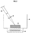
fig. 2] FIG. 2 is a schematic view showing another embodiment of the photocatalyst activation system of the present invention. - [
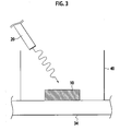
fig. 3] FIG. 3 is a schematic view showing still another embodiment of the photocatalyst activation system of the present invention. - [
fig. 4] FIG. 4 is a graph showing a temperature change of a butane conversion ratio in an example of the photocatalyst activation system of the present invention. - A description will be made below in detail of a photocatalyst activation system of the present invention. Note that, in this specification and claims, "%" added to values of concentrations, contents, loadings and the like represents a mass percentage unless otherwise specified.
- As described above, a first photocatalyst activation system according to an embodiment of the present invention is a system including: a catalyst; a light source; and a heat transfer device (heat transferring means). The light source supplies light to the catalyst, and the heat transfer device plays a role to transfer heat to the catalyst. Moreover, the catalyst includes a photocatalytic material containing cerium oxide. With such a configuration, catalytic activity is enhanced even in a temperature range as low as approximately 50°C.
- Note that, in the above-described catalyst, cerium oxide can be mixed or compounded with iron oxide and vanadium oxide. In this case, a usable wavelength range of light can be widened to the visible light range.
- Here, the light source is sufficient if the light source can supply the catalyst with light that allows activation of the photocatalytic material for use. The light source just needs to be one that applies any one of the ultraviolet light (wavelength range: 1 nm to 400 nm), the visible light (wavelength range: 380 nm to 780 nm) and the infrared light (wavelength range: 760 nm to 1000 µm), or applies light in which these are mixed. Typically, if the light to be applied is light having a wavelength equal to or more than energy corresponding to a band gap of the photocatalytic material for use, then electrons of a valence band in the photocatalytic material are excited to a conduction band therein, and holes are generated in the valence band, and accordingly, a photocatalytic reaction can be progressed. Note that, in the case where this light source is capable of applying the infrared light, not only infrared rays but also heat is transferred to the photocatalytic material. Accordingly, in this photocatalyst system, it is possible to omit the heat transfer device to be described later.
- The heat transfer device is not particularly limited as long as it can transfer the heat to the photocatalytic material for use. Moreover, a method of such heat transfer may be any of convection, radiation and heat conduction or an arbitrary combination thereof, and is not particularly limited. Specifically, a variety of heaters can be mentioned. However, the heat transfer device may be a lens (light condenser) capable of condensing the light (in particular, the visible light and the like) from the light source and heating the photocatalytic material. Note that, in this case, it is desirable to employ a configuration capable of condensing the light to the photocatalytic material with ease, in which either one or both of the lens and the light source are capable of being displaced.
- A shape and properties of the heat transfer device are not particularly limited, either. Besides such a thing as an electric heater, fluid such as liquid and gas and other mediums can also be used as the heat transfer device as long as they can transfer the heat to the photocatalytic material. For example, as the heat transfer device, there can also be used: a material that generates heat of reaction by an exothermic reaction such as an oxidation-reduction reaction; thermal fluid such as thermal gas and thermal liquid; a variety of mediums which generate heat by vibrations and a resonance phenomenon; a variety of mediums which generate heat by being irradiated with light; and the like.
- Note that, in the present invention, as such a heat transfer device, it is possible to apply exhaust heat from other engines and devices, for example, an internal combustion engine and a combustion engine. In particular, it is also possible to utilize exhaust heat from exhaust gas of an automobile, and exhaust heat from a boiler, a steel furnace or an incinerator. In this case, no problem occurs if such exhaust heat is in a pressurized atmosphere. Hence, the photocatalyst activation system of the present invention is usable for the engine of the automobile, the boiler, the steel furnace, and the incinerator.
- As described above, the photocatalyst system of the present invention is a system that can utilize the heat from the variety of light sources and is rich in practical utilities.
- Moreover, it is as described above that the infrared rays (infrared light) are usable as the heat transfer device. In this case, one light source in which an irradiation wavelength is variable may be used, or a different infrared light source that is not involved in the activation of the photocatalytic material may be installed and used. Note that the infrared light may be any of the far-infrared light (wavelength range: 25 µm to 1000 µm), the mid-infrared light (wavelength range: 2.5 µm to 25 µm), and the near-infrared light (wavelength range: 760 nm to 2.5 µm).
- Next, a second photocatalyst activation system according to the embodiment of the present invention includes a light source and a heat transfer device, which are similar to those of the above-described first photocatalyst activation system. However, the second photocatalyst activation system is different from the first photocatalyst activation system in using one selected arbitrarily from transition metal oxides other than cerium oxide.
- As such a transition metal oxide, there can be suitably used copper oxides (CuO, Cu2O), iron oxide (Fe2O3), vanadium oxide (V2O5), bismuth oxide (Bi2O3), titanium oxide (TiO2) or arbitrary mixtures thereof.
- These materials are useful since the materials can be activated by the visible light if predetermined heat energy (ambient temperature) can be imparted thereto. In particular, iron oxide and vanadium oxide are capable of responding to the visible light, and can widen the usable wavelength range of light to the visible light range. Note that the temperature required for activating these photocatalytic materials is typically 50°C or more.
- Moreover, the photocatalytic materials for use in the first and second photocatalyst activation systems of the present invention can further include transition metal compounds such as sulfides of the transition metals, nitrides of the transition metals, mixtures of these, or the like as long as these transition metal compounds exhibit the photocatalytic activity at the ordinary temperature. In such a way, the usable wavelength range of light can be widened to the visible light range.
- In the present invention, the catalyst may be composed only of the photocatalytic material as described as above, which is contained as an essential material. However, besides this, a promoter, for example, platinum (Pt), rhodium (Rh), palladium (Pd), ruthenium (Ru), silver (Ag), gold (Au), nickel (Ni), cobalt (Co), copper (Cu), iridium (Ir), or arbitrary mixtures of these can be contained in the catalyst. In such a way, a function to suppress a recombination of the separated electrons and holes can be emerged, and the activity can be increased by promoting the reaction between a reactant and the separated e- and h+.
- Note that a heating temperature for the catalyst by the above-described heat transfer device is not particularly limited as long as it is sufficient for enhancing the activity of the above-described catalyst in comparison with the time of room temperature (25°C); however, is preferably 50 to 300°C, more preferably 100 to 300°C.
-
FIG. 1 is a configuration view showing an embodiment of the photocatalyst activation system of the present invention. In this drawing, the photocatalyst activation system includes: acatalyst 10; alight source 20; and anelectric heater 30 as an example of the heat transfer device. Moreover, thecatalyst 10 is housed in areaction container 40 together with a treatment subject (not shown). A configuration is adopted, in which thereaction container 40 is mounted on theheater 30, and heat from theheater 30 is transferred to thecatalyst 10 with ease. - In accordance with the system shown in
FIG 1 , the treatment subject is housed in thereaction container 40, and thecatalyst 10 is activated, whereby various types of gas phase reactions and liquid phase reactions can be promoted. Specifically, by a similar system to that inFIG. 1 , the exhaust gas can be purified, reactivity of an organic synthesis reaction can be enhanced, and so on. - Moreover, in another embodiment of the photocatalyst activation system, which is shown in
FIG. 2 , as an example of the heat transfer device, aconvex lens 32 is shown, which can condense the light (in particular, the visible light) from the light source and can supply the condensed light to the photocatalytic material. Furthermore, in this system, either one or both of theconvex lens 32 and thelight source 20 are capable of being displaced, thus making it possible to condense the light into thecatalyst 10 with ease. - Furthermore, in still another embodiment of the photocatalyst activation system, which is shown in
FIG. 3 , as an example of the heat transfer device, anexhaust pipe 34 is shown, through which high-temperature exhaust gas flows. In this system, the above-described catalyst can be heated efficiently by heat transfer from the high-temperature exhaust gas discharged from an engine (not shown). Note that, inFIGS. 1 to 3 , thereaction container 40 is not an essential component, and it is not necessary to provide thereaction container 40 if the treatment target can contact thecatalyst 10. - A method for activating a photocatalyst according to the present invention can be performed by using the photocatalyst activation system as described above; however, the use of such a system is not essential. Specifically, in the case of activating the catalyst containing the photocatalytic material, it is sufficient if the light and the heat are supplied to the photocatalytic material, and a method and mean for supplying both of the light and the heat are not limited.
- The description will be made below more in detail of the present invention by examples and comparative examples; however, the present invention is not limited to these examples.
- Approximately 3 g of iron oxide (Fe2O3) was put onto a bottom portion of a quartz-made reaction tube with a hollow cylindrical shape and a capacity of approximately 200 ml, 20 vol% of oxygen/argon gas was supplied thereto, and a periphery of the reaction tube was heated at 400°C for one hour by a mantle heater, whereby pretreatment was performed.
- Thereafter, the reaction tube was cooled down to predetermined reaction temperatures (300°C, 250°C, 200°C, 150°C, 100°C, 50°C). Moreover, with regard to gas supply flow rates to the reaction tube, by a mass flow controller, a flow rate of butane was controlled at 5 ml/min, a flow rate of oxygen was controlled at 35 ml/min, and a flow rate of argon was controlled at 60 ml/min.
- Note that a 300W xenon lamp was used for the light source. Light applied from the xenon lamp was cooled by a water filter, and was condensed onto the photocatalyst through a condensing lens (made of BK7, f = 200 mm). An area of the applied light thus condensed had a diameter of approximately 10 mm.
- Gas generated by the photocatalytic reaction was analyzed by gas chromatography (TCD). Note that measurement values on and after 30 minutes after the light irradiation, from when the photocatalytic activity was stabilized, were employed as data.
- The above-described gasses were supplied at the above-described reaction temperatures, and thereafter, the generated gas was analyzed, and a conversion ratio from CO2 to butane was calculated. Then, while the conversion ratio was 25% at 50°C, the conversion ratio was greatly increased to 40% at 100 to 300°C.
- Similar operations to those of Example 1 were repeated except for changing the photocatalyst to cuprous oxide (Cu2O). The butane conversion ratio was 30% at 50°C, and 45% at 100 to 300°C.
- Similar operations to those of Example 1 were repeated except for changing the photocatalyst to cerium oxide (CeO2). The butane conversion ratio was 25% at 50°C, and 33% at 100 to 300°C.
- Similar operations to those of Example 1 were repeated except for changing the photocatalyst to vanadium oxide (V2O5). The butane conversion ratio was 25% at 50°C, and 33% at 100 to 300°C.
- Similar operations to those of Example 1 were repeated except for changing the photocatalyst to bismuth oxide (Bi2O). The butane conversion ratio was 6% at 50°C, and 8% at 100 to 300°C.
- Similar operations to those of Example 1 were repeated except for adding 3% of platinum to iron oxide and reacting both thereof with each other at 300°C. The butane conversion ratio was 50% at 300°C.
- Similar operations to those of Example 1 were repeated except for adding 1% of platinum to iron oxide and reacting both thereof with each other at 300°C. The butane conversion ratio was 48% at 300°C.
- Comparative example 1 was implemented under the same conditions as those in Example 1 except for setting the reaction temperature at 20°C. The butane conversion ratio was 5% at 50°C, and 7% at 100 to 300°C.
- Results of Example 1 are shown in Table 1 and
FIG. 4 .[Table 1] Catalyst temperature (°C) Butane conversion ratio (%) 50 25 100 35 150 39.5 200 39.5 250 39 300 38.5 - From Table 1 and
FIG 4 , it is obvious that, in accordance with the photocatalyst activation systems of the respective examples incorporated in the present invention, the activities of the materials in which the photocatalytic activities have been conventionally regarded to be lower than the photocatalytic activity of titanium oxide are enhanced significantly. Band gaps of these photocatalytic materials are narrower than the band gap of titanium oxide, and accordingly, the visible light range is also usable. From these facts, it is understood that the photocatalyst activation systems of these examples have high practical utilities and are thereby promising. - Specifically, also from these examples, it is obvious that, in accordance with the present invention, the photocatalytic activity can be enhanced to a large extent, and such a usable absorption wavelength range can be widened.
- A flat portion with a size of approximately 40×20 mm was provided in a part of a cylindrical reaction tube with an inner diameter of approximately 3 mm, which is made of Pyrex (registered trademark), in order to widen the area of the applied light. Onto this flat portion, 4.5 g of cerium oxide powder (mean particle diameter (D50): approximately 0.5 µm) was filled as the photocatalytic material, 20% O2/Ar was supplied thereto, and heating was performed therefor at 400°C for one hour, whereby pretreatment was performed. Note that the heating was performed in such a manner that a periphery of the reaction tube was surrounded by a ceramic heater of an open/close type, and a portion to be irradiated with the light is partially ensured.
- Thereafter, the reaction tube was cooled down to predetermined reaction temperatures (250°C, 200°C, 150°C, 100°C). Moreover, for the gas to be supplied to the reaction tube, 15% C4H10, 17% O2, 58% Ar, and 10% N2 were used. Furthermore, a flow rate of the gas to the reaction tube was controlled to be 200 ml/min by using the mass flow controller.
- The 300W xenon lamp was used for the light source. The light applied therefrom was cooled by the water filter, and was condensed onto the photocatalyst through the condensing lens (made of BK7, f = 200 mm). An area of the applied light thus condensed had a diameter of approximately 10 mm.
- Gas generated by the photocatalyst was analyzed by the gas chromatography (TDC). Measurements were performed on and after 30 minutes after the light irradiation, from when the photocatalytic activity was stabilized. Results were written as CO2 generation rates (µmol/min) on Table 2.
- Similar operations to those of Example 8 were repeated except for changing the photocatalytic material to 4.6 g of cerium oxide (mean particle diameter: approximately 8 µm), and an activation method of this example was attempted.
- Similar operations to those of Example 8 were repeated except for changing the photocatalytic material to 1.3 g of titanium oxide, and an activation method of this example was attempted.
- Similar operations to those of Example 8 were repeated except for changing the photocatalytic material to 2.6 g of iron oxide, and an activation method of this example was attempted.
- Similar operations to those of Example 8 were repeated except for changing the photocatalytic material to 2.3 g of vanadium oxide, and an activation method of this example was attempted.
- Similar operations to those of Example 8 were repeated except for changing the photocatalytic material to 3.5 g of a mixture of iron oxide and cerium oxide, and an activation method of this example was attempted. Note that the mixture of iron oxide and cerium oxide was prepared in such a manner that nitrates of these were mixed so as to be in a molar ratio of: Fe/Ce = 0.8/0.2, and were dissolved into 500 ml of water, then 28% of ammonia water was dropped thereinto so as obtain pH equal to 8, and an obtained liquid was stirred for 16 hours, was cleaned and filtered, and was thereafter fired at 400°C for five hours. Note that, as a result of measuring ultraviolet/visible light absorption spectra, a band gap of the photocatalytic material was able to be estimated at 760 nm, and it was also understood that the photocatalytic material was cable of absorbing the visible light.
- Similar operations to those of Example 13 were performed except for mixing the respective nitrates in the mixture of iron oxide and cerium oxide so as to be in the molar ratio of: Fe/Ce = 0.2/0.8.
- Similar operations to those of Example 8 were performed except for not performing the light irradiation, and an activation method of this example was attempted.
- Similar operations to those of Example 9 were performed except for not performing the light irradiation, and an activation method of this example was attempted.
- Similar operations to those of Example 10 were performed except for not performing the light irradiation.
- Similar operations to those of Example 11 were performed except for not performing the light irradiation.
- Similar operations to those of Example 12 were performed except for not performing the light irradiation.
- Similar operations to those of Example 13 were performed except for not performing the light irradiation.
- Similar operations to those of Example 14 were performed except for not performing the light irradiation.
- Results of Examples 8 to 14 and Comparative examples 2 to 8 are shown in Table 2. Note that "not measured" in Table 2 refers to that the measurement was discontinued in consideration for safety since the surface of the catalyst become red hot.
[Table 2] Catalyst Reaction temperature 100°C 150°C 200°C 250°C Example 8 CeO2 (mean particle diameter: approximately 0.5 µm) 4.5 7.4 Not measured Not measured Example 9 CeO2 (mean particle diameter: approximately 2.3 µm) 0 0.8 4.3 21.6 Example 10 TiO 20 4 7.5 20.5 Example 11 Fe2O3 0 0 2.5 17 Example 12 V2O5 0 0 2 8.6 Example 13 Fe0.8Ce0.2Ox 6 10 Not measured Not measured Example 14 Fe0.2Ce0.8Ox 5 8.1 Not measured Not measured Comparative example 2 CeO2 (mean particle diameter: approximately 0.5 µm) 0 4 6.5 13.5 Comparative example 3 CeO2 (mean particle diameter: approximately 2.3 µm) 0 0.5 1.6 10.7 Comparative example 4 TiO 20 0 1 10 Comparative example 5 Fe2O3 0 0 0 5 Comparative example 6 V2O5 0 0 0.8 5.2 Comparative example 7 Fe0.8Ce0.2Ox 0 1.5 3 6 Comparative example 8 Fe0.2Ce0.8Ox 0 1.2 2.8 5 - From Table 2, it is understood that cerium oxide is effective as the photocatalytic material in accordance with the activation method using the photocatalyst activation system, which is incorporated in the present invention. In particular, nanoparticulate cerium oxide with a small particle diameter and FeCeOx formed by mixing cerium oxide with iron oxide capable of responding to the visible light are promising. Specifically, from the above-described examples, it is obvious that the use of the photocatalytic material containing cerium oxide makes it possible to enhance the photocatalytic activity to a large extent and to respond to the visible light. Moreover, in accordance with the above-described examples, the use of the photocatalytic material containing the transition metal oxide other than cerium oxide also makes it possible to enhance the photocatalytic activity to a larger extent and to respond to the visible light.
- Note that cerium oxide or the transition metal oxide other than cerium oxide may be used singly as the photocatalytic material for use in the photocatalyst activation system of the present invention; however, cerium oxide and the transition metal oxide other than cerium oxide may be mixed and used. Also in this case, the photocatalytic activity can be enhanced to a large extent, and the usable absorption wavelength range can be widened.
- The entire contents of Japanese Patent Applications No.
2006-54573 (filed on: May 1, 2006 2007-37614 (filed on: February 19, 2007 - The description has been made above of the contents of the present invention along the embodiments and the examples; however, the present invention is not limited to the description of these, and for those skilled in the art, it is self-evident that a variety of modifications and improvements are possible.
- In accordance with the present invention, the configuration is adopted, in which the photocatalytic reaction is performed under the heating conditions. Accordingly, there can be provided the photocatalyst activation system and the method for activating a photocatalyst, which have the high practical utilities, are capable of widening the usable wavelength range of light, and are capable of enhancing the catalytic activity to a large extent.
Claims (12)
- A photocatalyst activation system, comprising:a catalyst which comprises a photocatalytic material containing cerium oxide;a light source which irradiates the catalyst with light; anda heat transfer device which transfers heat to the catalyst.
- A photocatalyst activation system, comprising:a catalyst which comprises a photocatalytic material containing at least one oxide selected from the group consisting of transition metal oxides other than cerium oxide;a light source which irradiates the catalyst with light; anda heat transfer device which transfers heat to the catalyst.
- The photocatalyst activation system according to claim 2, wherein the transition metal oxides are at least one oxide selected from the group consisting of iron oxide, copper oxide, vanadium oxide, bismuth oxide and titanium oxide.
- The photocatalyst activation system according to any one of claims 1 to 3, wherein the photocatalytic material comprises at least either one of transition metal sulfide and transition metal nitride.
- The photocatalyst activation system according to any one of claims 1 to 4, wherein the photocatalyst comprises at least one promoter selected from the group consisting of platinum, rhodium, palladium ruthenium, silver, gold, nickel, cobalt, copper and iridium.
- The photocatalyst activation system according to any one of claims 1 to 5, wherein the light applied from the light source has a wavelength equal to or more than energy corresponding to a band gap of the photocatalytic material.
- The photocatalyst activation system according to any one of claims 1 to 6, wherein the light applied from the light source is visible light.
- The photocatalyst activation system according to any one of claims 1 to 7, wherein the heat transfer device is a heater.
- The photocatalyst activation system according to any one of claims 1 to 8, wherein the heat transfer device is a light condenser of the light applied from the light source.
- The photocatalyst activation system according to any one of claims 1 to 9, wherein the heat transfer device has exhaust heat from other engine and/or device.
- The photocatalyst activation system according to any one of claims 1 to 10, wherein the light applied from the light source is an infrared ray, and the catalyst is heated by the infrared ray.
- A method for activating a photocatalyst, comprising:supplying light and heat to a photocatalyst which comprises a photocatalytic material containing cerium oxide.
Applications Claiming Priority (3)
| Application Number | Priority Date | Filing Date | Title |
|---|---|---|---|
| JP2006054573 | 2006-03-01 | ||
| JP2007037614A JP2007260667A (en) | 2006-03-01 | 2007-02-19 | Photocatalyst activation system and photocatalyst activation method |
| PCT/JP2007/053912 WO2007100039A1 (en) | 2006-03-01 | 2007-03-01 | Photocatalyst activation system and method for activating photocatalyst |
Publications (1)
| Publication Number | Publication Date |
|---|---|
| EP1994985A1 true EP1994985A1 (en) | 2008-11-26 |
Family
ID=38459138
Family Applications (1)
| Application Number | Title | Priority Date | Filing Date |
|---|---|---|---|
| EP07737592A Withdrawn EP1994985A1 (en) | 2006-03-01 | 2007-03-01 | Photocatalyst activation system and method for activating photocatalyst |
Country Status (4)
| Country | Link |
|---|---|
| US (1) | US20090020410A1 (en) |
| EP (1) | EP1994985A1 (en) |
| JP (1) | JP2007260667A (en) |
| WO (1) | WO2007100039A1 (en) |
Cited By (1)
| Publication number | Priority date | Publication date | Assignee | Title |
|---|---|---|---|---|
| WO2020173885A1 (en) * | 2019-02-25 | 2020-09-03 | The Queen's University Of Belfast | Method and apparatus for alkane oxidation |
Families Citing this family (6)
| Publication number | Priority date | Publication date | Assignee | Title |
|---|---|---|---|---|
| US7989385B2 (en) * | 2009-11-05 | 2011-08-02 | Siemens Energy, Inc. | Process of activation of a palladium catalyst system |
| JP5173080B2 (en) * | 2011-03-09 | 2013-03-27 | パナソニック株式会社 | How to reduce carbon dioxide |
| JP5323218B2 (en) * | 2012-02-15 | 2013-10-23 | 国立大学法人長岡技術科学大学 | Method for removing heavy metal ions from a liquid containing heavy metal ions |
| CN103464176A (en) * | 2013-09-27 | 2013-12-25 | 常州大学 | Preparation method of CeO2/AgBr composite microsphere visible light catalyst |
| CN104759287A (en) * | 2015-03-20 | 2015-07-08 | 上海应用技术学院 | Iron-doped cerium dioxide photocatalyst and preparation method thereof |
| US11491439B2 (en) | 2019-04-08 | 2022-11-08 | Saudi Arabian Oil Company | Method for reducing energy and water demands of scrubbing CO2 from CO2-lean waste gases |
Family Cites Families (32)
| Publication number | Priority date | Publication date | Assignee | Title |
|---|---|---|---|---|
| US3446754A (en) * | 1965-12-03 | 1969-05-27 | Nat Distillers Chem Corp | Catalyst activation |
| US3551147A (en) * | 1967-07-13 | 1970-12-29 | Itek Corp | Process for producing photographic images with photosensitive material |
| US4517063A (en) * | 1984-02-13 | 1985-05-14 | The Standard Oil Company | Photochemical reactor and method for carrying out photochemical reactions therein |
| DE3772220D1 (en) * | 1986-01-22 | 1991-09-26 | Hitachi Ltd | METHOD AND DEVICE FOR PHOTOELECTROCATALYTIC REDUCTION OF PRECIOUS METALS IN Nitric Acid Solution. |
| US5045288A (en) * | 1989-09-15 | 1991-09-03 | Arizona Board Of Regents, A Body Corporate Acting On Behalf Of Arizona State University | Gas-solid photocatalytic oxidation of environmental pollutants |
| KR100377606B1 (en) * | 1995-09-15 | 2003-08-25 | 로디아 쉬미 | Titanium dioxide-based photocatalyst coating substrate, and titanium dioxide-based organic dispersion |
| WO1997031703A1 (en) * | 1996-02-28 | 1997-09-04 | Hoya Corporation | Glass material for carrying a photocatalyst, filter device using the same and light irradiating method |
| JPH09262473A (en) | 1996-03-29 | 1997-10-07 | Mitsubishi Heavy Ind Ltd | Iron oxide photocatalyst and method for producing hydrogen using the same |
| DE19741498B4 (en) * | 1997-09-20 | 2008-07-03 | Evonik Degussa Gmbh | Production of a ceramic stainless steel mesh composite |
| CA2268469C (en) * | 1998-04-10 | 2004-03-23 | University Of Central Florida | Apparatus and method for photocatalytic and thermocatalytic pollution control |
| US6267940B1 (en) * | 1999-08-10 | 2001-07-31 | Electric Power Research Institute, Inc. | Method for reducing NOx with an activated catalyst |
| US6685891B2 (en) * | 1999-09-27 | 2004-02-03 | Chelsea Group Ltd. | Apparatus and method for purifying air |
| DE10049595A1 (en) * | 1999-10-13 | 2001-05-23 | Sekretaer Der Agentur Der Ind | Cleaning assembly, for incinerator exhaust gas emissions, is cylinder structure with photo catalyst balls in contact with the gas flow which are excited by light to destroy hazardous matter in gas |
| JP2001259436A (en) | 2000-03-17 | 2001-09-25 | Kawasaki Steel Corp | Fe2O3 photocatalyst component, photocatalyst and method for removing nitrogen oxides in air |
| JP2002028496A (en) * | 2000-07-14 | 2002-01-29 | Nippon Zeon Co Ltd | Photocatalyst and method of using the same |
| US6585863B2 (en) * | 2000-08-08 | 2003-07-01 | Procter & Gamble Company | Photocatalytic degradation of organic compounds |
| JP4107792B2 (en) * | 2000-08-28 | 2008-06-25 | 独立行政法人科学技術振興機構 | Photocatalyst composed of metal oxynitride having visible light response |
| JP4107807B2 (en) * | 2001-02-07 | 2008-06-25 | 独立行政法人科学技術振興機構 | Oxysulfide photocatalyst for visible light decomposition of water |
| JP4064065B2 (en) * | 2001-02-07 | 2008-03-19 | 独立行政法人科学技術振興機構 | Photocatalyst for visible light decomposition of water |
| US6878277B2 (en) * | 2001-06-20 | 2005-04-12 | Hoya Candeo Optronics Corporation | Photocatalytic filter, photocatalytic filter device and method for manufacturing photocatalytic filter |
| JP4048775B2 (en) * | 2001-12-26 | 2008-02-20 | 住友化学株式会社 | Titanium oxide, photocatalyst body and photocatalyst body coating agent using the same |
| JP2003210998A (en) * | 2002-01-25 | 2003-07-29 | Japan Science & Technology Corp | Photocatalytic system |
| JP4142303B2 (en) * | 2002-02-14 | 2008-09-03 | 独立行政法人科学技術振興機構 | Photocatalyst containing titanium fluoronitride for water decomposition by irradiation with visible light and method for producing the same |
| JP2004089953A (en) | 2002-09-03 | 2004-03-25 | National Institute Of Advanced Industrial & Technology | Continuous decomposition and removal method of organic substances contained in gas |
| JP4070624B2 (en) | 2003-01-31 | 2008-04-02 | 独立行政法人科学技術振興機構 | Method for improving photocatalytic activity comprising metal nitride and metal oxynitride having visible light responsiveness |
| JP3944094B2 (en) * | 2003-02-24 | 2007-07-11 | 株式会社サンデコール | Photocatalyst production method, photocatalyst and gas purification device |
| JP2005074392A (en) | 2003-09-03 | 2005-03-24 | Ebara Corp | Method and apparatus for cleaning gas containing hydrocarbon by means of photocatalyst and cleaning space |
| JP4563108B2 (en) | 2004-08-10 | 2010-10-13 | フォスター電機株式会社 | Method for manufacturing diaphragm for electroacoustic transducer, diaphragm and manufacturing apparatus therefor |
| CN100425330C (en) * | 2005-03-31 | 2008-10-15 | 鸿富锦精密工业(深圳)有限公司 | Photocatalysis intensifier |
| JP2006297300A (en) * | 2005-04-21 | 2006-11-02 | Nissan Motor Co Ltd | Semiconductor photoelectrode, manufacturing method thereof, and light energy conversion device |
| JP2007037614A (en) | 2005-08-01 | 2007-02-15 | Matsushita Electric Ind Co Ltd | Oxygen enricher |
| WO2007022462A2 (en) * | 2005-08-19 | 2007-02-22 | North Carolina State University | Solar photocatalysis using transition-metal oxides combining d0 and d6 electron configurations |
-
2007
- 2007-02-19 JP JP2007037614A patent/JP2007260667A/en not_active Withdrawn
- 2007-03-01 US US12/279,381 patent/US20090020410A1/en not_active Abandoned
- 2007-03-01 WO PCT/JP2007/053912 patent/WO2007100039A1/en not_active Ceased
- 2007-03-01 EP EP07737592A patent/EP1994985A1/en not_active Withdrawn
Non-Patent Citations (1)
| Title |
|---|
| See references of WO2007100039A1 * |
Cited By (2)
| Publication number | Priority date | Publication date | Assignee | Title |
|---|---|---|---|---|
| WO2020173885A1 (en) * | 2019-02-25 | 2020-09-03 | The Queen's University Of Belfast | Method and apparatus for alkane oxidation |
| CN113784778A (en) * | 2019-02-25 | 2021-12-10 | 英国贝尔法斯特女王大学 | Method and apparatus for alkane oxidation |
Also Published As
| Publication number | Publication date |
|---|---|
| WO2007100039A1 (en) | 2007-09-07 |
| JP2007260667A (en) | 2007-10-11 |
| US20090020410A1 (en) | 2009-01-22 |
Similar Documents
| Publication | Publication Date | Title |
|---|---|---|
| Murugan et al. | Nature of Manganese Species in Ce1-x Mn x O2-δ Solid Solutions Synthesized by the Solution Combustion Route | |
| Chary et al. | Characterization and reactivity of copper oxide catalysts supported on TiO2− ZrO2 | |
| US20090020410A1 (en) | Photocatalyst activation system and method for activating photocatalyst | |
| Falcón et al. | SrFeO3-δ perovskite oxides: chemical features and performance for methane combustion | |
| EP1870158B1 (en) | Transition metal-substituted hydrotalcite catalyst for removing nitrogen oxides from the exhaust gas of diesel engine by storage-reduction. | |
| US10478805B2 (en) | Method for producing ammonia combustion catalyst and method for utilizing heat generated by ammonia catalyst combustion | |
| Azambre et al. | Probing the Surface of Ceria− Zirconia Catalysts Using NO x Adsorption/Desorption: A First Step Toward the Investigation of Crystallite Heterogeneity | |
| JP5422320B2 (en) | Catalyst for decomposing volatile organic compounds and method for decomposing volatile organic compounds | |
| Gao et al. | Catalytic activity for methane combustion of the perovskite-type La1− xSrxCoO3− δ oxide prepared by the urea decomposition method | |
| CA2506099A1 (en) | Application of conductive adsorbents, activated carbon granules and carbon fibers as substrates in catalysis | |
| JP7481738B2 (en) | Platinum-supported molybdenum oxide catalyst and method for producing carbon monoxide and methanol using said catalyst | |
| Zhang et al. | Unraveling the promotional effect of Co on the Pd/TiO2 catalyst for H2-SCR of NOx in the presence of oxygen | |
| Tang et al. | Direct Z-scheme La1-x Ce x MnO3 catalyst for photothermal degradation of toluene | |
| JP2001239161A (en) | Low temperature harmful gas purification catalyst | |
| Agbovhimen Elimian et al. | Harnessing solar energy towards synergistic photothermal catalytic oxidation of volatile organic compounds | |
| Tang et al. | Mesoporous double-perovskite LaAMnNiO6 (A= La, Pr, Sm) photothermal synergistic degradation of gaseous toluene | |
| Yang et al. | Solvothermal fabrication of activated semi-coke supported TiO2-rGO nanocomposite photocatalysts and application for NO removal under visible light | |
| CN107511160A (en) | A kind of MOX/g C3N4@SiO2The preparation method and applications of catalyst | |
| Dativo et al. | CO2 conversion by solar photothermo co-catalysis on montmorillonite-based catalysts | |
| EP1262224A1 (en) | Process for the catalytic decomposition of nitrous oxide (N2O) | |
| KR102012894B1 (en) | Manganese-Ceria-Tungsten-titania catalyst for removing NOx and preparing method of thereof | |
| KR20180055027A (en) | Manganese-Ceria-Tungsten-titania catalyst for removing NOx and preparing method of thereof | |
| Bera et al. | Solution combustion synthesis, characterization, and catalytic properties of oxide materials | |
| WO2004096436A1 (en) | Catalyst material comprising transition metal oxide | |
| US20090035711A1 (en) | Photocatalytic ignition system |
Legal Events
| Date | Code | Title | Description |
|---|---|---|---|
| PUAI | Public reference made under article 153(3) epc to a published international application that has entered the european phase |
Free format text: ORIGINAL CODE: 0009012 |
|
| 17P | Request for examination filed |
Effective date: 20080813 |
|
| AK | Designated contracting states |
Kind code of ref document: A1 Designated state(s): DE FR GB |
|
| RBV | Designated contracting states (corrected) |
Designated state(s): DE FR GB |
|
| STAA | Information on the status of an ep patent application or granted ep patent |
Free format text: STATUS: THE APPLICATION HAS BEEN WITHDRAWN |
|
| 18W | Application withdrawn |
Effective date: 20110218 |