EP1994856A1 - A worktop of a household aplliance and method of manufacturing a worktop of a household appliance - Google Patents
A worktop of a household aplliance and method of manufacturing a worktop of a household appliance Download PDFInfo
- Publication number
- EP1994856A1 EP1994856A1 EP07108570A EP07108570A EP1994856A1 EP 1994856 A1 EP1994856 A1 EP 1994856A1 EP 07108570 A EP07108570 A EP 07108570A EP 07108570 A EP07108570 A EP 07108570A EP 1994856 A1 EP1994856 A1 EP 1994856A1
- Authority
- EP
- European Patent Office
- Prior art keywords
- frame
- panel
- worktop
- fastening elements
- film
- Prior art date
- Legal status (The legal status is an assumption and is not a legal conclusion. Google has not performed a legal analysis and makes no representation as to the accuracy of the status listed.)
- Withdrawn
Links
Images


Classifications
-
- A—HUMAN NECESSITIES
- A47—FURNITURE; DOMESTIC ARTICLES OR APPLIANCES; COFFEE MILLS; SPICE MILLS; SUCTION CLEANERS IN GENERAL
- A47B—TABLES; DESKS; OFFICE FURNITURE; CABINETS; DRAWERS; GENERAL DETAILS OF FURNITURE
- A47B96/00—Details of cabinets, racks or shelf units not covered by a single one of groups A47B43/00 - A47B95/00; General details of furniture
- A47B96/18—Tops specially designed for working on
Definitions
- the present invention relates to a worktop of a household appliance, in particular of a dishwasher, a washing machine or a drying machine, and to a method of manufacturing a worktop of a household appliance.
- washing machines laundry washing machines and dishwashing machines
- drying machines have a machine structure or body (usually made of metal sheets) which houses internal components and is open at the top; the top of the machine structure is normally closed by a cover plate, usually formed by a wooden panel surrounded by a plastic frame, which also define a worktop for the user and therefore commonly named "worktop".
- the worktop is usually connected to the machine structure by fastening elements which engage respective seats formed in the machine structure.
- the frame is manufactured in the form of an open ring which is integrally provided with the fastening elements; the fastening elements do not hamper the insertion of the panel since the open ring of the frame may be easily deformed to be positioned around the panel edge; after positioning around the peripheral edge of the panel, the open-ring frame is closed by a joint; the frame is then firmly connected to the panel by metal clamps.
- This kind of worktop is relatively easy and cheap to be realized, but has the drawback that the frame has a cut and a joint in the visible part of the worktop, which is not appreciated by users and customers.
- the plastic frame consists of a monolithic continuous ring-shaped body, which is glued to the panel; the fastening elements for connection to the machine structure are glued directly to the bottom surface of the panel.
- this solution is quite expensive (mainly because glue is needed) and the assembly process is also relatively complicated, since it is necessary to correctly position the fastening elements on the panel.
- a worktop of a household appliance in particular of a dishwasher, a washing machine or a drying machine, fittable to an appliance structure and comprising a panel, having a peripheral edge, and a frame, coupled to the peripheral edge of the panel and consisting of a monolithic ring body defining a continuous closed loop; the worktop being characterized in that the monolithic ring body of the frame is integrally provided with fastening elements clamping the panel and connected to the frame by respective plastic film-hinges.
- a method of manufacturing a worktop of a household appliance in particular of a dishwasher, a washing machine or a drying machine, the worktop comprising a panel, having a peripheral edge, and a frame, coupled to the peripheral edge of the panel and consisting of a monolithic ring body defining a continuous closed loop; the method comprising the steps of:
- the worktop according to the invention has therefore a fully satisfactory aesthetical appearance, since the frame consists of one single-piece closed ring which does not has any cut or joint; at the same time, the worktop is realized by an easy and low-cost manufacturing method.
- number 1 indicates an electric household appliance of any type, for example a dishwasher; nevertheless, the following description also applies to any other type of appliance, such as a washing machine, drying machine, refrigerator, freezer, oven, etc.
- Appliance 1 comprises an appliance structure 2, generally known and therefore not described nor shown in details for the sake of simplicity, and a top cover plate defining a worktop 3, which is fittable to structure 2 by connection members 4.
- Structure 2 comprises a substantially prismatic casing 5, which houses internal functional components (not shown) of appliance 1; a top end 6 of structure 2 is open to enable assembly of the functional components inside; worktop 3 is so formed as to mate with top end 6 of structure 2 and provides for closing top end 6 while at the same time forming a supporting surface for the user.
- Connection members 4 comprise for example connection blocks 7 carried by worktop 3 and engaging respective connection seats 8 formed in structure 2, for example in two cross bars 9 at top end 6 of structure 2.
- Worktop 3 comprises a panel 10 delimited by an outer peripheral edge 11, for example a substantially flat panel having a substantially quadrangular (e.g. square or rectangular) shape; and a frame 12, coupled to the whole profile of peripheral edge 11.
- Panel 10 has a top surface 13 (intended to be visible in use) and an opposite bottom surface 14 facing structure 2.
- Panel 10 is made of wood and/or plastic layers, or other suitable materials; frame 12 is preferably made of a plastic material.
- frame 12 consists of a monolithic ring body 15 defining a continuous closed loop.
- Frame 12 has a substantially quadrangular shape (possibly with rounded corners and/or curved sides) and comprises a base wall 16, substantially parallel to panel 10 and having a front surface 17 and a rear surface 18; and a lateral wall 19, projecting from an outer perimetral edge of rear surface 18 and substantially perpendicular to base wall 16.
- Base wall 16 delimits a central opening 21; front surface 17 is intended to be visible in use, while rear surface 18 defines a bottom shoulder 23 that contacts top surface 13 of panel 10.
- Frame 12 is internally provided with an inner perimetral seat 25 matching the profile of peripheral edge 11 of panel 10 and housing peripheral edge 11.
- seat 25 has a non-symmetrical substantially C-shaped cross-section and contacts top and bottom surfaces 13, 14 of panel 10; seat 25 is delimited by shoulder 23, that contacts top surface 13 of panel 10, and by an inner wall 26, substantially parallel to shoulder 23 and contacting bottom surface 14 of panel 10.
- Frame 12 is integrally provided with a number of fastening elements 27, 28 clamping panel 10 and connected to frame 12 by respective plastic film-hinges 29.
- Fastening elements 27, 28 project from an inner perimetral edge 30 of inner wall 26 to face shoulder 23 and are spaced apart from one another along inner perimetral edge 30; fastening elements 27, 28 are positioned on at least two opposite sides of frame 12.
- frame 12 is provided with main fastening elements 27, intended to both clamp panel 10 and connect frame 12 to structure 2, and auxiliary fastening elements 28 intended only to clamp panel 10.
- each fastening element 27, 28 comprises a substantially flat base portion 32 contacting bottom surface 14 of panel 10 and projecting from inner wall 26; base portions 32 are connected integrally to inner wall 26 by flexile portions 33 which define film-hinges 29.
- flexile portions 33 consist of narrowed cross-section strap portions, having a thickness less than the thickness of both base portions 32 and inner wall 26.
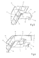
- Auxiliary fastening elements 28 ( Figure 5 ) are provided with stiffening ribs 34 projecting from base portions 32 opposite to panel 10.
- Each main fastening element 27 ( Figure 6 ) comprise instead a base portion 32 and a connection portion 35, which is integrally formed with base portion 32 and project from base portion 32 opposite to panel 10; connection portions 35 are provided with connection blocks 7 which are fitted to respective connection seats 8 of structure 2 and locked in seats 8 in known manner (e.g. by means of screws, not shown).
- Panel 10 is housed in perimetral seat 25 and clamped between shoulder 23 and fastening elements 27, 28.
- Fastening elements 27, 28 are coupled to panel 10 by fixing elements 36 (only some of which shown in Figures 1 and 5-6 ) engaging base portions 32 and panel 10.
- fixing elements 36 are metallic clamps passing through base portions 32 and engaging panel 10.
- a film 37 of sealing material ( Figure 1 ), e.g. a film of vaseline, is interposed between peripheral edge 11 of panel 10 and frame 12.
- the manufacturing method of worktop 3 is as follows.
- Frame 12 is manufactured by moulding, in particular injection moulding, a suitable plastic material (preferably a thermoplastic material); the whole frame 12, consisting of body 15 integrally provided with fastening elements 27, 28, is moulded in one moulding step.
- a suitable plastic material preferably a thermoplastic material
- Film 37 of sealing material e.g. vaseline, is applied onto peripheral edge 11 of panel 10.
- fastening elements 27, 28 are rotated around respective film-hinges 29 so as to move fastening elements 27, 28 away from shoulder 23; then panel 10 is inserted in frame 12 and specifically in seat 25 and against shoulder 23; film 37 of sealing material remain interposed between peripheral edge 11 of panel 10 and frame 12; fastening elements 27, 28 are then counter-rotated around film-hinges 29 towards shoulder 23, so as to clamp panel 10 between fastening elements 27, 28 and shoulder 23.
- fastening element 27, 28 are firmly and permanently connected to panel 10 by fixing elements 36, i.e. by penetrating metallic clamps through base portions 32 of fastening elements 27, 28 and in panel 10.
Landscapes
- Main Body Construction Of Washing Machines And Laundry Dryers (AREA)
Abstract
Description
- The present invention relates to a worktop of a household appliance, in particular of a dishwasher, a washing machine or a drying machine, and to a method of manufacturing a worktop of a household appliance.
- It is known that some kinds of electric household appliances, for example washing machines (laundry washing machines and dishwashing machines) and drying machines, have a machine structure or body (usually made of metal sheets) which houses internal components and is open at the top; the top of the machine structure is normally closed by a cover plate, usually formed by a wooden panel surrounded by a plastic frame, which also define a worktop for the user and therefore commonly named "worktop". The worktop is usually connected to the machine structure by fastening elements which engage respective seats formed in the machine structure.
- According to a known solution, the frame is manufactured in the form of an open ring which is integrally provided with the fastening elements; the fastening elements do not hamper the insertion of the panel since the open ring of the frame may be easily deformed to be positioned around the panel edge; after positioning around the peripheral edge of the panel, the open-ring frame is closed by a joint; the frame is then firmly connected to the panel by metal clamps. This kind of worktop is relatively easy and cheap to be realized, but has the drawback that the frame has a cut and a joint in the visible part of the worktop, which is not appreciated by users and customers.
- According to another known solution, the plastic frame consists of a monolithic continuous ring-shaped body, which is glued to the panel; the fastening elements for connection to the machine structure are glued directly to the bottom surface of the panel. In this way, the aesthetical appearance of the worktop is fully satisfactory, because the visible part of the worktop does not have joints; however, this solution is quite expensive (mainly because glue is needed) and the assembly process is also relatively complicated, since it is necessary to correctly position the fastening elements on the panel.
- It is an object of the present invention to provide a worktop of a household appliance, in particular of a dishwasher, a washing machine or a drying machine, and a method of manufacturing a worktop of a household appliance designed to eliminate the aforementioned drawbacks.
- In particular, it is an object of the invention to provide a low-cost and easy-to-manufacture worktop which is also fully satisfactory and effective from both an aesthetical point of view and a functional point of view.
- According to the present invention, there is provided a worktop of a household appliance, in particular of a dishwasher, a washing machine or a drying machine, fittable to an appliance structure and comprising a panel, having a peripheral edge, and a frame, coupled to the peripheral edge of the panel and consisting of a monolithic ring body defining a continuous closed loop; the worktop being characterized in that the monolithic ring body of the frame is integrally provided with fastening elements clamping the panel and connected to the frame by respective plastic film-hinges.
- According to the invention, there is also provided a method of manufacturing a worktop of a household appliance, in particular of a dishwasher, a washing machine or a drying machine, the worktop comprising a panel, having a peripheral edge, and a frame, coupled to the peripheral edge of the panel and consisting of a monolithic ring body defining a continuous closed loop; the method comprising the steps of:
- providing the frame integrally with fastening elements projecting from an inner perimetral edge of the frame to face a bottom shoulder of the frame and connected to the frame by respective film-hinges;
- rotating the fastening elements around the film-hinges so as to move the fastening elements away from the shoulder;
- inserting the panel in the frame and against the shoulder;
- counter-rotating the fastening elements around the film-hinges towards the shoulder, so as to clamp the panel between the fastening elements and the shoulder.
- The worktop according to the invention has therefore a fully satisfactory aesthetical appearance, since the frame consists of one single-piece closed ring which does not has any cut or joint; at the same time, the worktop is realized by an easy and low-cost manufacturing method.
- Non-limiting embodiments of the present invention will be described by way of example with reference to the accompanying drawings, in which:
-
Figure 1 is a schematic perspective exploded view of an electric household appliance featuring a worktop in accordance with the present invention; -
Figures 2 to 4 are partial larger-scale underside views of respective details of the worktop ofFigure 1 , with parts not-shown for the sake of clarity; -
Figure 5-6 are larger-scale view of further details of the worktop ofFigure 1 . - With reference to
Figure 1 ,number 1 indicates an electric household appliance of any type, for example a dishwasher; nevertheless, the following description also applies to any other type of appliance, such as a washing machine, drying machine, refrigerator, freezer, oven, etc. -
Appliance 1 comprises anappliance structure 2, generally known and therefore not described nor shown in details for the sake of simplicity, and a top cover plate defining a worktop 3, which is fittable to structure 2 byconnection members 4. -
Structure 2 comprises a substantiallyprismatic casing 5, which houses internal functional components (not shown) ofappliance 1; atop end 6 ofstructure 2 is open to enable assembly of the functional components inside; worktop 3 is so formed as to mate withtop end 6 ofstructure 2 and provides for closingtop end 6 while at the same time forming a supporting surface for the user.Connection members 4 comprise forexample connection blocks 7 carried by worktop 3 and engagingrespective connection seats 8 formed instructure 2, for example in twocross bars 9 attop end 6 ofstructure 2. - Worktop 3 comprises a
panel 10 delimited by an outerperipheral edge 11, for example a substantially flat panel having a substantially quadrangular (e.g. square or rectangular) shape; and aframe 12, coupled to the whole profile ofperipheral edge 11.Panel 10 has a top surface 13 (intended to be visible in use) and anopposite bottom surface 14 facingstructure 2. -
Panel 10 is made of wood and/or plastic layers, or other suitable materials;frame 12 is preferably made of a plastic material. - With reference also to
Figures 2 to 4 ,frame 12 consists of amonolithic ring body 15 defining a continuous closed loop.Frame 12 has a substantially quadrangular shape (possibly with rounded corners and/or curved sides) and comprises abase wall 16, substantially parallel topanel 10 and having afront surface 17 and arear surface 18; and alateral wall 19, projecting from an outer perimetral edge ofrear surface 18 and substantially perpendicular tobase wall 16. -
Base wall 16 delimits acentral opening 21;front surface 17 is intended to be visible in use, whilerear surface 18 defines abottom shoulder 23 that contactstop surface 13 ofpanel 10. -
Frame 12 is internally provided with an innerperimetral seat 25 matching the profile ofperipheral edge 11 ofpanel 10 and housingperipheral edge 11. - According to the preferred but non-limitative embodiment shown in the figures,
seat 25 has a non-symmetrical substantially C-shaped cross-section and contacts top andbottom surfaces panel 10;seat 25 is delimited byshoulder 23, that contactstop surface 13 ofpanel 10, and by aninner wall 26, substantially parallel toshoulder 23 and contactingbottom surface 14 ofpanel 10. -
Frame 12 is integrally provided with a number offastening elements clamping panel 10 and connected toframe 12 by respective plastic film-hinges 29. - Fastening
elements perimetral edge 30 ofinner wall 26 to faceshoulder 23 and are spaced apart from one another along innerperimetral edge 30;fastening elements frame 12. - In particular,
frame 12 is provided withmain fastening elements 27, intended to bothclamp panel 10 and connectframe 12 tostructure 2, andauxiliary fastening elements 28 intended only toclamp panel 10. - In the embodiment shown in the figures, there are provided two couples of
main fastening elements 27, positioned on opposite sides offrame 12, and a number ofauxiliary fastening elements 28 preferably positioned on all the sides offrame 12. - As it is better shown in
Figures 5, 6 , eachfastening element flat base portion 32 contactingbottom surface 14 ofpanel 10 and projecting frominner wall 26;base portions 32 are connected integrally toinner wall 26 byflexile portions 33 which define film-hinges 29. In the non limiting embodiment shown,flexile portions 33 consist of narrowed cross-section strap portions, having a thickness less than the thickness of bothbase portions 32 andinner wall 26. - Auxiliary fastening elements 28 (
Figure 5 ) are provided withstiffening ribs 34 projecting frombase portions 32 opposite topanel 10. - Each main fastening element 27 (
Figure 6 ) comprise instead abase portion 32 and aconnection portion 35, which is integrally formed withbase portion 32 and project frombase portion 32 opposite topanel 10;connection portions 35 are provided withconnection blocks 7 which are fitted torespective connection seats 8 ofstructure 2 and locked inseats 8 in known manner (e.g. by means of screws, not shown). -
Panel 10 is housed inperimetral seat 25 and clamped betweenshoulder 23 andfastening elements elements panel 10 by fixing elements 36 (only some of which shown inFigures 1 and5-6 )engaging base portions 32 andpanel 10. Preferably,fixing elements 36 are metallic clamps passing throughbase portions 32 andengaging panel 10. - A
film 37 of sealing material (Figure 1 ), e.g. a film of vaseline, is interposed betweenperipheral edge 11 ofpanel 10 andframe 12. - The manufacturing method of worktop 3 is as follows.
-
Frame 12 is manufactured by moulding, in particular injection moulding, a suitable plastic material (preferably a thermoplastic material); thewhole frame 12, consisting ofbody 15 integrally provided withfastening elements -
Film 37 of sealing material, e.g. vaseline, is applied ontoperipheral edge 11 ofpanel 10. - In order to allow
panel 10 to be inserted inframe 12,fastening elements hinges 29 so as to movefastening elements shoulder 23; thenpanel 10 is inserted inframe 12 and specifically inseat 25 and againstshoulder 23;film 37 of sealing material remain interposed betweenperipheral edge 11 ofpanel 10 andframe 12;fastening elements hinges 29 towardsshoulder 23, so as toclamp panel 10 betweenfastening elements shoulder 23. - Finally,
fastening element panel 10 byfixing elements 36, i.e. by penetrating metallic clamps throughbase portions 32 offastening elements panel 10. - Worktop 3 is then ready to be assembled to
structure 2, by means ofconnection members 4. - Clearly, further changes may be made to the worktop and the manufacturing method as described and illustrated herein without, however, departing from the scope of the present invention as defined by the enclosed Claims.
Claims (17)
- A worktop (3) of a household appliance (1), in particular of a dishwasher, a washing machine or a drying machine, fittable to an appliance structure (2) and comprising a panel (10), having a peripheral edge (11), and a frame (12), coupled to the peripheral edge of the panel and consisting of a monolithic ring body (15) defining a continuous closed loop; the worktop being characterized in that the monolithic ring body (15) of the frame (12) is integrally provided with fastening elements (27, 28) clamping the panel (10) and connected to the frame (12) by respective plastic film-hinges (29).
- A worktop as claimed in Claim 1, characterized in that said film-hinges (29) are defined by flexile portions (33) which connect integrally the fastening elements (27, 28) to the frame (12).
- A worktop as claimed in Claim 1 or 2, characterized in that said film-hinges (29) are defined by narrowed cross-section strap portions (33) which connect an inner wall (26) of the frame (12) to respective base portions (32) of the fastening elements (27, 28) projecting from said inner wall (26).
- A worktop as claimed in one of the foregoing Claims, characterized in that the monolithic ring body (15) of the frame (12) is made of a plastic material.
- A worktop as claimed in one of the foregoing Claims, characterized in that the frame (12) has a bottom shoulder (23) contacting a top surface (13) of the panel (10), and the fastening elements (27, 28) project from an inner perimetral edge (30) of the frame (12) to face the shoulder (23); the panel (10) being clamped between the shoulder (23) and the fastening elements (27, 28).
- A worktop as claimed in one of the foregoing Claims, characterized in that each fastening element (27, 28) comprises a substantially flat base portion (32) contacting a bottom surface (14) of the panel (10); the fastening elements (27, 28) being coupled to the panel (10) by fixing elements (36) engaging said base portions (32) and the panel (10).
- A worktop as claimed in Claim 6, characterized in that said fixing elements (36) are metallic clamps passing through the base portions (32) and engaging the panel (10).
- A worktop as claimed in one of the foregoing Claims, characterized in that a number of first fastening elements (27) comprise respective connection portions (35) integrally formed with said first fastening elements (27) and provided with connection blocks (7) connecting the frame (12) to the appliance structure (2).
- A worktop as claimed in one of the foregoing Claims, characterized in that a film (37) of sealing material, e.g. a film of vaseline, is interposed between the peripheral edge (11) of the panel (10) and the frame (12).
- A household appliance (1), in particular a dishwasher, a washing machine or a drying machine, characterized by comprising a worktop (3) according to one of Claims 1 to 9.
- A method of manufacturing a worktop (3) of a household appliance (1), in particular of a dishwasher, a washing machine or a drying machine, the worktop (3) comprising a panel (10), having a peripheral edge (11), and a frame (12), coupled to the peripheral edge of the panel and consisting of a monolithic ring body (15) defining a continuous closed loop; the method comprising the steps of:- providing the frame (12) integrally with fastening elements (27, 28) projecting from an inner perimetral edge (30) of the frame (12) to face a bottom shoulder (23) of the frame and connected to the frame by respective film-hinges (29);- rotating the fastening elements (27, 28) around the film-hinges (29) so as to move the fastening elements away from the shoulder (23);- inserting the panel (10) in the frame (12) and against the shoulder (23);- counter-rotating the fastening elements (27, 28) around the film-hinges (29) towards the shoulder (23), so as to clamp the panel between the fastening elements and the shoulder.
- A method as claimed in Claim 11, wherein the fastening elements (27, 28) are integrally formed together with the frame (12) in a step of manufacturing the frame.
- A method as claimed in Claim 12, wherein the frame (12) is made of a plastic material and the manufacturing step is a moulding step.
- A method as claimed in one of Claims 11 to 13, further comprising, after clamping the panel (10) between the fastening elements (27, 28) and the shoulder (23), a step of connecting the fastening element (27, 28) to the panel (10) by fixing elements (36) engaging the fastening elements and the panel.
- A method as claimed in Claim 14, wherein the fastening element (27, 28) are connected to the panel (10) by metallic clamps.
- A method as claimed in one of Claims 11 to 15, comprising, before the step of inserting the panel (10) in the frame (12), a step of applying a film (37) of sealing material, e.g. a film of vaseline, onto the peripheral edge (11) of the panel, so as the film of sealing material is interposed between the peripheral edge of the panel and the frame.
- A method as claimed in one of Claims 11 to 16, wherein in the step of manufacturing the frame (12), a number of first fastening elements (27) are realized with respective connection portions (35) integrally formed with the first fastening elements and having connection blocks for connecting the frame to the appliance structure (2).
Priority Applications (1)
| Application Number | Priority Date | Filing Date | Title |
|---|---|---|---|
| EP07108570A EP1994856A1 (en) | 2007-05-21 | 2007-05-21 | A worktop of a household aplliance and method of manufacturing a worktop of a household appliance |
Applications Claiming Priority (1)
| Application Number | Priority Date | Filing Date | Title |
|---|---|---|---|
| EP07108570A EP1994856A1 (en) | 2007-05-21 | 2007-05-21 | A worktop of a household aplliance and method of manufacturing a worktop of a household appliance |
Publications (1)
| Publication Number | Publication Date |
|---|---|
| EP1994856A1 true EP1994856A1 (en) | 2008-11-26 |
Family
ID=38998518
Family Applications (1)
| Application Number | Title | Priority Date | Filing Date |
|---|---|---|---|
| EP07108570A Withdrawn EP1994856A1 (en) | 2007-05-21 | 2007-05-21 | A worktop of a household aplliance and method of manufacturing a worktop of a household appliance |
Country Status (1)
| Country | Link |
|---|---|
| EP (1) | EP1994856A1 (en) |
Cited By (3)
| Publication number | Priority date | Publication date | Assignee | Title |
|---|---|---|---|---|
| WO2014101960A1 (en) * | 2012-12-28 | 2014-07-03 | Arcelik Anonim Sirketi | A cooking appliance comprising a handling means |
| US8978227B2 (en) | 2008-12-19 | 2015-03-17 | Bsh Bosch Und Siemens Hausgeraete Gmbh | Dishwasher |
| RU2571952C1 (en) * | 2014-10-23 | 2015-12-27 | Общество с ограниченной ответственностью "СИБВЭС" | Corrector of power ratio |
Citations (6)
| Publication number | Priority date | Publication date | Assignee | Title |
|---|---|---|---|---|
| EP0180223A2 (en) * | 1984-10-31 | 1986-05-07 | ZANUSSI COMPONENTI PLASTICA S.p.A. | Working table top for electric appliances |
| EP0555738A1 (en) * | 1992-02-13 | 1993-08-18 | MECALIT GmbH KUNSTSTOFFVERARBEITUNG | Table or covering plate |
| DE4406118A1 (en) * | 1994-02-25 | 1995-08-31 | Mecalit Gmbh | Table or cover plate |
| EP0680712A1 (en) * | 1994-05-03 | 1995-11-08 | ELECTROLUX ZANUSSI ELETTRODOMESTICI S.p.A. | Improvement in a single-piece frame in a box-like construction |
| DE29818664U1 (en) * | 1997-10-23 | 1999-02-25 | Electrolux Zanussi S.P.A., Pordenone | Work surface for household appliances and the like |
| WO2000049914A1 (en) * | 1999-02-22 | 2000-08-31 | Arçelik A.Ş. | Worktop fastener |
-
2007
- 2007-05-21 EP EP07108570A patent/EP1994856A1/en not_active Withdrawn
Patent Citations (6)
| Publication number | Priority date | Publication date | Assignee | Title |
|---|---|---|---|---|
| EP0180223A2 (en) * | 1984-10-31 | 1986-05-07 | ZANUSSI COMPONENTI PLASTICA S.p.A. | Working table top for electric appliances |
| EP0555738A1 (en) * | 1992-02-13 | 1993-08-18 | MECALIT GmbH KUNSTSTOFFVERARBEITUNG | Table or covering plate |
| DE4406118A1 (en) * | 1994-02-25 | 1995-08-31 | Mecalit Gmbh | Table or cover plate |
| EP0680712A1 (en) * | 1994-05-03 | 1995-11-08 | ELECTROLUX ZANUSSI ELETTRODOMESTICI S.p.A. | Improvement in a single-piece frame in a box-like construction |
| DE29818664U1 (en) * | 1997-10-23 | 1999-02-25 | Electrolux Zanussi S.P.A., Pordenone | Work surface for household appliances and the like |
| WO2000049914A1 (en) * | 1999-02-22 | 2000-08-31 | Arçelik A.Ş. | Worktop fastener |
Cited By (3)
| Publication number | Priority date | Publication date | Assignee | Title |
|---|---|---|---|---|
| US8978227B2 (en) | 2008-12-19 | 2015-03-17 | Bsh Bosch Und Siemens Hausgeraete Gmbh | Dishwasher |
| WO2014101960A1 (en) * | 2012-12-28 | 2014-07-03 | Arcelik Anonim Sirketi | A cooking appliance comprising a handling means |
| RU2571952C1 (en) * | 2014-10-23 | 2015-12-27 | Общество с ограниченной ответственностью "СИБВЭС" | Corrector of power ratio |
Similar Documents
| Publication | Publication Date | Title |
|---|---|---|
| EP0695825B1 (en) | Equipped cover panel for electric household appliances | |
| US20140286695A1 (en) | Corner reinforcement insert | |
| US20100192990A1 (en) | Dishwasher platform | |
| AU2010258084B2 (en) | A changeable panel assembly and method of assembling a changeable panel | |
| WO2011110656A1 (en) | Removable kick panel for a household appliance | |
| WO2013189859A1 (en) | Laundry treatment device with door assembly | |
| US8978227B2 (en) | Dishwasher | |
| US20100107937A1 (en) | Worktop for Household Appliances and Method of Making Same | |
| EP2204486B1 (en) | Electrical home appliance with top cover | |
| CA3099483C (en) | Double ring shower liner | |
| KR102552741B1 (en) | Refrigerator | |
| CN220892682U (en) | Connecting device and refrigeration equipment | |
| KR102730655B1 (en) | Detergent dispenser and installation method | |
| CN115844153A (en) | Composite structural panel and furniture including the same | |
| EP2092871A1 (en) | Device for coupling an access door of a household appliance, in particular a dishwashing machine, to a covering panel | |
| WO2012032007A1 (en) | A domestic appliance comprising top plate | |
| JP4850361B2 (en) | Upholstery mounting structure for chairs | |
| JP7511897B2 (en) | Case Joint Structure | |
| CN209966105U (en) | Cooking utensil | |
| KR101622901B1 (en) | Automatic Buckle | |
| CN110953812A (en) | A refrigerator splicing liner | |
| CN216962383U (en) | Dish washing machine and door body thereof | |
| WO2021130008A1 (en) | Refrigerator | |
| CN113639516B (en) | Storage box pre-buried mounting structure, storage box subassembly and refrigerator | |
| KR200434569Y1 (en) | Side finish of furniture panel |
Legal Events
| Date | Code | Title | Description |
|---|---|---|---|
| PUAI | Public reference made under article 153(3) epc to a published international application that has entered the european phase |
Free format text: ORIGINAL CODE: 0009012 |
|
| AK | Designated contracting states |
Kind code of ref document: A1 Designated state(s): AT BE BG CH CY CZ DE DK EE ES FI FR GB GR HU IE IS IT LI LT LU LV MC MT NL PL PT RO SE SI SK TR |
|
| AX | Request for extension of the european patent |
Extension state: AL BA HR MK RS |
|
| RTI1 | Title (correction) |
Free format text: A WORKTOP OF A HOUSEHOLD APPLIANCE AND A METHOD OF MANUFACTURING A WORKTOP OF A HOUSEHOLD APPLIANCE |
|
| AKX | Designation fees paid | ||
| REG | Reference to a national code |
Ref country code: DE Ref legal event code: 8566 |
|
| STAA | Information on the status of an ep patent application or granted ep patent |
Free format text: STATUS: THE APPLICATION IS DEEMED TO BE WITHDRAWN |
|
| 18D | Application deemed to be withdrawn |
Effective date: 20090527 |