EP1994686B1 - Using position for node grouping - Google Patents
Using position for node grouping Download PDFInfo
- Publication number
- EP1994686B1 EP1994686B1 EP07713193.6A EP07713193A EP1994686B1 EP 1994686 B1 EP1994686 B1 EP 1994686B1 EP 07713193 A EP07713193 A EP 07713193A EP 1994686 B1 EP1994686 B1 EP 1994686B1
- Authority
- EP
- European Patent Office
- Prior art keywords
- nodes
- groups
- arrangement
- wireless
- node
- Prior art date
- Legal status (The legal status is an assumption and is not a legal conclusion. Google has not performed a legal analysis and makes no representation as to the accuracy of the status listed.)
- Active
Links
- 238000004891 communication Methods 0.000 claims description 53
- 238000000034 method Methods 0.000 claims description 31
- 238000005259 measurement Methods 0.000 claims description 16
- 239000006185 dispersion Substances 0.000 claims 2
- 238000004590 computer program Methods 0.000 claims 1
- 238000004422 calculation algorithm Methods 0.000 description 50
- 238000010586 diagram Methods 0.000 description 5
- 238000010276 construction Methods 0.000 description 3
- 230000007547 defect Effects 0.000 description 3
- 238000003491 array Methods 0.000 description 2
- 238000004364 calculation method Methods 0.000 description 2
- 230000000694 effects Effects 0.000 description 2
- 230000007423 decrease Effects 0.000 description 1
- 238000009795 derivation Methods 0.000 description 1
- 230000001788 irregular Effects 0.000 description 1
- 230000000644 propagated effect Effects 0.000 description 1
Images


Classifications
-
- H—ELECTRICITY
- H04—ELECTRIC COMMUNICATION TECHNIQUE
- H04W—WIRELESS COMMUNICATION NETWORKS
- H04W4/00—Services specially adapted for wireless communication networks; Facilities therefor
- H04W4/06—Selective distribution of broadcast services, e.g. multimedia broadcast multicast service [MBMS]; Services to user groups; One-way selective calling services
- H04W4/08—User group management
-
- H—ELECTRICITY
- H04—ELECTRIC COMMUNICATION TECHNIQUE
- H04W—WIRELESS COMMUNICATION NETWORKS
- H04W8/00—Network data management
- H04W8/18—Processing of user or subscriber data, e.g. subscribed services, user preferences or user profiles; Transfer of user or subscriber data
- H04W8/186—Processing of subscriber group data
-
- H—ELECTRICITY
- H05—ELECTRIC TECHNIQUES NOT OTHERWISE PROVIDED FOR
- H05B—ELECTRIC HEATING; ELECTRIC LIGHT SOURCES NOT OTHERWISE PROVIDED FOR; CIRCUIT ARRANGEMENTS FOR ELECTRIC LIGHT SOURCES, IN GENERAL
- H05B47/00—Circuit arrangements for operating light sources in general, i.e. where the type of light source is not relevant
- H05B47/10—Controlling the light source
- H05B47/175—Controlling the light source by remote control
- H05B47/19—Controlling the light source by remote control via wireless transmission
-
- H—ELECTRICITY
- H04—ELECTRIC COMMUNICATION TECHNIQUE
- H04L—TRANSMISSION OF DIGITAL INFORMATION, e.g. TELEGRAPHIC COMMUNICATION
- H04L41/00—Arrangements for maintenance, administration or management of data switching networks, e.g. of packet switching networks
- H04L41/12—Discovery or management of network topologies
-
- H—ELECTRICITY
- H04—ELECTRIC COMMUNICATION TECHNIQUE
- H04W—WIRELESS COMMUNICATION NETWORKS
- H04W64/00—Locating users or terminals or network equipment for network management purposes, e.g. mobility management
Definitions
- the present invention relates to identifying the structure of an arrangement of nodes based upon their positioning information and, particularly, to identifying the structure of a wirelessly controlled lighting array.
- a typical wireless lighting array comprises a large number of luminaires and a smaller number of switches and sensors.
- the luminaires are typically arranged in a regular structure in order that they provide an even level of background light.
- the individual elements of the lighting array communicate with one another over a wireless communication network, which is formed by an array of communication nodes.
- the wireless network provides a means for communication between neighbouring luminaires and for communication between the luminaires and the switches or sensors.
- the array of luminaires is divided up into groups such that each group is controlled by a particular switch or sensor.
- the luminaires are divided up into sensible spatial control groupings so that each spatial group can be assigned to the closest appropriate switch or sensor.
- WO0197466 A1 discloses a method of determining a network configuration, and a network which is capable of determining its own configuration. It is known to derive position information for individual luminaires, within an array, using a topology generation algorithm. Such topology generation algorithms use range data, provided by the node network in the form of ranges between pairs of luminaires, to derive the relative positions of individual luminaires. The establishment of the positions of individual luminaires leads to an understanding of the structure of the lighting array
- a method of grouping a derived spatial arrangement of wireless nodes comprising dividing said arrangement into a plurality of spatial groups wherein a particular node is assigned to a particular group if the distance between its spatial position in said arrangement and a defined centre of said group is equal to or less than a defined threshold distance.
- a particular wireless node is assigned to a particular group if its position in the spatial arrangement of nodes falls within a threshold distance of a point or array of points defining the centre of the particular group.
- the wireless nodes are members of a wireless communication network may comprise electrically powered wireless communication nodes configured such that they are able to communicate with one another in order to control the operation of a wireless lighting array.
- a wireless lighting array is made up of electrically driven luminaires, which are controlled wirelessly by a smaller number of switches or sensors.
- Each luminaire is associated with a wireless communication node, which is configured such that it is able to communicate with its neighbouring nodes and with the control switches or sensors.
- the wireless communication nodes form a wireless network which allows the functionality of each element in the lighting array to be determined.
- a wireless lighting array 1 comprises luminaires 2-23 and switch boxes 24, 25.
- the switch boxes 24, 25 are configured such that they are able to control the operation of the luminaires 2-23 through a wireless communication network 26, shown in Figure 2 .
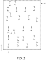
- the wireless communication network 26 is formed by an arrangement of communication nodes 27-50 comprising, for example, ZigBee-like radio modules.
- the communication nodes 27-48 are each associated with a particular luminaire 2-23.
- Two further communication nodes 49, 50 are associated with the switch boxes 24, 25 respectively.
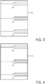
- the first switch box 24 comprises three switches 52-54 adapted to control three separate groups of luminaires within the lighting array 1.
- each switch 52-54 is a selector switch configured such that it is able to apply a series of predetermined settings to a particular control group of luminaires. These setting may correspond, for example, to different brightness levels.
- the second switch box 25 similarly comprises three switches 55-57 adapted for the same means.
- the switch boxes 24, 25 are capable of controlling six groups of luminaires 58-63 in all.
- the luminaires 2-23 are each controlled by one of the communication nodes 27-48, therefore, each node 27-48 must be assigned to one of the six control groups 58-63 before the lighting array 1 can be commissioned.
- the final assignment of nodes 27-48 to control groups 58-63 is shown in Figure 13 .
- the first stage in commissioning the lighting array 1 is to establish the communication network 26. This is achieved by a network discovery process, which is initiated by all communication nodes 27-50 upon power-up. Every communication node 27-50 in the network 26 tunes to a control channel and broadcasts an "advertise" message, which contains its node type and a request that all other nodes identify themselves. After a random time, each other node replies to the message with its identity and functionality. However, the nodes 27-50 are unable to supply their position information. At this stage, therefore, the topology of the network 26 is unknown.
- the topology of the network 26 may be established using a topology generation algorithm 51. Since the structure of the node network 26 is equivalent to the structure of the array of luminaires 2-23 and switch boxes 24, 25, the topology of the network 26 is used to gain an understanding of the structure of the lighting array 1.
- the topology of the network 26 may be established manually or may be pre-defined by some other means, for example by a template corresponding to the locations of the communication nodes 27-50.
- the topology generation algorithm 51 calculates the relative position of each node, and hence luminaire, using range data provided by the wireless communication network 26.
- the range data is provided in the form of range measurements taken between pairs of communication nodes 27-50 in the wireless network 26.
- the calculation of a range between a node and its neighbour is derived directly from these range measurements, which are made using techniques like Received Signal Strength Indication (RSSI) or Time-of-Flight.
- RSSI Received Signal Strength Indication
- Time-of-Flight Time-of-Flight.
- the received strength of a radio signal exchanged between a pair of communication nodes is used to calculate the range between them.
- the strength of the transmitted signal decreases at a rate inversely proportional to the distance travelled and proportional to the wavelength of the signal.
- the distance between the pair of nodes may be calculated from the transmitted signal's attenuation at the receiving node.
- the range between a pair of communication nodes is calculated by measuring the time taken for a radio signal to travel between them. It is known that radio signals travel at the speed of light, hence, an accurate measure of the time-of-flight between the pair of nodes provides an accurate calculation of the distance between them.
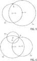
- Figures 5 and 6 show the method by which the topology generation algorithm 51 uses range measurements to derive the positions of the nodes 31, 32, 35, 36 of Figure 2 .
- the topology generation algorithm 51 chooses a first node 32 in the network 26 and assigns it a nominal reference position. It then places a second node 31 at a point on a surrounding circle 32a, the radius of which is defined by the range measurement between the two nodes 32, 31. Further range measurements, made between the first node 32 and third node 36 and between the second node 31 and third node 36, enable the third node 36 to be placed at an intersection between the first circle 32a and a second circle 31a.
- the radius of the second circle 31a defines the distance between the second node 31 and the third node 36. It does not matter for auto-commissioning purposes if the derived topology of the network 26 is reflected or rotated, therefore both of the intersection points between the circles 32a, 31a are valid positions for the third node 36.
- the positions of the three nodes 31, 32, 36 are used, by the topology generation algorithm 51, as a fixed frame of reference for the placement of the fourth node 35 in the network 26.
- the fourth node 35 may be positioned by making three final range measurements. These are made between the first node 32 and fourth node 35; between the second node 31 and fourth node 35; and between the third node 36 and fourth node 35. The measurements are defined by the radii of circles 32b, 31b and 36a respectively and the fourth node 35 is placed at their intersection.
- the topology generation algorithm 51 is able to calculate the positions of the remaining nodes in the network 26 by the same method, using the positions of the first four nodes 31, 32, 35, 36 as reference points.
- the RSSI or Time-of Flight measurements which are used in order to calculate the ranges between nodes 27-50, can be affected by factors such as temperature and battery level.
- errors introduced due to component differences, variations in antenna performance and multipath effects. Such errors are carried through when calculating the ranges between pairs of communication nodes 27-50 and, hence, lead to a level of uncertainty in the derived node positions.
- Figure 2 where it can be seen that the network structure derived by the topology generation algorithm 51 is irregular.
- the structures of lighting arrays are known to be regular in order that they are able to provide a minimum working level of background light.
- the structure of a lighting array may be dictated, for example, by the structure of a false ceiling.
- an assignment algorithm 64 shown in Figure 11 , which is adapted to interpret the derived structure of the lighting array 1.
- the assignment algorithm 64 is configured such that, despite the previously described defects in the derived node positions, it is able to assign the nodes 27-48 to the correct control groups 58-63, as shown in Figure 12 .
- the assignment algorithm 64 is adapted to construct a series of straight lines between communication nodes 27-48.
- the series of lines are constructed in the x-y space of Figure 2 , however, in another embodiment of the invention, the lines may be constructed in x-y-z space. Each constructed line passes through as many nodes as possible, connecting the nodes together to form a spatial group.
- the assignment algorithm 64 is adapted such that it may be implemented, for example, by a laptop computer 65 which communicates with the wireless network 26 through a gateway interface 66.
- the assignment algorithm 64 may similarly be implemented by a handheld computer device, such as a PDA.
- the gateway interface 66 comprises a stand-alone program, running on the computer 65, which requests and collects data from the communication network 26 through a gateway provided by one of the switch box nodes 49, 50.
- the collected data includes the functionality of each node 27-50 and the range measurements between each pair of nodes 27-50.
- the gateway interface 66 continuously monitors the network 26 and is able to detect if new nodes are added to, or disappear from, the network 26.
- the hardware of the computer 65 includes a central processing unit (CPU) 67 for executing the assignment algorithm 64 and for managing and controlling the operation of the computer 65.
- the CPU 67 is connected to a number of devices via a bus 68, the devices including a storage device, for example a hard disk drive 69, and memory devices including ROM 70 and RAM 71.
- the computer hardware further includes a network card 72, which provides means for interfacing to the communication network 26, and a display 73, which allows a user to monitor the operation of the computer 65.
- the laptop computer 65 is adapted to communicate with the gateway via a serial or Ethernet cable. However, in another embodiment of the invention, the computer 65 may communicate with the gateway wirelessly.
- the assignment algorithm 64 is adapted such that it may be implemented by computer hardware which is integrated into the wireless communication network 26. Such hardware could be comprised, for example, as part of the switch box nodes 49, 50.
- the computer 65 requests and receives range data from the wireless communication network 26 through the gateway provided by one of the switch box nodes 49, 50. Using the received range data, the computer 65 implements the topology generation algorithm 51 to establish the topology of the network 26, as previously described.
- the computer 65 implements the assignment algorithm 64 and assigns the nodes 27-48 to control groups 58-63.
- the communication nodes 27-50 are provided with storage means such that they are able to store the assignment configuration.
- the communication nodes 27-50 are then able to implement the stored configuration each time the lighting array 1 is switched on.
- the assignment algorithm 64 comprises a line construction process, a threshold process and a line sorting and selection process.
- the threshold process allows the assignment algorithm 64 to overcome the defects caused by errors in the RSSI or Time-of-Flight measurements, as previously described.
- the assignment algorithm 64 outputs a set of compatible control lines 58-63 which are used to assign the nodes 27-48 into control groups 58-63.
- a constructed line 74 connects a node 75 to another node 76.
- Two further nodes 77, 78 fall within a threshold distance 79 of the line 74 and, hence, the assignment algorithm 64 attaches these two nodes 77, 78 to the line 74 as well.
- the threshold distance 79 is defined perpendicular to the line 74, and is present on both sides. There is, therefore, defined a threshold boundary 79a, 79b on either side of the line 74.
- a third node 80 is positioned too far from the line 74 to fall within the threshold distance 79 and is, therefore, not included. This process is further represented in Figure 11 , step S11.2.
- the assignment algorithm 64 overcomes the defects arising from the ranging process by attaching all nodes 75-78 to the line 74, as long as they are within the threshold distance 79. In this way, the assignment algorithm 64 is configured such that it is able to absorb errors in the individually derived positions of the communication nodes 27-50. The result is that the accuracy of node assignment is vastly improved, meaning that it is far more likely that individual nodes are allocated to the correct control group 58-63. It can be seen from Figure 9 that the node 80 falls outside of the threshold boundaries 79a, 79b, defined by the threshold distance 79, and so it is not included within the control group associated with the line 74.
- the line forms a zigzag like shape 74a.
- the third node 80 is left unattached by the assignment process and therefore does not form part of the spatial group associated with the line 74a.
- step S11.3 once the assignment algorithm 64 has finished constructing lines, it assesses the quality of each line and assigns each line a score.
- the score is based upon the line's length, the number of nodes which the line includes, the standard deviation of the nodes from the straight path of the line and the standard deviation of the distance between nodes on the line.
- the assignment algorithm 64 scores a line as being high quality if it has a long length, includes a large number of nodes and has a small value for the two standard deviations.
- the assignment algorithm 64 sorts the lines, by their score, into a list. The highest scoring line is placed at the top of the list and the lowest scoring line is placed at the bottom. At this stage, it is likely that some nodes in the network 26 will be attached to more than one of the constructed lines.
- the assignment algorithm 64 begins the selection of control groups.
- the algorithm selects the highest scoring line from the list as a first control line and marks all nodes associated with it as being "assigned" in step S11.6.
- the assignment algorithm 64 selects the next highest scoring line from the list, in step S11.7, and checks, in step S11.8, as to whether the line contains any nodes that have already been assigned to the first line by step S11.6.
- the line is accepted as a second control line and the assignment algorithm 64 progresses to step S11.9 by marking all of its nodes as "assigned". Contrastingly, if the second line contains nodes which have already been assigned, the assignment algorithm 64 returns to step S11.7 and tries the next best line from the list. The assignment algorithm 64 further assesses each prospective control line's slope in comparison with the slope of lines which have already been accepted as control lines. Prospective lines which cross over lines already having been accepted are automatically disregarded.
- the assignment algorithm 64 continues in this manner until a second line has been accepted as a control line. It then employs the same procedure to select a third control line. In this way, the assignment algorithm 64 selects control lines which are distinct, i.e. without shared nodes.
- step S11.10 each time a line is accepted, the assignment algorithm 64 checks to see whether all of the lines have been tried. If the answer is no, the algorithm 64 returns to step S11.7 and tries the next line from the list. If the answer is yes, the algorithm 64 progresses to step S11.11. Here, the assignment algorithm 64 checks to see whether 95% of the nodes have been assigned to an accepted control line.
- the assignment algorithm 64 deletes the highest scoring line from the list, in step S11.12a, and returns to step S11.4. Here, all nodes are again marked as "unassigned" and the process of selecting control lines is restarted.
- the assignment of nodes is considered to be successful.
- the assignment algorithm 64 proceeds to attach any remaining unassigned nodes to their nearest accepted control line, in step S11.12b, making the selection of control lines complete.
- Each of the accepted control lines defines a spatial control group 58-63 of communication nodes.
- the determined topology of the network 26 is then consulted to ascertain the appropriate switch box 24, 25 for each of the control groups 58-63 and the appropriate binding commands are sent out to connect the control groups 58-63 to the appropriate switch box 24, 25.
- the network of communication nodes 26 is divided into control groups 58-63.
- the first control group 58 contains a first set of communication nodes 27-30 and is controlled by the first switch 52 in the first switch box 24.
- the second control group 59 contains a second set of communication nodes 31-34 and is controlled by the second switch 53 of the first switch box 24.
- the third control group 60 contains a third set of communication nodes 35-38 and is controlled by the third switch 54 of the first switch box 24.
- the fourth control group 61 contains a fourth set of communication nodes 39-42 and is controlled by the first switch 55 of the second switch box 25.
- the fifth control group 62 contains a fifth set of communication nodes 43-46 and is controlled by the second switch 56 of the second switch box 25.
- the sixth control group 63 contains a sixth set of communication nodes 47, 48 and is controlled by the third switch 57 of the second switch box 25.
- the groups of luminaires 58-63 can be independently controlled, since each is allocated to a separate switch 52-57 inside one of the switch boxes 24, 25.
- the switch boxes 24, 25 may communicate with nearby light sensors in order to provide control inputs to the switches 52-57. Groups of luminaires may then be automatically switched-on in response to ambient light levels falling below a pre-programmed threshold.
- the switches 52-57 may provide a simple on/off function for the luminaires, but the switches 52-57 may be adapted such that they are able to provide a multitude of settings which correspond to varied intensities of light being emitted by the luminaires.
- each control group may be associated with its own light sensor, located close-by, so that it is controlled independently of the other groups.
- the switch boxes 24, 25 may additionally communicate with motion sensors, infrared sensors or the like. Furthermore, the switch boxes 24, 25 may be configured to communicate with a user-actuated control means, such as a switch, dial, touch-screen panel or building management system. In this way, a user could control the various groups of luminaires 58-63 independently in order to customise the lighting settings for a particular circumstance.
- a user-actuated control means such as a switch, dial, touch-screen panel or building management system.
Landscapes
- Engineering & Computer Science (AREA)
- Computer Networks & Wireless Communication (AREA)
- Signal Processing (AREA)
- Databases & Information Systems (AREA)
- Multimedia (AREA)
- Mobile Radio Communication Systems (AREA)
- Circuit Arrangement For Electric Light Sources In General (AREA)
Description
- The present invention relates to identifying the structure of an arrangement of nodes based upon their positioning information and, particularly, to identifying the structure of a wirelessly controlled lighting array.
- A typical wireless lighting array comprises a large number of luminaires and a smaller number of switches and sensors. The luminaires are typically arranged in a regular structure in order that they provide an even level of background light. The individual elements of the lighting array communicate with one another over a wireless communication network, which is formed by an array of communication nodes. The wireless network provides a means for communication between neighbouring luminaires and for communication between the luminaires and the switches or sensors.
- In order to commission such a lighting system, the array of luminaires is divided up into groups such that each group is controlled by a particular switch or sensor. For the lighting system to work correctly, it is important that the luminaires are divided up into sensible spatial control groupings so that each spatial group can be assigned to the closest appropriate switch or sensor. However, before the luminaires are assigned to spatial groups, it is necessary to ascertain their individual positions within the array.
- Document
US2003/0232 598 discloses topology generation algorithms using ranges between nodes established through "time-of-flight" or RSSI measurements.WO0197466 A1 - Correctly understanding the structure of the lighting array is key to making the correct spatial groupings of luminaires. However, the range measurements between communication nodes, which are used to derive the structure of the array, are subject to error. Any such errors in the range measurements are propagated when calculating the relative positions of the individual luminaires, resulting in an erroneous understanding of the array's structure. Consequently, individual luminaires are not placed in the correct spatial group and, hence, are not controlled by the closest appropriate switch or sensor.
- According to the present invention, there is provided a method of grouping a derived spatial arrangement of wireless nodes (27-50) comprising dividing said arrangement into a plurality of spatial groups wherein a particular node is assigned to a particular group if the distance between its spatial position in said arrangement and a defined centre of said group is equal to or less than a defined threshold distance. A particular wireless node is assigned to a particular group if its position in the spatial arrangement of nodes falls within a threshold distance of a point or array of points defining the centre of the particular group.
- The wireless nodes are members of a wireless communication network may comprise electrically powered wireless communication nodes configured such that they are able to communicate with one another in order to control the operation of a wireless lighting array.
- Embodiments of the present invention will now be described, by way of example, with reference to the accompanying drawings, in which:
-
Figure 1 is an illustration showing the structure of a wireless lighting array comprising luminaires and switch boxes. -
Figure 2 is an illustration showing the derived topology of a wireless communication network comprising communication nodes and corresponding to the wireless lighting array ofFigure 1 . -
Figure 3 is a diagram showing the individual switches inside a first switch box. -
Figure 4 is a diagram showing the individual switches inside a second switch box. -
Figure 5 is an illustration of the method by which a topology generation algorithm derives the structure of a communication network. -
Figure 6 is a further illustration of the method by which a topology generation algorithm derives the structure of a communication network. -
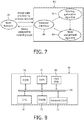
Figure 7 is a diagram showing the implementation of a topology generation algorithm and an assignment algorithm according to the present invention. -
Figure 8 is a block diagram showing a computer architecture configured to implement an assignment algorithm according to the present invention. -
Figure 9 is an illustration showing the creation and the assessment of a constructed control line connecting individual communication nodes together. -
Figure 10 is an illustration showing the assignment of individual communication nodes to a control line. -
Figure 11 is a flow diagram showing the steps associated with the operation of an assignment algorithm according to the present invention. -
Figure 12 is an illustration showing the construction of lines between communication nodes for an entire lighting array. -
Figure 13 is an illustration showing the assignment of communication nodes to control lines for an entire lighting array. - A wireless lighting array, according to the invention, is made up of electrically driven luminaires, which are controlled wirelessly by a smaller number of switches or sensors. Each luminaire is associated with a wireless communication node, which is configured such that it is able to communicate with its neighbouring nodes and with the control switches or sensors. The wireless communication nodes form a wireless network which allows the functionality of each element in the lighting array to be determined.
- Referring to
Figure 1 , awireless lighting array 1 comprises luminaires 2-23 andswitch boxes switch boxes wireless communication network 26, shown inFigure 2 . - The
wireless communication network 26 is formed by an arrangement of communication nodes 27-50 comprising, for example, ZigBee-like radio modules. The communication nodes 27-48 are each associated with a particular luminaire 2-23. Twofurther communication nodes switch boxes - Referring to
Figure 3 , thefirst switch box 24 comprises three switches 52-54 adapted to control three separate groups of luminaires within thelighting array 1. In this embodiment, each switch 52-54 is a selector switch configured such that it is able to apply a series of predetermined settings to a particular control group of luminaires. These setting may correspond, for example, to different brightness levels. Referring toFigure 4 , thesecond switch box 25 similarly comprises three switches 55-57 adapted for the same means. - Accordingly, the
switch boxes lighting array 1 can be commissioned. The final assignment of nodes 27-48 to control groups 58-63 is shown inFigure 13 . - The first stage in commissioning the
lighting array 1 is to establish thecommunication network 26. This is achieved by a network discovery process, which is initiated by all communication nodes 27-50 upon power-up. Every communication node 27-50 in thenetwork 26 tunes to a control channel and broadcasts an "advertise" message, which contains its node type and a request that all other nodes identify themselves. After a random time, each other node replies to the message with its identity and functionality. However, the nodes 27-50 are unable to supply their position information. At this stage, therefore, the topology of thenetwork 26 is unknown. - The topology of the
network 26 may be established using atopology generation algorithm 51. Since the structure of thenode network 26 is equivalent to the structure of the array of luminaires 2-23 andswitch boxes network 26 is used to gain an understanding of the structure of thelighting array 1. - Although the following description is relevant to the derivation of the network topology using a
topology generation algorithm 51, in another embodiment of the invention, the topology of thenetwork 26 may be established manually or may be pre-defined by some other means, for example by a template corresponding to the locations of the communication nodes 27-50. - The
topology generation algorithm 51 calculates the relative position of each node, and hence luminaire, using range data provided by thewireless communication network 26. The range data is provided in the form of range measurements taken between pairs of communication nodes 27-50 in thewireless network 26. The calculation of a range between a node and its neighbour is derived directly from these range measurements, which are made using techniques like Received Signal Strength Indication (RSSI) or Time-of-Flight. - In the case of RSSI, the received strength of a radio signal exchanged between a pair of communication nodes is used to calculate the range between them. The strength of the transmitted signal decreases at a rate inversely proportional to the distance travelled and proportional to the wavelength of the signal. Hence, taking the wavelength into account, the distance between the pair of nodes may be calculated from the transmitted signal's attenuation at the receiving node.
- In the case of Time-of-Flight measurements, the range between a pair of communication nodes is calculated by measuring the time taken for a radio signal to travel between them. It is known that radio signals travel at the speed of light, hence, an accurate measure of the time-of-flight between the pair of nodes provides an accurate calculation of the distance between them.
-
Figures 5 and 6 show the method by which thetopology generation algorithm 51 uses range measurements to derive the positions of thenodes Figure 2 . Following the collection of range data, thetopology generation algorithm 51 chooses afirst node 32 in thenetwork 26 and assigns it a nominal reference position. It then places asecond node 31 at a point on asurrounding circle 32a, the radius of which is defined by the range measurement between the twonodes first node 32 andthird node 36 and between thesecond node 31 andthird node 36, enable thethird node 36 to be placed at an intersection between thefirst circle 32a and asecond circle 31a. - The radius of the
second circle 31a defines the distance between thesecond node 31 and thethird node 36. It does not matter for auto-commissioning purposes if the derived topology of thenetwork 26 is reflected or rotated, therefore both of the intersection points between thecircles third node 36. - Once established, the positions of the three
nodes topology generation algorithm 51, as a fixed frame of reference for the placement of thefourth node 35 in thenetwork 26. - Referring to
Figure 6 , thefourth node 35 may be positioned by making three final range measurements. These are made between thefirst node 32 andfourth node 35; between thesecond node 31 andfourth node 35; and between thethird node 36 andfourth node 35. The measurements are defined by the radii ofcircles fourth node 35 is placed at their intersection. - The
topology generation algorithm 51 is able to calculate the positions of the remaining nodes in thenetwork 26 by the same method, using the positions of the first fournodes - However, the RSSI or Time-of Flight measurements, which are used in order to calculate the ranges between nodes 27-50, can be affected by factors such as temperature and battery level. In addition, there may be errors introduced due to component differences, variations in antenna performance and multipath effects. Such errors are carried through when calculating the ranges between pairs of communication nodes 27-50 and, hence, lead to a level of uncertainty in the derived node positions. This effect is reflected by
Figure 2 , where it can be seen that the network structure derived by thetopology generation algorithm 51 is irregular. Generally, however, the structures of lighting arrays are known to be regular in order that they are able to provide a minimum working level of background light. The structure of a lighting array may be dictated, for example, by the structure of a false ceiling. - In order to overcome this uncertainty and assign the luminaires to the correct control group 58-63, there is provided an
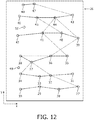
assignment algorithm 64, shown inFigure 11 , which is adapted to interpret the derived structure of thelighting array 1. Theassignment algorithm 64 is configured such that, despite the previously described defects in the derived node positions, it is able to assign the nodes 27-48 to the correct control groups 58-63, as shown inFigure 12 . - In doing this, the
assignment algorithm 64 is adapted to construct a series of straight lines between communication nodes 27-48. In this example of the invention, the series of lines are constructed in the x-y space ofFigure 2 , however, in another embodiment of the invention, the lines may be constructed in x-y-z space. Each constructed line passes through as many nodes as possible, connecting the nodes together to form a spatial group. - Referring to
Figure 7 , theassignment algorithm 64 is adapted such that it may be implemented, for example, by alaptop computer 65 which communicates with thewireless network 26 through agateway interface 66. Theassignment algorithm 64 may similarly be implemented by a handheld computer device, such as a PDA. - The
gateway interface 66 comprises a stand-alone program, running on thecomputer 65, which requests and collects data from thecommunication network 26 through a gateway provided by one of theswitch box nodes gateway interface 66 continuously monitors thenetwork 26 and is able to detect if new nodes are added to, or disappear from, thenetwork 26. - Referring to
Figure 8 , the hardware of thecomputer 65 includes a central processing unit (CPU) 67 for executing theassignment algorithm 64 and for managing and controlling the operation of thecomputer 65. TheCPU 67 is connected to a number of devices via abus 68, the devices including a storage device, for example ahard disk drive 69, and memorydevices including ROM 70 andRAM 71. The computer hardware further includes anetwork card 72, which provides means for interfacing to thecommunication network 26, and adisplay 73, which allows a user to monitor the operation of thecomputer 65. - The
laptop computer 65 is adapted to communicate with the gateway via a serial or Ethernet cable. However, in another embodiment of the invention, thecomputer 65 may communicate with the gateway wirelessly. - In another embodiment of the invention, the
assignment algorithm 64 is adapted such that it may be implemented by computer hardware which is integrated into thewireless communication network 26. Such hardware could be comprised, for example, as part of theswitch box nodes - Again referring to
Figure 7 , in commissioning thelighting array 1, thecomputer 65 requests and receives range data from thewireless communication network 26 through the gateway provided by one of theswitch box nodes computer 65 implements thetopology generation algorithm 51 to establish the topology of thenetwork 26, as previously described. - Following the establishment of the network topology, the
computer 65 implements theassignment algorithm 64 and assigns the nodes 27-48 to control groups 58-63. The communication nodes 27-50 are provided with storage means such that they are able to store the assignment configuration. The communication nodes 27-50 are then able to implement the stored configuration each time thelighting array 1 is switched on. - The
assignment algorithm 64 comprises a line construction process, a threshold process and a line sorting and selection process. The threshold process allows theassignment algorithm 64 to overcome the defects caused by errors in the RSSI or Time-of-Flight measurements, as previously described. - Following the completion of the line sorting and selection process, the
assignment algorithm 64 outputs a set of compatible control lines 58-63 which are used to assign the nodes 27-48 into control groups 58-63. - Referring to
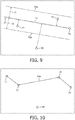
Figure 9 , a constructedline 74 connects anode 75 to anothernode 76. Twofurther nodes threshold distance 79 of theline 74 and, hence, theassignment algorithm 64 attaches these twonodes line 74 as well. In this example, thethreshold distance 79 is defined perpendicular to theline 74, and is present on both sides. There is, therefore, defined athreshold boundary line 74. Athird node 80 is positioned too far from theline 74 to fall within thethreshold distance 79 and is, therefore, not included. This process is further represented inFigure 11 , step S11.2. - The
assignment algorithm 64 overcomes the defects arising from the ranging process by attaching all nodes 75-78 to theline 74, as long as they are within thethreshold distance 79. In this way, theassignment algorithm 64 is configured such that it is able to absorb errors in the individually derived positions of the communication nodes 27-50. The result is that the accuracy of node assignment is vastly improved, meaning that it is far more likely that individual nodes are allocated to the correct control group 58-63. It can be seen fromFigure 9 that thenode 80 falls outside of thethreshold boundaries threshold distance 79, and so it is not included within the control group associated with theline 74. - Referring to
Figure 10 , following the construction of theline 74 and attachment offurther nodes shape 74a. Thethird node 80 is left unattached by the assignment process and therefore does not form part of the spatial group associated with theline 74a. - Referring to
Figure 12 , a series of lines are constructed on thenode network 26. At this stage, many of the nodes 27-48 are attached to multiple lines, making them potential members of multiple control groups. Referring toFigure 11 , S11.4, theassignment algorithm 64 initially marks all nodes as being "unassigned". - Again referring to
Figure 11 , step S11.3, once theassignment algorithm 64 has finished constructing lines, it assesses the quality of each line and assigns each line a score. The score is based upon the line's length, the number of nodes which the line includes, the standard deviation of the nodes from the straight path of the line and the standard deviation of the distance between nodes on the line. - The
assignment algorithm 64 scores a line as being high quality if it has a long length, includes a large number of nodes and has a small value for the two standard deviations. - Once all of the constructed lines have been assigned scores, the
assignment algorithm 64 sorts the lines, by their score, into a list. The highest scoring line is placed at the top of the list and the lowest scoring line is placed at the bottom. At this stage, it is likely that some nodes in thenetwork 26 will be attached to more than one of the constructed lines. - Referring to step S11.5, following the sorting of the lines into quality order, the
assignment algorithm 64 begins the selection of control groups. The algorithm selects the highest scoring line from the list as a first control line and marks all nodes associated with it as being "assigned" in step S11.6. Theassignment algorithm 64 then selects the next highest scoring line from the list, in step S11.7, and checks, in step S11.8, as to whether the line contains any nodes that have already been assigned to the first line by step S11.6. - If the second line does not contain nodes which have already been assigned, the line is accepted as a second control line and the
assignment algorithm 64 progresses to step S11.9 by marking all of its nodes as "assigned". Contrastingly, if the second line contains nodes which have already been assigned, theassignment algorithm 64 returns to step S11.7 and tries the next best line from the list. Theassignment algorithm 64 further assesses each prospective control line's slope in comparison with the slope of lines which have already been accepted as control lines. Prospective lines which cross over lines already having been accepted are automatically disregarded. - The
assignment algorithm 64 continues in this manner until a second line has been accepted as a control line. It then employs the same procedure to select a third control line. In this way, theassignment algorithm 64 selects control lines which are distinct, i.e. without shared nodes. - Referring to step S11.10, each time a line is accepted, the
assignment algorithm 64 checks to see whether all of the lines have been tried. If the answer is no, thealgorithm 64 returns to step S11.7 and tries the next line from the list. If the answer is yes, thealgorithm 64 progresses to step S11.11. Here, theassignment algorithm 64 checks to see whether 95% of the nodes have been assigned to an accepted control line. - If less than 95% of the nodes have been assigned to an accepted line, the
assignment algorithm 64 deletes the highest scoring line from the list, in step S11.12a, and returns to step S11.4. Here, all nodes are again marked as "unassigned" and the process of selecting control lines is restarted. - If, on the other hand, 95% or more of the nodes have been assigned to an accepted control line, the assignment of nodes is considered to be successful. The
assignment algorithm 64 proceeds to attach any remaining unassigned nodes to their nearest accepted control line, in step S11.12b, making the selection of control lines complete. - Each of the accepted control lines defines a spatial control group 58-63 of communication nodes. The determined topology of the
network 26 is then consulted to ascertain theappropriate switch box appropriate switch box - Referring to
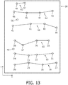
Figure 13 , the network ofcommunication nodes 26 is divided into control groups 58-63. Thefirst control group 58 contains a first set of communication nodes 27-30 and is controlled by thefirst switch 52 in thefirst switch box 24. Thesecond control group 59 contains a second set of communication nodes 31-34 and is controlled by thesecond switch 53 of thefirst switch box 24. Thethird control group 60 contains a third set of communication nodes 35-38 and is controlled by thethird switch 54 of thefirst switch box 24. - The
fourth control group 61 contains a fourth set of communication nodes 39-42 and is controlled by thefirst switch 55 of thesecond switch box 25. Thefifth control group 62 contains a fifth set of communication nodes 43-46 and is controlled by thesecond switch 56 of thesecond switch box 25. Finally, thesixth control group 63 contains a sixth set ofcommunication nodes third switch 57 of thesecond switch box 25. - The groups of luminaires 58-63 can be independently controlled, since each is allocated to a separate switch 52-57 inside one of the
switch boxes - In use, the
switch boxes - The switches 52-57 may provide a simple on/off function for the luminaires, but the switches 52-57 may be adapted such that they are able to provide a multitude of settings which correspond to varied intensities of light being emitted by the luminaires. In order to provide the lighting system with maximum flexibility, each control group may be associated with its own light sensor, located close-by, so that it is controlled independently of the other groups.
- The
switch boxes switch boxes - It will be appreciated that the scope of the invention is not just restricted to wireless lighting arrays, but is also applicable to any type of wireless communication apparatus comprising a series of individual communication nodes. Furthermore, the techniques disclosed here are generally applicable to any positioning application in which a regular structure is to be identified based upon individual position measurements that are subject to error.
- Although claims have been formulated in this application to particular combinations of features, it should be understood that the scope of the disclosure of the present invention also includes any novel features or any novel combination of features disclosed herein either explicitly or implicitly or any generalisation thereof, whether or not it relates to the same invention as presently claimed in any claim and whether or not it mitigates any or all of the same technical problems as does the present invention. The applicants hereby give notice that new claims may be formulated to such features and/or combinations of such features during the prosecution of the present application or of any further application derived therefrom.
Claims (16)
- A method of grouping a derived spatial arrangement of wireless nodes (27-50) comprising dividing said arrangement into a plurality of spatial groups wherein a particular node is assigned to a particular group if the distance between its spatial position in said arrangement and a defined centre of said group is equal to or less than a defined threshold distance.
- A method according to claim 1 wherein the centre of each spatial group is defined by a line which passes through two or more nodes and said distance between a particular node and a particular group's centre is measured as the shortest distance between the node's position in said arrangement and the closest point on the group's centre-defining line.
- A method according to claim 2 including ranking the groups according to the number of assigned nodes therein.
- A method according to claim 2 including ranking the groups according to the statistical dispersion in the distances between the positions of assigned nodes and their centre-defining lines.
- A method according to claim 2 including ranking the groups according to the statistical dispersion in the distances between adjacent assigned nodes.
- A method according to claim 2 including ranking the groups according to the length of their centre-defining lines.
- A method according to any one of claims 1 to 6 including selecting a number of said spatial groups to define independent control groups (58-63).
- A method according to claim 7 including not allowing said nodes (27-50) to be members of more than one of said control groups (58-63).
- A method according to any one of claims 7-8 including binding said control groups (58-63) to appropriate control means if the selection of said control groups (58-63) is successful.
- A method according to claim 9 including establishing said derived arrangement from ranges between pairs of said wireless nodes wherein said ranges are calculated by Received Signal Strength Indication (RSSI).
- A method according to claim 9 including establishing said derived arrangement from ranges between pairs of said wireless nodes wherein said ranges are calculated from time-of-flight measurements.
- Apparatus configured to group a derived arrangement of wireless nodes (27-50) comprising means operable to divide said arrangement into a plurality of spatial groups wherein a particular node is assigned to a particular group if the distance between its spatial position in said arrangement and a defined centre of said group is equal to or less than a defined threshold distance.
- Apparatus according to claim 12 wherein said wireless nodes (27-50) are electrically powered communication nodes in a wireless communication network (26).
- Apparatus according to claim 13 wherein said wireless communication network (26) is configured such that it is able to control the operation of a wireless lighting array (1).
- Apparatus according to claim 14 wherein each of said wireless nodes (27-50) is associated with a luminaire (2-23) or a switch box (24, 25) comprising part of the wireless lighting array (1), said switch boxes (24, 25) being configured to control the operation of the luminaires (2-23).
- A computer program adapted to perform the method of any one of claims 1-11 when implemented by a processor.
Priority Applications (1)
| Application Number | Priority Date | Filing Date | Title |
|---|---|---|---|
| EP07713193.6A EP1994686B1 (en) | 2006-03-06 | 2007-03-05 | Using position for node grouping |
Applications Claiming Priority (3)
| Application Number | Priority Date | Filing Date | Title |
|---|---|---|---|
| EP06110707 | 2006-03-06 | ||
| PCT/IB2007/050712 WO2007102114A1 (en) | 2006-03-06 | 2007-03-05 | Using position for node grouping |
| EP07713193.6A EP1994686B1 (en) | 2006-03-06 | 2007-03-05 | Using position for node grouping |
Publications (2)
| Publication Number | Publication Date |
|---|---|
| EP1994686A1 EP1994686A1 (en) | 2008-11-26 |
| EP1994686B1 true EP1994686B1 (en) | 2018-08-01 |
Family
ID=38162219
Family Applications (1)
| Application Number | Title | Priority Date | Filing Date |
|---|---|---|---|
| EP07713193.6A Active EP1994686B1 (en) | 2006-03-06 | 2007-03-05 | Using position for node grouping |
Country Status (5)
| Country | Link |
|---|---|
| US (1) | US8300577B2 (en) |
| EP (1) | EP1994686B1 (en) |
| JP (1) | JP5081167B2 (en) |
| CN (1) | CN101401355B (en) |
| WO (1) | WO2007102114A1 (en) |
Families Citing this family (30)
| Publication number | Priority date | Publication date | Assignee | Title |
|---|---|---|---|---|
| KR20100127235A (en) * | 2008-02-18 | 2010-12-03 | 코닌클리즈케 필립스 일렉트로닉스 엔.브이. | Localization of lighting fixtures |
| EP2274957A4 (en) * | 2008-04-14 | 2012-09-26 | Digital Lumens Inc | MODULAR LIGHTING SYSTEMS |
| WO2010010493A2 (en) * | 2008-07-21 | 2010-01-28 | Koninklijke Philips Electronics N.V. | Method of setting up a luminaire and luminaire to apply the method |
| KR20110131226A (en) | 2009-02-26 | 2011-12-06 | 코닌클리즈케 필립스 일렉트로닉스 엔.브이. | Routing of messages through a network of interconnecting devices in a network control system |
| EP2401893A1 (en) | 2009-02-26 | 2012-01-04 | Koninklijke Philips Electronics N.V. | Automatically commissioning of devices of a networked control system |
| BR112012001301A2 (en) | 2009-07-24 | 2018-04-03 | Koninklijke Philips Electrnics N. V. | method for networked control system device interconnect networks, program and computer, programmed computer record carrier system for networked control system device interconnect networks and portal node that is adapted for application in a system. |
| US9526149B2 (en) | 2009-11-03 | 2016-12-20 | Philips Lighting Holding B.V. | Object-sensing lighting network and control system therefor |
| US8981913B2 (en) * | 2010-02-18 | 2015-03-17 | Redwood Systems, Inc. | Commissioning lighting systems |
| US9572228B2 (en) | 2010-02-18 | 2017-02-14 | Redwood Systems, Inc. | Commissioning lighting systems |
| IT1401630B1 (en) * | 2010-08-13 | 2013-07-26 | St Microelectronics Srl | LOCALIZATION SYSTEM FOR THE MONITORING OF STREET LIGHTING |
| CA2830991C (en) * | 2011-03-21 | 2020-11-17 | Digital Lumens Incorporated | Methods, apparatus and systems for providing occupancy-based variable lighting |
| US9996057B2 (en) * | 2011-06-07 | 2018-06-12 | Philips Lighting Holding B.V. | Methods for automatically commissioning of devices of a networked control system |
| CN103765988B (en) | 2011-08-17 | 2016-02-10 | 皇家飞利浦有限公司 | For the method and system positioned in DC illumination and power grid |
| WO2013057646A1 (en) * | 2011-10-17 | 2013-04-25 | Koninklijke Philips Electronics N.V. | Commissioning lighting systems |
| US10174924B1 (en) * | 2011-12-30 | 2019-01-08 | Gary K. MART | Heat sink for an LED light fixture |
| EP2685793B1 (en) | 2012-07-12 | 2019-09-04 | LG Innotek Co., Ltd. | Lighting control method and lighting control system |
| US9839102B2 (en) | 2012-07-12 | 2017-12-05 | Lg Innotek Co., Ltd. | Lighting control method and lighting control system |
| CN104956773B (en) * | 2013-02-01 | 2017-09-15 | 飞利浦灯具控股公司 | Via the automatic packet of light and sound |
| WO2014198533A2 (en) * | 2013-06-14 | 2014-12-18 | Koninklijke Philips N.V. | System comprising a controlling device and a controlled device |
| CN105960829B (en) * | 2013-11-29 | 2020-02-28 | 飞利浦灯具控股公司 | Zigbee optical link network debugging |
| US9820364B2 (en) | 2014-08-14 | 2017-11-14 | Philips Lighting Holding B.V. | Commissioning system for a lighting system |
| RU2725977C2 (en) * | 2015-09-04 | 2020-07-08 | Филипс Лайтинг Холдинг Б.В. | Lamps with possibility of wireless communication |
| US10021758B2 (en) | 2016-03-11 | 2018-07-10 | Gooee Limited | Sensor board for luminaire/lighting system |
| US9949331B1 (en) * | 2017-05-01 | 2018-04-17 | Gooee Limited | Automated luminaire identification and group assignment |
| JP6837255B2 (en) * | 2016-09-06 | 2021-03-03 | Necソリューションイノベータ株式会社 | How to set the light emission control of each light emission tool in the area, and how to control the light emission |
| US10122455B1 (en) | 2017-05-01 | 2018-11-06 | Gooee Limited | VLC/DLC Sectorized communication |
| US9980337B1 (en) | 2017-05-01 | 2018-05-22 | Gooee Limited | Automated luminaire location identification and group assignment using light based sectorized communication for commissioning a lighting control system |
| US10045415B1 (en) | 2017-05-01 | 2018-08-07 | Gooee Limited | Automated luminaire location identification and group assignment using light based communication for commissioning a lighting control system |
| US9992838B1 (en) | 2017-05-01 | 2018-06-05 | Gooee Limited | Automated luminaire identification and group assignment devices, systems, and methods using dimming function |
| KR102426505B1 (en) * | 2021-04-16 | 2022-07-29 | 주식회사 바이더엠 | Wireless control lighting system for underground common duct |
Family Cites Families (16)
| Publication number | Priority date | Publication date | Assignee | Title |
|---|---|---|---|---|
| US6240098B1 (en) * | 1995-08-22 | 2001-05-29 | Thomson-Csf | Method and device for space division multiplexing of radio signals transmitted in cellular radio communications |
| AU2001264106A1 (en) | 2000-06-13 | 2001-12-24 | Red-M (Communications) Limited | Network configuration method and system |
| US7161556B2 (en) | 2000-08-07 | 2007-01-09 | Color Kinetics Incorporated | Systems and methods for programming illumination devices |
| WO2002013490A2 (en) | 2000-08-07 | 2002-02-14 | Color Kinetics Incorporated | Automatic configuration systems and methods for lighting and other applications |
| JP2002075663A (en) * | 2000-08-31 | 2002-03-15 | Matsushita Electric Works Ltd | Illumination equipment |
| US6850502B1 (en) * | 2000-10-30 | 2005-02-01 | Radiant Networks, Plc | Join process method for admitting a node to a wireless mesh network |
| US7035240B1 (en) * | 2000-12-27 | 2006-04-25 | Massachusetts Institute Of Technology | Method for low-energy adaptive clustering hierarchy |
| CN1167231C (en) * | 2001-04-06 | 2004-09-15 | 华为技术有限公司 | Method and system for realizing node location and status information query in intelligent network |
| US7417556B2 (en) | 2001-04-24 | 2008-08-26 | Koninklijke Philips Electronics N.V. | Wireless addressable lighting method and apparatus |
| EP1261228B1 (en) * | 2001-05-25 | 2005-04-06 | NTT DoCoMo, Inc. | Radio communication system for reducing interferences with respect to other communication system using close frequency band |
| US6859644B2 (en) | 2002-03-13 | 2005-02-22 | Koninklijke Philips Electronics N.V. | Initialization of wireless-controlled lighting systems |
| US20030232598A1 (en) | 2002-06-13 | 2003-12-18 | Daniel Aljadeff | Method and apparatus for intrusion management in a wireless network using physical location determination |
| KR100530233B1 (en) * | 2003-02-17 | 2005-11-22 | 삼성전자주식회사 | Wireless communication device notifying the connectable device and communication method in the device |
| US7181228B2 (en) * | 2003-12-31 | 2007-02-20 | Corporation For National Research Initiatives | System and method for establishing and monitoring the relative location of group members |
| JP2006238371A (en) * | 2005-02-28 | 2006-09-07 | Toshiba Lighting & Technology Corp | Lighting control system |
| US7639988B2 (en) * | 2005-03-07 | 2009-12-29 | Alcatel-Lucent Usa Inc. | Methods of simplifying network simulation |
-
2007
- 2007-03-05 JP JP2008557871A patent/JP5081167B2/en active Active
- 2007-03-05 US US12/281,489 patent/US8300577B2/en active Active
- 2007-03-05 WO PCT/IB2007/050712 patent/WO2007102114A1/en active Application Filing
- 2007-03-05 EP EP07713193.6A patent/EP1994686B1/en active Active
- 2007-03-05 CN CN200780008239.1A patent/CN101401355B/en active Active
Also Published As
| Publication number | Publication date |
|---|---|
| JP5081167B2 (en) | 2012-11-21 |
| CN101401355A (en) | 2009-04-01 |
| WO2007102114A1 (en) | 2007-09-13 |
| US20110122796A1 (en) | 2011-05-26 |
| CN101401355B (en) | 2014-10-29 |
| US8300577B2 (en) | 2012-10-30 |
| JP2009529279A (en) | 2009-08-13 |
| EP1994686A1 (en) | 2008-11-26 |
Similar Documents
| Publication | Publication Date | Title |
|---|---|---|
| EP1994686B1 (en) | Using position for node grouping | |
| EP1994803B1 (en) | Use of decision trees for automatic commissioning. | |
| US8323081B2 (en) | Positioning system, air conditioning system, and lighting system | |
| ES2319460T3 (en) | GROUPING OF WIRELESS LIGHTING NODES ACCORDING TO THE PROVISION OF ROOMS IN A BUILDING. | |
| US9055451B2 (en) | Indoor position determination method and system based on WLAN signal strength | |
| EP3008937B1 (en) | Optimization system for distributed antenna system | |
| US20090066473A1 (en) | Commissioning wireless network devices according to an installation plan | |
| KR20070121730A (en) | Find walls for wireless light assignment | |
| JP5127807B2 (en) | Wireless positioning system, wireless positioning method, and program | |
| EP2338071A1 (en) | Method and apparatus for automatic assigning of devices | |
| KR102518422B1 (en) | Method, Apparatus and System for Positioning | |
| KR101775513B1 (en) | Apparatus and method for measuring position of light | |
| KR20050103828A (en) | Method for setting automatic address for communication of multi air-conditioner | |
| TWI542895B (en) | Indoor positioning system and method using the same | |
| KR101079847B1 (en) | Method and system for calculation position of tag node in sensor network | |
| JP7316563B2 (en) | Mapping device and method | |
| CN101114964A (en) | A Client Node Location Method for Wireless Mesh Network | |
| CN111156671B (en) | Air conditioner control method and device and air conditioner | |
| CN114050880B (en) | Method and system for testing signal coverage of near field communication chip | |
| US20110164573A1 (en) | Method and apparatus for assigning channel in ad-hoc network | |
| EP3672335B1 (en) | A method of and device for commissioning a lighting system | |
| US20230142829A1 (en) | Autonomous room boundary detection and classification with low resolution sensors | |
| Ma et al. | Design of a novel localization scheme by combining grid and laser | |
| JPH0719862A (en) | Distance measuring device | |
| JP2015091054A (en) | Information processing system, position specifying method, and position specifying program |
Legal Events
| Date | Code | Title | Description |
|---|---|---|---|
| PUAI | Public reference made under article 153(3) epc to a published international application that has entered the european phase |
Free format text: ORIGINAL CODE: 0009012 |
|
| 17P | Request for examination filed |
Effective date: 20081006 |
|
| AK | Designated contracting states |
Kind code of ref document: A1 Designated state(s): AT BE BG CH CY CZ DE DK EE ES FI FR GB GR HU IE IS IT LI LT LU LV MC MT NL PL PT RO SE SI SK TR |
|
| DAX | Request for extension of the european patent (deleted) | ||
| 17Q | First examination report despatched |
Effective date: 20130307 |
|
| RAP1 | Party data changed (applicant data changed or rights of an application transferred) |
Owner name: KONINKLIJKE PHILIPS N.V. |
|
| RAP1 | Party data changed (applicant data changed or rights of an application transferred) |
Owner name: KONINKLIJKE PHILIPS N.V. Owner name: PHILIPS LIGHTING HOLDING B.V. |
|
| REG | Reference to a national code |
Ref country code: DE Ref legal event code: R079 Ref document number: 602007055564 Country of ref document: DE Free format text: PREVIOUS MAIN CLASS: H04L0012280000 Ipc: H04W0004080000 |
|
| GRAP | Despatch of communication of intention to grant a patent |
Free format text: ORIGINAL CODE: EPIDOSNIGR1 |
|
| STAA | Information on the status of an ep patent application or granted ep patent |
Free format text: STATUS: GRANT OF PATENT IS INTENDED |
|
| RIC1 | Information provided on ipc code assigned before grant |
Ipc: H04W 4/18 20090101ALI20180125BHEP Ipc: H04W 64/00 20090101ALI20180125BHEP Ipc: H04W 4/08 20090101AFI20180125BHEP Ipc: H05B 37/02 20060101ALI20180125BHEP Ipc: H04W 8/18 20090101ALI20180125BHEP Ipc: H04L 12/24 20060101ALI20180125BHEP |
|
| INTG | Intention to grant announced |
Effective date: 20180219 |
|
| GRAS | Grant fee paid |
Free format text: ORIGINAL CODE: EPIDOSNIGR3 |
|
| GRAA | (expected) grant |
Free format text: ORIGINAL CODE: 0009210 |
|
| STAA | Information on the status of an ep patent application or granted ep patent |
Free format text: STATUS: THE PATENT HAS BEEN GRANTED |
|
| AK | Designated contracting states |
Kind code of ref document: B1 Designated state(s): AT BE BG CH CY CZ DE DK EE ES FI FR GB GR HU IE IS IT LI LT LU LV MC MT NL PL PT RO SE SI SK TR |
|
| REG | Reference to a national code |
Ref country code: GB Ref legal event code: FG4D |
|
| REG | Reference to a national code |
Ref country code: CH Ref legal event code: EP Ref country code: AT Ref legal event code: REF Ref document number: 1025783 Country of ref document: AT Kind code of ref document: T Effective date: 20180815 |
|
| REG | Reference to a national code |
Ref country code: IE Ref legal event code: FG4D |
|
| REG | Reference to a national code |
Ref country code: DE Ref legal event code: R096 Ref document number: 602007055564 Country of ref document: DE |
|
| REG | Reference to a national code |
Ref country code: NL Ref legal event code: MP Effective date: 20180801 |
|
| RAP2 | Party data changed (patent owner data changed or rights of a patent transferred) |
Owner name: KONINKLIJKE PHILIPS N.V. Owner name: PHILIPS LIGHTING HOLDING B.V. |
|
| REG | Reference to a national code |
Ref country code: LT Ref legal event code: MG4D |
|
| REG | Reference to a national code |
Ref country code: AT Ref legal event code: MK05 Ref document number: 1025783 Country of ref document: AT Kind code of ref document: T Effective date: 20180801 |
|
| PG25 | Lapsed in a contracting state [announced via postgrant information from national office to epo] |
Ref country code: GR Free format text: LAPSE BECAUSE OF FAILURE TO SUBMIT A TRANSLATION OF THE DESCRIPTION OR TO PAY THE FEE WITHIN THE PRESCRIBED TIME-LIMIT Effective date: 20181102 Ref country code: SE Free format text: LAPSE BECAUSE OF FAILURE TO SUBMIT A TRANSLATION OF THE DESCRIPTION OR TO PAY THE FEE WITHIN THE PRESCRIBED TIME-LIMIT Effective date: 20180801 Ref country code: FI Free format text: LAPSE BECAUSE OF FAILURE TO SUBMIT A TRANSLATION OF THE DESCRIPTION OR TO PAY THE FEE WITHIN THE PRESCRIBED TIME-LIMIT Effective date: 20180801 Ref country code: LT Free format text: LAPSE BECAUSE OF FAILURE TO SUBMIT A TRANSLATION OF THE DESCRIPTION OR TO PAY THE FEE WITHIN THE PRESCRIBED TIME-LIMIT Effective date: 20180801 Ref country code: PL Free format text: LAPSE BECAUSE OF FAILURE TO SUBMIT A TRANSLATION OF THE DESCRIPTION OR TO PAY THE FEE WITHIN THE PRESCRIBED TIME-LIMIT Effective date: 20180801 Ref country code: NL Free format text: LAPSE BECAUSE OF FAILURE TO SUBMIT A TRANSLATION OF THE DESCRIPTION OR TO PAY THE FEE WITHIN THE PRESCRIBED TIME-LIMIT Effective date: 20180801 Ref country code: IS Free format text: LAPSE BECAUSE OF FAILURE TO SUBMIT A TRANSLATION OF THE DESCRIPTION OR TO PAY THE FEE WITHIN THE PRESCRIBED TIME-LIMIT Effective date: 20181201 Ref country code: AT Free format text: LAPSE BECAUSE OF FAILURE TO SUBMIT A TRANSLATION OF THE DESCRIPTION OR TO PAY THE FEE WITHIN THE PRESCRIBED TIME-LIMIT Effective date: 20180801 Ref country code: BG Free format text: LAPSE BECAUSE OF FAILURE TO SUBMIT A TRANSLATION OF THE DESCRIPTION OR TO PAY THE FEE WITHIN THE PRESCRIBED TIME-LIMIT Effective date: 20181101 |
|
| REG | Reference to a national code |
Ref country code: CH Ref legal event code: PK Free format text: BERICHTIGUNGEN |
|
| RIC2 | Information provided on ipc code assigned after grant |
Ipc: H04W 64/00 20090101ALI20180125BHEP Ipc: H04W 4/08 20090101AFI20180125BHEP Ipc: H04L 12/24 20060101ALI20180125BHEP Ipc: H04W 8/18 20090101ALI20180125BHEP Ipc: H05B 37/02 20060101ALI20180125BHEP Ipc: H04W 4/18 20090101ALI20180125BHEP |
|
| PG25 | Lapsed in a contracting state [announced via postgrant information from national office to epo] |
Ref country code: ES Free format text: LAPSE BECAUSE OF FAILURE TO SUBMIT A TRANSLATION OF THE DESCRIPTION OR TO PAY THE FEE WITHIN THE PRESCRIBED TIME-LIMIT Effective date: 20180801 Ref country code: LV Free format text: LAPSE BECAUSE OF FAILURE TO SUBMIT A TRANSLATION OF THE DESCRIPTION OR TO PAY THE FEE WITHIN THE PRESCRIBED TIME-LIMIT Effective date: 20180801 |
|
| RAP2 | Party data changed (patent owner data changed or rights of a patent transferred) |
Owner name: SIGNIFY HOLDING B.V. Owner name: KONINKLIJKE PHILIPS N.V. |
|
| PG25 | Lapsed in a contracting state [announced via postgrant information from national office to epo] |
Ref country code: EE Free format text: LAPSE BECAUSE OF FAILURE TO SUBMIT A TRANSLATION OF THE DESCRIPTION OR TO PAY THE FEE WITHIN THE PRESCRIBED TIME-LIMIT Effective date: 20180801 Ref country code: RO Free format text: LAPSE BECAUSE OF FAILURE TO SUBMIT A TRANSLATION OF THE DESCRIPTION OR TO PAY THE FEE WITHIN THE PRESCRIBED TIME-LIMIT Effective date: 20180801 Ref country code: CZ Free format text: LAPSE BECAUSE OF FAILURE TO SUBMIT A TRANSLATION OF THE DESCRIPTION OR TO PAY THE FEE WITHIN THE PRESCRIBED TIME-LIMIT Effective date: 20180801 Ref country code: IT Free format text: LAPSE BECAUSE OF FAILURE TO SUBMIT A TRANSLATION OF THE DESCRIPTION OR TO PAY THE FEE WITHIN THE PRESCRIBED TIME-LIMIT Effective date: 20180801 |
|
| REG | Reference to a national code |
Ref country code: DE Ref legal event code: R097 Ref document number: 602007055564 Country of ref document: DE |
|
| PG25 | Lapsed in a contracting state [announced via postgrant information from national office to epo] |
Ref country code: SK Free format text: LAPSE BECAUSE OF FAILURE TO SUBMIT A TRANSLATION OF THE DESCRIPTION OR TO PAY THE FEE WITHIN THE PRESCRIBED TIME-LIMIT Effective date: 20180801 Ref country code: DK Free format text: LAPSE BECAUSE OF FAILURE TO SUBMIT A TRANSLATION OF THE DESCRIPTION OR TO PAY THE FEE WITHIN THE PRESCRIBED TIME-LIMIT Effective date: 20180801 |
|
| PLBE | No opposition filed within time limit |
Free format text: ORIGINAL CODE: 0009261 |
|
| STAA | Information on the status of an ep patent application or granted ep patent |
Free format text: STATUS: NO OPPOSITION FILED WITHIN TIME LIMIT |
|
| 26N | No opposition filed |
Effective date: 20190503 |
|
| PG25 | Lapsed in a contracting state [announced via postgrant information from national office to epo] |
Ref country code: SI Free format text: LAPSE BECAUSE OF FAILURE TO SUBMIT A TRANSLATION OF THE DESCRIPTION OR TO PAY THE FEE WITHIN THE PRESCRIBED TIME-LIMIT Effective date: 20180801 |
|
| PG25 | Lapsed in a contracting state [announced via postgrant information from national office to epo] |
Ref country code: MC Free format text: LAPSE BECAUSE OF FAILURE TO SUBMIT A TRANSLATION OF THE DESCRIPTION OR TO PAY THE FEE WITHIN THE PRESCRIBED TIME-LIMIT Effective date: 20180801 |
|
| REG | Reference to a national code |
Ref country code: CH Ref legal event code: PL |
|
| PG25 | Lapsed in a contracting state [announced via postgrant information from national office to epo] |
Ref country code: LU Free format text: LAPSE BECAUSE OF NON-PAYMENT OF DUE FEES Effective date: 20190305 |
|
| REG | Reference to a national code |
Ref country code: BE Ref legal event code: MM Effective date: 20190331 |
|
| PG25 | Lapsed in a contracting state [announced via postgrant information from national office to epo] |
Ref country code: CH Free format text: LAPSE BECAUSE OF NON-PAYMENT OF DUE FEES Effective date: 20190331 Ref country code: LI Free format text: LAPSE BECAUSE OF NON-PAYMENT OF DUE FEES Effective date: 20190331 Ref country code: IE Free format text: LAPSE BECAUSE OF NON-PAYMENT OF DUE FEES Effective date: 20190305 |
|
| PG25 | Lapsed in a contracting state [announced via postgrant information from national office to epo] |
Ref country code: BE Free format text: LAPSE BECAUSE OF NON-PAYMENT OF DUE FEES Effective date: 20190331 |
|
| PG25 | Lapsed in a contracting state [announced via postgrant information from national office to epo] |
Ref country code: PT Free format text: LAPSE BECAUSE OF FAILURE TO SUBMIT A TRANSLATION OF THE DESCRIPTION OR TO PAY THE FEE WITHIN THE PRESCRIBED TIME-LIMIT Effective date: 20181201 Ref country code: MT Free format text: LAPSE BECAUSE OF NON-PAYMENT OF DUE FEES Effective date: 20190305 |
|
| PG25 | Lapsed in a contracting state [announced via postgrant information from national office to epo] |
Ref country code: CY Free format text: LAPSE BECAUSE OF FAILURE TO SUBMIT A TRANSLATION OF THE DESCRIPTION OR TO PAY THE FEE WITHIN THE PRESCRIBED TIME-LIMIT Effective date: 20180801 |
|
| PG25 | Lapsed in a contracting state [announced via postgrant information from national office to epo] |
Ref country code: HU Free format text: LAPSE BECAUSE OF FAILURE TO SUBMIT A TRANSLATION OF THE DESCRIPTION OR TO PAY THE FEE WITHIN THE PRESCRIBED TIME-LIMIT; INVALID AB INITIO Effective date: 20070305 |
|
| PGFP | Annual fee paid to national office [announced via postgrant information from national office to epo] |
Ref country code: DE Payment date: 20240328 Year of fee payment: 18 Ref country code: GB Payment date: 20240319 Year of fee payment: 18 |
|
| PGFP | Annual fee paid to national office [announced via postgrant information from national office to epo] |
Ref country code: TR Payment date: 20240222 Year of fee payment: 18 Ref country code: FR Payment date: 20240326 Year of fee payment: 18 |