EP1992956A1 - Device and method for measuring magnetic properties of metal material - Google Patents
Device and method for measuring magnetic properties of metal material Download PDFInfo
- Publication number
- EP1992956A1 EP1992956A1 EP07251989A EP07251989A EP1992956A1 EP 1992956 A1 EP1992956 A1 EP 1992956A1 EP 07251989 A EP07251989 A EP 07251989A EP 07251989 A EP07251989 A EP 07251989A EP 1992956 A1 EP1992956 A1 EP 1992956A1
- Authority
- EP
- European Patent Office
- Prior art keywords
- magnetic
- magnet
- metal material
- relative distance
- scale
- Prior art date
- Legal status (The legal status is an assumption and is not a legal conclusion. Google has not performed a legal analysis and makes no representation as to the accuracy of the status listed.)
- Withdrawn
Links
- 239000007769 metal material Substances 0.000 title claims abstract description 61
- 238000000034 method Methods 0.000 title claims abstract description 26
- 230000003993 interaction Effects 0.000 claims abstract description 27
- 229910052782 aluminium Inorganic materials 0.000 claims description 8
- 239000000463 material Substances 0.000 claims description 7
- XAGFODPZIPBFFR-UHFFFAOYSA-N aluminium Chemical group [Al] XAGFODPZIPBFFR-UHFFFAOYSA-N 0.000 claims description 3
- 238000005259 measurement Methods 0.000 description 37
- 238000010586 diagram Methods 0.000 description 12
- 239000000523 sample Substances 0.000 description 8
- 229910000891 Alacrite Inorganic materials 0.000 description 7
- 229910052751 metal Inorganic materials 0.000 description 5
- 239000002184 metal Substances 0.000 description 5
- 230000005415 magnetization Effects 0.000 description 2
- 238000012986 modification Methods 0.000 description 2
- 230000004048 modification Effects 0.000 description 2
- 229910001220 stainless steel Inorganic materials 0.000 description 2
- 239000010935 stainless steel Substances 0.000 description 2
- 230000000593 degrading effect Effects 0.000 description 1
- 239000002019 doping agent Substances 0.000 description 1
- 238000002474 experimental method Methods 0.000 description 1
- 230000005484 gravity Effects 0.000 description 1
- -1 i.e. Substances 0.000 description 1
- 238000000691 measurement method Methods 0.000 description 1
- 239000013074 reference sample Substances 0.000 description 1
Images



Classifications
-
- G—PHYSICS
- G01—MEASURING; TESTING
- G01R—MEASURING ELECTRIC VARIABLES; MEASURING MAGNETIC VARIABLES
- G01R33/00—Arrangements or instruments for measuring magnetic variables
- G01R33/12—Measuring magnetic properties of articles or specimens of solids or fluids
- G01R33/16—Measuring susceptibility
Definitions
- the present invention relates to a device and a method for measuring magnetic properties. More particularly, the present invention relates to a device and a method for measuring the magnetic properties of a metal material.
- magnetic properties of a metal object under measurement are generally deduced from the reading variation of a scale, thus achieving the measurement of data of the magnetic properties of a metal material.
- a weight serving as a reference sample must be used and the measurement must be performed in a fixed distance.
- the distance refers to the distance between the object under measurement and a magnet.
- the conventional art adopts fixed points, so measurements are made at each single point every time. Therefore, the magnetic properties of the metal object under measurement cannot be measured over a continuous distance. Furthermore, in the conventional art, the object under measurement cannot be measured until it is calibrated against a standard weight. Therefore, the magnetic properties of the object under measurement cannot be measured directly, thereby degrading the precision of the conventional art.
- Our invention provides method and device for directly measuring the object under measurement without using the standard weight. Furthermore, a continuous multi-point measurement method and device are also needed.
- the present invention seeks to provide a device for measuring magnetic properties of a metal material.
- the device comprises a magnet for generating a magnetic field, a scale, a hanger, and a distance meter.
- the magnet is set on the scale, so as to measure a magnetic interaction force between the magnet and the metal material.
- the hanger is movably arranged above the scale for carrying the metal material. The hanger can be moved up and/or down due to the magnetic interaction force, so that a relative distance exists between the magnet and the metal material.
- the distance meter is used to measure the relative distance.
- a magnetic property value of the metal material can be calculated from the magnetic interaction force and the relative distance, thereby obtaining the magnetic properties of the metal material.
- the present invention also seeks to provide a device for measuring magnetic properties, so as to measure the magnetic property value of a magnet.
- the device includes a magnet, a scale, a hanger, and a distance meter.
- the magnet is used to generate a magnetic field.
- the magnet is set on the scale, and the scale is used to measure a magnetic interaction force between the magnet and a reference metal material.
- the hanger is movably arranged above the scale for carrying the reference metal material. The hanger can be moved up and/or down due to the magnetic interaction force, so that a relative distance exists between the magnet and the reference metal material.
- the distance meter is disposed at a position where the relative distance can be measured.
- a magnetic property value of the magnet is calculated from the magnetic interaction force and the relative distance.
- the magnetic property value is, for example, a magnetic moment, a magnetic force, or a magnetic force variation, etc.
- the present invention also seeks to provide a method for measuring the magnetic properties of a metal material. Firstly, the material metal is placed on a movable hanger, and a magnet is placed on a scale. In this way, a magnetic interaction is generated between metal material and the magnet, so as to move the hanger up and/or down. Next, under the balance of the magnetic interaction, a reading of the scale is read and the relative distance between the metal material and the magnet is measured. After that, a magnetic property value of the metal material is calculated from the relative distance and the reading of the scale.
- the distance between the magnet the metal material under measurement can be measured, thereby reducing the measurement time and increasing the flexibility of measurement.
- FIG. 1 is a schematic diagram of the device for measuring the magnetic properties of a metal material according to the present invention.
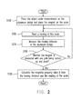
- FIG. 2 is a schematic diagram showing a flow chart of the measuring method according to the present invention.
- FIG. 3 is a schematic diagram of the continuous measurements for the value ⁇ of a sample Alacrite TM .
- FIG. 4 is a schematic diagram of the measurement of the value ⁇ of the sample Alacrite TM at each point.
- FIG. 5 is a schematic diagram of the continuous measurement for the value ⁇ of a sample CHYO4 TM .
- FIG. 6 is a schematic diagram of the measurement of the value ⁇ of the sample CHYO4 TM at each point.
- FIG. 1 is a schematic diagram of the device for measuring the magnetic properties of a metal material according to the present invention.
- the device 100 for measuring magnetic properties is used to measure the magnetic properties of a metal material 130 and comprises a magnet 124, a scale 120, a hanger 110, and a distance meter 140.
- the magnet 124 is used to generate a magnetic field.
- the magnet 124 is set on the scale 120, and the scale 120 is used to measure a magnetic interaction force between the magnet 124 and the metal material 130.
- the hanger 110 is movably arranged above the scale 120 for carrying the metal material 130.
- the hanger 110 can be moved up and down due to the magnetic interaction force, such that a relative distance Z 0 exists between the magnet 124 and the metal material 130.
- the distance meter 140 is disposed at a position where the relative distance Z 0 can be measured.
- a magnetic property value of the metal material 130 is thus calculated by the device 100 from the magnetic interaction force and the relative distance Z 0 , so as to obtain the magnetic properties of the metal material 130.
- the hanger 110 Under the action of the magnetic force between the magnet 124 and the object 130 under measurement, the hanger 110 is moved up and down along the Z direction of the device 100 for measuring magnetic properties. Therefore, the height of the hanger 110 can be adjusted.
- the material of the hanger 110 is preferably a material whose magnetic susceptibility (i.e., the value ⁇ ) is as low as possible, so as to not affect the accuracy of the measurement of magnetic properties.
- the material is, for example, high-grade stainless steel, i.e., stainless steel with minimum dopants, and aluminum is the preferred material.
- the movable hanger 110 is referred to an aluminum bridge 110 in the following description.
- the method of operating the device 100 for measuring magnetic properties is illustrated.
- the magnet 124 is set on the scale 120, for example, a scale pan 122 carries the magnet 124.
- the magnet 124 has a magnetic moment m, which can generate a magnetic field H in the device 100 for measuring magnetic properties.
- a magnetic interaction is generated between the magnet 124 and the metal material 130 under measurement.
- the scale 120 can be an ordinary scale used to measure the mass of an object.
- the scale 120 is used to measure the force generated by the magnetic interaction.
- the reading of the scale 120 varies due to the action of the magnetic force between the magnet 124 and the metal material 130 and the attractive force and the repulsive force generated by gravity.
- the reading read by the scale 120 is expressed by the following formulas.
- Z 0 in formula (1) stands for the distance between the metal material 130 and the magnet 124.
- the aluminum bridge 110 spans over the scale 120, and can be moved up and down along the Z direction. Under the action of the magnetic force between the magnet 124 and the metal material 130, the attractive force and the repulsive force generated by magnetic force, the aluminum bridge 110 is moved up or down, and then reaches a balance state. At this time, the relative distance Z 0 between the magnet 124 and the metal material 130 can be measured by using the distance meter 140.
- the distance meter 140 can be constructed from an interferometer, for example, a 3-axis compact interferometer. With the distance meter 140 in the present invention, the relative distance Z 0 can be measured easily and precisely. Therefore, it solves the problem in the conventional art that the measurement must be performed only at a fixed distance.
- FIG. 2 is a schematic diagram of a flow chart of the measuring method according to the present invention.
- Step S100 the metal material 130 under measurement is placed on the aluminum bridge 110, and the magnet 124 is set on the scale 120.
- the aluminum bridge 100 is moved under the magnetic field created by the magnet between the metal material 130 and the magnet 124.
- steps S102 and S104 under the balance of the magnetic interaction, the reading of the scale 120 is read and the relative distance Z 0 between the metal material 130 and the magnet 124 is measured.
- the reading step and the measuring step are performed without an exact sequence.
- step S106 it is determined whether one of the poles of the magnet 124 is measured respectively in the up and down directions. If it does, in Step S108, a magnetic property value such as the magnetic susceptibility, i.e., the value ⁇ of the metal material 130 is calculated from the reading of the scale and the measured moving distance Z 0 . Turning the magnetic pole (such as the south pole or the north pole) up or down can vary the direction of the magnetic moment of the magnet 124. As a result, the permanent magnetization M Z of the metal material 130 in formula (1) can be eliminated. Otherwise, i.e., the magnetic pole is not turned around, the magnetic pole of the magnet 124 is turned around, and then Steps S 102 and S 104 is performed repeatedly.
- a magnetic property value such as the magnetic susceptibility, i.e., the value ⁇ of the metal material 130 is calculated from the reading of the scale and the measured moving distance Z 0 . Turning the magnetic pole (such as the south pole or the north pole) up or down can vary the direction of the
- Step S108 the magnetic property value of the metal material 130, such as the magnetic susceptibility value ⁇ , can be calculated from the reading and the measured relative distance according to the formula (1).
- FIG. 3 is a schematic diagram showing the continuous measurement for the value ⁇ of a sample Alacrite TM .
- FIG. 4 is a schematic diagram of the measurement of the value ⁇ of the sample Alacrite TM at each point.
- the standard weight Alacrite TM serves as the metal material under measurement, so as to illustrate the feasibility of the device and the method for measuring magnetic properties of this embodiment.
- FIG. 3 shows the relationship between the value ⁇ of the weight Alacrite TM and the distance Z 0 when the north pole of the magnet is turned up and down respectively.
- FIG. 4 shows the results of the measurement of the value ⁇ of the standard weight Alacrite TM over a distance Z at each point by using the above measuring method and device. It can be seen from the results that the value ⁇ is consistent with a standard value. Therefore, it is confirmed that the method and the device are actually feasible.
- FIG. 5 is a schematic diagram of the continuous measurement for the value ⁇ of the sample CHYO4 TM , which shows the results of the measurement of the value ⁇ of the standard weight CHYO4 TM at each point Z in the cases of north pole up and down.
- FIG 6 is a schematic diagram of the measurement of the value ⁇ of the sample CHYO4 TM at each point. Likewise, it can be seen from the results that the value ⁇ is consistent with a standard value. Therefore, it can be confirmed that the method and the device are actually feasible.
- the magnetic property value of the metal under measurement is measured, but the present invention is not limited to this.
- a reference metal material such as a standard weight for reference
- the magnetic properties of the reference metal material are already known, so the device for measuring magnetic properties in the aforementioned embodiment can be used to measure the magnetic moment, the magnetic force, or the magnetic force variation of the magnet.
- the magnetic moment, the magnetic force, or the magnetic force variation can be determined from the relative distance between the magnet and the reference metal material, i.e., is determined from the aforementioned moving distance Z 0 .
- the present invention can be used to measure the distance between the magnet and the metal material under measurement, reduce the measurement time, and improve the flexibility of measurement.
- the distance Z 0 can be directly measured by using the action of the magnetic force between the magnet and the object under measurement without using a standard weight. Therefore, the distance Z 0 can ensure a high precision of the data of measurement.
- the analysis is performed by using the dipole moment and the second-order dipole moment, thus the present invention is more precise than the conventional art.
Landscapes
- Physics & Mathematics (AREA)
- Condensed Matter Physics & Semiconductors (AREA)
- General Physics & Mathematics (AREA)
- Investigating Or Analyzing Materials By The Use Of Magnetic Means (AREA)
Abstract
Description
- The present invention relates to a device and a method for measuring magnetic properties. More particularly, the present invention relates to a device and a method for measuring the magnetic properties of a metal material.
- Usually, magnetic properties of a metal object under measurement are generally deduced from the reading variation of a scale, thus achieving the measurement of data of the magnetic properties of a metal material. Currently, a weight serving as a reference sample must be used and the measurement must be performed in a fixed distance. Herein, the distance refers to the distance between the object under measurement and a magnet.
- The conventional art adopts fixed points, so measurements are made at each single point every time. Therefore, the magnetic properties of the metal object under measurement cannot be measured over a continuous distance. Furthermore, in the conventional art, the object under measurement cannot be measured until it is calibrated against a standard weight. Therefore, the magnetic properties of the object under measurement cannot be measured directly, thereby degrading the precision of the conventional art.
- Our invention provides method and device for directly measuring the object under measurement without using the standard weight. Furthermore, a continuous multi-point measurement method and device are also needed.
- In view of the aforementioned problems, the present invention seeks to provide a device for measuring magnetic properties of a metal material. The device comprises a magnet for generating a magnetic field, a scale, a hanger, and a distance meter. The magnet is set on the scale, so as to measure a magnetic interaction force between the magnet and the metal material. The hanger is movably arranged above the scale for carrying the metal material. The hanger can be moved up and/or down due to the magnetic interaction force, so that a relative distance exists between the magnet and the metal material. The distance meter is used to measure the relative distance. A magnetic property value of the metal material can be calculated from the magnetic interaction force and the relative distance, thereby obtaining the magnetic properties of the metal material.
- Furthermore, the present invention also seeks to provide a device for measuring magnetic properties, so as to measure the magnetic property value of a magnet. The device includes a magnet, a scale, a hanger, and a distance meter. The magnet is used to generate a magnetic field. The magnet is set on the scale, and the scale is used to measure a magnetic interaction force between the magnet and a reference metal material. The hanger is movably arranged above the scale for carrying the reference metal material. The hanger can be moved up and/or down due to the magnetic interaction force, so that a relative distance exists between the magnet and the reference metal material. The distance meter is disposed at a position where the relative distance can be measured. A magnetic property value of the magnet is calculated from the magnetic interaction force and the relative distance. The magnetic property value is, for example, a magnetic moment, a magnetic force, or a magnetic force variation, etc.
- Additionally, the present invention also seeks to provide a method for measuring the magnetic properties of a metal material. Firstly, the material metal is placed on a movable hanger, and a magnet is placed on a scale. In this way, a magnetic interaction is generated between metal material and the magnet, so as to move the hanger up and/or down. Next, under the balance of the magnetic interaction, a reading of the scale is read and the relative distance between the metal material and the magnet is measured. After that, a magnetic property value of the metal material is calculated from the relative distance and the reading of the scale.
- With the aforementioned architecture and method of the present invention, the distance between the magnet the metal material under measurement can be measured, thereby reducing the measurement time and increasing the flexibility of measurement.
- In order to the make aforementioned and other objects, features and advantages of the present invention comprehensible, embodiments accompanied with figures are described in detail below.
- It is to be understood that both the foregoing general description and the following detailed description are exemplary, and are intended to provide further explanation of the invention as claimed.
- The accompanying drawings are included to provide a further understanding of the invention, and are incorporated in and constitute a part of this specification. The drawings illustrate embodiments of the invention and, together with the description, serve to explain the principles of the invention.
-
FIG. 1 is a schematic diagram of the device for measuring the magnetic properties of a metal material according to the present invention. -
FIG. 2 is a schematic diagram showing a flow chart of the measuring method according to the present invention. -
FIG. 3 is a schematic diagram of the continuous measurements for the value χ of a sample Alacrite™. -
FIG. 4 is a schematic diagram of the measurement of the value χ of the sample Alacrite™ at each point. -
FIG. 5 is a schematic diagram of the continuous measurement for the value χ of a sample CHYO4™. -
FIG. 6 is a schematic diagram of the measurement of the value χ of the sample CHYO4™ at each point. -
FIG. 1 is a schematic diagram of the device for measuring the magnetic properties of a metal material according to the present invention. As shown inFIG. 1 , in this embodiment, thedevice 100 for measuring magnetic properties is used to measure the magnetic properties of ametal material 130 and comprises amagnet 124, ascale 120, ahanger 110, and adistance meter 140. Themagnet 124 is used to generate a magnetic field. Themagnet 124 is set on thescale 120, and thescale 120 is used to measure a magnetic interaction force between themagnet 124 and themetal material 130. Thehanger 110 is movably arranged above thescale 120 for carrying themetal material 130. Thehanger 110 can be moved up and down due to the magnetic interaction force, such that a relative distance Z0 exists between themagnet 124 and themetal material 130. Thedistance meter 140 is disposed at a position where the relative distance Z0 can be measured. A magnetic property value of themetal material 130 is thus calculated by thedevice 100 from the magnetic interaction force and the relative distance Z0, so as to obtain the magnetic properties of themetal material 130. - Under the action of the magnetic force between the
magnet 124 and theobject 130 under measurement, thehanger 110 is moved up and down along the Z direction of thedevice 100 for measuring magnetic properties. Therefore, the height of thehanger 110 can be adjusted. - In consideration of the measurement of magnetic properties, the material of the
hanger 110 is preferably a material whose magnetic susceptibility (i.e., the value χ) is as low as possible, so as to not affect the accuracy of the measurement of magnetic properties. Generally speaking, the material is, for example, high-grade stainless steel, i.e., stainless steel with minimum dopants, and aluminum is the preferred material. For convenience, themovable hanger 110 is referred to analuminum bridge 110 in the following description. - Referring to
FIG. 1 , the method of operating thedevice 100 for measuring magnetic properties is illustrated. As shown inFIG. 1 , during the measurement, themagnet 124 is set on thescale 120, for example, ascale pan 122 carries themagnet 124. Themagnet 124 has a magnetic moment m, which can generate a magnetic field H in thedevice 100 for measuring magnetic properties. Thus, due to the magnetic field H, a magnetic interaction is generated between themagnet 124 and themetal material 130 under measurement. - The
scale 120 can be an ordinary scale used to measure the mass of an object. Herein, thescale 120 is used to measure the force generated by the magnetic interaction. The reading of thescale 120 varies due to the action of the magnetic force between themagnet 124 and themetal material 130 and the attractive force and the repulsive force generated by gravity. The reading read by thescale 120 is expressed by the following formulas.


where χ stands for the magnetic susceptibility, m stands for the magnetic moment of themagnet 124, Mz stands for the permanent magnetization of themetal material 130, and Hz stands for an Earth's magnetic field. The magnetic moment can be a dipole moment or second-order expansion magnetic moment (a quadrupole moment), and the magnetic force is obtained by expanding a first-order magnetic moment and a second-order expansion magnetic moment (a quadrupole moment). - Furthermore, Z0 in formula (1) stands for the distance between the
metal material 130 and themagnet 124. As described above, thealuminum bridge 110 spans over thescale 120, and can be moved up and down along the Z direction. Under the action of the magnetic force between themagnet 124 and themetal material 130, the attractive force and the repulsive force generated by magnetic force, thealuminum bridge 110 is moved up or down, and then reaches a balance state. At this time, the relative distance Z0 between themagnet 124 and themetal material 130 can be measured by using thedistance meter 140. - The
distance meter 140 can be constructed from an interferometer, for example, a 3-axis compact interferometer. With thedistance meter 140 in the present invention, the relative distance Z0 can be measured easily and precisely. Therefore, it solves the problem in the conventional art that the measurement must be performed only at a fixed distance. -
FIG. 2 is a schematic diagram of a flow chart of the measuring method according to the present invention. As shown inFIGs. 1 and2 , firstly, in Step S100, themetal material 130 under measurement is placed on thealuminum bridge 110, and themagnet 124 is set on thescale 120. Thealuminum bridge 100 is moved under the magnetic field created by the magnet between themetal material 130 and themagnet 124. - In steps S102 and S104, under the balance of the magnetic interaction, the reading of the
scale 120 is read and the relative distance Z0 between themetal material 130 and themagnet 124 is measured. The reading step and the measuring step are performed without an exact sequence. - After that, in step S106, it is determined whether one of the poles of the
magnet 124 is measured respectively in the up and down directions. If it does, in Step S108, a magnetic property value such as the magnetic susceptibility, i.e., the value χ of themetal material 130 is calculated from the reading of the scale and the measured moving distance Z0. Turning the magnetic pole (such as the south pole or the north pole) up or down can vary the direction of the magnetic moment of themagnet 124. As a result, the permanent magnetization MZ of themetal material 130 in formula (1) can be eliminated. Otherwise, i.e., the magnetic pole is not turned around, the magnetic pole of themagnet 124 is turned around, and thenSteps S 102 andS 104 is performed repeatedly. - In Step S108, the magnetic property value of the
metal material 130, such as the magnetic susceptibility value χ, can be calculated from the reading and the measured relative distance according to the formula (1). -
FIG. 3 is a schematic diagram showing the continuous measurement for the value χ of a sample Alacrite™.FIG. 4 is a schematic diagram of the measurement of the value χ of the sample Alacrite™ at each point. Herein, the standard weight Alacrite™ serves as the metal material under measurement, so as to illustrate the feasibility of the device and the method for measuring magnetic properties of this embodiment.FIG. 3 shows the relationship between the value χ of the weight Alacrite™ and the distance Z0 when the north pole of the magnet is turned up and down respectively. Furthermore,FIG. 4 shows the results of the measurement of the value χ of the standard weight Alacrite™ over a distance Z at each point by using the above measuring method and device. It can be seen from the results that the value χ is consistent with a standard value. Therefore, it is confirmed that the method and the device are actually feasible. - Additionally, in this embodiment, a standard weight CHYO4™ is also used to do the same experiment, and the results are shown in
FIGs. 5 and 6 , respectively. Similarly,FIG. 5 is a schematic diagram of the continuous measurement for the value χ of the sample CHYO4™, which shows the results of the measurement of the value χ of the standard weight CHYO4™ at each point Z in the cases of north pole up and down.FIG 6 is a schematic diagram of the measurement of the value χ of the sample CHYO4™ at each point. Likewise, it can be seen from the results that the value χ is consistent with a standard value. Therefore, it can be confirmed that the method and the device are actually feasible. - In the aforementioned embodiment, the magnetic property value of the metal under measurement is measured, but the present invention is not limited to this. By replacing the metal under measurement with a reference metal material, such as a standard weight for reference, the magnetic properties of the reference metal material are already known, so the device for measuring magnetic properties in the aforementioned embodiment can be used to measure the magnetic moment, the magnetic force, or the magnetic force variation of the magnet. The magnetic moment, the magnetic force, or the magnetic force variation can be determined from the relative distance between the magnet and the reference metal material, i.e., is determined from the aforementioned moving distance Z0.
- In view of the above description, with the aforementioned architecture and method, the present invention can be used to measure the distance between the magnet and the metal material under measurement, reduce the measurement time, and improve the flexibility of measurement.
- Furthermore, in this embodiment, the distance Z0 can be directly measured by using the action of the magnetic force between the magnet and the object under measurement without using a standard weight. Therefore, the distance Z0 can ensure a high precision of the data of measurement. In addition, in this embodiment, the analysis is performed by using the dipole moment and the second-order dipole moment, thus the present invention is more precise than the conventional art.
- It will be apparent to those skilled in the art that various modifications and variations can be made to the structure of the present invention without departing from the scope or spirit of the invention. In view of the foregoing, it is intended that the present invention cover modifications and variations of this invention provided they fall within the scope of the following claims and their equivalents.
Claims (26)
- A device for measuring magnetic properties of a metal material, comprising:a magnet, for generating a magnetic field;a scale, on which the magnet is set, for measuring a magnetic interaction force between the magnet and the metal material;a hanger, movably arranged above the scale for carrying the metal material, and capable of moving up and/or down due to the magnetic interaction force, so that a relative distance exists between the magnet and the metal material; anda distance meter, arranged at a position to measure the relative distance,wherein a magnetic property value of the metal material is calculated from the magnetic interaction force and the relative distance.
- A device as claimed in claim 1, wherein the material of the hanger is aluminum.
- A device as claimed in claim 1 or claim 2, wherein the distance meter is an interferometer.
- A device as claimed in any preceding claim, wherein the magnetic property value is a magnetic susceptibility.
- A device for measuring magnetic properties, for measuring a magnetic property value of a magnet, comprising:a magnet, for generating a magnetic field;a scale, on which the magnet is set, for measuring a magnetic interaction force between the magnet and a reference metal material;a hanger, movably arranged above the scale for carrying the reference metal material, and capable of moving up and/or down due to the magnetic interaction force, such that a relative distance exists between the magnet and the reference metal material; anda distance meter, disposed at a position to measure the relative distance,wherein the magnetic property value of the magnet is calculated from the magnetic interaction force and the relative distance.
- A device as claimed in claim 5, wherein the material of the hanger is aluminum.
- A device as claimed in claim 5 or claim 6, wherein the distance meter is an interferometer.
- A device as claimed in any of claims 5 to 7, wherein the magnetic property value is a magnetic moment of the magnet.
- A device as claimed in claim 8, wherein the magnitude of the magnetic moment is determined by the relative distance.
- A device as claimed in claim 9, wherein the magnetic moment is a dipole moment, and the magnetic force is obtained by expanding a first-order magnetic moment and a second-order magnetic moment.
- A device as claimed in claim 9, wherein the magnetic moment is a quadrupole moment.
- A device as claimed in any of claims 5 to 7, wherein the magnetic property value is a magnetic force of the magnet.
- A device as claimed in claim 12, wherein the magnitude of the magnetic force is determined by the relative distance.
- A device as claimed in any of claims 5 to 7, wherein the magnetic property value is a magnetic force variation of the magnet.
- A device as claimed in claim 14, wherein the magnitude of the magnetic force variation is determined by the relative distance.
- A method of measuring magnetic properties of a metal material, comprising:placing a metal material on a hanger, and placing a magnet on a scale, wherein the metal material and the magnet produce a magnetic interaction, so as to move the hanger up and/or down;reading a reading of the scale under the balance of the magnetic interaction, and measuring a relative distance between the metal material and the magnet; andcalculating a magnetic property value of the metal material from the relative distance and the reading of the scale.
- A method as claimed in claim 16, further comprising:turning one of the magnetic poles of the magnet up and down respectively, so as to measure the relative distance.
- A method as claimed in claim 16 or claim 17, further comprising:measuring the relative distance by using an interferometer.
- A method as claimed in any of claims 16 to 18, wherein the magnetic property value is a magnetic susceptibility.
- A method of measuring magnetic properties, comprising:placing a reference metal material on a hanger and placing a magnet on a scale, wherein the reference metal material and the magnet produce a magnetic interaction, so as to move the hanger up and/or down;reading a reading of the scale under the balance of the magnetic interaction, and measuring a relative distance between the metal material and the magnet; andcalculating a magnetic property value of the magnet from the relative distance and the reading of the scale.
- A method as claimed in claim 20, further comprising:turning one of the magnetic poles of the magnet up and down respectively, so as to measure the relative distance.
- A method as claimed in claim 20, further comprising:measuring the relative distance by using an interferometer.
- A method as claimed in any of claims 20 to 22, wherein the magnetic property value is a magnetic moment, a magnetic force, or a magnetic force variation of the magnet.
- A method as claimed in claim 23, wherein the magnitude of the magnetic moment, the magnetic force, or the magnetic force variation is determined by a predetermined distance.
- A method as claimed in claim 23 or claim 24, wherein the magnetic moment is a dipole moment, and the magnetic force is obtained by expanding a first-order magnetic moment and a second-order magnetic moment.
- A method as claimed in claim 23 or claim 24, wherein the magnetic moment is a quadrupole moment.
Priority Applications (1)
| Application Number | Priority Date | Filing Date | Title |
|---|---|---|---|
| EP07251989A EP1992956A1 (en) | 2007-05-15 | 2007-05-15 | Device and method for measuring magnetic properties of metal material |
Applications Claiming Priority (1)
| Application Number | Priority Date | Filing Date | Title |
|---|---|---|---|
| EP07251989A EP1992956A1 (en) | 2007-05-15 | 2007-05-15 | Device and method for measuring magnetic properties of metal material |
Publications (1)
| Publication Number | Publication Date |
|---|---|
| EP1992956A1 true EP1992956A1 (en) | 2008-11-19 |
Family
ID=38694850
Family Applications (1)
| Application Number | Title | Priority Date | Filing Date |
|---|---|---|---|
| EP07251989A Withdrawn EP1992956A1 (en) | 2007-05-15 | 2007-05-15 | Device and method for measuring magnetic properties of metal material |
Country Status (1)
| Country | Link |
|---|---|
| EP (1) | EP1992956A1 (en) |
Cited By (2)
| Publication number | Priority date | Publication date | Assignee | Title |
|---|---|---|---|---|
| CN111856356A (en) * | 2020-07-01 | 2020-10-30 | 四川大学 | Magnetic force testing device and method of magnetic force holding pressure controller using pressure detection |
| CN116794576A (en) * | 2023-06-19 | 2023-09-22 | 瑞声开泰科技(马鞍山)有限公司 | Method and device for judging orientation of magnetic material |
Citations (1)
| Publication number | Priority date | Publication date | Assignee | Title |
|---|---|---|---|---|
| EP0514759A2 (en) * | 1991-05-24 | 1992-11-25 | Seiko Instruments Co., Ltd. | Magnetic characteristics measuring apparatus |
-
2007
- 2007-05-15 EP EP07251989A patent/EP1992956A1/en not_active Withdrawn
Patent Citations (1)
| Publication number | Priority date | Publication date | Assignee | Title |
|---|---|---|---|---|
| EP0514759A2 (en) * | 1991-05-24 | 1992-11-25 | Seiko Instruments Co., Ltd. | Magnetic characteristics measuring apparatus |
Non-Patent Citations (3)
| Title |
|---|
| DAVIS R S ET AL: "New method to measure magnetic susceptibility", MEASUREMENT SCIENCE AND TECHNOLOGY, INSTITUTE OF PHYSICS PUBLISHING, BRISTOL, GB, vol. 4, no. 2, 1 February 1993 (1993-02-01), pages 141 - 147, XP020065382, ISSN: 0957-0233 * |
| HILL G J ET AL: "The influence of positioning errors on susceptibility measurement by the Faraday method", JOURNAL OF PHYSICS E. SCIENTIFIC INSTRUMENTS, INSTITUTE OF PHYSICS PUBLISHING, BRISTOL, GB, vol. 1, no. 1, 1 January 1968 (1968-01-01), pages 52 - 54, XP020017998, ISSN: 0022-3735 * |
| KITA E ET AL: "IN SITU SUSCEPTIBILITY MEASUREMENT OF THE LOW TEMPERATURE MARTENSITIC TRANSFORMATION", IEEE TRANSLATION JOURNAL ON MAGNETICS IN JAPAN, IEEE INC, NEW YORK, US, vol. 8, no. 2, 1 February 1993 (1993-02-01), pages 112 - 117, XP000355475, ISSN: 0882-4959 * |
Cited By (2)
| Publication number | Priority date | Publication date | Assignee | Title |
|---|---|---|---|---|
| CN111856356A (en) * | 2020-07-01 | 2020-10-30 | 四川大学 | Magnetic force testing device and method of magnetic force holding pressure controller using pressure detection |
| CN116794576A (en) * | 2023-06-19 | 2023-09-22 | 瑞声开泰科技(马鞍山)有限公司 | Method and device for judging orientation of magnetic material |
Similar Documents
| Publication | Publication Date | Title |
|---|---|---|
| Barlian et al. | Design and characterization of microfabricated piezoresistive floating element-based shear stress sensors | |
| EP1922550B1 (en) | Method and system for monitoring power flow through an electric power transmission line | |
| Pei et al. | Development of a novel Hall element inclinometer for slope displacement monitoring | |
| CN102721456B (en) | Method for directly calibrating micro thrust and micro impulse | |
| US20080184800A1 (en) | Vibrating Wire Sensor Using Spectral Analysis | |
| CN105066949B (en) | Lane space deformation measuring device and the measuring method based on the device | |
| CN107340545A (en) | A kind of earth magnetism total factor measuring system and method | |
| US20230057869A1 (en) | Resonant frequency-based magnetic sensor at veering zone and method | |
| EP4174438B1 (en) | System and method for determining geographic location of a device | |
| Hernando et al. | Micromagnetics of twisted amorphous ribbons | |
| Song et al. | An NMR technique for rapid measurement of flow | |
| CN102354000A (en) | Orthogonal field calibration device for three-component magnetic probe and calibration method thereof | |
| JP2008039619A (en) | Route guidance system and portable telephone for pedestrian | |
| CN114114109A (en) | Method for measuring micro deformation based on anti-Helmholtz coil | |
| CN212320973U (en) | A test device for circuit breakers | |
| CN203785618U (en) | Detection device for light magnetic axes of metal balls | |
| WO2024175637A1 (en) | Method and apparatus for detecting a dynamical change in a gravitational field | |
| RU2152059C1 (en) | Device for positioning of underground pipeline trajectory | |
| RU134332U1 (en) | PLANT FOR STUDYING PHYSICAL PROCESSES HAPPENING IN HIGH-TEMPERATURE SUPERCONDUCTORS IN AN INHOMOGENEOUS LOCAL MAGNETIC FIELD | |
| CN105241409B (en) | Measure the device and method of Z axis vibration displacement | |
| Batista et al. | Flexural vibrations of a thin clamped steel bar | |
| RU2491650C1 (en) | Installation for research of electromagnetic field of helmholtz coils | |
| CN2708319Y (en) | Electromagnetic damping accelerometer | |
| RU108639U1 (en) | DEVICE FOR DETERMINING THE COERCITIVE FORCE OF FERROMAGNETIC PRODUCTS | |
| CN112379314A (en) | Magnetic field sensor |
Legal Events
| Date | Code | Title | Description |
|---|---|---|---|
| PUAI | Public reference made under article 153(3) epc to a published international application that has entered the european phase |
Free format text: ORIGINAL CODE: 0009012 |
|
| AK | Designated contracting states |
Kind code of ref document: A1 Designated state(s): AT BE BG CH CY CZ DE DK EE ES FI FR GB GR HU IE IS IT LI LT LU LV MC MT NL PL PT RO SE SI SK TR |
|
| AX | Request for extension of the european patent |
Extension state: AL BA HR MK RS |
|
| 17P | Request for examination filed |
Effective date: 20090206 |
|
| 17Q | First examination report despatched |
Effective date: 20090415 |
|
| AKX | Designation fees paid |
Designated state(s): DE |
|
| RTI1 | Title (correction) |
Free format text: DEVICE FOR MEASURING MAGNETIC PROPERTIES OF A METAL MATERIAL OR A MAGNET |
|
| STAA | Information on the status of an ep patent application or granted ep patent |
Free format text: STATUS: THE APPLICATION IS DEEMED TO BE WITHDRAWN |
|
| 18D | Application deemed to be withdrawn |
Effective date: 20100813 |