EP1992907A2 - Method for generating pseudo-random pattern designs for optical position determination systems - Google Patents
Method for generating pseudo-random pattern designs for optical position determination systems Download PDFInfo
- Publication number
- EP1992907A2 EP1992907A2 EP08156125A EP08156125A EP1992907A2 EP 1992907 A2 EP1992907 A2 EP 1992907A2 EP 08156125 A EP08156125 A EP 08156125A EP 08156125 A EP08156125 A EP 08156125A EP 1992907 A2 EP1992907 A2 EP 1992907A2
- Authority
- EP
- European Patent Office
- Prior art keywords
- call
- dot
- input parameters
- write
- dots
- Prior art date
- Legal status (The legal status is an assumption and is not a legal conclusion. Google has not performed a legal analysis and makes no representation as to the accuracy of the status listed.)
- Granted
Links
- 238000000034 method Methods 0.000 title claims abstract description 28
- 230000003287 optical effect Effects 0.000 title description 7
- 239000013598 vector Substances 0.000 description 24
- 101150061388 LON1 gene Proteins 0.000 description 18
- 101100182247 Caenorhabditis elegans lat-1 gene Proteins 0.000 description 14
- 238000010586 diagram Methods 0.000 description 14
- 101150067085 los1 gene Proteins 0.000 description 14
- 238000012634 optical imaging Methods 0.000 description 9
- 101150090997 DLAT gene Proteins 0.000 description 7
- 230000001174 ascending effect Effects 0.000 description 6
- 241000772415 Neovison vison Species 0.000 description 5
- 230000009466 transformation Effects 0.000 description 5
- 101100134883 Caenorhabditis elegans dlat-1 gene Proteins 0.000 description 3
- 241000289690 Xenarthra Species 0.000 description 3
- 238000003860 storage Methods 0.000 description 3
- 238000006073 displacement reaction Methods 0.000 description 2
- 230000009897 systematic effect Effects 0.000 description 2
- 101100256746 Mus musculus Setdb1 gene Proteins 0.000 description 1
- 101100317378 Mus musculus Wnt3 gene Proteins 0.000 description 1
- 101100243367 Phlebia radiata mnp2 gene Proteins 0.000 description 1
- 101100243368 Phlebia radiata mnp3 gene Proteins 0.000 description 1
- 101100184488 Schizosaccharomyces pombe (strain 972 / ATCC 24843) mrpl12 gene Proteins 0.000 description 1
- 101100316510 Schizosaccharomyces pombe (strain 972 / ATCC 24843) usb1 gene Proteins 0.000 description 1
- 230000006978 adaptation Effects 0.000 description 1
- 238000004891 communication Methods 0.000 description 1
- 238000009826 distribution Methods 0.000 description 1
- BJAJDJDODCWPNS-UHFFFAOYSA-N dotp Chemical compound O=C1N2CCOC2=NC2=C1SC=C2 BJAJDJDODCWPNS-UHFFFAOYSA-N 0.000 description 1
- 238000003384 imaging method Methods 0.000 description 1
- 238000004519 manufacturing process Methods 0.000 description 1
- 239000011159 matrix material Substances 0.000 description 1
Images




Classifications
-
- G—PHYSICS
- G01—MEASURING; TESTING
- G01B—MEASURING LENGTH, THICKNESS OR SIMILAR LINEAR DIMENSIONS; MEASURING ANGLES; MEASURING AREAS; MEASURING IRREGULARITIES OF SURFACES OR CONTOURS
- G01B11/00—Measuring arrangements characterised by the use of optical techniques
- G01B11/26—Measuring arrangements characterised by the use of optical techniques for measuring angles or tapers; for testing the alignment of axes
-
- G—PHYSICS
- G01—MEASURING; TESTING
- G01C—MEASURING DISTANCES, LEVELS OR BEARINGS; SURVEYING; NAVIGATION; GYROSCOPIC INSTRUMENTS; PHOTOGRAMMETRY OR VIDEOGRAMMETRY
- G01C15/00—Surveying instruments or accessories not provided for in groups G01C1/00 - G01C13/00
Definitions
- Precision inertial navigation systems can eliminate the need for gimbals by supporting the inertial sensor assembly with a spherically shaped gas supported bearing.
- the angular position of the inertial sensor assembly (sometimes also referred to as the attitude, or roll, pitch and yaw of the inertial sensor assembly) relative to the frame of the craft must be monitored at all times by an optical imaging system that images a reference surface pattern on the surface of the spherically shaped gas supported bearing.
- the gas supported bearing allows rotation of the inertial sensor assembly in all axes without physical contact between an optical sensor in the optical imaging system and the assembly.
- the optical sensor in the optical imaging system of such a precision inertial navigation system generates image signals of at least a portion of a reference surface pattern on the surface of the spherically shaped gas supported bearing.
- the location of the imaged area is determined by comparing the imaged area with a map of the pattern on the surface of the object.
- the inertial navigation system determines the rotation of the imaged area by comparing the angle of the pattern of the imaged area with a map of the pattern on the surface of the object. In this manner, the angular position of a rotating object is disclosed.
- an optical sensor in the optical imaging system is used to image the surface pattern that is patterned on the surface of objects that are moved through the line of sight of the optical sensor. For example, in a manufacturing assembly line, objects may be scanned to determine a position of the object, and a robotic system down-line from the optical imaging system and in communication with the optical imaging system is implemented to reposition the object if necessary.
- the reference surface pattern is typically an array of symbols or shapes that are on the surface of the gas supported bearing or other object.
- the number of shapes and complexity of the shapes that are patterned on the surface of the spherically shaped gas supported bearing constrain the accuracy of the reading of the optical sensor and ultimately, of the inertial navigation system.
- the number of shapes and complexity of the shapes that are patterned on the surface of the assembly line objects constrain the accuracy of the reading of the optical sensor and ultimately, of the position of the object in the assembly line.
- a method for generating a pseudo-random pattern of dots to be patterned on a surface comprising the steps of receiving surface input parameters for the surface, selecting dot locations for the pseudo-random pattern of dots for at least a portion of the surface based on the surface input parameters, and outputting coordinates for dot centers based on the dot locations.
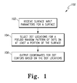
- Figure 1 is a flow diagram of one embodiment of a method 100 for generating a pseudo-random pattern of dots to be patterned on a surface in accordance with the present invention.
- step 102 surface input parameters for a surface are received.
- the surface input parameters for a surface are received at a programmable processor.
- Figure 2 is a pictorial diagram of a system comprising storage medium to cause a programmable processor to generate a pseudo-random pattern of dots.
- a system 130 includes a programmable processor 120 that receives the surface input parameters for the surface. The details for receiving surface input parameters are described below with reference to method 300 of Figure 3 .
- dot locations are selected for a pseudo-random pattern of dots on at least a portion of the surface.
- the selection of dot locations is based on the surface input parameters.
- the system 130 includes a programmable processor 120, which executes a program product, such as software 116 that is embodied on a storage medium 115, to select the dot locations for the pseudo-random pattern of dots to be patterned on the surface.
- a program product such as software 116 that is embodied on a storage medium 115
- pseudo-random pattern is a pattern that incorporates a randomness that overlays a systematic (non-random) structure. The details for selecting the dot locations in a pseudo-random pattern are described below with reference to method 400 of Figure 4 .
- coordinates for dot centers are output based on the dot locations.
- the programmable processor 120 outputs the coordinates for the dot centers.
- the dots When dots are placed at the coordinates for dot centers on the surface having a shape defined by the surface input parameters, the dots form a pseudo-random pattern on the at least a portion of the surface.
- Figure 3 is a flow diagram of one embodiment of a method 300 for receiving surface input parameters in accordance with the present invention.
- the method 300 is implemented by the system 130 of Figure 2 .
- step 302 surface input parameters are received for a surface having a known shape.
- the surface input parameters mathematically describe the known shape with reference to a known coordinate system.
- the programmable processor 120 receives the surface input parameters from a user via a user input interface 121 to the system 130.
- the known shape is a sphere.
- the programmable processor 120 receives surface input parameters for a spherical surface. At least a portion of the surface input parameters for the spherical surface includes a radius of the spherical surface.
- the known shape is a cylindrical surface.
- the programmable processor 120 receives surface input parameters for a cylindrical surface. At least a portion of the surface input parameters includes a radius of the cylindrical surface and a length of the cylindrical surface.
- the known shape is a flat surface.
- the programmable processor 120 receives surface input parameters for a flat surface. At least a portion of the surface input parameters includes at least one length of the flat surface, at least one width of the flat surface, a perpendicular distance from a center to a side, and/or a distance from a center to a vertex. If the flat surface is rectangular, only one length, and one width are required. If the flat surface is a polygon, then the lengths of the edges of the polygon, a perpendicular distance from a center to a side, and/or a distance from a center to a vertex are required.
- the known shape is a combination of at least two of a spherical surface, a cylindrical surface, and a flat surface.
- the programmable processor 120 receives surface input parameters that include at least two of a radius of the spherical surface, a radius of the cylindrical surface, a length of the cylindrical surface, at least one length of the flat surface, at least one width of the flat surface, a perpendicular distance from a center to a side, and/or a distance from a center to a vertex.
- the programmable processor 120 receives surface input parameters that mathematically describe the surfaces that conjoin unlike-surface shapes with reference to a known coordinate system.
- a selected cell area is received.
- the programmable processor 120 receives the selected cell area from a user via the user input interface 121.
- the selected cell area is 0.125 square inches for a sphere having a radius of 5 inches.
- Figure 4 is a flow diagram of one embodiment of a method 400 for selecting dot locations in accordance with the present invention.
- the method 300 is implemented by the system 130 of Figure 2 .
- the surface having the known shape is divided into an integral number of cells, each cell including a non-overlapping cell area approximately equal to the selected cell area.
- the known shape is a spherical shape
- a tessellation approximation is performed for the spherical surface to divide the spherical surface area into an integral number of cells, each cell including a non-overlapping cell area approximately equal to the selected cell area.
- the known shape is a cylindrical shape
- the cylindrical surface is divided into an integral number of cells, each cell including a non-overlapping cell area approximately equal to the selected cell area.
- the known shape is a flat surface
- the flat surface is divided into an integral number of cells, each cell including a non-overlapping cell area approximately equal to the selected cell area.
- one dot location is randomly selected in a respective one of the non-overlapping cell areas.
- a dot location is randomly selected for only a portion of the cells into which the known shape has been divided.
- a dot location is randomly selected for each one of the cells into which the known shape has been divided. Since the cell distribution is systematic (not random) and the dot position within the cell is random, the dot locations are in a pseudo-random pattern. As described above with reference to step 106 of method 100 in Figure 1 , when dots are placed at the output coordinates for dot centers on the surface of an object that has the known shape, the dots form a pseudo-random pattern on the surface of the object.
- the dots' locations were selected for only a portion of the surface, when dots are placed at the output coordinates for dot centers on the surface of an object having the known shape, the dots form a pseudo-random pattern on those portions of the surface of the object for which dot location have been selected.
- the minimum dot density is controlled to be at least 3 per field of view area for an imaging system in which the sphere is to be imaged.
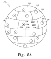
- Figures 5A and 5B are pictorial diagrams of a spherical surface including an integral number of cells upon which a pseudo-random pattern of dots has been patterned.
- Figure 5A is a pictorial diagram of a sphere 210 having a spherical surface 215 that is divided into an integral number of cells represented generally by the numeral 225.
- a pseudo-random pattern of dots represented generally by the numeral 231 has been patterned over the whole spherical surface 215.
- the spherical surface 215 is mathematically described as 4 ⁇ r 2 , where r is the radius of the sphere 210.
- the known coordinate system for the sphere 210 is a polar coordinate system having an origin located within the center of the sphere 210.
- Each dot 231 is centered on a dot center 230.
- the dot center 230 is a point in space on the spherical surface 215. As shown in Figure 5A , there is one dot center 230 located in each cell 225. Each dot center 230 is a point within the dot 231.
- the location of each dot center 230 on the surface 215 of the sphere can be mathematically described. For example, the dot center 230 can be described by polar coordinates using the polar coordinate system having an origin located within the center of the sphere 210.
- a dot 231 can be marked on the spherical surface 215, for example, by dropping an ink dot from an ink jet nozzle, at each of the mathematically described dot centers 230.
- Each cell 225 includes a non-overlapping cell area that includes the area bounded by the cell edges represented generally by the numeral 226.
- cell 225A shown centered in the view of the sphere 210 of Figure 5 , is bounded by edges 226 (A-D).
- edges 226 A-D
- the length of edge 226A and the length of edge 226C are approximately equal.
- the length of edge 226B and the length of edge 226D are approximately equal.
- the cell area is approximately the product of the length of edge 226A and the length of edge 226 B.
- Figure 5B is a pictorial diagram of a sphere 211 having a spherical surface 215 that is divided into an integral number of cells 225.
- the spherical surface 215 is mathematically described as 4 ⁇ r 2 , where r is the radius of the sphere 211.
- a pseudo-random pattern of dots 231 having dot centers 230 has been patterned over a portion of the spherical surface 215.
- the cells 225(A-F) are the portion of cells that includes a dot 231.
- a dot 231 can be marked on the spherical surface 215, for example, by dropping an ink dot from an ink jet nozzle, at each of the mathematically described dot centers 230 in the portion of cells 225 (A-F).
- the sphere 210 is a gas supported bearing for use in an inertial sensor assembly that is monitored by an optical imaging system that images the pseudo-random pattern on the surface 215 of the sphere 210.
- the sphere 211 is a gas supported bearing for use in an inertial sensor assembly that is monitored by an optical imaging system that images the pseudo-random pattern on the surface 215 of the sphere 211.
- Figure 6 is a pictorial diagram of an object 310 that has a complex surface 315 including an integral number of cells represented generally by the numeral 325 upon which a pseudo-random pattern of dots represented generally by the numeral 331 has been patterned. Each dot 331 is centered on a dot center 330.
- the dot center 330 is a point in space on the complex surface 315 of object 310 that is referenced to the three dimensional coordinate space shown by the X, Y, and Z vectors at the origin (0, 0, 0) that form a basis for the three dimensional space.
- the complex surface 315 includes a cylindrical surface 311 conjoined to a flat surface 312.
- the flat surface 312 is rectangularly shaped and is mathematically described by a length L fs and a width W fs .
- the cylindrical surface 311 is mathematically described by a radius R cyl and a length L cyl , which is equal to the length, L fs .
- Each cell 325 includes a non-overlapping cell area that includes the area bounded by the cell edges represented generally by the numeral 326.
- cell 325A shown at the far edge of the flat surface 312 in Figure 6 , is bounded by edges 326 (A-D).
- edges 326A and the length of edge 326C are approximately equal.
- the length of edge 326B and the length of edge 326D are approximately equal.
- the cell area of the cell 325A and all the other cells 325 on the complex surface 315 encompass a surface area or cell area that is approximately the product of the length of edge 326A and the length of edge 326B.
- each dot center 330 located in each cell 325.
- the location of each dot center 330 on the complex surface 315 can be mathematically described with reference to the X, Y, Z coordinate system.
- a dot 331 can be marked on the complex surface 315, for example, by dropping an ink dot from an ink jet nozzle, at each of the mathematically described dot centers 330.
- the dots 331 are only marked on the complex surface 315 in a portion of the cells 325.
- the object 310 that has a complex surface 315 is an object in an assembly line that is monitored by an optical imaging system that images the pseudo-random pattern on the complex surface 315.
- Exemplary software instructions that can be used for selecting dot locations for a pseudo-random pattern of dots on a spherical surface
Landscapes
- Physics & Mathematics (AREA)
- General Physics & Mathematics (AREA)
- Engineering & Computer Science (AREA)
- Radar, Positioning & Navigation (AREA)
- Remote Sensing (AREA)
- Image Processing (AREA)
- Image Analysis (AREA)
- Length Measuring Devices By Optical Means (AREA)
- Position Input By Displaying (AREA)
Abstract
Description
- This application is related to United States Patent Application Serial No. _/_______ (Attorney Docket No. H0014548-5607) having a title of "METHOD AND SYSTEM FOR DETERMINING ANGULAR POSITION OF AN OBJECT" (also referred to here as the "H0014548-5607 Application") filed on the same date herewith. The H0014548-5607 Application is hereby incorporated herein by reference.
- Precision inertial navigation systems can eliminate the need for gimbals by supporting the inertial sensor assembly with a spherically shaped gas supported bearing. During the flight of a craft, the angular position of the inertial sensor assembly (sometimes also referred to as the attitude, or roll, pitch and yaw of the inertial sensor assembly) relative to the frame of the craft must be monitored at all times by an optical imaging system that images a reference surface pattern on the surface of the spherically shaped gas supported bearing. The gas supported bearing allows rotation of the inertial sensor assembly in all axes without physical contact between an optical sensor in the optical imaging system and the assembly.
- The optical sensor in the optical imaging system of such a precision inertial navigation system generates image signals of at least a portion of a reference surface pattern on the surface of the spherically shaped gas supported bearing. When an area of the reference surface pattern on the surface of the bearing is imaged, the location of the imaged area is determined by comparing the imaged area with a map of the pattern on the surface of the object. The inertial navigation system determines the rotation of the imaged area by comparing the angle of the pattern of the imaged area with a map of the pattern on the surface of the object. In this manner, the angular position of a rotating object is disclosed.
- In other applications, an optical sensor in the optical imaging system is used to image the surface pattern that is patterned on the surface of objects that are moved through the line of sight of the optical sensor. For example, in a manufacturing assembly line, objects may be scanned to determine a position of the object, and a robotic system down-line from the optical imaging system and in communication with the optical imaging system is implemented to reposition the object if necessary.
- The reference surface pattern is typically an array of symbols or shapes that are on the surface of the gas supported bearing or other object. The number of shapes and complexity of the shapes that are patterned on the surface of the spherically shaped gas supported bearing constrain the accuracy of the reading of the optical sensor and ultimately, of the inertial navigation system. The number of shapes and complexity of the shapes that are patterned on the surface of the assembly line objects constrain the accuracy of the reading of the optical sensor and ultimately, of the position of the object in the assembly line.
- In one embodiment, a method for generating a pseudo-random pattern of dots to be patterned on a surface comprising the steps of receiving surface input parameters for the surface, selecting dot locations for the pseudo-random pattern of dots for at least a portion of the surface based on the surface input parameters, and outputting coordinates for dot centers based on the dot locations.
-
-
Figure 1 is a flow diagram of one embodiment of a method for generating a pseudo-random pattern of dots to be patterned on a surface in accordance with the present invention. -
Figure 2 is a pictorial diagram of a system comprising storage medium to cause a programmable processor to generate a pseudo-random pattern of dots. -
Figure 3 is a flow diagram of one embodiment of a method for receiving surface input parameters in accordance with the present invention. -
Figure 4 is a flow diagram of one embodiment of a method for selecting dot locations in accordance with the present invention. -
Figures 5A and5B are pictorial diagrams of a spherical surface including an integral number of cells upon which a pseudo-random pattern of dots has been patterned. -
Figure 6 is a pictorial diagram of an object that has a complex surface including an integral number of cells upon which a pseudo-random pattern of dots has been patterned. - In accordance with common practice, the various described features are not drawn to scale but are drawn to emphasize features relevant to the present invention. Reference characters denote like elements throughout figures and text.
- In the following detailed description, reference is made to the accompanying drawings that form a part hereof, and in which is shown by way of illustration specific illustrative embodiments in which the invention may be practiced. These embodiments are described in sufficient detail to enable those skilled in the art to practice the invention, and it is to be understood that other embodiments may be utilized and that logical, mechanical and electrical changes may be made without departing from the scope of the present invention. The following detailed description is, therefore, not to be taken in a limiting sense.
-
Figure 1 is a flow diagram of one embodiment of amethod 100 for generating a pseudo-random pattern of dots to be patterned on a surface in accordance with the present invention. - At
step 102, surface input parameters for a surface are received. In one implementation of this embodiment, the surface input parameters for a surface are received at a programmable processor.Figure 2 is a pictorial diagram of a system comprising storage medium to cause a programmable processor to generate a pseudo-random pattern of dots. In the embodiment shown inFigure 2 , asystem 130 includes aprogrammable processor 120 that receives the surface input parameters for the surface. The details for receiving surface input parameters are described below with reference tomethod 300 ofFigure 3 . - Returning to
method 100, atstep 104, dot locations are selected for a pseudo-random pattern of dots on at least a portion of the surface. The selection of dot locations is based on the surface input parameters. In an embodiment shown inFigure 2 , thesystem 130 includes aprogrammable processor 120, which executes a program product, such assoftware 116 that is embodied on astorage medium 115, to select the dot locations for the pseudo-random pattern of dots to be patterned on the surface. As defined herein, the term pseudo-random pattern is a pattern that incorporates a randomness that overlays a systematic (non-random) structure. The details for selecting the dot locations in a pseudo-random pattern are described below with reference tomethod 400 ofFigure 4 . - At
step 106, coordinates for dot centers are output based on the dot locations. In one implementation of this embodiment, theprogrammable processor 120 outputs the coordinates for the dot centers. When dots are placed at the coordinates for dot centers on the surface having a shape defined by the surface input parameters, the dots form a pseudo-random pattern on the at least a portion of the surface. -
Figure 3 is a flow diagram of one embodiment of amethod 300 for receiving surface input parameters in accordance with the present invention. In some implementations of this embodiment, themethod 300 is implemented by thesystem 130 ofFigure 2 . - At
step 302, surface input parameters are received for a surface having a known shape. The surface input parameters mathematically describe the known shape with reference to a known coordinate system. In one implementation of this embodiment, theprogrammable processor 120 receives the surface input parameters from a user via auser input interface 121 to thesystem 130. - In one implementation of this embodiment, the known shape is a sphere. In this case, the
programmable processor 120 receives surface input parameters for a spherical surface. At least a portion of the surface input parameters for the spherical surface includes a radius of the spherical surface. - In another implementation of this embodiment, the known shape is a cylindrical surface. In this case, the
programmable processor 120 receives surface input parameters for a cylindrical surface. At least a portion of the surface input parameters includes a radius of the cylindrical surface and a length of the cylindrical surface. - In yet another implementation of this embodiment, the known shape is a flat surface. In this case, the
programmable processor 120 receives surface input parameters for a flat surface. At least a portion of the surface input parameters includes at least one length of the flat surface, at least one width of the flat surface, a perpendicular distance from a center to a side, and/or a distance from a center to a vertex. If the flat surface is rectangular, only one length, and one width are required. If the flat surface is a polygon, then the lengths of the edges of the polygon, a perpendicular distance from a center to a side, and/or a distance from a center to a vertex are required. - In yet another implementation of this embodiment, the known shape is a combination of at least two of a spherical surface, a cylindrical surface, and a flat surface. In this case, the
programmable processor 120 receives surface input parameters that include at least two of a radius of the spherical surface, a radius of the cylindrical surface, a length of the cylindrical surface, at least one length of the flat surface, at least one width of the flat surface, a perpendicular distance from a center to a side, and/or a distance from a center to a vertex. In one implementation of this embodiment, theprogrammable processor 120 receives surface input parameters that mathematically describe the surfaces that conjoin unlike-surface shapes with reference to a known coordinate system. - At
step 304, a selected cell area is received. In one implementation of this embodiment, theprogrammable processor 120 receives the selected cell area from a user via theuser input interface 121. In one implementation of this embodiment, the selected cell area is 0.125 square inches for a sphere having a radius of 5 inches. -
Figure 4 is a flow diagram of one embodiment of amethod 400 for selecting dot locations in accordance with the present invention. In some implementations of this embodiment, themethod 300 is implemented by thesystem 130 ofFigure 2 . - At
step 402, the surface having the known shape is divided into an integral number of cells, each cell including a non-overlapping cell area approximately equal to the selected cell area. - In an implementation in which the known shape is a spherical shape, a tessellation approximation is performed for the spherical surface to divide the spherical surface area into an integral number of cells, each cell including a non-overlapping cell area approximately equal to the selected cell area. In an implementation in which the known shape is a cylindrical shape, the cylindrical surface is divided into an integral number of cells, each cell including a non-overlapping cell area approximately equal to the selected cell area. In an implementation in which the known shape is a flat surface, the flat surface is divided into an integral number of cells, each cell including a non-overlapping cell area approximately equal to the selected cell area.
- At
step 404, one dot location is randomly selected in a respective one of the non-overlapping cell areas. In one implementation of this embodiment, a dot location is randomly selected for only a portion of the cells into which the known shape has been divided. In another implementation of this embodiment, a dot location is randomly selected for each one of the cells into which the known shape has been divided. Since the cell distribution is systematic (not random) and the dot position within the cell is random, the dot locations are in a pseudo-random pattern. As described above with reference to step 106 ofmethod 100 inFigure 1 , when dots are placed at the output coordinates for dot centers on the surface of an object that has the known shape, the dots form a pseudo-random pattern on the surface of the object. If the dots' locations were selected for only a portion of the surface, when dots are placed at the output coordinates for dot centers on the surface of an object having the known shape, the dots form a pseudo-random pattern on those portions of the surface of the object for which dot location have been selected. In one implementation of this embodiment, the minimum dot density is controlled to be at least 3 per field of view area for an imaging system in which the sphere is to be imaged. -
Figures 5A and5B are pictorial diagrams of a spherical surface including an integral number of cells upon which a pseudo-random pattern of dots has been patterned.Figure 5A is a pictorial diagram of asphere 210 having aspherical surface 215 that is divided into an integral number of cells represented generally by the numeral 225. A pseudo-random pattern of dots represented generally by the numeral 231 has been patterned over the wholespherical surface 215. Thespherical surface 215 is mathematically described as 4πr2, where r is the radius of thesphere 210. In one implementation of this embodiment, the known coordinate system for thesphere 210 is a polar coordinate system having an origin located within the center of thesphere 210. Eachdot 231 is centered on adot center 230. Thedot center 230 is a point in space on thespherical surface 215. As shown inFigure 5A , there is onedot center 230 located in eachcell 225. Eachdot center 230 is a point within thedot 231. The location of eachdot center 230 on thesurface 215 of the sphere can be mathematically described. For example, thedot center 230 can be described by polar coordinates using the polar coordinate system having an origin located within the center of thesphere 210. Adot 231 can be marked on thespherical surface 215, for example, by dropping an ink dot from an ink jet nozzle, at each of the mathematically described dot centers 230. - Each
cell 225 includes a non-overlapping cell area that includes the area bounded by the cell edges represented generally by the numeral 226. For example,cell 225A, shown centered in the view of thesphere 210 ofFigure 5 , is bounded by edges 226 (A-D). The length ofedge 226A and the length ofedge 226C are approximately equal. Likewise, the length ofedge 226B and the length ofedge 226D are approximately equal. Thus, the cell area is approximately the product of the length ofedge 226A and the length ofedge 226 B. -
Figure 5B is a pictorial diagram of asphere 211 having aspherical surface 215 that is divided into an integral number ofcells 225. Thespherical surface 215 is mathematically described as 4πr2, where r is the radius of thesphere 211. A pseudo-random pattern ofdots 231 havingdot centers 230 has been patterned over a portion of thespherical surface 215. As shown inFigure 5B , the cells 225(A-F) are the portion of cells that includes adot 231. Adot 231 can be marked on thespherical surface 215, for example, by dropping an ink dot from an ink jet nozzle, at each of the mathematically describeddot centers 230 in the portion of cells 225 (A-F). - In one implementation of this embodiment, the
sphere 210 is a gas supported bearing for use in an inertial sensor assembly that is monitored by an optical imaging system that images the pseudo-random pattern on thesurface 215 of thesphere 210. In another implementation of this embodiment, thesphere 211 is a gas supported bearing for use in an inertial sensor assembly that is monitored by an optical imaging system that images the pseudo-random pattern on thesurface 215 of thesphere 211. -
Figure 6 is a pictorial diagram of anobject 310 that has acomplex surface 315 including an integral number of cells represented generally by the numeral 325 upon which a pseudo-random pattern of dots represented generally by the numeral 331 has been patterned. Eachdot 331 is centered on adot center 330. Thedot center 330 is a point in space on thecomplex surface 315 ofobject 310 that is referenced to the three dimensional coordinate space shown by the X, Y, and Z vectors at the origin (0, 0, 0) that form a basis for the three dimensional space. As shown inFigure 6 , thecomplex surface 315 includes acylindrical surface 311 conjoined to aflat surface 312. Theflat surface 312 is rectangularly shaped and is mathematically described by a length Lfs and a width Wfs. Thecylindrical surface 311 is mathematically described by a radius Rcyl and a length Lcyl, which is equal to the length, Lfs. - Each
cell 325 includes a non-overlapping cell area that includes the area bounded by the cell edges represented generally by the numeral 326. For example,cell 325A, shown at the far edge of theflat surface 312 inFigure 6 , is bounded by edges 326 (A-D). The length ofedge 326A and the length ofedge 326C are approximately equal. Likewise, the length ofedge 326B and the length ofedge 326D are approximately equal. Thus, the cell area of thecell 325A and all theother cells 325 on thecomplex surface 315 encompass a surface area or cell area that is approximately the product of the length ofedge 326A and the length ofedge 326B. - As shown in
Figure 6 , there is onedot center 330 located in eachcell 325. The location of eachdot center 330 on thecomplex surface 315 can be mathematically described with reference to the X, Y, Z coordinate system. Adot 331 can be marked on thecomplex surface 315, for example, by dropping an ink dot from an ink jet nozzle, at each of the mathematically described dot centers 330. - In one implementation of this embodiment, the
dots 331 are only marked on thecomplex surface 315 in a portion of thecells 325. In another implementation of this embodiment, theobject 310 that has acomplex surface 315 is an object in an assembly line that is monitored by an optical imaging system that images the pseudo-random pattern on thecomplex surface 315. - An exemplary set of software instructions that can be used for selecting dot locations for a pseudo-random pattern of dots on a spherical surface is shown below.
- Although specific embodiments have been illustrated and described herein, it will be appreciated by those of ordinary skill in the art that any arrangement, which is calculated to achieve the same purpose, may be substituted for the specific embodiment shown. This application is intended to cover any adaptations or variations of the present invention. Therefore, it is manifestly intended that this invention be limited only by the claims and the equivalents thereof.
-
!!!!!!!!!!!!!!!!!!!!!!!!!!!!!!!!!!!!!!!!!!!!
!!!!!!!!!!!!!!!!!!!!!!!!!!!!!!
!
! DOTSONBALL8.F90
!
! Places dots on a 5 in radius ball surface, randomly placed within
cells of constant size over the surface. Initially
! the dot density is chosen to be 1 per.125 inch squared which gives
approximately ~2500 total dots.
! Modified from DOTSONBALL7 to read real camera data centroid files.
!
!!!!!!!!!!!!!!!!!!!!!!!!!!!!!!!!!!!!!!!!!!!!!!!!!
!!!!!!!!!!!!!!!!!!!!!!!!!!!!!!!!!!!
use dflib
use dflogm
implicit none
integer nclose
parameter (nclose = 60)
real*8
dotlat(3000),dotlon(3000),dlat,dlon,pi,rpole,angpole,lat0,lon0,area,bal
lrad,dist,mindist,deltalat,bcerr(3),erord(6)
real*8
deltalon,fov(3),bc(3),bctoll(3,3),lat1,lon1,fovsize,dotx(100),doty(100)
,radeg,bufin(nclose+3),distance(3000),dotxc(100)
real*8
side(3),ratio1,ratio2,maxside,dlat1,dlon1,dlos1,cratio1,cratio2,cmaxsid
e,offx,offy,ranoff,dotyc(100),dt,time_old
real*8
rnge(100),minerr,error,output(51),minerror,bc2(3),bc3(3),matb(3,5,6),ma
tbi(5,3),los1,up1(3),up2(3),up3(3),bc1(3)
real*8
bctoll_true(3,3),vc1(3),vc2(3),vc3(3),vb1(3),vb2(3),vb3(3),btocest(3,3)
,mata(3,5),atterr(3,3),bct(3),rr,obslos
real*8
errx, erry, errz, bufail (29), p1p2 (2), p1p2mag, dotp, dotpmin, aa (2), disp, maxdi
sp,vp3(2),costheta,p3mag,det(6),mapsig
real*8
btoc(3,3,6),ident(3,3),er(6),nerrx,nerry,nerrz,ep1,ep2,ep3,gauss,doterr
(3),dotsig,maperr(3,3000),rngord(100)
real*8
ma(3,100),mb(3,100),mbi(100,3),minrng,rng,dotrad,mag,deltabtoc(3,3),qbt
oc(4),pserr,btocest_all(3,3),errx_all
real*8
erry_all,errz_all,vc23(3),vc31(3),vb23(3),vb31(3),vb32(3),vb21(3),vb13(
3),vb12(3),vcm(3),vcn(3),vbm(3)
real*8
nerrx_all,nerry_all,nerrz_all,detb(6),err(6),dsignlat,dsignlon,dsignlos
,tim,tim_prev,rate,dang,time,obslat,obslon
real*8
vbn(3),vcmn(3),vcnl(3),vbmn(3),vbnl(3),obslat_all,obslon_all,obslos_all
,meanx,meany,sigx,sigy,xerr(100),yerr(100)
real*8
camtiltx,camtilty,camdist,degrad,mapx(100),mapy(100),dotrng,rngthresh,o
rthogthresh,maxrange,newlat,newlon,newang(3000,3)
real*4 rannum
integer*4
i,j,k,ndot,ndlat,ndlon,ntest,ndotin,dotnum(100),mindotin,mindots,ndotco
py,ii,closest(3000,nclose),jj,jp1,nsearch,kclose
integer*4
bufcat(nclose+1),point1,point2,point3,cp1,cp2,cp3,minp1,minp2,minp3,min
ii.mink,mnkc,mxkc,pass,maxk,savek,minjp1,cp1_prev
integer*4
rangeorder(100),erorder(6),cp(3,6),jp1p2,jp1p3,jp2p1,jp2p3,jp3p1,jp3p2,
mnp1,mnp2,mnp3,mxp1,mxp2,mxp3,pid(100),id,saveid
integer*4
inogood,mclose,pid_prev(100),ndotin_prev,ij,npass(15),nmapin,ifail,maxf
ail,kpass
integer*2 ihr,imn,isc,i100thsc
integer istat,index
logical
found,filend,screen,flagpause,manual,done,randoffset,mapcalsim,nogood,r
eset,coldstart,incremental,realdata,pixelcal,unreliable
character*1 ans
character*200
centfile,text,startdir,fileout,dirpath(100),files,mapdotfile
common /file/ dirpath,files,index
data dang/0.035d0/ !delta ball to case angle between
iterations - radians
data dsignlat,dsignlon,dsignlos/1d0,1d0,1d0/ !sign of random motion
at fixed rate dang for lat, lon and los
data dotrad/0.025d0/ !dot radius in inches
data area/0.125d0/
!data ballrad/5d0/
data ballrad/5.0d0/
data mindist/0.1d0/
data fovsize/1d0/
!data ntest/10000/
data ntest/1000000/
data mindots/3/
data screen/.false./ !output to screen
data flagpause/.false./ !pause at each test point
data kclose/50/ !initial number of closest points
to process
data mclose/40/ !number of closest points to
process, for incremental search
data ranoff/1.6d-3/ !sigma of random ball offset in
inches
!data dotsig/2d-2/ !sigma of dot placement error in
inches
data dotsig/1d-1/ !sigma of dot placement error in
inches
!data mapsig/1d-4/ !residual map error after cal, in
inches at fov
data mapsig/1d-3/ !residual map error after cal, in
inches at fov
data camtiltx/-1d0/ !camera tilt about case
X axis - degrees LATEST VALUES FOR INITIAL 5DEG/SEC DATA SET 2/23/07
data camtilty/-2d0/ !camera tilt about case
Y axis - degrees
data camdist/2.0d0/ !distance from camera
to ball - inches
!data camtiltx/0d0/ !camera tilt about case
X axis - degrees
!data camtilty/0d0/ !camera tilt about case
Y axis - degrees
!data camdist/0d0/ !distance from camera
to ball - inches
data npass/0,0,1,5,11,21,36,57,85,121,166,231,297,375,466/
!data ifail,maxfail/0,10/ !failed cycles before
reverting to full search, at 5deg/sec can be 13 cycles for 2 deg swing,
using 10
data ifail,maxfail/0,5/ !failed cycles before reverting to
full search, at 5deg/sec can be 13 cycles for 2 deg swing, using 5
data kpass/0/
data unreliable/.false./
pi = dacos(-1d0)
radeg = 180d0/pi
degrad = 1d0/radeg
screen = .false.
print*,'Output to screen? [n],y'
read(5,"(a)") ans
if (ans .eq. 'y' .or. Ans .eq. 'Y') then
screen = .true.
print*,'Pause at each test? [n],y'
read(5,"(a)") ans
if (ans .eq. 'y' .or. Ans .eq. 'Y') flagpause = .true.
endif
print*, 'Enter test lat lon Manually, generate Random, or read real
centroid Data? [r],m,d'
read(5,"(a)") ans
if (ans .eq. 'm' .or. Ans .eq. 'M') then
manual = .true.
realdata = .false.
open(unit=40,file='d:\arrow\anglereadout\dotsonball7\test\bigerr.dat',s
tatus='old')
else
manual = .false.
if (ans .eq. 'd' .or. Ans .eq. 'D') then
realdata = .true.
text = 'Select centroid data file'
startdir = 'd:\arrow\anglereadout\camera\ball_data\'
call getfilein(centfile,text,startdir)
open(101,file=centfile,status='old')
else
realdata = .false.
endif
endif
if (realdata) then
randoffset = .false.
mapcalsim = .false.
else
print*,'Randomize ball offset [n],y'
read(5,"(a)") ans
if (ans .eq. 'y' .or. Ans .eq. 'Y') then
randoffset = .true.
else
randoffset = .false.
endif
print*,'Include simulated map calibration to random dot placement
error [n],y'
read(5,"(a)") ans
if (ans .eq. 'y' .or. Ans .eq. 'Y') then
mapcalsim = .true.
else
mapcalsim = .false.
endif
print*,'Change random number seed for dot placement and angle
selection? [n],y'
read(5,"(a)") ans
if (ans .eq. 'y' .or. Ans .eq. 'Y') call random_seed()
endif
print*,'Incremental Search, Coldstart or Pixel cal? [i],c,p'
read(5,"(a)") ans
if (ans .eq. 'c' .or. Ans .eq. 'C') then
incremental = .false.
pixelcal = .false.
elseif (ans .eq. 'p' .or. Ans .eq. 'P') then
incremental = .false.
pixelcal = .true.
else
incremental = .true.
pixelcal = .false.
endif
print*,'Camera tilt model? y,[n]'
read(5,"(a)") ans
if (ans .eq. 'y' .or. Ans .eq. 'Y') then
print*,'Current model parameters:'
write(6,"('X tilt (deg): ',f5.2,' Y tilt (deg): ',f5.2,'
Distance to lens (in): ',f5.2)") camtiltx,camtilty,camdist
print*,'Change? y,[n]'
read(5,"(a)") ans
if (ans .eq. 'y' .or. Ans .eq. 'Y') then
print*,'enter new X, Y tilts and distance:'
read(5,*) camtiltx,camtilty,camdist
endif
else
camtiltx = 0d0
camtilty = 0d0
camdist = 0d0
endif
print*,'Read existing dot file or make new [e],n'
read(5,"(a)") ans
if (ans .eq. 'n' .or. Ans .eq. 'N') then
!!!!!!!!!!!!!!!!!!!!!!!!!!!!!!!!!!!!!!!!!!!!!!!
!!!!!!!!!!!!!!!!!!!!!!
!
! Layout Dot Pattern for map, dots will be assumed to be applied to the
ball with some error
!
!!!!!!!!!!!!!!!!!!!!!!!!!!!!!!!!!!!!!!!!!!!!!!!!!!!!!!!!!!!!!!!!!!!!!
!!!!!!!!!!!!!!!!!!!!!!!!!!!!!!!!!!
!
pole circles
!
rpole = dsqrt(area/pi)
angpole = dasin(rpole/ballrad)
!
! delta lat
!
dlat = dsqrt(area)/ballrad
ndlat = nint((pi - 2d0*angpole)/dlat)
dlat = (pi - 2d0*angpole)/ndlat
!
! north pole dot
!
ndot = 1
call random_number(rannum)
lat0 = pi/2d0 - angpole
dotlat(ndot) = angpole*rannum + lat0
call random_number(rannum)
dotlon(ndot) = 2d0*pi*rannum
!
! south pole dot
!
ndot = 2
call random_number(rannum)
lat0 = -pi/2d0 + angpole
dotlat(ndot) = -angpole*rannum + lat0
call random_number(rannum)
dotlon(ndot) = 2d0*pi*rannum
!
! all of the others
!
do i=1,ndlat
lat0 = pi/2d0 - angpole - (i-0.5d0)*dlat
dlon = dlat/dcos(lat0)
ndlon = nint(2d0*pi/dlon)
dlon = 2d0*pi/ndlon
do j=1,ndlon
lon0 = (j-1)*dlon
ndot = ndot + 1
1000 call random_number(rannum)
dotlat(ndot) = lat0 + (rannum-0.5)*dlat
call random_number(rannum)
dotlon(ndot) = lon0 + rannum*dlon
! distance between this dot and all others
! dot in ball center frame
call calcbc_new(bc,dotlat(ndot),dotlon(ndot),1d0)
found = .false.
k = 0
do while (.not. found .and. k .lt. ndot-1)
k = k + 1
! dot in ball center frame
call calcbc_new(bc1,dotlat(k),dotlon(k),1d0)
! great circle distance between dots
call gcd(bc,bc1,dist)
! redo this dot if closer than mindist to any other dot
if (dist*ballrad .lt. mindist) found = .true.
enddo
if (found) goto 1000
enddo
enddo
! make a dot catalog, store closest 60 neighbors for each dot
open
(unit=20,file='d:\arrow\anglereadout\dotsonball8\test\dotmap_new.dat',s
tatus='unknown')
call calc_closest(dotlat,dotlon,ballrad,ndot,closest,nclose,fovsize)
do i=1,ndot
write(20,*) i,dotlat(i),dotlon(i),(closest(i,j),j=1,nclose)
enddo
close (20)
else
!!!!!!!!!!!!!!!!!!!!!!!!!!!!!!!!!!!!!!!!!!!!!!!!!!!!!!!!!!!!!!!!
!!!!!!!!!!!!!!!!!!!!!!!!!!!!
!
! read existing dot map file
!
!!!!!!!!!!!!!!!!!!!!!!!!!!!!!!!!!!!!!!!!!!!!!!!!!!!!!!!!!!!!!!!!!!!!!!!!!!!!
!!!!!!!!!!!!!!!!!!!!!!!!!!!!!!!!
!
open(unit=20,file='d:\arrow\anglereadout\dotsonball8\test\dotmap.dat',s
tatus='old')
open(unit=20,file='d:\arrow\anglereadout\camera\ball_data\newdotmap\tes
t\dotmap_new.dat',status='old')
filend = .false.
do while (.not. filend)
filend = .true.
read(20,*,end=2000,err=2000) bufin
filend = .false.
ndot = ndot + 1
dotlat(ndot) = bufin(2)
dotlon(ndot) = bufin(3)
do j=1,nclose
closest(ndot,j) = int4(bufin(j+3))
enddo
2000 continue
enddo
close (20)
endif
write(6,*) ndot
!
dot/map position errors
!
! simulate calibration of dot map to dots on ball
if (mapcalsim) then
do i=1,ndot
call bctofov_3axis(bctoll,dotlat(i),dotlon(i),0d0)
! dot positioning error, error in fov frame with zero rotation about
los
doterr(1) = gauss(dotsig)
doterr(2) = gauss(dotsig)
! doterr(3) = 0d0
doterr(3) = ballrad-dsqrt(ballrad**2-doterr(1)**2-doterr(2)**2)
call atxb(bcerr,bctoll,doterr,3,3,1)
call calcbc_new(bc,dotlat(i),dotlon(i),ballrad)
do j=1,3
bct(j) = bc(j) + bcerr(j)
enddo
! make bct a unit vector
call vnorm(bct)
! new map values from simulated calibration
dotlat(i) = dasin(bct(3))
dotlon(i) = datan2(bct(2),bct(1))
! residual map error in fov frame
doterr(1) = gauss(mapsig)/ballrad
doterr(2) = gauss(mapsig)/ballrad
! doterr(3) = 0d0
doterr(3) = 1d0-dsqrt(1d0-doterr(1)**2-doterr(2)**2)
call bctofov_3axis(bctoll,dotlat(i),dotlon(i),0d0)
call atxb(maperr(1,i),bctoll,doterr,3,3,1)
enddo
! recalculate closest points
call calc_closest(dotlat,dotlon,ballrad,ndot,closest,nclose,fovsize)
endif
!
! distance between dots
!
mindist = 1d10
do i=1,ndot
call calcbc_new(bc,dotlat(i),dotlon(i),1d0)
do j=1,ndot
call calcbc_new(bcl,dotlat(j),dotlon(j),1d0)
call gcd(bc,bc1,dist)
if (i .ne. j .and. dist*ballrad .lt. mindist) mindist =
dist*ballrad
enddo
enddo
write(6,*) mindist
!!!!!!!!!!!!!!!!!!!!!!!!!!!!!!!!!!!!!!!!!!!!!!!!!!!!!!!!!!!!!!
!!!!!!!!!!!!!!!!!!!!!!!!!!!
!
choose dots visible in random placement of field of view over ball
surface
!
543 text = 'Select output file'
startdir = "
call getfileout(fileout,text,startdir)
open(30,file=fileout,status='new',err=321)
goto 432
321 write(6,"(a)") trim(fileout)
print*,'File already exists, overwrite it? y,[n]'
read(5,"(a)") ans
if (ans .eq. 'y' .or. Ans .eq. 'Y') then
open(30,file=fileout,status='unknown')
else
goto 543
endif
! open(unit=30,file='d:\arrow\anglereadout\dotsonball8\test\results.dat'
,status='unknown')
!open(unit=20,file='d:\arrow\anglereadout\dotsonball7\test\sidesl.dat',
status='unknown')
432 mindotin = 1000000
i=0
ij=-301
mxkc = -1
done = .false.
call gettim(ihr,imn,isc,i100thsc)
tim prev = ihr + imn/60d0 + isc/3600d0 + i100thsc/360000d0
!
mapdotfile = trim(dirpath(index))//'mapvsdots.dat'
open (unit=100,file=mapdotfile,status='unknown')
!
do while (i .lt. ntest .and..not. done .and. Ij .le. 300)
! center lat, lon for fov
if (manual) then
done = .true.
read(40,*,end=1234) bufail
done = .false.
lat1 = bufail(14)
lon1 = bufail(15)
los1 = bufail(16)
i = bufail(1)
coldstart = .true.
elseif (realdata) then
if ((pixelcal .and. I .eq. 0) .or. .not. pixelcal) then
done = .true.
read(101,*,end=1234,err=1234) time
read(101,*,end=1234,err=1234) ndotin
do j=1,ndotin
read(101,*,end=1234,err=1234) dotx(j),doty(j)
!
! camera tilt compensation
!
dotx(j) = dotx(j)/dcos(camtilty*degrad) + (camdist +
0.025d0) * dtan(camtilty*degrad)
doty(j) = doty(j)/dcos(camtiltx*degrad) + (camdist +
0.025d0) * dtan(camtiltx*degrad)
dotxc(j) = dotx(j)
dotyc(j) = doty(j)
enddo
done = .false.
i = i + 1
dt = time - time old
time old = time
if (i.eq. 1) then
coldstart = .true.
else
if (incremental .and. dt .It. 1d0 .and. (.not. nogood .or.
(ifail .lt. maxfail .and..not. unreliable))) then
coldstart = .false.
else
coldstart = .true.
endif
endif
endif
if (pixelcal) then
ij = ij + 1
do j=1,ndotin
dotx(j) = dotxc(j) * (1d0 + dble(ij)/1000d0)
doty(j) = dotyc(j) * (1d0 + dble(ij)/1000d0)
enddo
endif
if (ndotin .lt. mindots) then
write(6,*) ndotin,i
call beepqq(1000,500)
pause
endif
if (ndotin .lt. mindotin) mindotin = ndotin
else
i = i + 1
if (i.eq. 1) then
call random number(rannum)
lat1 = (rannum-0.5d0)*pi
call random number(rannum)
lon1 = rannum*2d0*pi
call random_number(rannum)
los1 = rannum*2d0*pi
coldstart = .true.
else
call random number(rannum)
if (rannum .gt. 0.95d0) dsignlat = -1d0*dsignlat
call random_number(rannum)
if (rannum .gt. 0.95d0) dsignlon = -1d0*dsignlon
call random_number(rannum)
if (rannum .gt. 0.95d0) dsignlos = -1d0*dsignlos
dlat1 = dang*dsignlat
dlon1 = dang*dsignlon
dlos1 = dang*dsignlos
lat1 = lat1 + dlat1
lon1 = lon1 + dlon1
los1 = los1 + dlos1
if (lat1 .gt. pi/2d0) then
lat1 = pi - lat1
lon1 = lon1 + pi
dsignlat = -1d0*dsignlat
dsignlon = -1d0*dsignlon
elseif (lat1 .lt. -pi/2d0) then
lat1 = -pi - lat1
lon1 = lon1 + pi
dsignlat = -1d0*dsignlat
dsignlon = -1d0*dsignlon
endif
if (lon1 .gt. 2d0*pi) lon1 = lon1 - 2d0*pi
if (lon1 .It. 0d0) lon1 = lon1 + 2d0*pi
if (los1 .gt. 2d0*pi) los1 = los1 - 2d0*pi
if (los1 .It. 0d0) los1 = los1 + 2d0*pi
if (incremental) then
coldstart = .false.
else
coldstart = .true.
endif
endif
endif
if (.not. realdata) then
! ball center to local level frame transformation
call bctofov_3axis(bctoll_true,lat1,lon1,los1)
! check dots to see which are in the fov
ndotin = 0
do j=1,ndot
! dot in ball center frame
call calcbc_new(bc,dotlat(j),dotlon(j),ballrad)
! dot coords in fov frame
call dmult(bctoll_true,bc,fov,3,3,1,3,3,3,1,3,1)
! test if inside fov
if (dabs(fov(1)) .lt. fovsize/2d0 .and. dabs(fov(2)) .lt.
fovsize/2d0 .and. fov(3) .lt. 0d0) then
! dot is inside fov
ndotin = ndotin + 1
dotx(ndotin) = fov(1)
doty(ndotin) = fov(2)
dotnum(ndotin) = j
endif
enddo
if (ndotin .lt. mindotin) mindotin = ndotin
if (ndotin .lt. mindots) then
write(6,*) ndotin,i
call beepqq(1000,500)
pause
endif
if (mod(i,100) .eq. 0)then
write(6,*) i,mindotin
mindotin = 1000000
call gettim(ihr,imn,isc,i100thsc)
tim = ihr + imn/60d0 + isc/3600d0 + i100thsc/360000d0
rate = 100d0/(tim-tim_prev)/3600d0
tim_prev = tim
write(6,"('Execution rate (Hz): ',f20.10)") rate
endif
! simulate the random ball offset in the cavity
if (randoffset) then
offx = gauss(ranoff)
offy = gauss(ranoff)
else
offx = 0d0
offy = 0d0
endif
do j=1,ndotin
dotx(j) = dotx(j)+offx
doty(j) = doty(j)+offy
enddo
! simulate observation of each dot using star tracker
do j=1,ndotin
call sensorsim(dotx(j),doty(j))
enddo
endif
!!!!!!!!!!!!!!!!!!!!!!!!!!!!!!!!!!!!!!!!!!!!!!!!!!!!!!!!!
!!!!!!!!!!!!!!!!!!!!!!
!
from dotsonplane 05-02-06
!
! choose 3 points in fov to use for point matching
initially select point1 to max distance from the fov origin, second
point is farthest from point1,
! third with max orthogonal displacement from p1-p2 vector
nogood = .false.
reset = .true. !changed this back to true 7-19-06
pass = 1
!7-18-06 tom richhii points out this cannot work properly inogood = 1
2212 continue
! inogood = 0
if (nogood) then
pass = pass + 1
if (reset) then
point1 = 1
point2 = 2
point3 = 2
reset = .false.
endif
! write(6,"('Number of points in view: ',i4)") ndotin
! write(6,"('Enter points to use for solution: ')")
! read(5,*) point1,point2,point3
point3 = point3 + 1
if (point3 .gt. ndotin) then
point2 = point2 + 1
point3 = point2 + 1
endif
if (point2 .ge. ndotin) then
point1 = point1 + 1
point2 = point1 + 1
point3 = point2 + 1
endif
if (point1 .ge. ndotin-1) then
goto 2222
endif
else
!
! end of dotsonplane stuff 05-02-06
!
! calc range of all points from fov origin
do j=1,ndotin
rnge(j) = dsqrt(dotx(j)**2+doty(j)**2)
enddo
! sort ranges in ascending order
call order(rnge,rngord,rangeorder,ndotin,100)
! select point1 to be max distance from fov origin
point1 = rangeorder(ndotin)
! select point1 to be min distance from fov origin
! point1 = rangeorder(1)
! select other points to be closest to origin
! point2 = rangeorder(2)
! point3 = rangeorder(3)
! calc range of all points from point1
do j=1,ndotin
rnge(j) = dsqrt((dotx(point1)-dotx(j))**2+(doty(point1)-
doty(j))**2)
enddo
! sort ranges in ascending order
call order(rnge,rngord,rangeorder,ndotin,100)
! choose other two points
if (ndotin .eq. 3) then !if only three points no choice
if (point1 .eq. 1) then
point2 = 2
point3 = 3
elseif (point1 .eq. 2) then
point2 = 1
point3 = 3
else !point1 = 3
point2 = 1
point3 = 2
endif
else
! more than 3 points, choose best other 2
point2 = rangeorder(ndotin) !choose point2 with largest
range to point1
! calc point1 to point2 vector
plp2mag = dsqrt((dotx(point2)-dotx(point1))**2 +
(doty(point2)-doty(point1))**2)
plp2(1) = (dotx(point2)-dotx(point1))/p1p2mag
plp2(2) = (doty(point2)-doty(point1))/p1p2mag
! mid point on plp2 vector
aa(1) = (dotx(point1)+dotx(point2))/2d0
aa(2) = (doty(pointl)+doty(point2))/2d0
! calculate dot products for all points and find maximum displacement
orthogonal to plp2
maxdisp = -1d10
do j=2,ndotin-1
jj = rangeorder(j)
! point3 vector wrt aa
vp3(1) = dotx(jj) - aa(1)
vp3(2) = doty(jj) - aa(2)
p3mag = dsqrt(vp3(1)**2 + vp3(2)**2)
costheta = dabs((vp3(1)*plp2(1)+vp3(2)*plp2(2))/p3mag)
if (costheta .ge. 1d0) then
disp = 0d0
else
disp = p3mag*dsin(dacos(costheta))
endif
if (disp .gt. maxdisp) then
maxdisp = disp
point3 = jj
endif
enddo
endif
endif
calculate great circle distance between dots
unit vectors from ball center to each point on screen, in fov frame
! p1
up1(1) = dotx(point1)/ballrad
up1(2) = doty(point1)/ballrad
up1(3) = -dsqrt(1d0-up1(1)**2-up1(2)**2)
! p2
up2(1) = dotx(point2)/ballrad
up2(2) = doty(point2)/ballrad
up2(3) = -dsqrt(1d0-up2(1)**2-up2(2)**2)
! p3
up3(1) = dotx(point3)/ballrad
up3(2) = doty(point3)/ballrad
up3(3) = -dsqrt(1d0-up3(1)**2-up3(2)**2)
! calc gcd between p1 and p2
call gcd(up1,up2,side(1))
! calc gcd between p1 and p3
call gcd(up1,up3,side(2))
! calc gcd between p2 and p3
call gcd(up2,up3,side(3))
! calculate ratios of length of triangle sides
call sideratios(side,ratio1,ratio2,maxside)
! search dot list for observed ratios
ep1 = 0d0
ep2 = 0d0
ep3 = 0d0
! set loop variable for test point 1
! jp1 = 0 !7/13/06 tom ricchi pointed out
that this cannot work, must move inside the 2200 goto
! loop through all dots
! minerror = 1d10
!
2200 continue
! set loop variable for test point 1
jp1 = 0
! loop through all dots
minerror = 1d10
!
if (coldstart) then
nsearch = ndot
if (ndotin .eq. 3) then !3-1-07
unreliable = .true.
else
unreliable = .false.
endif
else
nsearch = nclose
endif
!
! do while (j .lt. ndot)
do while (jp1 .lt. nsearch)
jp1 = jp1 + 1
! calculate unit vector from ball center to test point 1
if (coldstart) then
j = jp1
else
!jsw 7-18-06 tom ricchii points out this cannot work properly if
(inogood .le. ndotin_prev) then
! if (inogood .ne. 0) then
! j = closest(pid_prev(inogood),jp1)
! else
j = closest(cp1_prev,jp1)
! endif
endif
call calcbc_new(bc1,dotlat(j),dotlon(j),1d0)
! add residual map error if selected
if (mapcalsim) then
do jj=1,3
bc1(jj) = bc1(jj) + maperr(jj,j)
enddo
call vnorm(bc1)
endif
! set loop variable for test point 2
k = 0
! loop through combinations of closest points
do while (k .lt. kclose-1)
k = k + 1
! calculate unit vector from ball center to test point 2
call
calcbc_new(bc2,dotlat(closest(j,k)),dotlon(closest(j,k)),1d0)
! add residual map error if selected
if (mapcalsim) then
do jj=1,3
bc2(jj) = bc2(jj) + maperr(jj,closest(j,k))
enddo
call vnorm(bc2)
endif
! calc gcd between p1 and p2
call gcd(bc1,bc2,side(1))
! set loop variable for test point 3
ii = k
do while (ii .lt. kclose)
ii = ii + 1
! calculate unit vector from ball center to test point 3
call
calcbc_new(bc3,dotlat(closest(j,ii)),dotion(closest(j,ii)),1d0)
! add residual map error if selected
if (mapcalsim) then
do jj=1,3
bc3(jj) = bc3(jj) + maperr(jj,closest(j,ii))
enddo
call vnorm(bc3)
endif
! calc gcd between p1 and p3
call gcd(bc1,bc3,side(2))
! calc gcd between p2 and p3
call gcd(bc2,bc3,side(3))
! do jj=1,3
! write(20,*) side(jj)
! enddo
! calculate side ratios
call sideratios(side,cratio1,cratio2,cmaxside)
! form error
error = (cratiol-ratiol)**2 + (cratio2-ratio2)**2 +
((cmaxside/maxside) - 1d0)**2
! error = (cratiol-ratiol)**2 + (cratio2-ratio2)**2
! test to see if this is smallest error so far
if (error .lt. minerror) then
minerror = error
minp1 = j
minp2 = closest(j,k)
minp3 = closest(j,ii)
minii = ii
mink = k
minjp1 = jp1
endif
enddo
enddo
enddo
! write(6,*) jp1p2,jp1p3,jp2p1,jp2p3,jp3p1,jp3p2
! write(6,*) mink,minii
! write(6,*) mnkc,mxkc
! write(6,*) ep1,ep2,ep3
! write(6,*) minerror
! write(6,"('')")
save match data
cp1 = minp1
cp2 = minp2
cp3 = minp3
error = dsqrt(minerror)
! derive ball attitude using unit vector approach
! unit vectors to dots on screen from ball center, in fov frame
! point 1
vc1(1) = dotx(point1)/ballrad
vc1(2) = doty(point1)/ballrad
! vc1(3) = dsqrt(1d0 - vc1(1)**2-vc1(2)**2)
vc1(3) = -dsqrt(1d0 - vc1(1)**2-vc1(2)**2)
! point 2
vc2(1) = dotx(point2)/ballrad
vc2(2) = doty(point2)/ballrad
! vc2(3) = dsqrt(1d0 - vc2(1)**2-vc2(2)**2)
vc2(3) = -dsqrt(1d0 - vc2(1)**2-vc2(2)**2)
! point 3
vc3(1) = dotx(point3)/ballrad
vc3(2) = doty(point3)/ballrad
! vc3(3) = dsqrt(1d0 - vc3(1)**2-vc3(2)**2)
vc3(3) = -dsqrt(1d0 - vc3(1)**2-vc3(2)**2)
! unit vectors to dots identified on screen using dotmap, from ball
center in ball frame
! cpoint 1
call calcbc_new(vb1,dotlat(cp1),dotlon(cp1),1d0)
! cpoint 2
call calcbc_new(vb2,dotlat(cp2),dotlon(cp2),1d0)
! cpoint 3
call calcbc_new(vb3,dotlat(cp3),dotlon(cp3),1d0)
! extra cross product unit vectors
call acrosb(vc23,vc2,vc3)
call acrosb(vc31,vc3,vc1)
!
call acrosb(vb23,vb2,vb3)
call acrosb(vb31,vb3,vb1)
!
call acrosb(vb32,vb3,vb2)
call acrosb(vb21,vb2,vb1)
!
call acrosb(vb13,vb1,vb3)
! call acrosb(vb32,vb3,vb2)
!
call acrosb(vb12,vb1,vb2)
! call acrosb(vb23,vb2,vb3)
!
! call acrosb(vb31,vb3,vb1)
! call acrosb(vb12,vb1,vb2)
!
! call acrosb(vb21,vb2,vb1)
! call acrosb(vb13,vb1,vb3)
! form dcms six permutations, including extra cross product vectors
do j=1,3
mata(j,1) = vc1(j)
mata(j,2) = vc2(j)
mata(j,3) = vc3(j)
mata(j,4) = vc23(j)
mata(j,5) = vc31(j)
!
matb(j,1,1) = vb1(j)
matb (j,2,1) = vb2 (j)
matb(j,3,1) = vb3(j)
matb(j,4,1) = vb23(j)
matb(j,5,1) = vb31(j)
!
matb(j,1,2) = vb1(j)
matb(j,2,2) = vb3(j)
matb(j,3,2) = vb2(j)
matb(j,4,2) = vb32(j)
matb(j,5,2) = vb21(j)
!
matb(j,1,3) = vb2(j)
matb(j,2,3) = vb1(j)
matb(j,3,3) = vb3(j)
matb(j,4,3) = vb13(j)
matb(j,5,3) = vb32(j)
!
matb(j,1,4) = vb3(j)
matb(j,2,4) = vb1(j)
matb(j,3,4) = vb2(j)
matb(j,4,4) = vb12(j)
matb(j,5,4) = vb23(j)
!
matb(j,1,5) = vb2(j)
matb(j,2,5) = vb3(j)
matb(j,3,5) = vb1(j)
matb(j,4,5) = vb31(j)
matb(j,5,5) = vb12(j)
!
matb(j,1,6) = vb3(j)
matb(j,2,6) = vb2(j)
matb(j,3,6) = vb1(j)
matb(j,4,6) = vb21(j)
matb(j,5,6) = vb13(j)
enddo
! point ids
cp(1,1) = minp1
cp(2,1) = minp2
cp(3,1) = minp3
!
cp(1,2) = minp1
cp(2,2) = minp3
cp(3,2) = minp2
!
cp(1,3) = minp2
cp (2, 3) = minp1
cp(3,3) = minp3
!
cp(1,4) = minp3
cp (2, 4) = minp1
cp(3,4) = minp2
!
cp(1,5) = minp2
cp(2,5) = minp3
cp(3,5) = minp1
!
cp(1,6) = minp3
cp(2,6) = minp2
cp(3,6) = minp1
! form 6 ball to case dcms, calc a*at, det of dcm, and errors in a*a
do j=1,6
! call dinvrt(matb(1,1,j),matbi,3,3,wv1,wv2)
! call dmult(mata,matbi,btoc(1,1,j),3,3,3,3,3,3,3,3,3)
call pseudoinv(matb(1,1,j),matbi,3,5,5,pserr)
call dmult(mata,matbi,btoc(1,1,j),3,5,3,3,5,5,3,3,3)
call axbt(ident,btoc(1,1,j),btoc(1,1,j),3,3,3)
call det3(btoc(1,1,j),det(j))
er(j) = 0d0
do ii=1,3
do k=1, 3
if (ii .eq. k) then
er(j) = er(j) + (ident(ii,k)-1d0)**2
else
er(j) = er(j) + ident(ii,k)**2
endif
enddo
enddo
call det3(matb(1,1,j),detb(j))
call dmult(matb(1,1,j),matbi,ident,3,3,3,3,3,3,3,3,3)
err(j) = 0d0
do ii=1,3
do k=1, 3
if (ii .eq. k) then
err(j) = err(j) + (ident(ii,k)-1d0)**2
else
err(j) = err(j) + ident(ii,k)**2
endif
enddo
enddo
enddo
! choose the most orthogonal, ie the one which best satifies a*at=i and
has det = 1
! sort er in ascending order
call order(er,erord,erorder,6,6)
! which one gives min error
found=.false.
ii=0
do while (.not. found .and. Ii .It. 6)
ii=ii+1
if (det(erorder(ii)) .gt. 0d0) then
found = .true.
minerr = er(erorder(ii))
do j=1,3
do k=1, 3
btocest (j, k) = btoc(j,k,erorder(ii))
enddo
enddo
cp1 = cp(1,erorder(ii))
cp2 = cp(2,erorder(ii))
cp3 = cp(3,erorder(ii))
! write(6,*) detb(erorder(ii)),err(erorder(ii))
endif
enddo
if (.not. found) then
print*,'Error!!!'
stop
endif
!
! don't check all points in view if trying to roughly cal the pixels
!
if (pixelcal) goto 2222
!
! from dotsonplane 05-02-06
!
! identify all points in view by comparing against closest map points
nogood = .false.
maxk = -1000
maxrange = -1d0
do j=1,ndotin
minrng = 1d10
pid(j) = -1000
saveid = -1000
savek = -1000
if (j.eq. point1) then
call calcbc_new(vb1,dotlat(cp1),dotlon(cp1),ballrad)
call axb(vc1,btocest,vb1,3,3,1)
minrng = dsqrt((dotx(j)-vc1(1))**2 + (doty(j)-vc1(2))**2)
saveid = cp1
savek = 0
else
do k=1,nclose
id = closest(cp1,k)
call calcbc_new(vb1,dotlat(id),dotlon(id),ballrad)
call axb(vc1,btocest,vb1,3,3,1)
rng = dsqrt((dotx(j)-vc1(1))**2 + (doty(j)-vc1(2))**2)
if (rng .lt. minrng) then
minrng = rng
saveid = id
savek = k
endif
enddo
endif
if (savek .gt. maxk) maxk = savek
! if (minrng .It. 0d0*dotrad) then
! if (minrng .It. 0.4d0) then
dotrng = dsqrt(dotx(j)**2 + doty(j)**2)
! rngthresh = dotrng/4d0
! rngthresh = max(rngthresh,3d0*dotrad)
!2-22-07 rngthresh = 3d0*dotrad
!3-1-07 rngthresh = 2d0*dotrad
!3-19-07 rngthresh = 1.6d0*dotrad
rngthresh = dotrad
! orthogthresh = 0.008d0 !3-19-07
orthogthresh = 0.004d0 !3-19-07
!3-19-07
if (minrng .gt. maxrange) maxrange = minrng
!3-19-07
if (screen) write(6,"(i4,3f20.10)") j,minrng,rngthresh,dotrng
! if (minrng .lt. 3d0*dotrad) then
!3-19-07 if (minrng .lt. rngthresh) then
if (minrng .lt. rngthresh .and. minerr .lt. orthogthresh) then
pid(j) = saveid
else
nogood = .true.
endif
! write(6,*) j,minrng,dotrad,pid(j)
enddo
if (nogood) then
! write(6,*) (pid(j),j=1,ndotin)
! write(6,*) dotnum(pointl),dotnum(point2),dotnum(point3)
! pause
! if (point1 .eq. ndotin-2 .and. point2 .eq. ndotin-1 .and. point3
.eq. ndotin) then
if (pass .ge. npass(ndotin)) then
ifail = ifail + 1
goto 2222 ! tried all options can't solve it so give
up and move on
else
if (screen) then
write(6,*) pass
write(6,*) point1,point2,point3
write(6,*) cp1,cp2,cp3
! if (flagpause) pause
endif
!7-19-06 if tried all of previous fov points try different group of in
view points if (.not. coldstart) then
! if (.not. coldstart .and. pass .eq. 1) then
! inogood = inogood + 1
! if (inogood .gt. ndotin_prev) then
! goto 2212
! else
! goto 2200
! endif
! else
goto 2212
! endif
endif
else
ifail = 0
if (ndotin .gt. 3) unreliable = .false.
!3-23-07
! do j=1,ndotin
! call calcbc_new(vb1,dotlat(pid(j)),dotlon(pid(j)),ballrad)
! call axb(vc1,btocest,vb1,3,3,1)
! vc1(1) = dotx(j) !set the map point equal to the
measured dot location if range error is to large
! vc1(2) = doty(j)
! call atxb(vb1,btocest,vc1,3,3,1) !transform vector back
to ball frame
! call calcang_new(vb1,newlat,newlon,ballrad)
! newang(pid(j),1) = newang(pid(j),1) + newlat
! if (newlon .It. 0d0) newlon = newlon + 2d0*pi
! newang(pid(j),2) = newang(pid(j),2) + newlon
! newang(pid(j),3) = newang(pid(j),3) + 1d0
! enddo
!3-23-07
endif
! reestimate btoc rotation using all points in view
do j=1,ndotin
! unit vectors to measured dots on screen from ball center, in fov
frame
ma(1,j) = dotx(j)/ballrad
ma(2,j) = doty(j)/ballrad
ma(3,j) = -dsqrt(1d0 - ma(1,j)**2-ma(2,j)**2)
! unit vectors to dots identified on screen using dotmap, from ball
center in ball frame
call calcbc_new(vb1,dotlat(pid(j)),dotlon(pid(j)),1d0)
mb(1,j) = vb1(1)
mb(2,j) = vb1(2)
mb(3,j) = vb1(3)
pid_prev(j) = pid(j)
enddo
cp1_prev = cp1
ndotin_prev = ndotin
! add cross product vectors
! do k=1, 3
! vcm(k) = ma(k,ndotin-1)
! vcn(k) = ma(k,ndotin)
! vc1(k) = ma(k,1)
! vbm(k) = mb(k,ndotin-1)
! vbn(k) = mb(k,ndotin)
! vb1(k) = mb(k,1)
! enddo
! call acrosb(vcmn,vcm,vcn)
! call acrosb(vcn1,vcn,vc1)
! call acrosb(vbmn,vbm,vbn)
! call acrosb(vbn1,vbn,vb1)
! do k=1,3
! ma(k,ndotin+1) = vcmn(k)
! ma(k,ndotin+2) = vcn1(k)
! mb(k,ndotin+1) = vbmn(k)
! mb(k,ndotin+2) = vbn1(k)
! enddo
!
call pseudoinv(mb,mbi,3,100,ndotin,pserr)
call dmult(ma,mbi,btocest_all,3,ndotin,3,3,100,100,3,3,3)
! call pseudoinv(mb,mbi,3,100,ndotin+2,pserr)
! call dmult(ma,mbi,btocest_all,3,ndotin+2,3,3,100,100,3,3,3)
!
! orthogonalize btocest_all by converting to quaternion and back
!
call dcmtoq(btocest_all,qbtoc,istat)
call qnorm(qbtoc)
call qtodcm(qbtoc,btocest_all) !Joe Protola pointed out
that pseudo inverse is backwards, fixed it
!
! calculate residual distances from measured to map points for all in
view
!
meanx = 0d0
meany = 0d0
sigx = 0d0
sigy = 0d0
do j=1,ndotin
call calcbc_new(vb1,dotlat(pid(j)),dotlon(pid(j)),ballrad)
call axb(vc1,btocest_all,vb1,3,3,1)
xerr(j) = dotx(j)-vc1(1)
yerr(j) = doty(j)-vc1(2)
meanx = meanx + xerr(j)/ndotin
meany = meany + yerr(j)/ndotin
enddo
do j=1,ndotin
sigx = sigx + ((xerr(j) - meanx)**2)/ndotin
sigy = sigy + ((yerr(j) - meany)**2)/ndotin
enddo
sigx = dsqrt(sigx)
sigy = dsqrt(sigy)
2222 continue
!
! check which map dots are in view
!
nmapin = 0
do j=1,ndot
! dot in ball center frame
call calcbc_new(bc,dotlat(j),dotlon(j),ballrad)
! dot coords in fov frame
! if (nogood) then
call dmult(btocest,bc,fov,3,3,1,3,3,3,1,3,1)
! else
! call dmult(btocest_all,bc,fov,3,3,1,3,3,3,1,3,1)
! endif
! test if inside fov
! if (dabs(fov(1)) .lt. fovsize/2d0 .and. dabs(fov(2)) .lt.
fovsize/2d0 .and. fov(3) .lt. 0d0) then
if (dabs(fov(1)) .lt. 0.8d0 .and. dabs(fov(2)) .lt. 0.8d0 .and.
fov(3) .lt. 0d0) then
! dot is inside fov
nmapin = nmapin + 1
mapx(nmapin) = fov(1)
mapy(nmapin) = fov(2)
endif
enddo
! orthogonalize btocest by converting to quaternion and back
!
call dcmtoq(btocest,qbtoc,istat)
call qnorm(qbtoc)
call qtodcm(qbtoc,btocest)
!
! end of dotsonplane stuff 05-02-06
!
if (.not. realdata) then
! attitude errors in fov (case) frame for btocest
call axbt(atterr,btocest,bctoll_true,3,3,3)
! orthogonal errors
errx = (atterr(2,3)-atterr(3,2))/2d0
erry = (atterr(3,1)-atterr(1,3))/2d0
errz = (atterr(1,2)-atterr(2,1))/2d0
! non orthogonal errors
nerrx = (atterr(2,3)+atterr(3,2))/2d0
nerry = (atterr(3,1)+atterr(1,3))/2d0
nerrz = (atterr(1,2)+atterr(2,1))/2d0
! attitude errors in fov (case) frame for btocest all
call axbt(atterr,btocest_all,bctoll_true,3,3,3)
! orthogonal errors
errx_all = (atterr(2,3)-atterr(3,2))/2d0
erry_all = (atterr(3,1)-atterr(1,3))/2d0
errz_all = (atterr(1,2)-atterr(2,1))/2d0
! non orthogonal errors
nerrx_all = (atterr(2,3)+atterr(3,2))/2d0
nerry_all = (atterr(3,1)+atterr(1,3))/2d0
nerrz_all = (atterr(1,2)+atterr(2,1))/2d0
endif
!
! obslat = -dasin(btocest(3,3))*radeg
! obslon = datan2(btocest(3,2),btocest(3,1))*radeg
! obslos = datan2(btocest(2,3),btocest(1,3))*radeg
! obslat_all = -dasin(btocest_all(3,3))*radeg
! obslon_all = datan2(btocest_all(3,2),btocest_all(3,1))*radeg
! obslos_all = datan2(btocest_all(2,3),btocest_all(1,3))*radeg
!
! new setup to match ball dot layout 10-20-06
!
obslat = -dasin(btocest(3,2))*radeg
obslon = datan2(btocest(3,3),-btocest(3,1))*radeg
obslos = datan2(btocest(2,2),btocest(1,2))*radeg
obslat_all = -dasin(btocest_all(3,2))*radeg
obslon_all = datan2(btocest_all(3,3),-btocest_all(3,1))*radeg
obslos_all = datan2(btocest_all(2,2),btocest_all(1,2))*radeg
!
! changed to ball to case 1-23-07
!
! obslat = -dasin(btocest(3,1))*radeg
! obslon = datan2(btocest(3,3),btocest(3,2))*radeg
! obslos = datan2(btocest(1,1),btocest(2,1))*radeg
! obslat_all = -dasin(btocest_all(3,1))*radeg
! obslon_all = datan2(btocest_all(3,3),btocest_all(3,2))*radeg
! obslos_all = datan2(btocest_all(1,1),btocest_all(1,2))*radeg
if (screen) then
if (pixelcal) then
write(6,"('test: ',i6)") ij
else
write(6,"('test: ',i6)") i
endif
write(6,"('time: ',f15.4)") time
write(6,"('true observation lat, lon, los: ',3f10.5)")
lat1*radeg,lon1*radeg,los1*radeg
write(6,"('estimated lat, lon, los: ',3f12.5)")
obslat,obslon,obslos
write(6,"('estimated lat, lon, los (all points): ',3f12.5)")
obslat_all,obslon_all,obslos_all
write(6,"('ball offset x,y: ',3f10.5)") offx,offy
write(6,"('dotx and doty for point1: ',2f10.5)")
dotx(point1),doty(point1)
write(6,"('dotx and doty for point2: ',2f10.5)")
dotx(point2),doty(point2)
write(6,"('dotx and doty for point3: ',2f10.5)")
dotx(point3),doty(point3)
write(6,"('true points are: ')")
write(6,*) (dotnum(jj),jj=1,ndotin)
write(6,"('matched points are: ')")
write(6,*) (pid(jj),jj=1,ndotin)
write(6,"('search points used are: ')")
write(6,*) cp1,cp2,cp3
! write(6,"('search error: ',e20.10)") error
! write(6,"('permutation of errors: ',3e20.10)") ep1,ep2,ep3
write(6,"('orthogonality error: ',e20.10)") minerr
write(6,"('pseudo inverse error: ',e20.10)") pserr
write(6,"('orthogonal angle errors: ',3f10.3)")
errx*radeg*3600d0,erry*radeg*3600,errz*radeg*3600
write(6,"('orthogonal angle errors for all: ',3f10.3)")
errx_all*radeg*3600d0,erry_all*radeg*3600,errz_all*radeg*3600
write(6,"('')")
write(6,"('estimated b2c transformation: ')")
write(6,"(3f12.8)") (btocest(1,j),j=1,3)
write(6,"(3f12.8)") (btocest(2,j),j=1,3)
write(6,"(3f12.8)") (btocest(3,j),j=1,3)
write (6,"('')")
write(6,"('estimated b2c transformation from all points in view:
')")
write(6,"(3f12.8)") (btocest_all(1,j),j=1,3)
write(6,"(3f12.8)") (btocest_all(2,j),j=1,3)
write(6,"(3f12.8)") (btocest_all(3,j),j=1,3)
write (6,"('')")
write(6,"('true b2c transformation: ')")
write(6,"(3f12.8)") (bctoll_true(1,j),j=1,3)
write(6,"(3f12.8)") (bctoll_true(2,j),j=1,3)
write(6,"(3f12.8)") (bctoll_true(3,j),j=1,3)
write(6,"('')")
write(6,"('error in b2c transformation: ')")
write(6,"(3f12.8)") (atterr(1,j),j=1,3)
write(6,"(3f12.8)") (atterr(2,j),j=1,3)
write(6,"(3f12.8)") (atterr(3,j),j=1,3)
write(6,"('')")
! write(6,*) mink,minii
! write(6,*) mnkc,mxkc
write(6,*) pass
write (6,"('')")
write(6,*) meanx,meany
write(6,*) sigx,sigy
write(6,"('')")
if (flagpause) pause
else
if (pixelcal) then
write(6,"('test: ',i6)") ij
else
write(6,"('test: ',i6,1x,'ndotin: ',i4)") i,ndotin
write(6,*) pass
endif
endif
kpass = kpass + pass
if (pixelcal) then
output(1) = ij
else
output(1) = time
endif
output(2) = maxk
output(3) = mxkc
output(4) = error
output(5) = dotnum(point1)
output(6) = dotnum(point2)
output(7) = dotnum(point3)
output(8) = cp1
output(9) = cp2
output(10) = cp3
output(11) = minp1
output(12) = minp2
output(13) = minp3
output(14) = lat1
output(15) = lon1
output(16) = los1
output(17) = mink
output(18) = minii
output(19) = coldstart
output(20) = ndotin
output(21) = pserr
output(22) = pass
output(23) = errx
output(24) = erry
output(25) = errz
output(26) = errx_all
output(27) = erry_all
output(28) = errz_all
output(29) = minjp1
output(30) = kpass
output(31) = minerr
do j=1,3
do k=1,3
output(31+(j-1)*3+k) = btocest(j,k)
enddo
enddo
output(41) = obslat
output(42) = obslon
output(43) = obslos
output(44) = obslat_all
output(45) = obslon_all
output(46) =obslos_all
output(47) = meanx
output(48) = meany
output(49) = sigx
output(50) = sigy
output(51)=maxrange
!
write(100,*) time
write(100,*) ndotin
write(100,*) nmapin
do j=1,ndotin
write(100,*) dotx(j),doty(j)
enddo
do j=1,nmapin
write(100,*) mapx(j),mapy(j)
enddo
!
if (.not. nogood .and. minerr .It. 0.03d0) write(30,"(51e20.10)")
output
! write(30,"(50e20.10)") output
1234 continue
enddo
write(6,*) kpass
!do i=1,ndot
! if (newang(i,3) .ne. 0d0) then
! write(6,"(")")
! newang(i,1) = newang(i,1)/newang(i,3)
! newang(i,2) = newang(i,2)/newang(i,3)
! write(6,*) i,dotlat(i),dotlon(i)
! write(6,*) newang(i,1),newang(i,2),newang(i,3)
! write(6,"(")")
! dotlat(i) = newang(i,1)
! dotlon(i) = newang(i,2)
! endif
!enddo
!rewind (101)
close (30)
close (20)
close (100)
!kpass = 0
!goto 543
end
!!!!!!!!!!!!!!!!!!!!!!!!!!!!!!!!!!!!!!!!!!!!!!!!!
!!!!!!!!!!!!!!!!!!!!!
subroutine sideratios(side,ratiol,ratio2,maxside)
implicit none
real*8 side(3),ratiol,ratio2,maxside,minside,midside
maxside = dmax1(side(1),side(2),side(3))
minside = dmin1(side(1),side(2),side(3))
if (maxside .eq. side(1) .and. minside .eq. side(2)) midside = side(3)
if (maxside .eq. side(1) .and. minside .eq. side(3)) midside = side(2)
if (maxside .eq. side(2) .and. minside .eq. side(1)) midside = side(3)
if (maxside .eq. side(2) .and. minside .eq. side(3)) midside = side(1)
if (maxside .eq. side(3) .and. minside .eq. side(1)) midside = side(2)
if (maxside .eq. side(3) .and. minside .eq. side(2)) midside = side(1)
ratio1 = minside/maxside
ratio2 = midside/maxside
return
end
!!!!!!!!!!!!!!!!!!!!!!!!!!!!!!!!!!!!!!!!!!!!!!!!!!!!!!
!!!!!!!!!!!!!!!!!!!!!!!!!!!!
subroutine bctofov_3axis(bctoll,lat,lon,los)
implicit none
real*8 bctoll(3,3),lat,lon,los
!bctoll(1,1) = dsin(lat)*dcos(lon)*dcos(los)-dsin(los)*dsin(lon)
!bctoll(1,2) = -dsin(lat)*dsin(lon)*dcos(los)-dsin(los)*dcos(lon)
!bctoll(1,3) = -dcos(lat)*dcos(los)
!bctoll(2,1) = dsin(lon)*dcos(los)+dsin(los)*dsin(lat)*dcos(lon)
!bctoll(2,2) = dcos(lon)*dcos(los)-dsin(los)*dsin(lat)*dsin(lon)
!bctoll(2,3) = -dsin(los)*dcos(lat)
!bctoll(3,1) = dcos(lat)*dcos(lon)
!bctoll(3,2) = -dsin(lon)*dcos(lat)
!bctoll(3,3) = dsin(lat)
!bctoll(1,1) = -dsin(lat)*dcos(lon)*dcos(los)+dsin(los)*dsin(lon)
!bctoll(1,2) = -dsin(lat)*dsin(lon)*dcos(los)-dsin(los)*dcos(lon)
!bctoll(1,3) = dcos(lat)*dcos(los)
!bctoll(2,1) = -dsin(lon)*dcos(los)-dsin(los)*dsin(lat)*dcos(lon)
!bctoll(2,2) = dcos(lon)*dcos(los)-dsin(los)*dsin(lat)*dsin(lon)
!bctoll(2,3) = dsin(los)*dcos(lat)
!bctoll(3,1) = -dcos(lat)*dcos(lon)
!bctoll(3,2) = -dsin(lon)*dcos(lat)
!bctoll(3,3) = -dsin(lat)
!
! new setup to match ball dot layout 10-20-06
!
bctoll(1,1) = -dsin(lat)*dcos(lon)*dcos(los)+dsin(los)*dsin(lon)
bctoll(1,2) = dcos(lat)*dcos(los)
bctoll(1,3) = dsin(lat)*dsin(lon)*dcos(los)+dsin(los)*dcos(lon)
bctoll(2,1) = -dsin(lon)*dcos(los)-dsin(los)*dsin(lat)*dcos(lon)
bctoll(2,2) = dsin(los)*dcos(lat)
bctoll(2,3) = -dcos(lon)*dcos(los)+dsin(los)*dsin(lat)*dsin(lon)
bctoll(3,1) = -dcos(lat)*dcos(lon)
bctoll(3,2) = -dsin(lat)
bctoll(3,3) = dsin(lon)*dcos(lat)
return
end
!!!!!!!!!!!!!!!!!!!!!!!!!!!!!!!!!!!!!!!!!!!!!!!!!!!!!!!!!!!!!!!!!!!
!!!!!!!!!!!!!!!!!!!!!!!!!!!!!!!!!
subroutine calcbc_new(bc,1at,lon,radius)
real*8 bc(3),radius,lat,lon
!bc(1) = radius*dcos(lat)*dcos(lon)
!bc(2) = radius*dcos(lat)*dsin(lon)
!bc(3) = radius*dsin(lat)
!
new setup to match ball dot layout 10-20-06
!
bc(1) = radius*dcos(lat)*dcos(lon)
bc(2) = radius*dsin(lat)
bc(3) = -radius*dsin(lon)*dcos(lat)
return
end
!!!!!!!!!!!!!!!!!!!!!!!!!!!!!!!!!!!!!!!!!!!!!!!!!!!!!!!!!!!!
!!!!!!!!!!!!!!!!!!!!!!!!!!!!!!!!!
! great circle distance between points defined by the tips of unit
vectors up1 and up2
subroutine gcd(up1,up2,gcdout)
implicit none
real*8
up1(3),up2(3),gcdout,a2(3),a3(3),dcm(3,3),u2(3),a2mag,a3mag,a2mag2,a3ma
g2
integer*4 i
! define frame with axis 1 along up1, axis 2 the cross product of up1
and up2, and 3 the product of up1 and axis 2
! a2 = up1 cross up2
call acrosb(a2,up1,up2)
! make a2 a unit vector
a2mag2 = a2(1)**2+a2(2)**2+a2(3)**2
if (a2mag2 .gt. 1d-10) then
a2mag = dsqrt(a2mag2)
do i=1,3
a2(i) = a2(i)/a2mag
enddo
else
gcdout = 0d0
return
endif
! a3 = up1 cross a2
call acrosb(a3,up1,a2)
! make a3 a unit vector
a3mag2 = a3(1)**2+a3(2)**2+a3(3)**2
if (a3mag2 .gt. 1d-10) then
a3mag = dsqrt(a3mag2)
do i=1,3
a3(i) = a3(i)/a3mag
enddo
else
gcdout = 0d0
return
endif
! calculate the dcm to go from ref frame to new frame defined above
do i=1,3
dcm(1,i) = up1(i)
dcm(2,i) = a2(i)
dcm(3,i) = a3(i)
enddo
! calculate up2 in new frame
call axb(u2,dcm,up2,3,3,1)
! calculate the great circle angle between up1 and up2, which is about
u2 in new axes system
gcdout = dabs(datan2(u2(3),u2(1)))
return
end
!
! determinant of 3*3 matrix
subroutine det3(a,det)
implicit none
real*8 a(3,3),det
det = a(1,1)*(a(2,2)*a(3,3)-a(2,3)*a(3,2)) - a(1,2)*(a(2,1)*a(3,3)-
a(2,3)*a(3,1)) + a(1,3)*(a(2,1)*a(3,2)-a(2,2)*a(3,1))
return
end
!
subroutine
calc_closest(dotlat, dotlon, ballrad, ndot, closest, nclose, fovsize)
implicit none
integer*4 ndot,nclose,i,j,closest(3000,nclose),distorder(3000)
real*8
dotlat(3000),dotlon(3000),ballrad,bc(3),distance(3000),fovsize,distord(
3000),bc1(3),dist
logical found
do i=1,ndot
! calculate distance to other dots
! unit vector to dot in ball center frame
call calcbc_new(bc,dotlat(i),dotlon(i),1d0)
do j=1,ndot
! unit vector dot in ball center frame
call calcbc_new(bc1,dotlat(j),dotlon(j),1d0)
! great circle distance between points in radians
call gcd(bc,bc1,dist)
! distance scaled with ball radius
distance(j) = dist*ballrad
enddo
! distances in ascending order
call order(distance,distord,distorder,ndot,3000)
! use first nclose closest, ignoring the first which is when i = j
do j=1,nclose
closest(i,j) = distorder(j+1)
enddo
if (distord(nclose+1) .lt. dsqrt(2d0)*fovsize) write(6,*)
i,distord(nclose+1)
enddo
return
end
!
subroutine order(in,out,ind,n,m)
use dflib
implicit none
integer*4 n,m,i,j,ncopy,ind(m)
real*8 in(m),out(m),dum(m)
! sort in ascending order
ncopy = n
do i=1,n
out(i) = in(i)
enddo
call sortqq(loc(out),ncopy,srt$rea18)
if (n .ne. ncopy) then
print*,'error in order subroutine'
stop
endif
! identify index numbers in ascending order
do i=1,n
do j=1,n
if(out(i) .eq. In(j)) then
ind(i) = j
endif
enddo
enddo
return
end
subroutine pseudoinv(matin,matout,n,m,p,err)
implicit none
integer*4 n,m,p,i,j
real*8
matin(n,m),matout(m,n),dum(n,n),dumi(n,n),matint(m,n),prod(n,n),err
call dtran(matin,matint,n,p,n,m,m,n)
call dmult(matin,matint,dum,n,p,n,n,m,m,n,n,n)
call dinvrt(dum,dumi,n,n)
call dmult(matint,dumi,matout,p,n,n,m,n,n,n,m,n)
call dmult(matin,matout,prod,n,p,n,n,m,m,n,n,n)
err = 0d0
do i=1,n
do j=1,n
if (i .ne. j) then
err = err + prod(i,j)**2
else
err = err + (prod(i,j) - 1d0)**2
endif
enddo
enddo
return
end
!!!!!!!!!!!!!!!!!!!!!!!!!!!!!!!!!!!!!!
!!!!!!!!!!!!!!!
subroutine calcang_new(bc,lat,lon,radius)
real*8 bc(3),radius,lat,lon
!
! new setup to match ball dot layout 10-20-06
!
lon = datan2(-bc(3),bc(1))
lat = dasin(bc(2)/radius)
return
end
Claims (9)
- A method for generating a pseudo-random pattern of dots (231) to be patterned on a surface (215), the method comprising the steps of:receiving surface input parameters for the surface;selecting dot locations for the pseudo-random pattern of dots for at least a portion of the surface based on the surface input parameters; andoutputting coordinates for dot centers (230) based on the dot locations.
- The method of claim 1, wherein the step of receiving surface input parameters comprises:receiving surface input parameters for a spherical surface (215), wherein at least a portion of the surface input parameters includes a radius of the spherical surface; andreceiving a selected cell area.
- The method of claim 2, wherein the step of selecting dot locations comprises:performing a tessellation approximation for the spherical surface (215) to divide the spherical surface area into an integral number of cells (225), each cell including a non-overlapping cell area approximately equal to the selected cell area; andfor at least a portion of the cells, randomly selecting one dot location in a respective one of the non-overlapping cell areas to generate the pseudo-random pattern of dots (231) for at least a portion of the spherical surface based on the surface input parameters.
- The method of claim 1, wherein the step of receiving surface input parameters comprises:receiving surface input parameters for a cylindrical surface (311), wherein at least a portion of the surface input parameters includes a radius (Rcyl) of the cylindrical surface and a length (Lcyl) of the cylindrical surface; andreceiving a selected cell area.
- The method of claim 4, wherein the step of selecting dot locations comprises:dividing the cylindrical surface (311) into an integral number of cells (325), each cell including a non-overlapping cell area approximately equal to the selected cell area; andfor at least a portion of the cells, randomly selecting one dot location in a respective one of the non-overlapping cell areas to generate the pseudo-random pattern of dots (331) for at least a portion of the cylindrical surface based on the surface input parameters.
- The method of claim 1, wherein the step of receiving surface input parameters comprises:receiving surface input parameters for a flat surface (312), wherein at least a portion of the surface input parameters includes a length (Lfs) and at least one width (Wfs) of the flat surface; andreceiving a selected cell area.
- The method of claim 6, wherein the step of selecting dot locations comprises:dividing the flat surface (312) into an integral number of cells (325), each cell including a non-overlapping cell area approximately equal to the selected cell area; andfor at least a portion of the cells, randomly selecting one dot location in a respective one of the non-overlapping cell areas to generate the pseudo-random pattern of dots (331) for at least a portion of the flat surface based on the surface input parameters.
- The method of claim 1, wherein the step of receiving surface input parameters comprises:receiving surface input parameters for a surface having a known shape, the known shape including at least two of a cylindrical surface (311), a flat surface (312), and a spherical surface (215), wherein at least a portion of the surface input parameters includes at least two of a radius of the spherical surface, a radius of a cylindrical surface (Rcy1), a length of the cylindrical surface (Lcy1), at least one length of the flat surface (Lfs), and at least one width (Wfs) of the flat surface; andreceiving a selected cell area.
- The method of claim 8, wherein the step of selecting dot locations comprises:dividing the surface (315) having the known shape into an integral number of cells (325), each cell including a non-overlapping cell area approximately equal to the selected cell area; andfor at least a portion of the cells, randomly selecting one dot location in a respective one of the non-overlapping cell areas to generate the pseudo-random pattern of dots (331) for at least a portion of the surface having the known shape based on the surface input parameters.
Applications Claiming Priority (1)
| Application Number | Priority Date | Filing Date | Title |
|---|---|---|---|
| US11/749,312 US7593829B2 (en) | 2007-05-16 | 2007-05-16 | Method for generating pseudo-random pattern designs for optical position determination systems |
Publications (3)
| Publication Number | Publication Date |
|---|---|
| EP1992907A2 true EP1992907A2 (en) | 2008-11-19 |
| EP1992907A3 EP1992907A3 (en) | 2009-12-09 |
| EP1992907B1 EP1992907B1 (en) | 2019-08-21 |
Family
ID=39705365
Family Applications (1)
| Application Number | Title | Priority Date | Filing Date |
|---|---|---|---|
| EP08156125.0A Ceased EP1992907B1 (en) | 2007-05-16 | 2008-05-13 | Method for generating pseudo-random pattern designs for optical position determination systems |
Country Status (2)
| Country | Link |
|---|---|
| US (1) | US7593829B2 (en) |
| EP (1) | EP1992907B1 (en) |
Families Citing this family (4)
| Publication number | Priority date | Publication date | Assignee | Title |
|---|---|---|---|---|
| US8068136B2 (en) * | 2007-05-16 | 2011-11-29 | Honeywell International Inc. | Method and system for determining angular position of an object |
| US8737685B2 (en) * | 2011-04-25 | 2014-05-27 | Honeywell International Inc. | Systems and methods for detecting the movement of an object |
| US8494221B2 (en) | 2011-04-28 | 2013-07-23 | Honeywell International Inc. | Inverse star tracker using psuedo-random overlapping circles |
| US8842879B2 (en) * | 2011-10-12 | 2014-09-23 | Vixs Systems, Inc | Video processing device for embedding time-coded metadata and methods for use therewith |
Citations (2)
| Publication number | Priority date | Publication date | Assignee | Title |
|---|---|---|---|---|
| US5396559A (en) | 1990-08-24 | 1995-03-07 | Mcgrew; Stephen P. | Anticounterfeiting method and device utilizing holograms and pseudorandom dot patterns |
| US20060058978A1 (en) | 2004-09-10 | 2006-03-16 | Honeywell International Inc. | Absolute position determination of an object using pattern recognition |
Family Cites Families (6)
| Publication number | Priority date | Publication date | Assignee | Title |
|---|---|---|---|---|
| JPH09130602A (en) * | 1995-11-01 | 1997-05-16 | Ricoh Co Ltd | Image processing device |
| JP3402138B2 (en) * | 1996-09-27 | 2003-04-28 | 株式会社日立製作所 | Liquid crystal display |
| AUPQ835100A0 (en) * | 2000-06-23 | 2000-07-20 | Bishop Innovation Limited | Position sensor |
| TW567392B (en) * | 2001-09-07 | 2003-12-21 | Nec Corp | Device for generating ragged pattern data in random arrangement, computer program, mask and manufacturing device, light reflection member manufacturing device, liquid crystal manufacturing device, liquid crystal display device, portable terminal device |
| JP4514132B2 (en) * | 2004-05-28 | 2010-07-28 | 大日本スクリーン製造株式会社 | Threshold matrix generation method for halftone image generation, halftone image generation method and apparatus, and threshold matrix |
| US20080144111A1 (en) * | 2006-10-20 | 2008-06-19 | Cheng-Tai Lee | Generating random and density controllable dot patterns method |
-
2007
- 2007-05-16 US US11/749,312 patent/US7593829B2/en active Active
-
2008
- 2008-05-13 EP EP08156125.0A patent/EP1992907B1/en not_active Ceased
Patent Citations (2)
| Publication number | Priority date | Publication date | Assignee | Title |
|---|---|---|---|---|
| US5396559A (en) | 1990-08-24 | 1995-03-07 | Mcgrew; Stephen P. | Anticounterfeiting method and device utilizing holograms and pseudorandom dot patterns |
| US20060058978A1 (en) | 2004-09-10 | 2006-03-16 | Honeywell International Inc. | Absolute position determination of an object using pattern recognition |
Also Published As
| Publication number | Publication date |
|---|---|
| EP1992907A3 (en) | 2009-12-09 |
| US7593829B2 (en) | 2009-09-22 |
| US20080288207A1 (en) | 2008-11-20 |
| EP1992907B1 (en) | 2019-08-21 |
Similar Documents
| Publication | Publication Date | Title |
|---|---|---|
| EP1992908A2 (en) | Method and system for determining angular position of an object | |
| CN105222788B (en) | The automatic correcting method of the matched aircraft Route Offset error of feature based | |
| CN106525074B (en) | A kind of compensation method, device, holder and the unmanned plane of holder drift | |
| CN110849331B (en) | Monocular vision measurement and ground test method based on three-dimensional point cloud database model | |
| Kelly et al. | Visual-inertial simultaneous localization, mapping and sensor-to-sensor self-calibration | |
| US20120262455A1 (en) | Three-dimensional measurement apparatus, model generation apparatus, processing method thereof, and non-transitory computer-readable storage medium | |
| CN114509071B (en) | Attitude measurement method for wind tunnel test model | |
| CN105526951B (en) | A kind of star sensor original observed data preprocess method and system | |
| CN113052974B (en) | Methods and devices for reconstructing three-dimensional surfaces of objects | |
| CN115544648B (en) | Satellite orbit determination method and device based on space-based observation | |
| CN115205399A (en) | Non-common-view multi-view camera calibration method and device, robot and storage medium | |
| CN103871075A (en) | Large ellipse remote sensing satellite and earth background relative motion estimation method | |
| CN107861919A (en) | A kind of star sensor determines the real-time distribution method of appearance star vector weights | |
| Enright et al. | Rolling shutter compensation for star trackers | |
| CN109344785A (en) | A high-precision planetary center positioning method in autonomous optical navigation in deep space | |
| Wu et al. | On-orbit calibration method for star sensors based on microvariation in intrinsic parameters | |
| CN114758011A (en) | Zoom camera online calibration method fusing offline calibration results | |
| CN119796529B (en) | A method and apparatus for planning and controlling the pointing attitude of a remote sensing satellite towards a space target. | |
| KR101767197B1 (en) | Simulator for the Verification of Celestial Navigation Algorithm of a Satellite and the Celestial Navigation Algorithm Verification Method using the Simulator | |
| CN111780745B (en) | Short arc ellipse fitting optimization method for deep space exploration optical navigation | |
| KR20050105369A (en) | Apparatus for attitude determination test of star-sensor and method for display of imaginary constellation | |
| CN114111782A (en) | Flexible lander state characterization and estimation method | |
| US7593829B2 (en) | Method for generating pseudo-random pattern designs for optical position determination systems | |
| CN105004315B (en) | Low dynamic level/azimuth on-line measurement device and measuring method | |
| US20030016861A1 (en) | Apparatus for constituting three-dimensional model |
Legal Events
| Date | Code | Title | Description |
|---|---|---|---|
| PUAI | Public reference made under article 153(3) epc to a published international application that has entered the european phase |
Free format text: ORIGINAL CODE: 0009012 |
|
| 17P | Request for examination filed |
Effective date: 20080513 |
|
| AK | Designated contracting states |
Kind code of ref document: A2 Designated state(s): AT BE BG CH CY CZ DE DK EE ES FI FR GB GR HR HU IE IS IT LI LT LU LV MC MT NL NO PL PT RO SE SI SK TR |
|
| AX | Request for extension of the european patent |
Extension state: AL BA MK RS |
|
| PUAL | Search report despatched |
Free format text: ORIGINAL CODE: 0009013 |
|
| AK | Designated contracting states |
Kind code of ref document: A3 Designated state(s): AT BE BG CH CY CZ DE DK EE ES FI FR GB GR HR HU IE IS IT LI LT LU LV MC MT NL NO PL PT RO SE SI SK TR |
|
| AX | Request for extension of the european patent |
Extension state: AL BA MK RS |
|
| RIC1 | Information provided on ipc code assigned before grant |
Ipc: G01C 15/00 20060101ALI20091030BHEP Ipc: G01B 11/26 20060101AFI20080827BHEP |
|
| 17Q | First examination report despatched |
Effective date: 20091118 |
|
| AKX | Designation fees paid |
Designated state(s): DE FR GB |
|
| RAP1 | Party data changed (applicant data changed or rights of an application transferred) |
Owner name: HONEYWELL INTERNATIONAL INC. |
|
| GRAP | Despatch of communication of intention to grant a patent |
Free format text: ORIGINAL CODE: EPIDOSNIGR1 |
|
| INTG | Intention to grant announced |
Effective date: 20190410 |
|
| GRAS | Grant fee paid |
Free format text: ORIGINAL CODE: EPIDOSNIGR3 |
|
| GRAA | (expected) grant |
Free format text: ORIGINAL CODE: 0009210 |
|
| AK | Designated contracting states |
Kind code of ref document: B1 Designated state(s): DE FR GB |
|
| REG | Reference to a national code |
Ref country code: GB Ref legal event code: FG4D |
|
| REG | Reference to a national code |
Ref country code: DE Ref legal event code: R096 Ref document number: 602008060956 Country of ref document: DE |
|
| REG | Reference to a national code |
Ref country code: DE Ref legal event code: R097 Ref document number: 602008060956 Country of ref document: DE |
|
| PLBE | No opposition filed within time limit |
Free format text: ORIGINAL CODE: 0009261 |
|
| STAA | Information on the status of an ep patent application or granted ep patent |
Free format text: STATUS: NO OPPOSITION FILED WITHIN TIME LIMIT |
|
| 26N | No opposition filed |
Effective date: 20200603 |
|
| PGFP | Annual fee paid to national office [announced via postgrant information from national office to epo] |
Ref country code: DE Payment date: 20210527 Year of fee payment: 14 Ref country code: FR Payment date: 20210526 Year of fee payment: 14 |
|
| PGFP | Annual fee paid to national office [announced via postgrant information from national office to epo] |
Ref country code: GB Payment date: 20210526 Year of fee payment: 14 |
|
| REG | Reference to a national code |
Ref country code: DE Ref legal event code: R119 Ref document number: 602008060956 Country of ref document: DE |
|
| GBPC | Gb: european patent ceased through non-payment of renewal fee |
Effective date: 20220513 |
|
| PG25 | Lapsed in a contracting state [announced via postgrant information from national office to epo] |
Ref country code: FR Free format text: LAPSE BECAUSE OF NON-PAYMENT OF DUE FEES Effective date: 20220531 |
|
| PG25 | Lapsed in a contracting state [announced via postgrant information from national office to epo] |
Ref country code: GB Free format text: LAPSE BECAUSE OF NON-PAYMENT OF DUE FEES Effective date: 20220513 Ref country code: DE Free format text: LAPSE BECAUSE OF NON-PAYMENT OF DUE FEES Effective date: 20221201 |
|
| P01 | Opt-out of the competence of the unified patent court (upc) registered |
Effective date: 20230525 |