EP1992883A2 - Integrated absorption refrigeration and dehumidification system - Google Patents
Integrated absorption refrigeration and dehumidification system Download PDFInfo
- Publication number
- EP1992883A2 EP1992883A2 EP08251666A EP08251666A EP1992883A2 EP 1992883 A2 EP1992883 A2 EP 1992883A2 EP 08251666 A EP08251666 A EP 08251666A EP 08251666 A EP08251666 A EP 08251666A EP 1992883 A2 EP1992883 A2 EP 1992883A2
- Authority
- EP
- European Patent Office
- Prior art keywords
- receive
- refrigerant
- cooler
- fluid
- cool
- Prior art date
- Legal status (The legal status is an assumption and is not a legal conclusion. Google has not performed a legal analysis and makes no representation as to the accuracy of the status listed.)
- Granted
Links
- 238000010521 absorption reaction Methods 0.000 title claims abstract description 108
- 238000005057 refrigeration Methods 0.000 title claims abstract description 55
- 238000007791 dehumidification Methods 0.000 title claims abstract description 47
- 239000012530 fluid Substances 0.000 claims abstract description 78
- 239000003507 refrigerant Substances 0.000 claims abstract description 72
- 239000006096 absorbing agent Substances 0.000 claims abstract description 26
- 239000000446 fuel Substances 0.000 claims description 43
- 238000002485 combustion reaction Methods 0.000 claims description 9
- 239000000203 mixture Substances 0.000 claims description 9
- 238000004891 communication Methods 0.000 claims description 6
- 239000000243 solution Substances 0.000 description 51
- 239000003921 oil Substances 0.000 description 19
- 238000010276 construction Methods 0.000 description 18
- XLYOFNOQVPJJNP-UHFFFAOYSA-N water Chemical compound O XLYOFNOQVPJJNP-UHFFFAOYSA-N 0.000 description 7
- 239000007789 gas Substances 0.000 description 6
- 239000007788 liquid Substances 0.000 description 6
- 230000006835 compression Effects 0.000 description 5
- 238000007906 compression Methods 0.000 description 5
- 238000001816 cooling Methods 0.000 description 4
- -1 for example Substances 0.000 description 4
- VNWKTOKETHGBQD-UHFFFAOYSA-N methane Chemical compound C VNWKTOKETHGBQD-UHFFFAOYSA-N 0.000 description 4
- 230000015572 biosynthetic process Effects 0.000 description 3
- 238000005755 formation reaction Methods 0.000 description 3
- 238000010438 heat treatment Methods 0.000 description 3
- 229920001296 polysiloxane Polymers 0.000 description 3
- QGZKDVFQNNGYKY-UHFFFAOYSA-N Ammonia Chemical compound N QGZKDVFQNNGYKY-UHFFFAOYSA-N 0.000 description 2
- 230000008878 coupling Effects 0.000 description 2
- 238000010168 coupling process Methods 0.000 description 2
- 238000005859 coupling reaction Methods 0.000 description 2
- 238000000034 method Methods 0.000 description 2
- 239000000047 product Substances 0.000 description 2
- UFHFLCQGNIYNRP-UHFFFAOYSA-N Hydrogen Chemical compound [H][H] UFHFLCQGNIYNRP-UHFFFAOYSA-N 0.000 description 1
- 229910021529 ammonia Inorganic materials 0.000 description 1
- 239000007864 aqueous solution Substances 0.000 description 1
- 238000011109 contamination Methods 0.000 description 1
- 238000005260 corrosion Methods 0.000 description 1
- 230000007797 corrosion Effects 0.000 description 1
- 230000003247 decreasing effect Effects 0.000 description 1
- 238000001035 drying Methods 0.000 description 1
- 239000000295 fuel oil Substances 0.000 description 1
- 230000005484 gravity Effects 0.000 description 1
- 239000001257 hydrogen Substances 0.000 description 1
- 229910052739 hydrogen Inorganic materials 0.000 description 1
- 239000006193 liquid solution Substances 0.000 description 1
- 239000000314 lubricant Substances 0.000 description 1
- 239000003345 natural gas Substances 0.000 description 1
- 239000004576 sand Substances 0.000 description 1
- 238000000926 separation method Methods 0.000 description 1
- 239000000126 substance Substances 0.000 description 1
- 239000013589 supplement Substances 0.000 description 1
- 230000001502 supplementing effect Effects 0.000 description 1
- 230000001629 suppression Effects 0.000 description 1
- 239000012855 volatile organic compound Substances 0.000 description 1
- 239000002912 waste gas Substances 0.000 description 1
- 239000002918 waste heat Substances 0.000 description 1
Images


Classifications
-
- F—MECHANICAL ENGINEERING; LIGHTING; HEATING; WEAPONS; BLASTING
- F25—REFRIGERATION OR COOLING; COMBINED HEATING AND REFRIGERATION SYSTEMS; HEAT PUMP SYSTEMS; MANUFACTURE OR STORAGE OF ICE; LIQUEFACTION SOLIDIFICATION OF GASES
- F25B—REFRIGERATION MACHINES, PLANTS OR SYSTEMS; COMBINED HEATING AND REFRIGERATION SYSTEMS; HEAT PUMP SYSTEMS
- F25B15/00—Sorption machines, plants or systems, operating continuously, e.g. absorption type
- F25B15/02—Sorption machines, plants or systems, operating continuously, e.g. absorption type without inert gas
-
- B—PERFORMING OPERATIONS; TRANSPORTING
- B01—PHYSICAL OR CHEMICAL PROCESSES OR APPARATUS IN GENERAL
- B01D—SEPARATION
- B01D53/00—Separation of gases or vapours; Recovering vapours of volatile solvents from gases; Chemical or biological purification of waste gases, e.g. engine exhaust gases, smoke, fumes, flue gases, aerosols
- B01D53/26—Drying gases or vapours
- B01D53/265—Drying gases or vapours by refrigeration (condensation)
Definitions
- the present invention relates to an absorption refrigeration system. More specifically, the invention relates to an integrated absorption refrigeration and dehumidification system.
- Absorption refrigeration systems follow a vapor compression cycle similar to classical refrigeration cycles. However, in an absorption refrigeration system, a refrigerant compressor typically found in a classical refrigeration cycle is replaced by a thermally-activated absorption process that requires additional thermal energy. The thermal energy separates a refrigerant from a secondary solution, making the refrigerant suitable for cooling.
- the invention provides an integrated absorption refrigeration and dehumidification system including an absorber containing an absorption solution that is a mixture of a refrigerant and a secondary solution and an after-cooler having a first flow path to receive the absorption solution from the absorber and a second flow path to receive a first warm fluid.
- the first and second flow paths are thermally coupled such that the first warm fluid heats the absorption solution to separate a first portion of refrigerant from the absorption solution.
- the system also includes an auxiliary heat exchanger separate from the after-cooler and having a third flow path to receive the absorption solution from the after-cooler and a fourth flow path to receive a second warm fluid.
- the third and fourth flow paths are thermally coupled such that the second warm fluid heats the absorption solution to separate a second portion of refrigerant from the absorption solution.
- the system further includes a condenser positioned to receive the first portion of refrigerant and the second portion of refrigerant from the auxiliary heater and cool the refrigerant, an expansion valve positioned to receive the refrigerant from the condenser, and an evaporator positioned to receive a cool refrigerant from the expansion valve and the first warm fluid from the after-cooler.
- the evaporator is configured to cool the first warm fluid with the cool refrigerant.
- the system also includes a separator positioned to remove condensate from at least one of the first warm fluid from the after-cooler and a cool fluid from the evaporator.
- the invention provides a dehumidification system for use with an absorption refrigeration system.
- the absorption refrigeration system is operable to cool a refrigerant in an absorption solution.
- the dehumidification system includes an after-cooler operable to receive a warm fluid.
- the after-cooler is configured to be in communication with a portion of the absorption refrigeration system to heat the absorption solution with the warm fluid to separate the refrigerant from a secondary solution and cool the warm fluid.
- the system also includes a first separator positioned to receive the warm fluid from the after-cooler and remove condensate from the warm fluid, and an evaporator positioned to receive the warm fluid from the first separator.
- the evaporator is configured to be in communication with a portion of the absorption refrigeration system to cool the warm fluid with the refrigerant.
- the system further includes a second separator separate from the first separator and positioned to receive a cool fluid from the evaporator and remove condensate from the cool fluid.
- the invention provides a system including a microturbine engine having a compressor operable to compress air, a recuperator positioned to receive compressed air from the compressor and preheat the compressed air, and a combustor positioned to receive the compressed air from the recuperator.
- the combustor is operable to combust a mixture of the compressed air and a compressed fuel to produce a flow of products of combustion.
- the microturbine engine also includes a turbine driven by the flow of products of combustion and an electrical generator coupled to the turbine. The electrical generator is driven by the turbine to output electrical power.
- the system also includes an integrated absorption refrigeration and dehumidification system operable to cool and dehumidify the compressed fuel and having an absorber containing an absorption solution that is a mixture of a refrigerant and a secondary solution, and an after-cooler including a first flow path to receive the absorption solution from the absorber and a second flow path to receive a warm compressed fuel.
- the first and second flow paths are thermally coupled such that the warm compressed fuel heats the absorption solution to separate the refrigerant from the absorption solution.
- the integrated absorption refrigeration and dehumidification system also includes a condenser positioned to receive the refrigerant from the after-cooler and cool the refrigerant, an expansion valve positioned to receive the refrigerant from the condenser, and an evaporator positioned to receive a cool refrigerant from the expansion valve and the warm compressed fuel from the after-cooler.
- the evaporator is configured to cool the warm compressed fuel with the cool refrigerant.
- the integrated absorption refrigeration and dehumidification system further includes a separator positioned to remove condensate from the compressed fuel before the compressed fuel flows into the combustor of the microturbine engine.
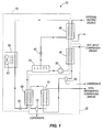
- Fig. 1 is a schematic illustration of an integrated absorption refrigeration and dehumidification system embodying the invention.
- Fig. 2 is a schematic illustration of the integrated absorption refrigeration and dehumidification system of Fig. 1 including a multi-stage compressor.
- Fig. 3 is a schematic illustration of the integrated absorption refrigeration and dehumidification system of Fig. 1 including an oil separator.
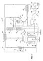
- Fig. 4 is a schematic illustration of the integrated absorption refrigeration and dehumidification system of Fig. 1 including a microturbine engine.
- Fig. 1 is a schematic of an integrated absorption refrigeration and dehumidification system 10.
- the system 10 is termed "integrated" in that a single system includes both an absorption refrigeration system 15 and a dehumidification system 20.
- refrigerant in the absorption refrigeration system 15 acts on a compressed fluid in the dehumidification system 20 to remove heat from and condense water vapor in the compressed fluid.
- the compressed fluid in the dehumidification system 20 acts on an absorption solution in the absorption refrigeration cycle to separate the refrigerant from a secondary solution.
- the absorption refrigeration system 15 includes an absorber 25, a pump 30, an after-cooler or generator 35, a control valve 40, an auxiliary heater 45, a condenser 50, an expansion valve 55, and an evaporator 60.
- An absorption solution flows through the absorption refrigeration system 15 to provide cooling for compressed air.
- the absorption solution includes a soluble substance, or refrigerant, such as ammonia and a secondary solution, or absorber, such as water. In other constructions, different refrigerants and/or secondary fluids may be used to form a suitable absorption solution.
- the pump 30 is positioned downstream from the absorber 25 and draws the absorption solution from the absorber 25.
- the pump 30 may be a mechanical vacuum pump suitable to create a driving pressure.
- the pump 30 may be a lightweight gas such as, for example, hydrogen that can be heated to create a driving pressure. The gas expands as it is heated, creating the driving pressure to push the absorption solution through the refrigeration system 15.
- the after-cooler 35 and the auxiliary heater 45 are positioned downstream of the pump 30 and heat the absorption solution to facilitate separation of the refrigerant from the secondary solution.
- the after-cooler 35 and the auxiliary heater 45 may be any type of suitable heat exchanger such as, but not limited to, parallel-flow or counter-flow heat exchangers.
- the auxiliary heater 45 may be omitted or may only be used when the absorption solution is not sufficiently heated by the after-cooler 35.
- the control valve 40 is a high-to-low pressure device positioned between the auxiliary heater 45 and the absorber 25.
- the control valve 40 reduces the pressure of fluid flowing from the auxiliary heater 45 to the absorber 25.
- the control valve 40 reduces the pressure of the secondary solution after the refrigerant boils away in the auxiliary heater 45.
- the control valve 40 may be, for example, a ball valve, needle valve, check valve, or the like. As the absorption solution separates, the refrigerant vapor flows to the condenser 50 while the liquid secondary solution is directed toward the absorber 25.
- the condenser 50 is positioned between the auxiliary heater 45 and the expansion valve 55 to cool the refrigerant to a suitable temperature.
- the condenser 50 may be, for example, an air-cooled condenser or a water-cooled condenser.
- the condenser 50 is air-cooled and includes a fan 62 to propel air over a condenser coil, thereby cooling and condensing refrigerant within the coil.
- the expansion valve 55 is positioned between the condenser 50 and the evaporator 60.
- the expansion valve 55 controls the rate at which liquid refrigerant can flow toward the evaporator 60. As the liquid refrigerant passes through the expansion valve 55, the liquid refrigerant expands, thereby reducing the temperature of the refrigerant.
- the evaporator 60 is positioned between the expansion valve 55 and the absorber 25.
- the evaporator 60 includes a hot side and a cold side in a heat exchange relationship with each other such that heat from a fluid passing through the hot side may transfer to fluid passing through the cold side.
- the evaporator 60 may be, but is not limited to, a parallel-flow or counter-flow heat exchanger.
- the refrigerant from the expansion valve 55 passes through the cold side of the evaporator 60 while compressed air passes through the hot side.
- the dehumidification system 20 includes the after-cooler 35, a first separator 65, a recuperator 70, the evaporator 60, and a second separator 75.
- Humid, compressed fluid e.g., air
- the compressed fluid passes through the after-cooler 35 to cool, flows through the first separator 65 to remove condensate, and passes through the recuperator 70 and the evaporator 60 to further cool.
- the compressed fluid flows through the second separator 75 to remove more condensate and passes through the recuperator 70 a second time to facilitate cooling of the compressed fluid passing through the recuperator 70 the first time.
- the compressed fluid may be generated by a compressor such as, for example, a centrifugal compressor, a screw compressor, a reciprocating compressor, or the like.
- the first and second separators 65, 75 are positioned to remove condensate from the compressed fluid.
- the separators 65, 75 may be any type of suitable condensate separator such as, for example, a gravity separator, a filter separator, a centrifugal separator, or the like.
- the separators 65, 75 separate and remove condensed water from compressed air in order to dehumidify the compressed air.
- the separators 65, 75 may be configured to remove other fluids (e.g., oil, lubricants, etc.) from the compressed air.
- an absorption solution is drawn from the absorber 25 by the pump 30 and directed through the after-cooler 35 where heat is transferred from the hot compressed air to the absorption solution.
- the absorption solution also passes through the auxiliary heater 45 which is heated by an external heat source to further heat the absorption solution.
- the refrigerant boils away from the secondary solution, leaving a weak liquid solution (e.g., a solution composed mostly of the secondary solution) and pure refrigerant vapor (e.g., refrigerant with little or no secondary solution).
- the vaporized refrigerant flows from the auxiliary heater 45 to the condenser 50 where it is cooled and condensed to become a liquid. Liquid refrigerant leaves the condenser 50 and passes through the expansion valve 55 where the refrigerant rapidly expands, thereby producing a pressure drop and a temperature drop. The cool, low pressure refrigerant then flows to the evaporator 60 where it absorbs heat and vaporizes. The vaporized refrigerant then returns to the absorber 25 to complete the cycle.
- the weak solution flows through the control valve 40 back to the absorber 25.
- the weak solution mixes with the refrigerant, causing the weak solution to absorb the refrigerant and recreate the absorption solution.
- the absorption solution is drawn from the absorber 25 by the pump 30, increasing the pressure of the absorption solution and directing the absorption solution back toward the after-cooler 35 to begin the cycle again.
- hot, moist compressed air from a compressor flows through the after-cooler 35 to exchange heat with the absorption solution, as discussed above. Exchanging heat with the absorption solution cools the compressed air and causes some water vapor to condense.
- the first separator 65 separates and removes the condensate from the compressed air.
- the compressed air then passes through a hot side of the recuperator 70 and is cooled by compressed air leaving the evaporator 60.
- the compressed air passes through the evaporator 60 and is cooled by the vaporized refrigerant.
- more water vapor may condense as the compressed air cools.
- the second separator 75 separates and removes the additional condensate from the compressed air.
- the compressed air then passes through a cold side of the recuperator 70 where it is heated by the compressed air passing through the hot side.
- the compressed air passing through the cold side is warmed to a temperature above its dewpoint, thereby decreasing its relative humidity.
- Cool, dehumidified compressed air flows out of the dehumidification system 20 for use by a downstream air tool, system, or process. Removing water from the compressed air to reduce the relative humidity of the compressed air reduces corrosion formation and contamination of the downstream air system that receives and uses the compressed air.
- Fig. 2 illustrates the integrated absorption refrigeration and dehumidification system 10 shown in Fig. 1 , where the external heating source is provided by a multi-stage compressor.
- the auxiliary heater 45 is positioned between a first compression stage 90 and a second compression stage 95, and the after-cooler 35 is positioned after the second compression stage 95.
- compressed fluid from the first stage 90 passes through the auxiliary heater 45, and is then directed to the second stage 95 for further compression.
- the further compressed fluid from the second stage 95 is driven through the dehumidification system 20 in the manner described above with reference to Fig. 1 . This arrangement improves the efficiency of both the compressor system and the absorption refrigeration system 10.
- Fig. 3 illustrates the integrated absorption refrigeration and dehumidification system 10 shown in Fig. 1 , where the external heating source is provided by hot oil.
- the auxiliary heater 45 is in communication with an air/oil separator 110.
- compressed air and oil from a compressor 115 enter the separator 110 and undergo a cyclonic motion within the separator 110.
- the air/oil separator 110 may include other separating devices such as multichamber separators, coalescing filters, or the like.
- the oil is then directed through a thermostatic oil control valve 120 which allows oil above a predetermined temperature to pass to the auxiliary heater 45 and supplement heating of the absorption solution. Cooler oil is directed through a bypass 125 and back toward the compressor 115.
- Fig. 4 illustrates the integrated absorption refrigeration and dehumidification system 10 shown in Fig. 3 , where the hot oil is provided by a fuel or gas booster 140 for a microturbine engine 145. Also, rather than drying compressed air, the dehumidification system 20 is employed to dry compressed fuel for use in the microturbine engine 145.
- the illustrated microturbine engine includes a compressor 150, a recuperator 155, a combustor 160, a turbine 165, and an electrical generator 170.
- the fuel booster compressor 140 compresses fuel (e.g., natural gas, methane, VOCs, or other low-pressure fuels) prior to combustion in the combustor 160.
- fuel e.g., natural gas, methane, VOCs, or other low-pressure fuels
- the fuel booster compressor 140 delivers a mixture of compressed fuel and oil to the gas/oil separator 110.
- the gas/oil separator 110 separates the compressed fuel from the oil and directs the oil toward the oil cooler 120.
- the compressed fuel is directed through the after-cooler 35, the separators 65, 75, the evaporator 60, and the recuperator 70 to remove moisture and/or polysiloxanes from the compressed fuel.
- air is compressed in the compressor 150 and delivered to a cool side of the recuperator 155.
- the recuperator 155 may be, for example, a counterflow plate-fin type heat exchanger.
- the compressed air is preheated within the recuperator 155 and mixed with the fuel from the fuel booster compressor 140 to create a combustible mixture.
- the combustible mixture is combusted in the combustor 160 and permitted to expand through the turbine 165, imparting rotational energy to the turbine 165.
- Rotation of the turbine 165 drives operation of the compressor 150 and the electrical generator 170 to produce electrical power at a useful frequency.
- power electronics or a gearbox may be used to condition the electrical power into a useful frequency.
- the turbine 165 and the compressor 150 are coupled for rotation together via a shaft 175.
- rotation of the turbine 165 also drives rotation of the compressor 150.
- the turbine 165 may only drive the electrical generator 170, and an additional gasifier turbine may be used to drive the compressor 150.
- the air is expanded through both the turbine 165 and the gasifier turbine.
- the air Prior to being exhausted from the microturbine engine 145, the air flows into a hot side of the recuperator 155 to preheat the inflowing compressed air.
- the gas or air flows through a waste heat generator, or auxiliary heater, 180 positioned downstream of the auxiliary heater 45 to heat the absorption solution of the refrigeration system 15, thereby supplementing the heat provided by the after-cooler 35 and the auxiliary heater 45.
- Removing moisture and polysiloxanes from the compressed fuel helps reduce unwanted flame suppression (i.e., flame-out) and helps reduce the formation of corrosive elements that can form during combustion such as, for example, an aqueous solution of H 2 S.
- condensing and removing polysiloxanes found in some fuel sources helps reduce sand formations in the combustor 160 during the combustion process.
- Integrated absorption refrigeration and dehumidification systems 10 utilize otherwise wasted heat energy from a compressor or a fuel booster to power a significant portion of the absorption refrigeration system 15, thereby improving the overall system efficiency.
- integrating the absorption refrigeration system 15 with the dehumidification system 20 reduces the physical size and cost of the inter-stage coolers (e.g., the after-cooler 35, the auxiliary heater 45, and the evaporator 60).
- Using the recuperator 70 also reduces the need for a larger refrigeration circuit and improves the overall system efficiency.
- the invention provides, among other things, an integrated absorption refrigeration and dehumidification system.
Landscapes
- Engineering & Computer Science (AREA)
- Physics & Mathematics (AREA)
- Thermal Sciences (AREA)
- Chemical & Material Sciences (AREA)
- Analytical Chemistry (AREA)
- General Chemical & Material Sciences (AREA)
- Oil, Petroleum & Natural Gas (AREA)
- Chemical Kinetics & Catalysis (AREA)
- Mechanical Engineering (AREA)
- General Engineering & Computer Science (AREA)
- Drying Of Gases (AREA)
- Sorption Type Refrigeration Machines (AREA)
Abstract
Description
- This application claims priority to
U.S. Provisional Patent Application No. 60/938,049, filed May 15, 2007 - The present invention relates to an absorption refrigeration system. More specifically, the invention relates to an integrated absorption refrigeration and dehumidification system.
- Absorption refrigeration systems follow a vapor compression cycle similar to classical refrigeration cycles. However, in an absorption refrigeration system, a refrigerant compressor typically found in a classical refrigeration cycle is replaced by a thermally-activated absorption process that requires additional thermal energy. The thermal energy separates a refrigerant from a secondary solution, making the refrigerant suitable for cooling.
- In one embodiment, the invention provides an integrated absorption refrigeration and dehumidification system including an absorber containing an absorption solution that is a mixture of a refrigerant and a secondary solution and an after-cooler having a first flow path to receive the absorption solution from the absorber and a second flow path to receive a first warm fluid. The first and second flow paths are thermally coupled such that the first warm fluid heats the absorption solution to separate a first portion of refrigerant from the absorption solution. The system also includes an auxiliary heat exchanger separate from the after-cooler and having a third flow path to receive the absorption solution from the after-cooler and a fourth flow path to receive a second warm fluid. The third and fourth flow paths are thermally coupled such that the second warm fluid heats the absorption solution to separate a second portion of refrigerant from the absorption solution. The system further includes a condenser positioned to receive the first portion of refrigerant and the second portion of refrigerant from the auxiliary heater and cool the refrigerant, an expansion valve positioned to receive the refrigerant from the condenser, and an evaporator positioned to receive a cool refrigerant from the expansion valve and the first warm fluid from the after-cooler. The evaporator is configured to cool the first warm fluid with the cool refrigerant. The system also includes a separator positioned to remove condensate from at least one of the first warm fluid from the after-cooler and a cool fluid from the evaporator.
- In another embodiment, the invention provides a dehumidification system for use with an absorption refrigeration system. The absorption refrigeration system is operable to cool a refrigerant in an absorption solution. The dehumidification system includes an after-cooler operable to receive a warm fluid. The after-cooler is configured to be in communication with a portion of the absorption refrigeration system to heat the absorption solution with the warm fluid to separate the refrigerant from a secondary solution and cool the warm fluid. The system also includes a first separator positioned to receive the warm fluid from the after-cooler and remove condensate from the warm fluid, and an evaporator positioned to receive the warm fluid from the first separator. The evaporator is configured to be in communication with a portion of the absorption refrigeration system to cool the warm fluid with the refrigerant. The system further includes a second separator separate from the first separator and positioned to receive a cool fluid from the evaporator and remove condensate from the cool fluid.
- In yet another embodiment, the invention provides a system including a microturbine engine having a compressor operable to compress air, a recuperator positioned to receive compressed air from the compressor and preheat the compressed air, and a combustor positioned to receive the compressed air from the recuperator. The combustor is operable to combust a mixture of the compressed air and a compressed fuel to produce a flow of products of combustion. The microturbine engine also includes a turbine driven by the flow of products of combustion and an electrical generator coupled to the turbine. The electrical generator is driven by the turbine to output electrical power. The system also includes an integrated absorption refrigeration and dehumidification system operable to cool and dehumidify the compressed fuel and having an absorber containing an absorption solution that is a mixture of a refrigerant and a secondary solution, and an after-cooler including a first flow path to receive the absorption solution from the absorber and a second flow path to receive a warm compressed fuel. The first and second flow paths are thermally coupled such that the warm compressed fuel heats the absorption solution to separate the refrigerant from the absorption solution. The integrated absorption refrigeration and dehumidification system also includes a condenser positioned to receive the refrigerant from the after-cooler and cool the refrigerant, an expansion valve positioned to receive the refrigerant from the condenser, and an evaporator positioned to receive a cool refrigerant from the expansion valve and the warm compressed fuel from the after-cooler. The evaporator is configured to cool the warm compressed fuel with the cool refrigerant. The integrated absorption refrigeration and dehumidification system further includes a separator positioned to remove condensate from the compressed fuel before the compressed fuel flows into the combustor of the microturbine engine.
- Other aspects of the invention will become apparent by consideration of the detailed description and accompanying drawings.
-
Fig. 1 is a schematic illustration of an integrated absorption refrigeration and dehumidification system embodying the invention. -
Fig. 2 is a schematic illustration of the integrated absorption refrigeration and dehumidification system ofFig. 1 including a multi-stage compressor. -
Fig. 3 is a schematic illustration of the integrated absorption refrigeration and dehumidification system ofFig. 1 including an oil separator. -
Fig. 4 is a schematic illustration of the integrated absorption refrigeration and dehumidification system ofFig. 1 including a microturbine engine. - Before any embodiments of the invention are explained in detail, it is to be understood that the invention is not limited in its application to the details of construction and the arrangement of components set forth in the following description or illustrated in the following drawings. The invention is capable of other embodiments and of being practiced or of being carried out in various ways. Also, it is to be understood that the phraseology and terminology used herein are for the purpose of description and should not be regarded as limiting. The use of "including," "comprising," or "having" and variations thereof herein is meant to encompass the items listed thereafter and equivalents thereof as well as additional items. Unless specified or limited otherwise, the terms "mounted," "connected," "supported," and "coupled" and variations thereof are used broadly and encompass both direct and indirect mountings, connections, supports, and couplings. Further, "connected" and "coupled" are not restricted to physical or mechanical connections or couplings.
-
Fig. 1 is a schematic of an integrated absorption refrigeration anddehumidification system 10. Thesystem 10 is termed "integrated" in that a single system includes both anabsorption refrigeration system 15 and adehumidification system 20. Generally, refrigerant in theabsorption refrigeration system 15 acts on a compressed fluid in thedehumidification system 20 to remove heat from and condense water vapor in the compressed fluid. In turn, the compressed fluid in thedehumidification system 20 acts on an absorption solution in the absorption refrigeration cycle to separate the refrigerant from a secondary solution. - In the construction illustrated in
Fig. 1 , theabsorption refrigeration system 15 includes anabsorber 25, apump 30, an after-cooler orgenerator 35, acontrol valve 40, anauxiliary heater 45, acondenser 50, anexpansion valve 55, and anevaporator 60. An absorption solution flows through theabsorption refrigeration system 15 to provide cooling for compressed air. The absorption solution includes a soluble substance, or refrigerant, such as ammonia and a secondary solution, or absorber, such as water. In other constructions, different refrigerants and/or secondary fluids may be used to form a suitable absorption solution. - The
pump 30 is positioned downstream from theabsorber 25 and draws the absorption solution from theabsorber 25. In some constructions, thepump 30 may be a mechanical vacuum pump suitable to create a driving pressure. In other constructions, thepump 30 may be a lightweight gas such as, for example, hydrogen that can be heated to create a driving pressure. The gas expands as it is heated, creating the driving pressure to push the absorption solution through therefrigeration system 15. - The after-
cooler 35 and theauxiliary heater 45 are positioned downstream of thepump 30 and heat the absorption solution to facilitate separation of the refrigerant from the secondary solution. The after-cooler 35 and theauxiliary heater 45 may be any type of suitable heat exchanger such as, but not limited to, parallel-flow or counter-flow heat exchangers. In some constructions, theauxiliary heater 45 may be omitted or may only be used when the absorption solution is not sufficiently heated by the after-cooler 35. - The
control valve 40 is a high-to-low pressure device positioned between theauxiliary heater 45 and the absorber 25. Thecontrol valve 40 reduces the pressure of fluid flowing from theauxiliary heater 45 to theabsorber 25. In the illustrated construction, thecontrol valve 40 reduces the pressure of the secondary solution after the refrigerant boils away in theauxiliary heater 45. In some constructions, thecontrol valve 40 may be, for example, a ball valve, needle valve, check valve, or the like. As the absorption solution separates, the refrigerant vapor flows to thecondenser 50 while the liquid secondary solution is directed toward theabsorber 25. - The
condenser 50 is positioned between theauxiliary heater 45 and theexpansion valve 55 to cool the refrigerant to a suitable temperature. Thecondenser 50 may be, for example, an air-cooled condenser or a water-cooled condenser. In the illustrated construction, thecondenser 50 is air-cooled and includes afan 62 to propel air over a condenser coil, thereby cooling and condensing refrigerant within the coil. - The
expansion valve 55 is positioned between thecondenser 50 and theevaporator 60. Theexpansion valve 55 controls the rate at which liquid refrigerant can flow toward theevaporator 60. As the liquid refrigerant passes through theexpansion valve 55, the liquid refrigerant expands, thereby reducing the temperature of the refrigerant. - The
evaporator 60 is positioned between theexpansion valve 55 and theabsorber 25. Theevaporator 60 includes a hot side and a cold side in a heat exchange relationship with each other such that heat from a fluid passing through the hot side may transfer to fluid passing through the cold side. For example, similar to the after-cooler 35 and theauxiliary heater 45, theevaporator 60 may be, but is not limited to, a parallel-flow or counter-flow heat exchanger. In the illustrated construction, the refrigerant from theexpansion valve 55 passes through the cold side of theevaporator 60 while compressed air passes through the hot side. - In the construction illustrated in
Fig. 1 , thedehumidification system 20 includes the after-cooler 35, afirst separator 65, arecuperator 70, theevaporator 60, and asecond separator 75. Humid, compressed fluid (e.g., air) flows through thedehumidification system 20 in order to remove water and/or heat from the compressed fluid. The compressed fluid passes through the after-cooler 35 to cool, flows through thefirst separator 65 to remove condensate, and passes through therecuperator 70 and theevaporator 60 to further cool. In addition, the compressed fluid flows through thesecond separator 75 to remove more condensate and passes through the recuperator 70 a second time to facilitate cooling of the compressed fluid passing through therecuperator 70 the first time. In some constructions, the compressed fluid may be generated by a compressor such as, for example, a centrifugal compressor, a screw compressor, a reciprocating compressor, or the like. - The first and
second separators separators separators separators - In operation of the
absorption refrigeration system 15, an absorption solution is drawn from theabsorber 25 by thepump 30 and directed through the after-cooler 35 where heat is transferred from the hot compressed air to the absorption solution. In the illustrated construction, the absorption solution also passes through theauxiliary heater 45 which is heated by an external heat source to further heat the absorption solution. As the absorption solution heats up, the refrigerant boils away from the secondary solution, leaving a weak liquid solution (e.g., a solution composed mostly of the secondary solution) and pure refrigerant vapor (e.g., refrigerant with little or no secondary solution). - The vaporized refrigerant flows from the
auxiliary heater 45 to thecondenser 50 where it is cooled and condensed to become a liquid. Liquid refrigerant leaves thecondenser 50 and passes through theexpansion valve 55 where the refrigerant rapidly expands, thereby producing a pressure drop and a temperature drop. The cool, low pressure refrigerant then flows to theevaporator 60 where it absorbs heat and vaporizes. The vaporized refrigerant then returns to theabsorber 25 to complete the cycle. - Meanwhile, the weak solution flows through the
control valve 40 back to theabsorber 25. In theabsorber 25, the weak solution mixes with the refrigerant, causing the weak solution to absorb the refrigerant and recreate the absorption solution. The absorption solution is drawn from theabsorber 25 by thepump 30, increasing the pressure of the absorption solution and directing the absorption solution back toward the after-cooler 35 to begin the cycle again. - In operation of the
dehumidification system 20, hot, moist compressed air from a compressor flows through the after-cooler 35 to exchange heat with the absorption solution, as discussed above. Exchanging heat with the absorption solution cools the compressed air and causes some water vapor to condense. Thefirst separator 65 separates and removes the condensate from the compressed air. - The compressed air then passes through a hot side of the
recuperator 70 and is cooled by compressed air leaving theevaporator 60. - Next, the compressed air passes through the
evaporator 60 and is cooled by the vaporized refrigerant. In theevaporator 60, more water vapor may condense as the compressed air cools. Thesecond separator 75 separates and removes the additional condensate from the compressed air. - The compressed air then passes through a cold side of the
recuperator 70 where it is heated by the compressed air passing through the hot side. In therecuperator 70, the compressed air passing through the cold side is warmed to a temperature above its dewpoint, thereby decreasing its relative humidity. Cool, dehumidified compressed air flows out of thedehumidification system 20 for use by a downstream air tool, system, or process. Removing water from the compressed air to reduce the relative humidity of the compressed air reduces corrosion formation and contamination of the downstream air system that receives and uses the compressed air. -
Fig. 2 illustrates the integrated absorption refrigeration anddehumidification system 10 shown inFig. 1 , where the external heating source is provided by a multi-stage compressor. For example, as shown in the construction illustrated inFig. 2 , theauxiliary heater 45 is positioned between afirst compression stage 90 and asecond compression stage 95, and the after-cooler 35 is positioned after thesecond compression stage 95. - In operation, compressed fluid from the
first stage 90 passes through theauxiliary heater 45, and is then directed to thesecond stage 95 for further compression. The further compressed fluid from thesecond stage 95 is driven through thedehumidification system 20 in the manner described above with reference toFig. 1 . This arrangement improves the efficiency of both the compressor system and theabsorption refrigeration system 10. -
Fig. 3 illustrates the integrated absorption refrigeration anddehumidification system 10 shown inFig. 1 , where the external heating source is provided by hot oil. For example, as shown in the construction illustrated inFig. 3 , theauxiliary heater 45 is in communication with an air/oil separator 110. In one arrangement, compressed air and oil from a compressor 115 (e.g., an oil-flooded rotary screw compressor) enter theseparator 110 and undergo a cyclonic motion within theseparator 110. As the compressed air and the oil are whirled around an inner surface of theseparator 110, the heavy oil is forced outward and slides down the inner surface to collect in the bottom of theseparator 110, thereby separating the compressed air and the oil. In other arrangements, the air/oil separator 110 may include other separating devices such as multichamber separators, coalescing filters, or the like. - The oil is then directed through a thermostatic
oil control valve 120 which allows oil above a predetermined temperature to pass to theauxiliary heater 45 and supplement heating of the absorption solution. Cooler oil is directed through abypass 125 and back toward thecompressor 115. -
Fig. 4 illustrates the integrated absorption refrigeration anddehumidification system 10 shown inFig. 3 , where the hot oil is provided by a fuel orgas booster 140 for amicroturbine engine 145. Also, rather than drying compressed air, thedehumidification system 20 is employed to dry compressed fuel for use in themicroturbine engine 145. The illustrated microturbine engine includes acompressor 150, arecuperator 155, acombustor 160, aturbine 165, and anelectrical generator 170. - The
fuel booster compressor 140 compresses fuel (e.g., natural gas, methane, VOCs, or other low-pressure fuels) prior to combustion in thecombustor 160. In the illustrated construction, thefuel booster compressor 140 delivers a mixture of compressed fuel and oil to the gas/oil separator 110. The gas/oil separator 110 separates the compressed fuel from the oil and directs the oil toward theoil cooler 120. The compressed fuel is directed through the after-cooler 35, theseparators evaporator 60, and therecuperator 70 to remove moisture and/or polysiloxanes from the compressed fuel. - In operation of the
microturbine engine 145, air is compressed in thecompressor 150 and delivered to a cool side of therecuperator 155. Therecuperator 155 may be, for example, a counterflow plate-fin type heat exchanger. The compressed air is preheated within therecuperator 155 and mixed with the fuel from thefuel booster compressor 140 to create a combustible mixture. The combustible mixture is combusted in thecombustor 160 and permitted to expand through theturbine 165, imparting rotational energy to theturbine 165. Rotation of theturbine 165 drives operation of thecompressor 150 and theelectrical generator 170 to produce electrical power at a useful frequency. In some embodiments, power electronics or a gearbox may be used to condition the electrical power into a useful frequency. - In the illustrated
microturbine engine 145, theturbine 165 and thecompressor 150 are coupled for rotation together via ashaft 175. Thus, rotation of theturbine 165 also drives rotation of thecompressor 150. In other embodiments, theturbine 165 may only drive theelectrical generator 170, and an additional gasifier turbine may be used to drive thecompressor 150. In such embodiments, the air is expanded through both theturbine 165 and the gasifier turbine. Prior to being exhausted from themicroturbine engine 145, the air flows into a hot side of therecuperator 155 to preheat the inflowing compressed air. In addition, the gas or air flows through a waste heat generator, or auxiliary heater, 180 positioned downstream of theauxiliary heater 45 to heat the absorption solution of therefrigeration system 15, thereby supplementing the heat provided by the after-cooler 35 and theauxiliary heater 45. - Removing moisture and polysiloxanes from the compressed fuel helps reduce unwanted flame suppression (i.e., flame-out) and helps reduce the formation of corrosive elements that can form during combustion such as, for example, an aqueous solution of H2S. In addition, condensing and removing polysiloxanes found in some fuel sources (e.g., waste gas) helps reduce sand formations in the
combustor 160 during the combustion process. - Integrated absorption refrigeration and
dehumidification systems 10 utilize otherwise wasted heat energy from a compressor or a fuel booster to power a significant portion of theabsorption refrigeration system 15, thereby improving the overall system efficiency. In addition, integrating theabsorption refrigeration system 15 with thedehumidification system 20 reduces the physical size and cost of the inter-stage coolers (e.g., the after-cooler 35, theauxiliary heater 45, and the evaporator 60). Using therecuperator 70 also reduces the need for a larger refrigeration circuit and improves the overall system efficiency. - Thus, the invention provides, among other things, an integrated absorption refrigeration and dehumidification system.
- Various features and advantages of the invention are set forth in the following claims.
Claims (20)
- An integrated absorption refrigeration and dehumidification system comprising:an absorber containing an absorption solution that is a mixture of a refrigerant and a secondary solution;an after-cooler including a first flow path to receive the absorption solution from the absorber and a second flow path to receive a first warm fluid, the first and second flow paths being thermally coupled such that the first warm fluid heats the absorption solution to separate a first portion of refrigerant from the absorption solution;an auxiliary heat exchanger separate from the after-cooler and including a third flow path to receive the absorption solution from the after-cooler and a fourth flow path to receive a second warm fluid, the third and fourth flow paths being thermally coupled such that the second warm fluid heats the absorption solution to separate a second portion of refrigerant from the absorption solution;a condenser positioned to receive the first portion of refrigerant and the second portion of refrigerant from the auxiliary heater and cool the refrigerant;an expansion valve positioned to receive the refrigerant from the condenser;an evaporator positioned to receive a cool refrigerant from the expansion valve and the first warm fluid from the after-cooler, the evaporator configured to cool the first warm fluid with the cool refrigerant to discharge a cool fluid; anda separator positioned to remove condensate from at least one of the first warm fluid from the after-cooler and the cool fluid from the evaporator.
- The integrated absorption refrigeration and dehumidification system of claim 1, further comprising a pump positioned between the absorber and the after-cooler to draw the absorption solution from the absorber and propel the absorption solution into the after-cooler.
- The integrated absorption refrigeration and dehumidification system of claim 1, further comprising a control valve positioned between the auxiliary heat exchanger and the absorber to direct the secondary solution from the auxiliary heat exchanger to the absorber.
- The integrated absorption refrigeration and dehumidification system of claim 1, wherein the separator is positioned to receive the first warm fluid from the after-cooler to remove condensate from the warm fluid, the system further comprising a second separator positioned to receive the cool fluid from the evaporator to remove condensate from the cool fluid.
- The integrated absorption refrigeration and dehumidification system of claim 1, further comprising a recuperator including a first side and a second side in a heat exchange relationship, wherein the first warm fluid from the after-cooler passes through the first side and the cool fluid from the evaporator passes through the second side.
- The integrated absorption refrigeration and dehumidification system of claim 1, wherein at least one of the first warm fluid and the second warm fluid is compressed air from a compressor.
- The integrated absorption refrigeration and dehumidification system of claim 6, wherein the compressor is a multi-stage compressor including a first stage and a second stage, and wherein compressed air from the first stage is the second warm fluid and compressed air from the second stage is the first warm fluid.
- The integrated absorption refrigeration and dehumidification system of claim 6, wherein the compressor is an oil-flooded rotary screw compressor, wherein the compressed air is separated from hot oil with an oil separator, and wherein the hot oil is the second warm fluid that passes through the fourth flow path of the auxiliary heater to heat the absorption solution and cool the hot oil in the auxiliary heater.
- The integrated absorption refrigeration and dehumidification system of claim 1, wherein the first warm fluid is compressed fuel for a microturbine engine.
- A dehumidification system for use with an absorption refrigeration system, the absorption refrigeration system operable to cool a refrigerant in an absorption solution, the dehumidification system comprising:an after-cooler configured to receive a warm fluid, the after-cooler configured to be in communication with a portion of the absorption refrigeration system to heat the absorption solution with the warm fluid to separate the refrigerant from a secondary solution and cool the warm fluid;a first separator positioned to receive the warm fluid from the after-cooler and remove condensate from the warm fluid;an evaporator positioned to receive the warm fluid from the first separator, the evaporator configured to be in communication with a portion of the absorption refrigeration system to cool the warm fluid with the refrigerant; anda second separator separate from the first separator and positioned to receive a cool fluid from the evaporator and remove condensate from the cool fluid.
- The dehumidification system of claim 10, wherein the warm fluid is compressed air from a compressor.
- The dehumidification system of claim 10, wherein the warm fluid is compressed fuel for a microturbine engine.
- The dehumidification system of claim 10, further comprising a recuperator including a first side and a second side in a heat exchange relationship, wherein the warm fluid from the first separator passes through the first side and the cool fluid from the second separator passes through the second side.
- A system comprising:a microturbine engine including
a compressor operable to compress air,
a recuperator positioned to receive compressed air from the compressor and preheat the compressed air,
a combustor positioned to receive the compressed air from the recuperator, the combustor operable to combust a mixture of the compressed air and a compressed fuel to produce a flow of products of combustion,
a turbine driven by the flow of products of combustion, and
an electrical generator coupled to the turbine, the electrical generator driven by the turbine to output electrical power; andan integrated absorption refrigeration and dehumidification system operable to cool and dehumidify the compressed fuel and including
an absorber containing an absorption solution that is a mixture of a refrigerant and a secondary solution,
an after-cooler including a first flow path to receive the absorption solution from the absorber and a second flow path to receive a warm compressed fuel, the first and second flow paths being thermally coupled such that the warm compressed fuel heats the absorption solution to separate the refrigerant from the absorption solution,
a condenser positioned to receive the refrigerant from the after-cooler and cool the refrigerant,
an expansion valve positioned to receive the refrigerant from the condenser,
an evaporator positioned to receive a cool refrigerant from the expansion valve and the warm compressed fuel from the after-cooler, the evaporator configured to cool the warm compressed fuel with the cool refrigerant, and
a separator positioned to remove condensate from the compressed fuel before the compressed fuel flows into the combustor of the microturbine engine. - The system of claim 14, further comprising a fuel booster in fluid communication with the after-cooler, wherein the fuel booster compresses a fuel into the warm compressed fuel.
- The system of claim 15, wherein the integrated absorption refrigeration and dehumidification system includes an auxiliary heater separate from the after-cooler and including a third flow path to receive the absorption solution from the after-cooler and a fourth flow path to receive a warm fluid, and wherein the third and fourth flow paths are thermally coupled such that the warm fluid heats the absorption solution to further separate the refrigerant from the absorption solution.
- The system of claim 16, further comprising an oil separator positioned between the fuel booster and the auxiliary heater, wherein the oil separator separates the compressed fuel from hot oil, and wherein the hot oil is the warm fluid that passes through the fourth flow path of the auxiliary heater to heat the absorption solution in the auxiliary heater.
- The system of claim 16, wherein the flow of products of combustion is the warm fluid, and wherein the auxiliary heater is positioned to receive the flow of products of combustion from the recuperator to heat the absorption solution in the auxiliary heater.
- The system of claim 14, wherein the integrated absorption refrigeration and dehumidification system includes a second separator positioned to receive the warm compressed fuel form the after-cooler and remove condensate from the warm compressed fuel.
- The system of claim 14, wherein the integrated absorption refrigeration and dehumidification system includes a second recuperator having a first side and a second side in a heat exchange relationship, and wherein the warm compressed fuel from the after-cooler passes through the first side and the compressed fuel from the evaporator passes through the second side before flowing into the combustor of the microturbine engine.
Applications Claiming Priority (1)
| Application Number | Priority Date | Filing Date | Title |
|---|---|---|---|
| US93804907P | 2007-05-15 | 2007-05-15 |
Publications (3)
| Publication Number | Publication Date |
|---|---|
| EP1992883A2 true EP1992883A2 (en) | 2008-11-19 |
| EP1992883A3 EP1992883A3 (en) | 2011-10-12 |
| EP1992883B1 EP1992883B1 (en) | 2014-08-20 |
Family
ID=40026138
Family Applications (1)
| Application Number | Title | Priority Date | Filing Date |
|---|---|---|---|
| EP08251666.7A Not-in-force EP1992883B1 (en) | 2007-05-15 | 2008-05-10 | Integrated absorption refrigeration and dehumidification system |
Country Status (3)
| Country | Link |
|---|---|
| US (1) | US8601825B2 (en) |
| EP (1) | EP1992883B1 (en) |
| CN (1) | CN101307965B (en) |
Cited By (4)
| Publication number | Priority date | Publication date | Assignee | Title |
|---|---|---|---|---|
| CN103316568A (en) * | 2013-06-18 | 2013-09-25 | 东莞理工学院 | A Combined Compressed Air Cryogenic Dehumidifier |
| CN104654653A (en) * | 2014-01-27 | 2015-05-27 | 李华玉 | Combined thermal dynamic system |
| CN104654652A (en) * | 2014-01-27 | 2015-05-27 | 李华玉 | Combined thermal dynamic system |
| CN107580443A (en) * | 2016-07-04 | 2018-01-12 | 香江科技股份有限公司 | A kind of data center's integrative cooling system and its control method based on waste heat recovery |
Families Citing this family (19)
| Publication number | Priority date | Publication date | Assignee | Title |
|---|---|---|---|---|
| US9470149B2 (en) * | 2008-12-11 | 2016-10-18 | General Electric Company | Turbine inlet air heat pump-type system |
| CN102140927B (en) * | 2011-04-29 | 2014-08-27 | 武汉纺织大学 | Method and system for reducing temperature locally under coal mine shaft |
| CN102226601B (en) * | 2011-06-03 | 2012-12-19 | 北京建筑工程学院 | Multifunctional injection heat pump unit |
| EP2609983A1 (en) * | 2011-12-29 | 2013-07-03 | Brunnschweiler S.A. | Method and system for processing hot humid air resulting from an industrial process,prior to expelling it into the outside air, to recover water and remove the plume |
| CN102563684A (en) * | 2012-01-12 | 2012-07-11 | 亿恒节能科技江苏有限公司 | Fuel gas circulated tail gas refrigerating fuel gas air independent dehumidification heating system |
| EP2964911B1 (en) | 2013-03-04 | 2022-02-23 | Echogen Power Systems LLC | Heat engine systems with high net power supercritical carbon dioxide circuits |
| CN103344062B (en) * | 2013-07-16 | 2015-05-20 | 祥天控股(集团)有限公司 | High-pressure cooling air storage device |
| US9874112B2 (en) * | 2013-09-05 | 2018-01-23 | Echogen Power Systems, Llc | Heat engine system having a selectively configurable working fluid circuit |
| WO2015034988A1 (en) * | 2013-09-05 | 2015-03-12 | Echogen Power Systems, L.L.C. | Control methods for heat engine systems having a selectively configurable working fluid circuit |
| US10570777B2 (en) | 2014-11-03 | 2020-02-25 | Echogen Power Systems, Llc | Active thrust management of a turbopump within a supercritical working fluid circuit in a heat engine system |
| US20160146516A1 (en) * | 2014-11-23 | 2016-05-26 | Mingsheng Liu | Absorption Cooling Air Compressor System |
| CN106705186A (en) * | 2017-02-27 | 2017-05-24 | 西安热工研究院有限公司 | Lignite-based cogeneration system |
| CN108444277A (en) | 2018-03-12 | 2018-08-24 | 湖南科技大学 | The Intelligent dehumidifying device of heated air circulation roasting system |
| US11187112B2 (en) | 2018-06-27 | 2021-11-30 | Echogen Power Systems Llc | Systems and methods for generating electricity via a pumped thermal energy storage system |
| US11435120B2 (en) | 2020-05-05 | 2022-09-06 | Echogen Power Systems (Delaware), Inc. | Split expansion heat pump cycle |
| US11629638B2 (en) | 2020-12-09 | 2023-04-18 | Supercritical Storage Company, Inc. | Three reservoir electric thermal energy storage system |
| US12516855B2 (en) | 2022-10-27 | 2026-01-06 | Supercritical Storage Company, Inc. | High-temperature, dual rail heat pump cycle for high performance at high-temperature lift and range |
| WO2025010090A1 (en) | 2023-02-07 | 2025-01-09 | Supercritical Storage Company, Inc. | Waste heat integration into pumped thermal energy storage |
| CN120906686B (en) * | 2025-10-13 | 2026-01-27 | 中国科学院工程热物理研究所 | Gas turbine combined cycle cold-heat-electricity-hydrogen combined supply system coupling high-temperature heat storage and phase change cold storage and operation control method thereof |
Family Cites Families (16)
| Publication number | Priority date | Publication date | Assignee | Title |
|---|---|---|---|---|
| US3739594A (en) | 1972-01-21 | 1973-06-19 | C Freese | Method and apparatus for drying compressed air |
| US4337625A (en) | 1981-03-02 | 1982-07-06 | Battelle Development Corp. | Waste heat driven absorption refrigeration process and system |
| FR2504249A1 (en) | 1981-04-15 | 1982-10-22 | Inst Francais Du Petrole | PROCESS FOR PRODUCING COLD AND / OR HEAT USING AN ABSORPTION CYCLE |
| US4819446A (en) | 1986-12-15 | 1989-04-11 | Moore Roy A | Waste heat cooling apparatus |
| DE19721351A1 (en) | 1997-05-22 | 1998-11-26 | Ees Erdgas Energiesysteme Gmbh | Process and plant for generating cold and / or heat |
| US5916252A (en) | 1997-10-29 | 1999-06-29 | Matsushita Electric Industrial Co., Ltd. | Refrigerating or air-conditioning apparatus |
| US6050082A (en) * | 1998-01-20 | 2000-04-18 | General Electric Company | Intercooled gas turbine engine with integral air bottoming cycle |
| US6128909A (en) * | 1998-06-04 | 2000-10-10 | Alliedsignal Inc. | Air cycle environmental control systems with two stage compression and expansion and separate ambient air fan |
| US6073454A (en) | 1998-07-10 | 2000-06-13 | Spauschus Associates, Inc. | Reduced pressure carbon dioxide-based refrigeration system |
| CA2391500C (en) * | 2000-03-03 | 2008-11-18 | Process Management Enterprises Ltd. | Ammonia synthesis process and apparatus for use therein |
| SE518504C2 (en) * | 2000-07-10 | 2002-10-15 | Evol Ingenjoers Ab Fa | Process and systems for power generation, as well as facilities for retrofitting in power generation systems |
| FR2830463B1 (en) | 2001-10-09 | 2004-08-06 | Air Liquide | METHOD AND APPARATUS FOR THE TREATMENT OF A GAS BY ADSORPTION, IN PARTICULAR FOR THE CLEANING OF ATMOSPHERIC AIR BEFORE SEPARATION BY DISTILLATION |
| US6931876B2 (en) | 2003-10-08 | 2005-08-23 | International Business Machines Corporation | Apparatus and method for utilizing recirculated heat to cause refrigeration |
| IL177021A0 (en) | 2006-07-23 | 2006-12-10 | Totec Ltd Top Technologies | Working fluids for an absorption cooling system |
| IL177020A0 (en) | 2006-07-23 | 2006-12-10 | Totec Ltd Top Technologies | Absorption cooling system |
| US8006503B2 (en) * | 2006-11-15 | 2011-08-30 | Ingersoll-Rand Company | Energy recovery system and method for a refrigerated dehumidification process |
-
2008
- 2008-05-08 US US12/117,068 patent/US8601825B2/en active Active
- 2008-05-10 EP EP08251666.7A patent/EP1992883B1/en not_active Not-in-force
- 2008-05-15 CN CN2008100995870A patent/CN101307965B/en active Active
Cited By (6)
| Publication number | Priority date | Publication date | Assignee | Title |
|---|---|---|---|---|
| CN103316568A (en) * | 2013-06-18 | 2013-09-25 | 东莞理工学院 | A Combined Compressed Air Cryogenic Dehumidifier |
| CN104654653A (en) * | 2014-01-27 | 2015-05-27 | 李华玉 | Combined thermal dynamic system |
| CN104654652A (en) * | 2014-01-27 | 2015-05-27 | 李华玉 | Combined thermal dynamic system |
| CN104654652B (en) * | 2014-01-27 | 2017-09-08 | 李华玉 | The dynamic co-feeding system of heat |
| CN107580443A (en) * | 2016-07-04 | 2018-01-12 | 香江科技股份有限公司 | A kind of data center's integrative cooling system and its control method based on waste heat recovery |
| CN107580443B (en) * | 2016-07-04 | 2024-01-30 | 香江科技股份有限公司 | Comprehensive cooling system of data center based on waste heat recovery and control method thereof |
Also Published As
| Publication number | Publication date |
|---|---|
| CN101307965B (en) | 2011-07-20 |
| EP1992883A3 (en) | 2011-10-12 |
| EP1992883B1 (en) | 2014-08-20 |
| CN101307965A (en) | 2008-11-19 |
| US20080282702A1 (en) | 2008-11-20 |
| US8601825B2 (en) | 2013-12-10 |
Similar Documents
| Publication | Publication Date | Title |
|---|---|---|
| US8601825B2 (en) | Integrated absorption refrigeration and dehumidification system | |
| JP5885439B2 (en) | Waste heat utilization equipment for air compressor | |
| CN102454441B (en) | Ranking cycle integrated with absorption chiller | |
| AU757764B2 (en) | Outdoor heat exchanger unit, outdoor unit, and gas heat pump type air conditioner | |
| CN101305248B (en) | System and method for transferring heat in a vapor compression circuit via a thermoelectric device | |
| US6769256B1 (en) | Power cycle and system for utilizing moderate and low temperature heat sources | |
| KR100528392B1 (en) | Vapor-compression refrigerant cycle system with refrigeration cycle and rankine cycle | |
| CN101175898B (en) | System and method for managing water content in a fluid | |
| US20110088399A1 (en) | Combined Cycle Power Plant Including A Refrigeration Cycle | |
| EP2196651A2 (en) | Low grade heat recovery system for turbine air inlet | |
| CN107031339A (en) | Air conditioning system of a motor vehicle and method for operating the air conditioning system | |
| JPH11270352A (en) | Inlet-cooled gas turbine power plant and combined power plant using the same | |
| CN101796355A (en) | Thermally activated high efficiency heat pump | |
| CN102345909A (en) | Desiccant air-conditioning system | |
| JP2000356431A (en) | Method and apparatus for converting low-grade heat to cooling load in an integrated gasification system | |
| WO1999022186A1 (en) | Method of refrigeration purification and power generation of industrial waste gas and apparatus therefor | |
| CN105143788B (en) | Combine vapor adsorption and mechanical compress cyclic design | |
| CN101586482B (en) | Low-temperature engine and engine heat regeneration method | |
| US6457315B1 (en) | Hybrid refrigeration cycle for combustion turbine inlet air cooling | |
| RU2467190C2 (en) | System of fuel compression/conditioning for gas conditioning, method of gas conditioning and micro turbine engine | |
| EP1843108B1 (en) | Air refrigerant type refrigerating/heating apparatus | |
| CN113272527A (en) | Heat pump system and district heating network comprising a heat pump system | |
| JP2005315127A (en) | Gas turbine | |
| JP2019094808A (en) | Gas turbine system | |
| KR19990078168A (en) | Absorption refrigeration system with condensate solution coupling |
Legal Events
| Date | Code | Title | Description |
|---|---|---|---|
| PUAI | Public reference made under article 153(3) epc to a published international application that has entered the european phase |
Free format text: ORIGINAL CODE: 0009012 |
|
| AK | Designated contracting states |
Kind code of ref document: A2 Designated state(s): AT BE BG CH CY CZ DE DK EE ES FI FR GB GR HR HU IE IS IT LI LT LU LV MC MT NL NO PL PT RO SE SI SK TR |
|
| AX | Request for extension of the european patent |
Extension state: AL BA MK RS |
|
| PUAL | Search report despatched |
Free format text: ORIGINAL CODE: 0009013 |
|
| AK | Designated contracting states |
Kind code of ref document: A3 Designated state(s): AT BE BG CH CY CZ DE DK EE ES FI FR GB GR HR HU IE IS IT LI LT LU LV MC MT NL NO PL PT RO SE SI SK TR |
|
| AX | Request for extension of the european patent |
Extension state: AL BA MK RS |
|
| RIC1 | Information provided on ipc code assigned before grant |
Ipc: F24F 3/14 20060101AFI20110907BHEP |
|
| 17P | Request for examination filed |
Effective date: 20120319 |
|
| AKX | Designation fees paid |
Designated state(s): DE ES FR GB IT |
|
| REG | Reference to a national code |
Ref country code: DE Ref legal event code: R079 Ref document number: 602008033946 Country of ref document: DE Free format text: PREVIOUS MAIN CLASS: F24F0003140000 Ipc: B01D0053260000 |
|
| GRAP | Despatch of communication of intention to grant a patent |
Free format text: ORIGINAL CODE: EPIDOSNIGR1 |
|
| RIC1 | Information provided on ipc code assigned before grant |
Ipc: F25B 15/02 20060101ALI20140314BHEP Ipc: B01D 53/26 20060101AFI20140314BHEP |
|
| INTG | Intention to grant announced |
Effective date: 20140424 |
|
| GRAS | Grant fee paid |
Free format text: ORIGINAL CODE: EPIDOSNIGR3 |
|
| GRAA | (expected) grant |
Free format text: ORIGINAL CODE: 0009210 |
|
| AK | Designated contracting states |
Kind code of ref document: B1 Designated state(s): DE ES FR GB IT |
|
| REG | Reference to a national code |
Ref country code: GB Ref legal event code: FG4D |
|
| REG | Reference to a national code |
Ref country code: DE Ref legal event code: R096 Ref document number: 602008033946 Country of ref document: DE Effective date: 20141002 |
|
| PG25 | Lapsed in a contracting state [announced via postgrant information from national office to epo] |
Ref country code: ES Free format text: LAPSE BECAUSE OF FAILURE TO SUBMIT A TRANSLATION OF THE DESCRIPTION OR TO PAY THE FEE WITHIN THE PRESCRIBED TIME-LIMIT Effective date: 20140820 |
|
| REG | Reference to a national code |
Ref country code: DE Ref legal event code: R097 Ref document number: 602008033946 Country of ref document: DE |
|
| PLBE | No opposition filed within time limit |
Free format text: ORIGINAL CODE: 0009261 |
|
| STAA | Information on the status of an ep patent application or granted ep patent |
Free format text: STATUS: NO OPPOSITION FILED WITHIN TIME LIMIT |
|
| 26N | No opposition filed |
Effective date: 20150521 |
|
| REG | Reference to a national code |
Ref country code: FR Ref legal event code: PLFP Year of fee payment: 8 |
|
| PGFP | Annual fee paid to national office [announced via postgrant information from national office to epo] |
Ref country code: DE Payment date: 20150805 Year of fee payment: 8 Ref country code: GB Payment date: 20150805 Year of fee payment: 8 |
|
| PGFP | Annual fee paid to national office [announced via postgrant information from national office to epo] |
Ref country code: FR Payment date: 20150805 Year of fee payment: 8 |
|
| PGFP | Annual fee paid to national office [announced via postgrant information from national office to epo] |
Ref country code: IT Payment date: 20150806 Year of fee payment: 8 |
|
| REG | Reference to a national code |
Ref country code: DE Ref legal event code: R119 Ref document number: 602008033946 Country of ref document: DE |
|
| GBPC | Gb: european patent ceased through non-payment of renewal fee |
Effective date: 20160510 |
|
| PG25 | Lapsed in a contracting state [announced via postgrant information from national office to epo] |
Ref country code: IT Free format text: LAPSE BECAUSE OF NON-PAYMENT OF DUE FEES Effective date: 20160510 |
|
| REG | Reference to a national code |
Ref country code: FR Ref legal event code: ST Effective date: 20170131 |
|
| PG25 | Lapsed in a contracting state [announced via postgrant information from national office to epo] |
Ref country code: FR Free format text: LAPSE BECAUSE OF NON-PAYMENT OF DUE FEES Effective date: 20160531 Ref country code: DE Free format text: LAPSE BECAUSE OF NON-PAYMENT OF DUE FEES Effective date: 20161201 |
|
| PG25 | Lapsed in a contracting state [announced via postgrant information from national office to epo] |
Ref country code: GB Free format text: LAPSE BECAUSE OF NON-PAYMENT OF DUE FEES Effective date: 20160510 |