EP1992797A2 - Integrated acoustic damper with thin sheet insert - Google Patents
Integrated acoustic damper with thin sheet insert Download PDFInfo
- Publication number
- EP1992797A2 EP1992797A2 EP08156054A EP08156054A EP1992797A2 EP 1992797 A2 EP1992797 A2 EP 1992797A2 EP 08156054 A EP08156054 A EP 08156054A EP 08156054 A EP08156054 A EP 08156054A EP 1992797 A2 EP1992797 A2 EP 1992797A2
- Authority
- EP
- European Patent Office
- Prior art keywords
- cavity
- insert
- conduit
- noise damper
- compressor
- Prior art date
- Legal status (The legal status is an assumption and is not a legal conclusion. Google has not performed a legal analysis and makes no representation as to the accuracy of the status listed.)
- Granted
Links
- 238000000034 method Methods 0.000 claims description 14
- 230000007704 transition Effects 0.000 claims description 4
- 238000005266 casting Methods 0.000 claims description 3
- 239000002131 composite material Substances 0.000 claims description 2
- 238000004519 manufacturing process Methods 0.000 claims description 2
- 239000000463 material Substances 0.000 claims description 2
- 239000002184 metal Substances 0.000 claims description 2
- 229910052751 metal Inorganic materials 0.000 claims description 2
- 229920003023 plastic Polymers 0.000 claims description 2
- 239000004033 plastic Substances 0.000 claims description 2
- 238000010276 construction Methods 0.000 claims 1
- 150000002739 metals Chemical class 0.000 claims 1
- 238000005516 engineering process Methods 0.000 abstract description 5
- 239000007789 gas Substances 0.000 description 16
- 230000004323 axial length Effects 0.000 description 6
- 238000002485 combustion reaction Methods 0.000 description 5
- 238000013016 damping Methods 0.000 description 3
- 239000000567 combustion gas Substances 0.000 description 2
- 239000000446 fuel Substances 0.000 description 2
- 238000009434 installation Methods 0.000 description 2
- 230000007246 mechanism Effects 0.000 description 2
- 239000012858 resilient material Substances 0.000 description 2
- 230000008859 change Effects 0.000 description 1
- 230000001627 detrimental effect Effects 0.000 description 1
- 238000010586 diagram Methods 0.000 description 1
- 238000003780 insertion Methods 0.000 description 1
- 230000037431 insertion Effects 0.000 description 1
- 238000007689 inspection Methods 0.000 description 1
- 238000003754 machining Methods 0.000 description 1
- 230000008569 process Effects 0.000 description 1
- 230000009467 reduction Effects 0.000 description 1
- 238000000926 separation method Methods 0.000 description 1
- 239000013598 vector Substances 0.000 description 1
Images


Classifications
-
- F—MECHANICAL ENGINEERING; LIGHTING; HEATING; WEAPONS; BLASTING
- F02—COMBUSTION ENGINES; HOT-GAS OR COMBUSTION-PRODUCT ENGINE PLANTS
- F02M—SUPPLYING COMBUSTION ENGINES IN GENERAL WITH COMBUSTIBLE MIXTURES OR CONSTITUENTS THEREOF
- F02M35/00—Combustion-air cleaners, air intakes, intake silencers, or induction systems specially adapted for, or arranged on, internal-combustion engines
- F02M35/12—Intake silencers ; Sound modulation, transmission or amplification
- F02M35/1272—Intake silencers ; Sound modulation, transmission or amplification using absorbing, damping, insulating or reflecting materials, e.g. porous foams, fibres, rubbers, fabrics, coatings or membranes
-
- F—MECHANICAL ENGINEERING; LIGHTING; HEATING; WEAPONS; BLASTING
- F02—COMBUSTION ENGINES; HOT-GAS OR COMBUSTION-PRODUCT ENGINE PLANTS
- F02M—SUPPLYING COMBUSTION ENGINES IN GENERAL WITH COMBUSTIBLE MIXTURES OR CONSTITUENTS THEREOF
- F02M35/00—Combustion-air cleaners, air intakes, intake silencers, or induction systems specially adapted for, or arranged on, internal-combustion engines
- F02M35/12—Intake silencers ; Sound modulation, transmission or amplification
- F02M35/1277—Reinforcement of walls, e.g. with ribs or laminates; Walls having air gaps or additional sound damping layers
Definitions
- Subject matter disclosed herein relates generally to systems that include a compressor for intake air for an internal combustion engine.
- Turbochargers produce aerodynamic noises that can annoy vehicle passengers as well as those in the surrounding environment. Such noises can propagate to other engine system components where acoustic energy may be detrimental and increase wear. In general, most people view turbocharger noise as a nuisance.
- the intake air compressor and the exhaust turbine generate noise.
- Characteristics of generated noise typically change with operating conditions. For example, as a compressor moves toward surge (a non-optimal operating condition), noise generation can intensify due to flow separation at the suction side of the compressor blades. This noise can propagate through the high density compressed air as well as through structures connected to the compressor.
- turbocharger noise can lead to complaints
- noise can also provide information as to particular issues associated with turbocharging (e.g., compressor wheel imbalance, etc.).
- turbocharging e.g., compressor wheel imbalance, etc.
- most noise complaints are determined to be associated with normal turbocharger operation.
- techniques that reduce turbocharger noise have the potential to reduce not only complaints but also unwarranted service calls.
- An exemplary noise damper for a compressor of a turbocharger includes a compressor housing comprising a cavity substantially adjacent a gas flow surface of a conduit to a compressed gas outlet of the compressor housing and an insert that spans the cavity and forms a wall of the cavity where the wall includes one or more openings to the cavity to thereby allow acoustic energy to be damped by the cavity.
- a compressor housing comprising a cavity substantially adjacent a gas flow surface of a conduit to a compressed gas outlet of the compressor housing and an insert that spans the cavity and forms a wall of the cavity where the wall includes one or more openings to the cavity to thereby allow acoustic energy to be damped by the cavity.
- Fig. 1 is a diagram of a conventional engine and turbocharger.
- Fig. 2 is a perspective view of an exemplary compressor unit that includes a noise damper.
- Fig. 3 is an exploded, perspective view of an exemplary noise damper for use with a compressor.
- Fig. 4 is a series of cross-sectional views of the exemplary noise damper of Fig. 3 .
- Fig. 5 is a series of cross-sectional views for noise dampers having various insert configurations.
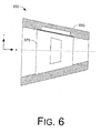
- Fig. 6 is a cross-sectional view of a noise damper that has a varying conduit cross-sectional flow area (e.g., diameter) along a length of the conduit.
- turbochargers are frequently utilized to increase the output of an internal combustion engine.
- a turbocharger generally acts to extract energy from the exhaust gas and to provide energy to intake air, which may be combined with fuel to form combustion gas.
- a prior art system 100 including an internal combustion engine 110 and a turbocharger 120 is shown.
- the internal combustion engine 110 includes an engine block 118 housing one or more combustion chambers that operatively drive a shaft 112.
- an intake port 114 provides a flow path for air to the engine block 118 while an exhaust port 116 provides a flow path for exhaust from the engine block 118.
- the turbocharger 120 acts to extract energy from the exhaust and to provide energy to intake air, which may be combined with fuel to form combustion gas.
- the turbocharger 120 includes an air inlet 134, a shaft 122, a compressor unit 124, a turbine unit 126, a housing 128 and an exhaust outlet 136.
- the housing 128 may be referred to as a center housing as it is disposed between the compressor unit 124 and the turbine unit 126.
- the shaft 122 may be a shaft assembly that includes a variety of components.
- variable geometry mechanism and variable geometry controller optionally include features such as those associated with commercially available variable geometry turbochargers (VGTs).
- VGTs include, for example, the GARRETT ® VNT TM and AVNT TM turbochargers, which use multiple adjustable vanes to control the flow of exhaust across a turbine.
- An exemplary turbocharger may employ wastegate technology as an alternative or in addition to variable geometry technology.
- turbochargers include an electric motor operably coupled to a shaft to drive a compressor using electrical energy, for example, where exhaust energy alone is insufficient to achieve a desired level of boost.
- a turbocharger may include a generator configured to generate electrical energy from exhaust gas.
- a turbocharger generates noise.
- Fig. 2 shows an exemplary compressor unit 224 suitable for use as the compressor unit 124 in the turbocharger 120 of Fig. 1 .
- the compressor unit 224 includes a compressor housing 240 that houses a compressor wheel.
- the compressor housing 240 includes an inlet 234 (see, e.g., the inlet 134 of Fig. 1 ) and a compressor scroll extension 246 that leads to an outlet 248 for compressed gas (e.g., compressed air).
- the compressor housing 240 includes a noise damper 250 located proximate to the outlet 248.
- the noise damper 250 acts to damp noise generated during operation of the compressor unit 224.
- noise damper 250 is integral with the compressor housing 240, a manufacturer can ensure that a compressor installation will have certain noise characteristics. In turn, such characteristics may be helpful for investigating complaints or issues associated with turbocharger operation. While the noise damper 250 of Fig. 2 is shown as being integral with the compressor housing 240, various examples may implement a noise damper as an add-on.
- An exemplary compressor housing may include an inlet noise damper (e.g., proximate to the opening 234) as an alternative or in addition to an outlet noise damper.
- Fig. 3 shows a perspective view of an exemplary noise damper 350.
- the noise damper 350 includes a conduit 360 and an insert 370.
- the sleeve-like insert 370 fits into the lumen of the conduit 360 where, in combination with features of the conduit 360, it forms a noise damping cavity.
- the lumen of the conduit 360 is defined by a gas flow surface (e.g., an inner wall surface of the conduit).
- the conduit 360 has a substantially cylindrical shape that defines a central axis and the insert 370 has a substantially cylindrical shape that defines a central axis.
- the central axes of the conduit 360 and the insert 370 may be aligned and the insert 370 positioned (e.g., via sliding motion) into an appropriate location in the conduit 360 to thereby form one or more noise damping cavities.
- the insert 370 may be a thin sheet (e.g., metal, plastic or composite material) that forms an inner wall of an acoustic damper section.
- a thin sheet e.g., metal, plastic or composite material
- Features or properties of the sheet can be tailored to provide accuracy as to damper characteristics and damper efficiency.
- the scroll extension 246 of the compressor housing 240 may serve as the conduit 360 whereby an insert such as the insert 370 is slid into the compressor housing 240 via the opening 248 (e.g., the outlet of the compressor housing 240).
- Fig. 4 shows two cross-sectional views of the noise damper 350 of Fig. 3 .
- One cross-sectional view is along the central axis and the other is orthogonal to the central axis.
- Various features of the noise damper 350 are explained with respect to a cylindrical coordinate system having a radial coordinate "r", an axial coordinate "x” and an azimuthal coordinate " ⁇ ".
- the conduit 360 has an outer diameter "OD Con ", an inner diameter “ID Con”, a conduit axial length “ ⁇ x Con “, a cavity diameter “D C “, a notch diameter “D N “, a cavity radial depth “ ⁇ r C “, a notch radial depth “ ⁇ r N “, a cavity axial length “ ⁇ x C “, a notch axial length “ ⁇ x N “ (e.g., on both sides of the cavity) and a conduit ridge angle " ⁇ C “.
- the conduit ridge angle ⁇ C defines in part a conduit ridge 361 that supports the insert 370 along the span of the cavity ⁇ x C .
- the conduit ridge 361 is has a surface at a radius "r R “ substantially the same as half the notch diameter D N .
- the conduit ridge extends radially inward from the cavity diameter D C of the cavity 363.
- the insert 370 When assembled, the insert 370 has an insert outer diameter "OD I " that substantially matches the notch diameter D N and an insert inner diameter “ID I “ that substantially matches the conduit inner diameter ID Con .
- the insert 370 also has an axial length "Ax I " that substantially matches the cavity length ⁇ x C plus twice the notch axial length ⁇ x N .
- the insert 370 forms a wall of a cavity 363 defined by the conduit 360 and provides openings to the cavity 363 that allow for acoustic energy damping.
- a close-up view of the boundary between the conduit 360 and the insert 370 indicates how the inner diameter of the conduit 360 and the inner diameter of the insert 370 match to form a substantially continuous transition region along a flow surface (see, e.g., flow vectors).
- the conduit 360 and the insert 370 form a cavity accessible via a section of the insert 370 that includes one or more openings.
- the insert 370 includes a single opening having an axial length " ⁇ X O " over an arc " ⁇ O " that can define an arc length dimension of the opening.
- an exemplary noise damper for a compressor of a turbocharger includes a compressor housing manufactured with a cavity substantially adjacent a gas flow surface of a conduit to a compressed gas outlet of the compressor housing and an insert that spans the cavity and forms a wall of the cavity where the wall includes one or more openings to the cavity to that allow acoustic energy to be damped by the cavity.
- a noise damper may be part of a scroll extension that extends from a compressor scroll to the compressed gas outlet of a compressor housing.
- an exemplary noise damper may include a notch located directly adjacent a cavity and configured to secure an insert.
- an insert may have a wall thickness and the notch a depth that matches the wall thickness of the insert to thereby form a substantially continuous transition between a gas flow surface of the conduit and the insert.
- An exemplary noise damper may be made of a resilient material capable of being radially compressed, inserted into the lumen of a conduit and radially expanded to secure the insert in a location in the conduit that spans a cavity.
- an exemplary compressor housing for a turbocharger can include a compressor scroll section, an outlet for compressed gas and a noise damper located in a conduit between the compressor scroll section and the outlet for compressed gas where the noise damper includes a cavity formed in part by the conduit and a resilient insert disposed in the conduit via the outlet where the resilient insert spans the cavity and includes one or more openings to the cavity.
- An exemplary method for manufacturing a compressor housing that includes a noise damper includes casting a compressor housing where the compressor housing includes a compressor scroll, an outlet for compressed gas, a conduit between the compressor scroll and the outlet for compressed gas and a cavity located in a wall of the conduit and inserting a resilient insert into the conduit where the resilient insert spans the cavity and includes one or more openings to the cavity.
- the process of inserting the insert can include compressing the resilient insert, inserting the resilient insert into the conduit via the outlet for compressed gas and allowing the resilient insert to expand in the conduit.
- a compressor housing can include a ridge that spans a length of a cavity. According to such a configuration, a method can include supporting the resilient insert at least in part by the ridge.
- Fig. 5 shows three different noise dampers 552, 554 and 556 where each noise damper includes a different insert configuration.
- the noise damper 552 includes a conduit 560 and an insert 571 that has a plurality of round or oval shaped openings 572.
- the noise damper 554 includes a conduit 560 and an insert 573 that has a plurality of porous mesh sections 574.
- the noise damper 556 includes a conduit 560 and an insert 575 that has a plurality of rectangular shaped openings 576.
- the rectangular shaped openings 576 are oriented with a long axis (e.g., length) orthogonal to the x-axis, which typically corresponds to the direction of flow.
- openings may be oriented in any of a variety of manners, the orientation for the rectangular openings 576 of the example 556 may be considered a preferred orientation as the opening dimension along the flow direction is less than the opening dimension orthogonal to the flow direction.
- such an arrangement can help to maintain integrity of an insert with respect to the insert's radial shape (e.g., cylindrical shape).
- an exemplary insert can include one or more openings that include an arc length dimension that exceeds an axial dimension.
- an exemplary insert can include one or more openings that include an arc length dimension that exceeds an axial dimension.
- such a housing is optionally cast with one or multiple chambers in the compressor scroll extension section 246 to provide appropriate damper cavity volumes.
- one or more thin sheets can be rounded to form a substantially cylindrical form that may be of a slightly larger diameter than the inner diameter of the compressor scroll extension section 246 where the cavity(ies) exist.
- a thin sheet need not be completely closed to thereby allow reduction of its diameter under an applied force and to extend to a larger diameter when released in its appropriate location. Assembly may compress and then release a thin sheet in the compressor scroll extension section of a compressor housing. Such a thin sheet stays in place by the fact that its diameter is slightly larger than the diameter where it is fitted (e.g., consider a compressible/expandable retaining ring).
- an insert may be made from a resilient material (e.g., optionally memory material) that can be shaped for insertion and then expanded (e.g., via heat application, natural resiliency, etc.) to fit snugly into the proper location.
- a resilient material e.g., optionally memory material
- expanded e.g., via heat application, natural resiliency, etc.
- a thin sheet or "sleeve” may be perforated with holes (see, e.g., the openings 572). Holes or openings may be long and rectangular or little circles or any other forms allowing acoustic efficiency.
- the size and number of the holes can be tailored depending on turbocharger size and type of noise.
- the thickness of a sheet can depend on damper properties required or desired for reducing turbocharger compressor noise.
- a sleeve may form a cavity wall in a conduit where the sleeve is fixed by its own stiffness (e.g., like a spring).
- stiffness e.g., like a spring
- Fig. 6 shows an exemplary noise damper 650 where a conduit 660 and an insert 670 have shapes that vary along the length of the conduit 660.
- the scroll extension section 246 may have a diameter that increases approaching the opening 248 (i.e., the compressor outlet).
- an insert may be formed to match the diameter, as appropriate. Installation of the insert 670 in the conduit 660 to form the damper 650 may occur via the left hand side (e.g., larger diameter portion) of the conduit 660.
Abstract
Description
- Subject matter disclosed herein relates generally to systems that include a compressor for intake air for an internal combustion engine.
- Turbochargers produce aerodynamic noises that can annoy vehicle passengers as well as those in the surrounding environment. Such noises can propagate to other engine system components where acoustic energy may be detrimental and increase wear. In general, most people view turbocharger noise as a nuisance.
- For a properly operating, conventional turbocharger, the intake air compressor and the exhaust turbine generate noise. Characteristics of generated noise typically change with operating conditions. For example, as a compressor moves toward surge (a non-optimal operating condition), noise generation can intensify due to flow separation at the suction side of the compressor blades. This noise can propagate through the high density compressed air as well as through structures connected to the compressor.
- While turbocharger noise can lead to complaints, noise can also provide information as to particular issues associated with turbocharging (e.g., compressor wheel imbalance, etc.). However, upon inspection, most noise complaints are determined to be associated with normal turbocharger operation. Thus, techniques that reduce turbocharger noise have the potential to reduce not only complaints but also unwarranted service calls.
- An exemplary noise damper for a compressor of a turbocharger includes a compressor housing comprising a cavity substantially adjacent a gas flow surface of a conduit to a compressed gas outlet of the compressor housing and an insert that spans the cavity and forms a wall of the cavity where the wall includes one or more openings to the cavity to thereby allow acoustic energy to be damped by the cavity. Various other exemplary technologies are also disclosed.
- A more complete understanding of the various method, systems and/or arrangements described herein, and equivalents thereof, may be had by reference to the following detailed description when taken in conjunction with the accompanying drawings wherein:
-
Fig. 1 is a diagram of a conventional engine and turbocharger. -
Fig. 2 is a perspective view of an exemplary compressor unit that includes a noise damper. -
Fig. 3 is an exploded, perspective view of an exemplary noise damper for use with a compressor. -
Fig. 4 is a series of cross-sectional views of the exemplary noise damper ofFig. 3 . -
Fig. 5 is a series of cross-sectional views for noise dampers having various insert configurations. -
Fig. 6 is a cross-sectional view of a noise damper that has a varying conduit cross-sectional flow area (e.g., diameter) along a length of the conduit. - Various exemplary methods, devices, systems, arrangements, etc., disclosed herein address issues related to technology associated with turbochargers. Turbochargers are frequently utilized to increase the output of an internal combustion engine. A turbocharger generally acts to extract energy from the exhaust gas and to provide energy to intake air, which may be combined with fuel to form combustion gas.
- Referring to
Fig. 1 , aprior art system 100, including aninternal combustion engine 110 and aturbocharger 120 is shown. Theinternal combustion engine 110 includes anengine block 118 housing one or more combustion chambers that operatively drive ashaft 112. As shown inFig. 1 , anintake port 114 provides a flow path for air to theengine block 118 while anexhaust port 116 provides a flow path for exhaust from theengine block 118. - The
turbocharger 120 acts to extract energy from the exhaust and to provide energy to intake air, which may be combined with fuel to form combustion gas. As shown inFig. 1 , theturbocharger 120 includes anair inlet 134, ashaft 122, acompressor unit 124, aturbine unit 126, ahousing 128 and anexhaust outlet 136. Thehousing 128 may be referred to as a center housing as it is disposed between thecompressor unit 124 and theturbine unit 126. Theshaft 122 may be a shaft assembly that includes a variety of components. - Referring to the
turbine unit 126, such a turbine unit optionally includes a variable geometry mechanism and a variable geometry controller. The variable geometry mechanism and variable geometry controller optionally include features such as those associated with commercially available variable geometry turbochargers (VGTs). Commercially available VGTs include, for example, the GARRETT® VNT™ and AVNT™ turbochargers, which use multiple adjustable vanes to control the flow of exhaust across a turbine. An exemplary turbocharger may employ wastegate technology as an alternative or in addition to variable geometry technology. - Some turbochargers include an electric motor operably coupled to a shaft to drive a compressor using electrical energy, for example, where exhaust energy alone is insufficient to achieve a desired level of boost. In some instances, a turbocharger may include a generator configured to generate electrical energy from exhaust gas.
- As mentioned in the background section, a turbocharger generates noise.
Fig. 2 shows anexemplary compressor unit 224 suitable for use as thecompressor unit 124 in theturbocharger 120 ofFig. 1 . Thecompressor unit 224 includes acompressor housing 240 that houses a compressor wheel. Thecompressor housing 240 includes an inlet 234 (see, e.g., theinlet 134 ofFig. 1 ) and acompressor scroll extension 246 that leads to anoutlet 248 for compressed gas (e.g., compressed air). In the example ofFig. 2 , thecompressor housing 240 includes anoise damper 250 located proximate to theoutlet 248. Thenoise damper 250 acts to damp noise generated during operation of thecompressor unit 224. - As the
noise damper 250 is integral with thecompressor housing 240, a manufacturer can ensure that a compressor installation will have certain noise characteristics. In turn, such characteristics may be helpful for investigating complaints or issues associated with turbocharger operation. While thenoise damper 250 ofFig. 2 is shown as being integral with thecompressor housing 240, various examples may implement a noise damper as an add-on. An exemplary compressor housing may include an inlet noise damper (e.g., proximate to the opening 234) as an alternative or in addition to an outlet noise damper. -
Fig. 3 shows a perspective view of anexemplary noise damper 350. Thenoise damper 350 includes aconduit 360 and aninsert 370. The sleeve-like insert 370 fits into the lumen of theconduit 360 where, in combination with features of theconduit 360, it forms a noise damping cavity. The lumen of theconduit 360 is defined by a gas flow surface (e.g., an inner wall surface of the conduit). As shown inFig. 3 , theconduit 360 has a substantially cylindrical shape that defines a central axis and theinsert 370 has a substantially cylindrical shape that defines a central axis. For assembly of thenoise damper 350, the central axes of theconduit 360 and theinsert 370 may be aligned and theinsert 370 positioned (e.g., via sliding motion) into an appropriate location in theconduit 360 to thereby form one or more noise damping cavities. - The
insert 370 may be a thin sheet (e.g., metal, plastic or composite material) that forms an inner wall of an acoustic damper section. Features or properties of the sheet can be tailored to provide accuracy as to damper characteristics and damper efficiency. - With respect to the
noise damper 250 ofFig. 2 , thescroll extension 246 of thecompressor housing 240 may serve as theconduit 360 whereby an insert such as theinsert 370 is slid into thecompressor housing 240 via the opening 248 (e.g., the outlet of the compressor housing 240). -
Fig. 4 shows two cross-sectional views of thenoise damper 350 ofFig. 3 . One cross-sectional view is along the central axis and the other is orthogonal to the central axis. Various features of thenoise damper 350 are explained with respect to a cylindrical coordinate system having a radial coordinate "r", an axial coordinate "x" and an azimuthal coordinate "Θ". - In the example of
Fig. 4 , theconduit 360 has an outer diameter "ODCon", an inner diameter "IDCon", a conduit axial length "ΔxCon", a cavity diameter "DC", a notch diameter "DN", a cavity radial depth "ΔrC", a notch radial depth "ΔrN", a cavity axial length "ΔxC", a notch axial length "ΔxN" (e.g., on both sides of the cavity) and a conduit ridge angle "ΘC". The conduit ridge angle ΘC defines in part aconduit ridge 361 that supports theinsert 370 along the span of the cavity ΔxC. Theconduit ridge 361 is has a surface at a radius "rR" substantially the same as half the notch diameter DN. The conduit ridge extends radially inward from the cavity diameter DC of thecavity 363. - When assembled, the
insert 370 has an insert outer diameter "ODI" that substantially matches the notch diameter DN and an insert inner diameter "IDI" that substantially matches the conduit inner diameter IDCon. Theinsert 370 also has an axial length "AxI" that substantially matches the cavity length ΔxC plus twice the notch axial length ΔxN. Thus, upon assembly, theinsert 370 forms a wall of acavity 363 defined by theconduit 360 and provides openings to thecavity 363 that allow for acoustic energy damping. - A close-up view of the boundary between the
conduit 360 and theinsert 370 indicates how the inner diameter of theconduit 360 and the inner diameter of theinsert 370 match to form a substantially continuous transition region along a flow surface (see, e.g., flow vectors). - As shown in
Fig. 4 , theconduit 360 and theinsert 370 form a cavity accessible via a section of theinsert 370 that includes one or more openings. In the example ofFig. 4 , theinsert 370 includes a single opening having an axial length "ΔXO" over an arc "ΘO" that can define an arc length dimension of the opening. - As described herein, an exemplary noise damper for a compressor of a turbocharger includes a compressor housing manufactured with a cavity substantially adjacent a gas flow surface of a conduit to a compressed gas outlet of the compressor housing and an insert that spans the cavity and forms a wall of the cavity where the wall includes one or more openings to the cavity to that allow acoustic energy to be damped by the cavity. As shown in
Fig. 2 , such a noise damper may be part of a scroll extension that extends from a compressor scroll to the compressed gas outlet of a compressor housing. - Where desirable, an exemplary noise damper may include a notch located directly adjacent a cavity and configured to secure an insert. For example, an insert may have a wall thickness and the notch a depth that matches the wall thickness of the insert to thereby form a substantially continuous transition between a gas flow surface of the conduit and the insert.
- An exemplary noise damper may be made of a resilient material capable of being radially compressed, inserted into the lumen of a conduit and radially expanded to secure the insert in a location in the conduit that spans a cavity.
- Referring again to
Fig. 2 , an exemplary compressor housing for a turbocharger can include a compressor scroll section, an outlet for compressed gas and a noise damper located in a conduit between the compressor scroll section and the outlet for compressed gas where the noise damper includes a cavity formed in part by the conduit and a resilient insert disposed in the conduit via the outlet where the resilient insert spans the cavity and includes one or more openings to the cavity. - An exemplary method for manufacturing a compressor housing that includes a noise damper includes casting a compressor housing where the compressor housing includes a compressor scroll, an outlet for compressed gas, a conduit between the compressor scroll and the outlet for compressed gas and a cavity located in a wall of the conduit and inserting a resilient insert into the conduit where the resilient insert spans the cavity and includes one or more openings to the cavity. In such a method, the process of inserting the insert can include compressing the resilient insert, inserting the resilient insert into the conduit via the outlet for compressed gas and allowing the resilient insert to expand in the conduit. As already mentioned, a compressor housing can include a ridge that spans a length of a cavity. According to such a configuration, a method can include supporting the resilient insert at least in part by the ridge.
-
Fig. 5 shows threedifferent noise dampers noise damper 552 includes aconduit 560 and aninsert 571 that has a plurality of round or oval shapedopenings 572. Thenoise damper 554 includes aconduit 560 and aninsert 573 that has a plurality ofporous mesh sections 574. Thenoise damper 556 includes aconduit 560 and aninsert 575 that has a plurality of rectangular shapedopenings 576. In the example 556, the rectangular shapedopenings 576 are oriented with a long axis (e.g., length) orthogonal to the x-axis, which typically corresponds to the direction of flow. While openings may be oriented in any of a variety of manners, the orientation for therectangular openings 576 of the example 556 may be considered a preferred orientation as the opening dimension along the flow direction is less than the opening dimension orthogonal to the flow direction. In addition, such an arrangement can help to maintain integrity of an insert with respect to the insert's radial shape (e.g., cylindrical shape). - As described herein, an exemplary insert can include one or more openings that include an arc length dimension that exceeds an axial dimension. Consider the
insert 575 and the substantiallyrectangular openings 576 that include a length oriented orthogonal to a gas flow direction (x-axis) and an axial dimension (e.g., width) that is less than the length. - Referring to the
compressor housing 240, such a housing is optionally cast with one or multiple chambers in the compressorscroll extension section 246 to provide appropriate damper cavity volumes. - To form one or more dampers, one or more thin sheets can be rounded to form a substantially cylindrical form that may be of a slightly larger diameter than the inner diameter of the compressor
scroll extension section 246 where the cavity(ies) exist. As indicated in various examples, a thin sheet need not be completely closed to thereby allow reduction of its diameter under an applied force and to extend to a larger diameter when released in its appropriate location. Assembly may compress and then release a thin sheet in the compressor scroll extension section of a compressor housing. Such a thin sheet stays in place by the fact that its diameter is slightly larger than the diameter where it is fitted (e.g., consider a compressible/expandable retaining ring). In other examples, an insert may be made from a resilient material (e.g., optionally memory material) that can be shaped for insertion and then expanded (e.g., via heat application, natural resiliency, etc.) to fit snugly into the proper location. - As indicated in
Fig. 5 , a thin sheet or "sleeve" may be perforated with holes (see, e.g., the openings 572). Holes or openings may be long and rectangular or little circles or any other forms allowing acoustic efficiency. The size and number of the holes can be tailored depending on turbocharger size and type of noise. The thickness of a sheet can depend on damper properties required or desired for reducing turbocharger compressor noise. - As described herein, a sleeve may form a cavity wall in a conduit where the sleeve is fixed by its own stiffness (e.g., like a spring). Such an arrangement of can ease manufacturability and allow for a variety of design not readily achievable by machining or casting.
-
Fig. 6 shows anexemplary noise damper 650 where aconduit 660 and aninsert 670 have shapes that vary along the length of theconduit 660. For example, in thecompressor housing 240 ofFig. 2 , thescroll extension section 246 may have a diameter that increases approaching the opening 248 (i.e., the compressor outlet). In such circumstances, an insert may be formed to match the diameter, as appropriate. Installation of theinsert 670 in theconduit 660 to form thedamper 650 may occur via the left hand side (e.g., larger diameter portion) of theconduit 660. - Although exemplary methods, devices, systems, etc., have been described in language specific to structural features and/or methodological acts, it is to be understood that the subject matter defined in the appended claims is not necessarily limited to the specific features or acts described. Rather, the specific features and acts are disclosed as exemplary forms of implementing the claimed methods, devices, systems, etc.
Claims (20)
- A noise damper for a compressor of a turbocharger, the noise damper comprising:a compressor housing comprising a cavity substantially adjacent a gas flow surface of a conduit to a compressed gas outlet of the compressor housing; andan insert that spans the cavity and forms a wall of the cavity wherein the wall comprises one or more openings to the cavity to thereby allow acoustic energy to be damped by the cavity.
- The noise damper of claim 1 wherein the conduit comprises a scroll extension that extends from a compressor scroll to the compressed gas outlet.
- The noise damper of claim 1 wherein the compressor housing comprises a cast compressor housing.
- The noise damper of claim 1 further comprising a notch located directly adjacent the cavity and configured to secure the insert.
- The noise damper of claim 4 wherein the insert comprises a wall thickness and wherein the notch comprises a depth that matches the wall thickness of the insert to thereby form a substantially continuous transition between the gas flow surface and the insert.
- The noise damper of claim 1 further comprising a pair of notches located directly adjacent opposite ends of the cavity and configured to secure the insert.
- The noise damper of claim 1 wherein the insert comprises a resilient insert capable of being radially compressed, inserted into the lumen of the conduit and radially expanded to secure the insert in a location in the conduit that spans the cavity.
- The noise damper of claim 1 wherein the conduit comprises a gas flow surface at an inner diameter and a cavity that extends from the inner diameter to a larger cavity diameter.
- The noise damper of claim 1 wherein the conduit comprises a ridge that spans a length of the cavity and wherein the ridge supports the insert.
- The noise damper of claim 1 wherein the insert comprises a material of construction selected from a group consisting of metals, plastics and composite materials.
- The noise damper of claim 1 wherein the insert comprises one or more openings that comprise an arc length dimension that exceeds an axial dimension.
- The noise damper of claim 11 wherein the insert comprises one or more substantially rectangular openings having a length oriented orthogonal to a gas flow direction.
- A compressor housing for a turbocharger, the compressor housing comprising:a compressor scroll section;an outlet for compressed gas; anda noise damper located in a conduit between the compressor scroll section and the outlet for compressed gas wherein the noise damper comprises a cavity formed in part by the conduit and a resilient insert disposed in the conduit via the outlet wherein the resilient insert spans the cavity and comprises one or more openings to the cavity.
- The noise damper of claim 13 further comprising a notch located directly adjacent the cavity and configured to secure the resilient insert.
- The noise damper of claim 14 wherein the resilient insert comprises a wall thickness and wherein the notch comprises a depth that matches the wall thickness of the resilient insert to thereby form a substantially continuous transition between a gas flow surface of the conduit and the resilient insert.
- The noise damper of claim 13 further comprising a pair of notches located directly adjacent opposite ends of the cavity and configured to secure the insert.
- A method for manufacturing a compressor housing that comprises a noise damper, the method comprising:casting a compressor housing wherein the compressor housing comprises a compressor scroll, an outlet for compressed gas, a conduit between the compressor scroll and the outlet for compressed gas and a cavity located in a wall of the conduit; andinserting a resilient insert into the conduit wherein the resilient insert spans the cavity and comprises one or more openings to the cavity.
- The method of claim 17 wherein the inserting comprises compressing the resilient insert, inserting the resilient insert into the conduit via the outlet for compressed gas and allowing the resilient insert to expand in the conduit.
- The method of claim 17 wherein the compressor housing further comprises a ridge that spans a length of the cavity.
- The method of claim 19 further comprising supporting the resilient insert at least in part by the ridge.
Applications Claiming Priority (1)
| Application Number | Priority Date | Filing Date | Title |
|---|---|---|---|
| US11/748,325 US7794213B2 (en) | 2007-05-14 | 2007-05-14 | Integrated acoustic damper with thin sheet insert |
Publications (3)
| Publication Number | Publication Date |
|---|---|
| EP1992797A2 true EP1992797A2 (en) | 2008-11-19 |
| EP1992797A3 EP1992797A3 (en) | 2010-04-28 |
| EP1992797B1 EP1992797B1 (en) | 2011-05-04 |
Family
ID=39684201
Family Applications (1)
| Application Number | Title | Priority Date | Filing Date |
|---|---|---|---|
| EP08156054A Expired - Fee Related EP1992797B1 (en) | 2007-05-14 | 2008-05-12 | Integrated acoustic damper with thin sheet insert |
Country Status (3)
| Country | Link |
|---|---|
| US (1) | US7794213B2 (en) |
| EP (1) | EP1992797B1 (en) |
| DE (1) | DE602008006625D1 (en) |
Cited By (3)
| Publication number | Priority date | Publication date | Assignee | Title |
|---|---|---|---|---|
| DE102009051104A1 (en) * | 2009-10-28 | 2011-05-05 | Mann + Hummel Gmbh | centrifugal compressors |
| DE102011002869A1 (en) * | 2011-01-19 | 2012-07-19 | Siemens Aktiengesellschaft | reflection silencer |
| EP2556228A4 (en) * | 2010-03-23 | 2015-07-01 | Novo Plastics Inc | Exhaust subsystem with polymer housing |
Families Citing this family (26)
| Publication number | Priority date | Publication date | Assignee | Title |
|---|---|---|---|---|
| FR2881191B1 (en) * | 2005-01-25 | 2010-10-15 | Renault Sas | DEVICE FOR SUPPLYING AN INTERNAL COMBUSTION ENGINE COMPRISING A PULSATION DAMPING CHAMBER |
| DE102007003116A1 (en) * | 2007-01-16 | 2008-07-17 | Mahle International Gmbh | Engine system |
| US8061961B2 (en) * | 2009-01-23 | 2011-11-22 | Dresser-Rand Company | Fluid expansion device and method with noise attenuation |
| CN102405338A (en) * | 2009-05-18 | 2012-04-04 | 博格华纳公司 | Compressor of an exhaust-gas turbocharger |
| US9664098B2 (en) | 2010-08-11 | 2017-05-30 | Borgwarner Inc. | Exhaust-gas turbocharger with silencer |
| US8955643B2 (en) | 2011-04-20 | 2015-02-17 | Dresser-Rand Company | Multi-degree of freedom resonator array |
| US9500097B2 (en) * | 2012-04-22 | 2016-11-22 | Precision Turbo & Engine Rebuilders, Inc. | Turbocharger containment assembly |
| US20140037441A1 (en) * | 2012-08-06 | 2014-02-06 | Eric Chrabascz | Ram air fan diffuser |
| JP5929769B2 (en) * | 2013-01-17 | 2016-06-08 | トヨタ自動車株式会社 | Air intake duct |
| US9926841B2 (en) * | 2013-01-23 | 2018-03-27 | Borgwarner Inc. | Acoustic measuring device |
| US9169750B2 (en) * | 2013-08-17 | 2015-10-27 | ESI Energy Solutions, LLC. | Fluid flow noise mitigation structure and method |
| US10495113B2 (en) | 2017-02-14 | 2019-12-03 | Garrett Transporation I Inc. | Acoustic damper with resonator members arranged in-parallel |
| US10533452B2 (en) | 2017-07-19 | 2020-01-14 | Garrett Transportation I Inc. | Acoustic damper with barrier member configured to dampen acoustic energy propogating upstream in gas flow |
| CN109386505B (en) | 2017-08-09 | 2022-02-11 | 开利公司 | Silencer for refrigerating device and refrigerating device |
| DE102017118803A1 (en) * | 2017-08-17 | 2019-02-21 | Volkswagen Aktiengesellschaft | Fluid pipe for an internal combustion engine, internal combustion engine with a fluid pipe and method for producing a fluid pipe |
| US20200182164A1 (en) | 2018-12-07 | 2020-06-11 | Polaris Industries Inc. | Method And System For Predicting Trapped Air Mass In A Two-Stroke Engine |
| US11725573B2 (en) | 2018-12-07 | 2023-08-15 | Polaris Industries Inc. | Two-passage exhaust system for an engine |
| US11280258B2 (en) | 2018-12-07 | 2022-03-22 | Polaris Industries Inc. | Exhaust gas bypass valve system for a turbocharged engine |
| US11236668B2 (en) | 2018-12-07 | 2022-02-01 | Polaris Industries Inc. | Method and system for controlling pressure in a tuned pipe of a two stroke engine |
| US11639684B2 (en) | 2018-12-07 | 2023-05-02 | Polaris Industries Inc. | Exhaust gas bypass valve control for a turbocharger for a two-stroke engine |
| US11828239B2 (en) | 2018-12-07 | 2023-11-28 | Polaris Industries Inc. | Method and system for controlling a turbocharged two stroke engine based on boost error |
| US11352935B2 (en) | 2018-12-07 | 2022-06-07 | Polaris Industries Inc. | Exhaust system for a vehicle |
| US11384697B2 (en) | 2020-01-13 | 2022-07-12 | Polaris Industries Inc. | System and method for controlling operation of a two-stroke engine having a turbocharger |
| US11788432B2 (en) | 2020-01-13 | 2023-10-17 | Polaris Industries Inc. | Turbocharger lubrication system for a two-stroke engine |
| CA3201948A1 (en) | 2020-01-13 | 2021-07-13 | Polaris Industries Inc. | Turbocharger system for a two-stroke engine having selectable boost modes |
| JP7336026B2 (en) * | 2020-04-23 | 2023-08-30 | 三菱重工エンジン&ターボチャージャ株式会社 | Turbine and turbocharger with this turbine |
Citations (3)
| Publication number | Priority date | Publication date | Assignee | Title |
|---|---|---|---|---|
| DE19818873A1 (en) | 1998-04-28 | 1999-11-11 | Man B & W Diesel Ag | Silencer for large high-power diesel internal combustion engine |
| DE19957597A1 (en) | 1999-11-30 | 2001-05-31 | Umfotec Umformtechnik Gmbh | Automotive turbocharger air feed pipe spring-locked bush provides a good seal and is suitable for manual and automated fitting processes |
| EP1291570A2 (en) | 2001-09-07 | 2003-03-12 | Avon Polymer Products Limited | Noise and vibration suppressors |
Family Cites Families (29)
| Publication number | Priority date | Publication date | Assignee | Title |
|---|---|---|---|---|
| US1663998A (en) * | 1925-05-28 | 1928-03-27 | Westinghouse Electric & Mfg Co | Means for minimizing fluid pulsations |
| US2109742A (en) * | 1935-09-17 | 1938-03-01 | Atlas Heating & Ventilating Co | Blower |
| US2225398A (en) * | 1939-09-13 | 1940-12-17 | Clyde M Hamblin | Construction of ventilating fans |
| US2936014A (en) * | 1957-07-24 | 1960-05-10 | Robert A Kraus | Resilient insert constricted to smaller diameter upon insertion in base member thereupon expanded to greater diameter to afford a friction lock |
| US3144913A (en) * | 1962-08-31 | 1964-08-18 | Garrett Corp | Method and apparatus for attenuating helical acoustic pressure waves |
| US3191851A (en) * | 1963-12-31 | 1965-06-29 | Westinghouse Electric Corp | Centrifugal fans |
| US3346174A (en) * | 1966-07-05 | 1967-10-10 | Trane Co | Compact axial flow fan |
| US3398932A (en) * | 1967-07-14 | 1968-08-27 | Dominion Eng Works Ltd | Osciallation damping device |
| US3976393A (en) * | 1975-08-27 | 1976-08-24 | Candaian Hurricane Equipment Ltd | Portable fan housing |
| US4568255A (en) * | 1984-11-16 | 1986-02-04 | Armour Pharmaceutical | Peristaltic roller pump |
| US4693669A (en) * | 1985-03-29 | 1987-09-15 | Rogers Sr Leroy K | Supercharger for automobile engines |
| US4692091A (en) * | 1985-09-23 | 1987-09-08 | Ritenour Paul E | Low noise fan |
| US5215433A (en) * | 1989-08-23 | 1993-06-01 | Gebhardt Ventilatoren Gmbh & Co. | Axial fan |
| GB2256460B (en) * | 1991-04-16 | 1994-09-28 | Holset Engineering Co | Compressor |
| WO1993014320A1 (en) * | 1992-01-13 | 1993-07-22 | Fasco Industries, Inc. | Noise cancellation device for centrifugal blower |
| DE4219249C2 (en) * | 1992-06-12 | 1994-03-31 | Kuehnle Kopp Kausch Ag | Radial compressor, especially a turbocharger |
| US5581055A (en) * | 1995-08-04 | 1996-12-03 | Kevin G. Self | Muffler for air operated hand tools and other pneumatic devices |
| US6202413B1 (en) * | 1999-02-04 | 2001-03-20 | Cummins Engine Company, Inc. | Multiple nozzle ejector for wastegated turbomachinery |
| US6302630B1 (en) * | 2000-04-18 | 2001-10-16 | Lockheed Martin | Fastener with recessed head and head insert |
| DE10112764A1 (en) | 2001-03-16 | 2002-09-19 | Mann & Hummel Filter | Radial compression turbocharger for an internal combustion engine has noise reducing openings along the housing wall |
| US6688425B2 (en) * | 2001-10-09 | 2004-02-10 | Siemens Vdo Automotive, Inc. | Induction system with low pass filter for turbo charger applications |
| US7017706B2 (en) * | 2001-12-21 | 2006-03-28 | Honeywell International, Inc. | Turbine noise absorber |
| US6767185B2 (en) * | 2002-10-11 | 2004-07-27 | Honeywell International Inc. | Turbine efficiency tailoring |
| US6918740B2 (en) | 2003-01-28 | 2005-07-19 | Dresser-Rand Company | Gas compression apparatus and method with noise attenuation |
| US20040238273A1 (en) * | 2003-03-19 | 2004-12-02 | Fritskey John F. | Interchangeable core muffler |
| DE10341319B4 (en) * | 2003-09-08 | 2006-02-02 | Veritas Ag | silencer |
| EP1602810A1 (en) | 2004-06-04 | 2005-12-07 | ABB Turbo Systems AG | Sound absorber for compressor |
| DE602004019986D1 (en) * | 2004-06-15 | 2009-04-23 | Honeywell Int Inc | COMPRISED WITH A COMPRESSOR HOUSING SILENCER |
| ATE494480T1 (en) * | 2005-02-23 | 2011-01-15 | Cummins Turbo Tech Ltd | COMPRESSOR |
-
2007
- 2007-05-14 US US11/748,325 patent/US7794213B2/en not_active Expired - Fee Related
-
2008
- 2008-05-12 DE DE602008006625T patent/DE602008006625D1/en active Active
- 2008-05-12 EP EP08156054A patent/EP1992797B1/en not_active Expired - Fee Related
Patent Citations (3)
| Publication number | Priority date | Publication date | Assignee | Title |
|---|---|---|---|---|
| DE19818873A1 (en) | 1998-04-28 | 1999-11-11 | Man B & W Diesel Ag | Silencer for large high-power diesel internal combustion engine |
| DE19957597A1 (en) | 1999-11-30 | 2001-05-31 | Umfotec Umformtechnik Gmbh | Automotive turbocharger air feed pipe spring-locked bush provides a good seal and is suitable for manual and automated fitting processes |
| EP1291570A2 (en) | 2001-09-07 | 2003-03-12 | Avon Polymer Products Limited | Noise and vibration suppressors |
Cited By (5)
| Publication number | Priority date | Publication date | Assignee | Title |
|---|---|---|---|---|
| DE102009051104A1 (en) * | 2009-10-28 | 2011-05-05 | Mann + Hummel Gmbh | centrifugal compressors |
| EP2556228A4 (en) * | 2010-03-23 | 2015-07-01 | Novo Plastics Inc | Exhaust subsystem with polymer housing |
| US9194513B2 (en) | 2010-03-23 | 2015-11-24 | Baljit Sierra | Exhaust subsystem with polymer housing |
| DE102011002869A1 (en) * | 2011-01-19 | 2012-07-19 | Siemens Aktiengesellschaft | reflection silencer |
| DE102011002869B4 (en) * | 2011-01-19 | 2014-08-07 | Siemens Aktiengesellschaft | reflection silencer |
Also Published As
| Publication number | Publication date |
|---|---|
| EP1992797A3 (en) | 2010-04-28 |
| US7794213B2 (en) | 2010-09-14 |
| DE602008006625D1 (en) | 2011-06-16 |
| US20080286127A1 (en) | 2008-11-20 |
| EP1992797B1 (en) | 2011-05-04 |
Similar Documents
| Publication | Publication Date | Title |
|---|---|---|
| US7794213B2 (en) | Integrated acoustic damper with thin sheet insert | |
| CN102597477B (en) | Noise reduction panel and the gas turbine engine component comprising noise reduction panel | |
| US7942625B2 (en) | Compressor and compressor housing | |
| EP2017826A2 (en) | An acoustic panel | |
| EP1714871B1 (en) | Acoustic dampers | |
| EP1493900A2 (en) | Guide vane assembly for a gas turbine engine | |
| US7955047B2 (en) | Variable geometry turbine | |
| EP2568116A2 (en) | An aerofoil assembly in a gas turbine | |
| JP2008542602A (en) | Air intake for turbochargers for internal combustion engines | |
| EP1898055A3 (en) | Variable geometry guide vane for a gas turbine engine | |
| JP2012504202A (en) | Exhaust turbocharger for internal combustion engines | |
| JP2009534569A (en) | Turbocharger with adjustable turbine shape and vane retaining ring pressure compensation opening | |
| KR20160003022A (en) | Exhaust gas turbocharger | |
| CN111148901A (en) | Radial compressor for a supercharging device of an internal combustion engine, comprising an iris diaphragm arrangement, supercharging device and lamella of an iris diaphragm arrangement | |
| KR101741618B1 (en) | Compressor of an exhaust-gas turbocharger | |
| EP4001596B1 (en) | Gas turbine engine | |
| CN108019380A (en) | Turbocharger compressor noise reduction system and method | |
| EP2868910A1 (en) | Silencer for supercharger | |
| WO2015175234A1 (en) | Recirculation noise obstruction for a turbocharger | |
| US20200408143A1 (en) | Turbocharger Turbine Rotor and Turbocharger | |
| CN109690049B (en) | Flap device for opening and closing waste gate passage | |
| JP2017002910A (en) | Turbine and vehicular supercharger | |
| JP5824893B2 (en) | Supercharger for internal combustion engine | |
| WO2019147942A1 (en) | Method for supressing surge instabilities in turbomachine compressors | |
| JP6745976B2 (en) | Exhaust turbocharger turbine casing, exhaust turbocharger turbine, and manufacturing method |
Legal Events
| Date | Code | Title | Description |
|---|---|---|---|
| PUAI | Public reference made under article 153(3) epc to a published international application that has entered the european phase |
Free format text: ORIGINAL CODE: 0009012 |
|
| 17P | Request for examination filed |
Effective date: 20080512 |
|
| AK | Designated contracting states |
Kind code of ref document: A2 Designated state(s): AT BE BG CH CY CZ DE DK EE ES FI FR GB GR HR HU IE IS IT LI LT LU LV MC MT NL NO PL PT RO SE SI SK TR |
|
| AX | Request for extension of the european patent |
Extension state: AL BA MK RS |
|
| PUAL | Search report despatched |
Free format text: ORIGINAL CODE: 0009013 |
|
| AK | Designated contracting states |
Kind code of ref document: A3 Designated state(s): AT BE BG CH CY CZ DE DK EE ES FI FR GB GR HR HU IE IS IT LI LT LU LV MC MT NL NO PL PT RO SE SI SK TR |
|
| AX | Request for extension of the european patent |
Extension state: AL BA MK RS |
|
| 17Q | First examination report despatched |
Effective date: 20100430 |
|
| GRAP | Despatch of communication of intention to grant a patent |
Free format text: ORIGINAL CODE: EPIDOSNIGR1 |
|
| AKX | Designation fees paid |
Designated state(s): DE FR GB |
|
| RIC1 | Information provided on ipc code assigned before grant |
Ipc: F04D 29/66 20060101ALI20101126BHEP Ipc: F02M 35/12 20060101ALI20101126BHEP Ipc: F02C 6/12 20060101ALI20101126BHEP Ipc: F01N 1/00 20060101AFI20101126BHEP |
|
| GRAS | Grant fee paid |
Free format text: ORIGINAL CODE: EPIDOSNIGR3 |
|
| GRAA | (expected) grant |
Free format text: ORIGINAL CODE: 0009210 |
|
| AK | Designated contracting states |
Kind code of ref document: B1 Designated state(s): DE FR GB |
|
| REG | Reference to a national code |
Ref country code: GB Ref legal event code: FG4D |
|
| REF | Corresponds to: |
Ref document number: 602008006625 Country of ref document: DE Date of ref document: 20110616 Kind code of ref document: P |
|
| REG | Reference to a national code |
Ref country code: DE Ref legal event code: R096 Ref document number: 602008006625 Country of ref document: DE Effective date: 20110616 |
|
| PLBE | No opposition filed within time limit |
Free format text: ORIGINAL CODE: 0009261 |
|
| STAA | Information on the status of an ep patent application or granted ep patent |
Free format text: STATUS: NO OPPOSITION FILED WITHIN TIME LIMIT |
|
| 26N | No opposition filed |
Effective date: 20120207 |
|
| REG | Reference to a national code |
Ref country code: DE Ref legal event code: R097 Ref document number: 602008006625 Country of ref document: DE Effective date: 20120207 |
|
| REG | Reference to a national code |
Ref country code: FR Ref legal event code: PLFP Year of fee payment: 9 |
|
| PGFP | Annual fee paid to national office [announced via postgrant information from national office to epo] |
Ref country code: GB Payment date: 20160426 Year of fee payment: 9 Ref country code: DE Payment date: 20160524 Year of fee payment: 9 |
|
| PGFP | Annual fee paid to national office [announced via postgrant information from national office to epo] |
Ref country code: FR Payment date: 20160428 Year of fee payment: 9 |
|
| REG | Reference to a national code |
Ref country code: DE Ref legal event code: R119 Ref document number: 602008006625 Country of ref document: DE |
|
| GBPC | Gb: european patent ceased through non-payment of renewal fee |
Effective date: 20170512 |
|
| REG | Reference to a national code |
Ref country code: FR Ref legal event code: ST Effective date: 20180131 |
|
| PG25 | Lapsed in a contracting state [announced via postgrant information from national office to epo] |
Ref country code: GB Free format text: LAPSE BECAUSE OF NON-PAYMENT OF DUE FEES Effective date: 20170512 Ref country code: DE Free format text: LAPSE BECAUSE OF NON-PAYMENT OF DUE FEES Effective date: 20171201 |
|
| PG25 | Lapsed in a contracting state [announced via postgrant information from national office to epo] |
Ref country code: FR Free format text: LAPSE BECAUSE OF NON-PAYMENT OF DUE FEES Effective date: 20170531 |