EP1992531A2 - Locking member mounting structure of seat belt retractor - Google Patents
Locking member mounting structure of seat belt retractor Download PDFInfo
- Publication number
- EP1992531A2 EP1992531A2 EP08156307A EP08156307A EP1992531A2 EP 1992531 A2 EP1992531 A2 EP 1992531A2 EP 08156307 A EP08156307 A EP 08156307A EP 08156307 A EP08156307 A EP 08156307A EP 1992531 A2 EP1992531 A2 EP 1992531A2
- Authority
- EP
- European Patent Office
- Prior art keywords
- locking
- lock arm
- spring
- mounting structure
- fixed
- Prior art date
- Legal status (The legal status is an assumption and is not a legal conclusion. Google has not performed a legal analysis and makes no representation as to the accuracy of the status listed.)
- Granted
Links
Images


Classifications
-
- B—PERFORMING OPERATIONS; TRANSPORTING
- B60—VEHICLES IN GENERAL
- B60R—VEHICLES, VEHICLE FITTINGS, OR VEHICLE PARTS, NOT OTHERWISE PROVIDED FOR
- B60R22/00—Safety belts or body harnesses in vehicles
- B60R22/18—Anchoring devices
- B60R22/195—Anchoring devices with means to tension the belt in an emergency, e.g. means of the through-anchor or splitted reel type
-
- B—PERFORMING OPERATIONS; TRANSPORTING
- B60—VEHICLES IN GENERAL
- B60R—VEHICLES, VEHICLE FITTINGS, OR VEHICLE PARTS, NOT OTHERWISE PROVIDED FOR
- B60R22/00—Safety belts or body harnesses in vehicles
- B60R22/34—Belt retractors, e.g. reels
- B60R22/36—Belt retractors, e.g. reels self-locking in an emergency
- B60R22/38—Belt retractors, e.g. reels self-locking in an emergency responsive only to belt movement
-
- B—PERFORMING OPERATIONS; TRANSPORTING
- B60—VEHICLES IN GENERAL
- B60R—VEHICLES, VEHICLE FITTINGS, OR VEHICLE PARTS, NOT OTHERWISE PROVIDED FOR
- B60R22/00—Safety belts or body harnesses in vehicles
- B60R22/34—Belt retractors, e.g. reels
- B60R22/36—Belt retractors, e.g. reels self-locking in an emergency
- B60R22/405—Belt retractors, e.g. reels self-locking in an emergency responsive to belt movement and vehicle movement
-
- B—PERFORMING OPERATIONS; TRANSPORTING
- B60—VEHICLES IN GENERAL
- B60R—VEHICLES, VEHICLE FITTINGS, OR VEHICLE PARTS, NOT OTHERWISE PROVIDED FOR
- B60R22/00—Safety belts or body harnesses in vehicles
- B60R22/34—Belt retractors, e.g. reels
- B60R22/46—Reels with means to tension the belt in an emergency by forced winding up
-
- F—MECHANICAL ENGINEERING; LIGHTING; HEATING; WEAPONS; BLASTING
- F16—ENGINEERING ELEMENTS AND UNITS; GENERAL MEASURES FOR PRODUCING AND MAINTAINING EFFECTIVE FUNCTIONING OF MACHINES OR INSTALLATIONS; THERMAL INSULATION IN GENERAL
- F16F—SPRINGS; SHOCK-ABSORBERS; MEANS FOR DAMPING VIBRATION
- F16F1/00—Springs
- F16F1/02—Springs made of steel or other material having low internal friction; Wound, torsion, leaf, cup, ring or the like springs, the material of the spring not being relevant
- F16F1/18—Leaf springs
-
- B—PERFORMING OPERATIONS; TRANSPORTING
- B60—VEHICLES IN GENERAL
- B60Y—INDEXING SCHEME RELATING TO ASPECTS CROSS-CUTTING VEHICLE TECHNOLOGY
- B60Y2304/00—Optimising design; Manufacturing; Testing
- B60Y2304/07—Facilitating assembling or mounting
Definitions
- the present invention relates to a locking member mounting structure of a seat belt retractor, and more specifically, to a locking member mounting structure of a seat belt retractor in which a lock arm is returned by a leaf spring extending from a protrusion.
- a seat belt or an airbag is installed in a vehicle to safely protect a driver and a passenger from traffic accidents.
- Such a seat belt is a basic safety device installed to operate upon vehicle accidents such as front collision, side collision, roll, and so on, to thereby maximally protect a driver and a passenger.
- a widely used seat belt is a three-point safety belt constituted of a waist belt for protecting the waist of the passenger (hereinafter, including "driver"), and a shoulder belt for protecting the shoulder and the breast.
- a guide pulley is coupled with the shoulder belt, a retractor is installed at a center pillar of a vehicle to release or wind the belt, and the waist belt is fastened to a locker panel.
- a tongue is inserted in a mid-portion of the belt, and the tongue can be locked to or released from a buckle fixed to a floor of the vehicle.
- the retractor for winding or releasing the seat belt is classified into a non-locking retractor (NLR), an emergency locking retractor (ELR), and a web locking retractor (WLR).
- NLR non-locking retractor
- ELR emergency locking retractor
- WLR web locking retractor
- the non-locking retractor is locked after adjusting lengths of the shoulder belt and the waist belt.
- the belt is freely retracted and rewound during stoppage or movement of the vehicle, and the belt is locked only when a vehicle collision causing abrupt deceleration occurs or when the belt is rapidly extracted.
- a clamp directly grips the belt upon vehicle collision to stop extraction of the belt, thereby preventing serious injury to the passenger due to abrupt forward movement of the passenger.
- Japanese Patent Laid-open Publication No. H05-193441 discloses a "Seat Belt Retractor", which will be briefly described below.
- a lock gear when a lock gear is relatively rotated in one direction with respect to a reel shaft, a projecting shaft is moved by a first cam, and a main pawl is rotated in one direction. Further, a gear to be engaged with first and second engagement pawls is determined, and the projecting shaft is moved along a hole. Therefore, a backup pawl is not rotated.
- the first and second engagement pawls are geared with the gear, and the projecting pawl is moved along the diameter-direction hole. Then, the backup pawl is rotated in one direction, and a gear to be engaged with the backup pawl is determined. As the lock gear is relatively rotated with respect to one direction, the first and second engagement pawls are engaged with the gear. Simultaneously, the backup pawl is engaged with the gear.
- Japanese Patent Laid-open Publication No. 2000-289571 discloses a "Webbing Winding Device", which will be briefly described.
- the webbing winding device includes a frame supported by a vehicle body, a winding shaft rotatably supported by the frame and winding a webbing for passenger-restriction in a layered manner, and a lock means for prohibiting rotation in a webbing extraction direction upon rapid deceleration of a vehicle.
- the lock means includes a first lock part concentrically disposed with respect to the winding shaft and rotated about the winding shaft to prevent rotation in a webbing extraction direction upon rapid deceleration of a vehicle, and a second lock part concentrically disposed with respect to the winding shaft, integrally rotated with the winding shaft, and plastically deformable to generate relative rotation with respect to the first lock part when the rotation of the first lock part in a webbing extraction direction is prevented.
- the webbing winding device further includes a third lock part formed of a single part, supported movable in radial direction by the second lock part, and having a high strength lock gear movable in radial outward direction when relative movement between the first lock part and the second lock part is generated, and a fourth lock part installed at the frame and having a high strength lock gear hooked with the lock gear of the third lock part when the third lock part moves in radial outward direction.
- the webbing winding device further includes a guide part for displacing a predetermined portion of the second lock part in an opposite direction of an engagement position and plastically deforming the predetermined portion to be directly coupled to the fourth lock part using reaction when the lock gear of the third lock part is engaged with the lock gear of the fourth lock part.
- Japanese Patent Laid-open Publication No. 2000-302010 discloses a "Webbing Winding Device", which will be briefly described below.
- the webbing winding device includes a winding shaft, which is engaged with an end of a webbing belt restricting the body of a passenger in a mounted state and winds the webbing belt by rotating in a winding direction around the shaft by itself, and a lock unit having a rotating body which can coaxially rotate in an extraction direction opposite to the winding direction with respect to the rotation of the winding shaft and a lock mechanism which is interlocked with the relative rotation of the rotating body in the winding direction with respect to the winding shaft so as to lock the rotation of the winding shaft in the extraction direction.
- the webbing winding device includes a pair of walls, of which one wall is installed in the rotating body and the other wall is installed in the rotating body so as to face the one wall in the winding direction side of the one wall, and a compression coil spring which is disposed between the pair of walls.
- the compression coil is compressed by a pressing force from the other wall, caused by the rotation of the winding shaft, and simultaneously, presses the one wall using a restoring force from the compressed state.
- the webbing winding device includes a restriction unit which is integrally installed in the rotating body and the winding shaft, respectively.
- the restriction unit restricts the displacement of the compression coil spring along a direction crossing the axis of the compression coil spring outside the compression coil spring.
- the webbing winding device includes an insertion hole which passes through the rotating body between the pair of walls and toward the other wall rather than the one wall. Further, an opening dimension from the one wall to the other wall is more than the overall length of the compressed compression coil spring and is less than the overall length of the compression coil spring in a normal state.
- the compression coil spring having the rotating body interposed therein can be inserted between the pair of walls and into the restriction unit from the opposite side to the walls through the insertion hole.
- Japanese Patent Laid-open Publication No. 2003-212085 discloses a "Safety Belt Retractor", which will be briefly described below.
- the safety belt retractor includes a " ⁇ "-shaped housing body constituted of a pair of opposite side plates having through-holes, respectively, a shaft body integrally rotatably connected to the winding drum, on which the webbing is wound, passing through the through-holes to be rotatably supported by the side plates, and rotatably pused in a webbing winding direction, an emergency lock mechanism for stopping rotation of a webbing in an extraction direction of the shaft body, and first and second lock start mechanisms for operating the emergency lock mechanism.
- the emergency lock mechanism includes a lock gear formed at an inner periphery of one through-hole of the housing body, a lock base mounted inside the lock gear to be integrally rotated with the shaft body, and a pawl retained at the lock base and engaged with the lock gear projecting from an outer periphery of the lock base.
- the safety belt retractor includes a lock clutch rotatably mounted with respect to the shaft body adjacent to an outer surface of the lock base, synchronously rotatably mounted at the lock base in a state that pushed in the webbing extraction direction, having a ratchet wheel having a ratchet formed at its outer periphery, having an interlocking pin projected from the pawl and slidably guided by relative rotation with respect to the lock base, and having a guide groove projecting from the pawl.
- the first lock start mechanism includes an inertia mass body rocked in response to abrupt acceleration of a vehicle, and a sensor lever engaged with the ratchet of the ratchet wheel depending on rocking of the inertia mass body to prevent rotation of the lock clutch body.
- the second lock start mechanism includes a cover body coupled to the housing body covering a portion of the first and second lock mechanisms, disposed inside the ratchet wheel, and having a cylindrical coupling inner periphery wall having inner periphery teeth projecting therefrom, and a lock arm rotatably supported at one side of the lock clutch body with respect to the cover body to prevent rotation of the lock clutch engaged with an internal gear by rotation delay in an opposite direction of the bias direction caused by abrupt rotation of the lock clutch body biased in an opposite direction separated from the internal gear of the coupling inner periphery wall.
- the cover body includes an inner periphery wall support part, which is formed projecting toward the side plates.
- the lock clutch body 12 coupled to the safety belt retractor has a spring support 12c projecting on one side surface thereof and a release spring 22 installed in another position of the lock clutch body 12.
- the spring support 12c is loosely inserted so as to freely move inside a spring housing portion formed in the lock clutch body 12.
- the seat belt retractor has a rocking stopper as well as the release spring installed therein.
- the rocking stopper restricts an angle at which the lock arm is rotated. Therefore, the shape and structure of the lock clutch are very complex. Further, since the release spring is coupled to the lock arm, it is difficult to assemble the release spring, and assembly time is lengthened, thereby increasing manufacturing cost.
- the present invention has been made to solve the above-described problems, and an object of the present invention is to provide a locking member mounting structure of a seat belt retractor which returns a lock arm by using the elasticity of a leaf spring, without a troublesome release spring installed therein.
- an aspect of the present invention provides a locking member mounting structure of a seat belt retractor including: a locking base coupled to one side of a guide drum; a locking clutch rotatably coupled to one side surface of the locking base; a lock arm coupled to one side surface of the locking clutch so as to rotate at a predetermined angle; a fixing piece projecting from one surface of the lock arm; and a spring for recovering the lock arm, wherein one end of the spring is fixed to a center boss of the locking clutch, and the other end is fixed to the fixing piece.
- a locking member mounting structure of a seat belt retractor including: a locking base coupled to one side of a guide drum; a locking clutch rotatably coupled to one side surface of the locking base; a lock arm coupled to one side surface of the locking clutch so as to rotate at a predetermined angle; a fixing piece projecting from one surface of the lock arm; and a spring for recovering the lock arm, wherein one end of the spring is fixed to a stopper formed at the locking clutch, and the other end is fixed to the fixing piece.
- Still another aspect of the present invention provides a locking member mounting structure of a seat belt retractor including: a locking base coupled to one side of a guide drum; a locking clutch rotatably coupled to one side surface of the locking base; a lock arm coupled to one side surface of the locking clutch so as to rotate at a predetermined angle; and a spring formed in an arcuate shape to be inserted into a boss forming a rotation center of the lock arm and extending toward both sides of the arcuate shape, wherein one end of the spring is fixed to the lock arm and the other end of the spring is fixed to a stopper formed at the locking clutch.
- a locking member mounting structure of a seat belt retractor including: a locking base coupled to one side of a guide drum; a locking clutch rotatably coupled to one side surface of the locking base; and a lock arm coupled to one side surface of the locking clutch so as to rotate at a predetermined angle, and further includes a slit straightly formed at a rotation center of the lock arm; and a spring inserted into the slit to be straightly fixed to one surface of the lock arm.
- end of the spring fixed to the lock arm may form a free end which is rotated in accordance with the rotation of the lock arm.
- the spring may have a curved portion formed in the middle position thereof.
- the spring may be formed in a stair shape composed of a plurality of stages.
- the spring may be a leaf spring.
- the spring may be a torsion spring.
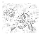
- FIG. 2 is an exploded perspective view of a locking member mounting structure of a seat belt retractor according to a first exemplary embodiment of the present invention
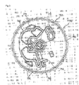
- FIG. 3 is a side view of the locking member mounting structure of the seat belt retractor according to the first exemplary embodiment of the present invention.
- the locking member mounting structure includes a leaf spring 755 fixed to a boss 751 of a locking clutch 750 and a fixing piece 761 which is formed to be projected from a lock arm 760 so as to be fixed to the leaf spring 755.
- a locking member 700 is installed in the seat belt retractor.
- the locking member 700 serves to smoothly rotate the webbing.
- the locking member 70 serves to restrict the webbing such that the webbing is not unfastened.
- the locking member 700 includes a locking base 710 fixed to one end of a guide drum (not shown) which is rotatably installed in a housing (not shown) forming a main body of the seat belt retractor, a locking clutch 750 which is rotatably coupled to one side surface of the locking base 710, and a lock arm 760 which is installed on one surface of the locking clutch 750 so as to rotate at a restricted angle.
- the locking clutch 750 is formed in a disc shape having a predetermined thickness. Further, the locking clutch 750 has latches 752 formed on the outer circumferential surface thereof, a through-hole 753 formed in the center thereof, and a boss 751 formed to project on one side surface thereof outside the through-hole 753. The locking base 710 is inserted into the through-hole 753.
- the leaf spring 755 with a predetermined length has one end fixed to the boss 75 and the other end extending toward a stopper 754 spaced from the boss 75.
- the other end of the leaf spring 755 is fixed to a fixing piece 761 of the lock arm 760.
- the stopper 754 which restricts the rotation of the lock arm 760 is formed in a predetermined position on the side surface of the locking clutch 750 where the boss 751 projects.
- the locking clutch 750 has a protrusion piece (not shown) formed on the other side surface thereof, the protrusion piece being inserted into a groove 711 formed in the locking base 710.
- the one end of the leaf spring 755 can be inserted and fixed to a groove or hole formed in the boss 751. Particularly, since the leaf spring 755 is wound along the outer circumferential surface of the boss 751, the one end of the leaf spring 755 can be fixed to the groove or hole formed in the boss 751.
- the fixing piece 761 projecting toward the leaf spring 755 is fixed to a predetermined position of the lock arm 760, that is, on the surface of the lock arm 760 coming in contact with the leaf spring 755.
- the fixing piece 761 has a penetrated hole or groove to which the leaf spring 755 is fixed.
- the locking base 710 is inserted and fixed to one side surface of the guide drum, and the locking clutch 750 is coupled to the one side surface of the locking base 710 so as to rotate at a predetermined angle.
- lock arm 760 is coupled to one side surface of the locking clutch 750 so as to rotate at a predetermined angle, and a mechanism cover (not shown) is fixed to the outside of the locking clutch 750.
- the one end of the leaf spring 755 coupled to the locking clutch 750 is inserted and fixed to a groove or hole formed in the boss 751, and the other end thereof is inserted and fixed to a groove or hole formed in the fixing piece 761.
- the webbing is rewound. Since the fastening or rewinding of the webbing is a basic operation of the seat belt retractor, the descriptions thereof will be brief.
- the guide drum is rotated so that the webbing is unfastened.
- the webbing is rewound by the restoring force of a spring built in a spring case (not shown) coupled to the seat belt retractor.
- the seat belt retractor restricts the webbing from being unfastened.
- the locking base 710 and the locking clutch 750 are rotated with the guide drum of the seat belt retractor. Further, the lock arm 760 installed in the locking clutch 750 is rotated in the restricted range.
- the lock arm 760 rotated in such a manner is locked to a latch of the mechanism cover, thereby preventing the webbing from being unfastened.
- the magnitudes of the rotational inertia forces generated in the lock arm 760 and the pawl of the locking base 710 differ depending on the pulling speed of the webbing and the rotational force. Therefore, the lock arm 760 and the pawl are separately driven depending on the magnitudes of the rotational inertia forces, thereby preventing the webbing from being unfastened.
- FIG. 4 is a side view of a locking member mounting structure of a seat belt retractor according to a second exemplary embodiment of the present invention.
- one end of a leaf spring 755a is fixed to the stopper 754 adjacent to the boss 751. That is, while one end of the leaf spring 755 is fixed to the boss 751 in the first exemplary embodiment, one end of the leaf spring 755a is fixed to the stopper 754, and the other end thereof is fixed to the fixing piece 761 of the lock arm 760 in the second exemplary embodiment.
- the shape of the leaf spring 755a differs from that of the first exemplary embodiment.
- the locking clutch 750 and the lock arm 760 are operated in the same manner as the first exemplary embodiment, and thus the descriptions thereof will be omitted.
- a third exemplary embodiment of the present invention will now be described with reference to FIG. 5 .
- the same reference numerals designate the same components as the first embodiment and description thereof will not be repeated.
- a torsion spring 755b of the present invention has one end coming in contact with one side of the lock arm 760.
- the torsion spring 755b extends in the rotation center direction of the lock arm 760 such that the middle portion of the torsion spring 755b is wound in a circular or circular-arc shape winding the rotation center axis of the lock arm 760.
- the other end of the torsion spring 755b is fixed to one side of the stopper 754.
- the torsion spring 755b extends to both sides with a symmetric angle from the rotation center of the lock arm 760.
- the one end of the torsion spring 755b comes in contact with the lock arm 760, and the other end thereof is fixed to the stopper 754.
- the one end of the torsion spring 755b fixed in such a manner serves as a free end such that the lock arm 760 can be rotated in the restricted angle range by a rotational inertia force, and the other end of the torsion spring 755b serves as a fixed end which is fixed to the stopper 754 so as not to move.
- the one end thereof freely moves using its elastic force in accordance with the rotation of the lock arm 760, and the other end thereof is fixed to the stopper 765 so as not to move. Therefore, the lock arm 760 is driven by the rotational inertia force, thereby preventing the webbing from being rapidly unfastened.
- the lock arm 760 is operated in the same manner as the first or second exemplary embodiment, and thus the specific descriptions thereof will be omitted.
- a fourth exemplary embodiment of the present invention will now be described with reference to FIG 6 , and the same reference numerals designate the same components as the above embodiments and description thereof will not be repeated.
- a leaf spring 755c of the fourth exemplary embodiment is formed in a straight line.
- One end of the leaf spring 755c is fixed to the lock arm 760, and the other end thereof passes through a slit 759a formed in the rotation center axis 759 of the lock arm 760 so as to be fixed to one side of a fixing protrusion 750 protruding from the locking clutch 750.
- the one end of the leaf spring 755c is fixed to the lock arm 760, and the other end of the leaf spring 755c passes through the rotation center axis 759 of the lock arm 760 so as to be fixed to one side of the fixing protrusion 758 protruding from the locking clutch 750.
- the one end thereof freely moves using its elastic force in accordance with the rotation of the lock arm 760, and the other end thereof is fixed to the fixing protrusion 758. Therefore, the lock arm 760 is driven by a rotational inertia force, thereby preventing the webbing from being rapidly unfastened.
- FIG. 7 is a perspective view of a leaf spring according to a fifth exemplary embodiment of the present invention.
- the leaf spring 755d has a curved portion 756 formed in the middle position thereof, the curved portion 756 being formed in a circular arc.
- Each of the leaf springs 755, 755a, 755b, and 755c of the above-described exemplary embodiments may have a curved portion in the middle position thereof, the curved portion being formed in a circular arc.
- the leaf spring 755b of the third exemplary embodiment may have a curved portion 756 in the middle position between the rotation center axis of the lock arm 760 and the leading end of the leaf spring 755b, in addition to the circular arc winding the rotation center axis of the lock arm 760.
- Such a curved portion 756 increases the elasticity of the leaf spring 755, 755a, 755b, or 755c. Further, although the leaf spring 755, 755a, 755b, or 755c is used for a long period, deformation of the leaf spring 755, 755a, 755b, or 755c is prevented, and elasticity is maintained.
- the locking clutch 750 and the lock arm 760 are operated in the same manner as the above-described exemplary embodiments, and thus descriptions thereof will be omitted.
- FIG. 8 is a perspective view of a leaf spring according to a sixth exemplary embodiment of the present invention.
- the leaf spring 755e of the sixth exemplary embodiment is formed in a stair shape composed of a plurality of stages.
- the locking clutch 750 and the lock arm 760 are operated in the same manner as the above-described exemplary embodiments, and thus descriptions thereof will be omitted.
- the spring which returns the lock arm installed in the locking clutch is simply assembled, which mean that assembly time of the spring is reduced to thereby increase productivity. Further, since the spring has a curved portion or is formed in a stair shape, the elasticity of the spring is maintained, and the deformation of the spring is prevented.
- the spring of the present invention is formed in various shapes. Therefore, although the shapes of the locking clutch and the lock arm are changed, the leaf spring can be applied thereto.
Landscapes
- Engineering & Computer Science (AREA)
- Mechanical Engineering (AREA)
- General Engineering & Computer Science (AREA)
- Automotive Seat Belt Assembly (AREA)
Abstract
Description
- This application claims the benefit of Korean Patent Application No.
2007-0047778, filed May 16, 2007 - The present invention relates to a locking member mounting structure of a seat belt retractor, and more specifically, to a locking member mounting structure of a seat belt retractor in which a lock arm is returned by a leaf spring extending from a protrusion.
- A seat belt or an airbag is installed in a vehicle to safely protect a driver and a passenger from traffic accidents.
- Such a seat belt is a basic safety device installed to operate upon vehicle accidents such as front collision, side collision, roll, and so on, to thereby maximally protect a driver and a passenger.
- A widely used seat belt is a three-point safety belt constituted of a waist belt for protecting the waist of the passenger (hereinafter, including "driver"), and a shoulder belt for protecting the shoulder and the breast. A guide pulley is coupled with the shoulder belt, a retractor is installed at a center pillar of a vehicle to release or wind the belt, and the waist belt is fastened to a locker panel.
- In addition, a tongue is inserted in a mid-portion of the belt, and the tongue can be locked to or released from a buckle fixed to a floor of the vehicle.
- Further, the retractor for winding or releasing the seat belt is classified into a non-locking retractor (NLR), an emergency locking retractor (ELR), and a web locking retractor (WLR).
- The non-locking retractor is locked after adjusting lengths of the shoulder belt and the waist belt. On the other hand, in the emergency locking retractor, the belt is freely retracted and rewound during stoppage or movement of the vehicle, and the belt is locked only when a vehicle collision causing abrupt deceleration occurs or when the belt is rapidly extracted.
- In addition, in the web locking retractor, a clamp directly grips the belt upon vehicle collision to stop extraction of the belt, thereby preventing serious injury to the passenger due to abrupt forward movement of the passenger.
- Meanwhile, Japanese Patent Laid-open Publication No.
H05-193441 - In the seat belt retractor, when a lock gear is relatively rotated in one direction with respect to a reel shaft, a projecting shaft is moved by a first cam, and a main pawl is rotated in one direction. Further, a gear to be engaged with first and second engagement pawls is determined, and the projecting shaft is moved along a hole. Therefore, a backup pawl is not rotated.
- In addition, when the lock gear is relatively rotated with respect to one direction, the first and second engagement pawls are geared with the gear, and the projecting pawl is moved along the diameter-direction hole. Then, the backup pawl is rotated in one direction, and a gear to be engaged with the backup pawl is determined. As the lock gear is relatively rotated with respect to one direction, the first and second engagement pawls are engaged with the gear. Simultaneously, the backup pawl is engaged with the gear.
- Further, Japanese Patent Laid-open Publication No.
2000-289571 - The webbing winding device includes a frame supported by a vehicle body, a winding shaft rotatably supported by the frame and winding a webbing for passenger-restriction in a layered manner, and a lock means for prohibiting rotation in a webbing extraction direction upon rapid deceleration of a vehicle.
- The lock means includes a first lock part concentrically disposed with respect to the winding shaft and rotated about the winding shaft to prevent rotation in a webbing extraction direction upon rapid deceleration of a vehicle, and a second lock part concentrically disposed with respect to the winding shaft, integrally rotated with the winding shaft, and plastically deformable to generate relative rotation with respect to the first lock part when the rotation of the first lock part in a webbing extraction direction is prevented.
- In addition, the webbing winding device further includes a third lock part formed of a single part, supported movable in radial direction by the second lock part, and having a high strength lock gear movable in radial outward direction when relative movement between the first lock part and the second lock part is generated, and a fourth lock part installed at the frame and having a high strength lock gear hooked with the lock gear of the third lock part when the third lock part moves in radial outward direction.
- Further, the webbing winding device further includes a guide part for displacing a predetermined portion of the second lock part in an opposite direction of an engagement position and plastically deforming the predetermined portion to be directly coupled to the fourth lock part using reaction when the lock gear of the third lock part is engaged with the lock gear of the fourth lock part.
- In addition, Japanese Patent Laid-open Publication No.
2000-302010 - The webbing winding device includes a winding shaft, which is engaged with an end of a webbing belt restricting the body of a passenger in a mounted state and winds the webbing belt by rotating in a winding direction around the shaft by itself, and a lock unit having a rotating body which can coaxially rotate in an extraction direction opposite to the winding direction with respect to the rotation of the winding shaft and a lock mechanism which is interlocked with the relative rotation of the rotating body in the winding direction with respect to the winding shaft so as to lock the rotation of the winding shaft in the extraction direction.
- Further, the webbing winding device includes a pair of walls, of which one wall is installed in the rotating body and the other wall is installed in the rotating body so as to face the one wall in the winding direction side of the one wall, and a compression coil spring which is disposed between the pair of walls. The compression coil is compressed by a pressing force from the other wall, caused by the rotation of the winding shaft, and simultaneously, presses the one wall using a restoring force from the compressed state.
- In addition, the webbing winding device includes a restriction unit which is integrally installed in the rotating body and the winding shaft, respectively. The restriction unit restricts the displacement of the compression coil spring along a direction crossing the axis of the compression coil spring outside the compression coil spring.
- Further, the webbing winding device includes an insertion hole which passes through the rotating body between the pair of walls and toward the other wall rather than the one wall. Further, an opening dimension from the one wall to the other wall is more than the overall length of the compressed compression coil spring and is less than the overall length of the compression coil spring in a normal state. The compression coil spring having the rotating body interposed therein can be inserted between the pair of walls and into the restriction unit from the opposite side to the walls through the insertion hole.
- Meanwhile, Japanese Patent Laid-open Publication No.
2003-212085 - The safety belt retractor includes a "⊏"-shaped housing body constituted of a pair of opposite side plates having through-holes, respectively, a shaft body integrally rotatably connected to the winding drum, on which the webbing is wound, passing through the through-holes to be rotatably supported by the side plates, and rotatably pused in a webbing winding direction, an emergency lock mechanism for stopping rotation of a webbing in an extraction direction of the shaft body, and first and second lock start mechanisms for operating the emergency lock mechanism.
- The emergency lock mechanism includes a lock gear formed at an inner periphery of one through-hole of the housing body, a lock base mounted inside the lock gear to be integrally rotated with the shaft body, and a pawl retained at the lock base and engaged with the lock gear projecting from an outer periphery of the lock base.
- In addition, the safety belt retractor includes a lock clutch rotatably mounted with respect to the shaft body adjacent to an outer surface of the lock base, synchronously rotatably mounted at the lock base in a state that pushed in the webbing extraction direction, having a ratchet wheel having a ratchet formed at its outer periphery, having an interlocking pin projected from the pawl and slidably guided by relative rotation with respect to the lock base, and having a guide groove projecting from the pawl.
- Further, the first lock start mechanism includes an inertia mass body rocked in response to abrupt acceleration of a vehicle, and a sensor lever engaged with the ratchet of the ratchet wheel depending on rocking of the inertia mass body to prevent rotation of the lock clutch body.
- Furthermore, the second lock start mechanism includes a cover body coupled to the housing body covering a portion of the first and second lock mechanisms, disposed inside the ratchet wheel, and having a cylindrical coupling inner periphery wall having inner periphery teeth projecting therefrom, and a lock arm rotatably supported at one side of the lock clutch body with respect to the cover body to prevent rotation of the lock clutch engaged with an internal gear by rotation delay in an opposite direction of the bias direction caused by abrupt rotation of the lock clutch body biased in an opposite direction separated from the internal gear of the coupling inner periphery wall.
- The cover body includes an inner periphery wall support part, which is formed projecting toward the side plates.
- As shown in
Fig. 1 , thelock clutch body 12 coupled to the safety belt retractor has aspring support 12c projecting on one side surface thereof and arelease spring 22 installed in another position of thelock clutch body 12. Thespring support 12c is loosely inserted so as to freely move inside a spring housing portion formed in thelock clutch body 12. - To return the lock arm, the seat belt retractor has a rocking stopper as well as the release spring installed therein. The rocking stopper restricts an angle at which the lock arm is rotated. Therefore, the shape and structure of the lock clutch are very complex. Further, since the release spring is coupled to the lock arm, it is difficult to assemble the release spring, and assembly time is lengthened, thereby increasing manufacturing cost.
- The present invention has been made to solve the above-described problems, and an object of the present invention is to provide a locking member mounting structure of a seat belt retractor which returns a lock arm by using the elasticity of a leaf spring, without a troublesome release spring installed therein.
- In order to accomplish the object, an aspect of the present invention provides a locking member mounting structure of a seat belt retractor including: a locking base coupled to one side of a guide drum; a locking clutch rotatably coupled to one side surface of the locking base; a lock arm coupled to one side surface of the locking clutch so as to rotate at a predetermined angle; a fixing piece projecting from one surface of the lock arm; and a spring for recovering the lock arm, wherein one end of the spring is fixed to a center boss of the locking clutch, and the other end is fixed to the fixing piece.
- Another aspect of the present invention provides a locking member mounting structure of a seat belt retractor including: a locking base coupled to one side of a guide drum; a locking clutch rotatably coupled to one side surface of the locking base; a lock arm coupled to one side surface of the locking clutch so as to rotate at a predetermined angle; a fixing piece projecting from one surface of the lock arm; and a spring for recovering the lock arm, wherein one end of the spring is fixed to a stopper formed at the locking clutch, and the other end is fixed to the fixing piece.
- Still another aspect of the present invention provides a locking member mounting structure of a seat belt retractor including: a locking base coupled to one side of a guide drum; a locking clutch rotatably coupled to one side surface of the locking base; a lock arm coupled to one side surface of the locking clutch so as to rotate at a predetermined angle; and a spring formed in an arcuate shape to be inserted into a boss forming a rotation center of the lock arm and extending toward both sides of the arcuate shape, wherein one end of the spring is fixed to the lock arm and the other end of the spring is fixed to a stopper formed at the locking clutch.
- Yet another aspect of the present invention provide a locking member mounting structure of a seat belt retractor including: a locking base coupled to one side of a guide drum; a locking clutch rotatably coupled to one side surface of the locking base; and a lock arm coupled to one side surface of the locking clutch so as to rotate at a predetermined angle, and further includes a slit straightly formed at a rotation center of the lock arm; and a spring inserted into the slit to be straightly fixed to one surface of the lock arm.
- In addition, the end of the spring fixed to the lock arm may form a free end which is rotated in accordance with the rotation of the lock arm.
- Further, the spring may have a curved portion formed in the middle position thereof.
- Furthermore, the spring may be formed in a stair shape composed of a plurality of stages.
- In addition, the spring may be a leaf spring.
- Further, the spring may be a torsion spring.
- The above and other objects, features and advantages of the present invention will be more apparent from the following detailed description taken in conjunction with the accompanying drawings, in which:
-
FIG. 1 is a side view of a conventional seat belt retractor; -
FIG. 2 is an exploded perspective view of a locking member mounting structure of a seat belt retractor according to a first embodiment of the present invention; -
FIG. 3 is a side view of the locking member mounting structure of the seat belt retractor according to the first embodiment; -
FIG. 4 is a side view of a locking member mounting structure of a seat belt retractor according to a second exemplary embodiment of the present invention; -
FIG. 5 is an exploded perspective view of a leaf spring according to a third exemplary embodiment of the present invention; -
FIG. 6 is an exploded perspective view of a leaf spring according to a fourth exemplary embodiment of the present invention; -
FIG. 7 is a perspective view of a leaf spring according to a fifth exemplary embodiment of the present invention; and -
FIG. 8 is a perspective view of a leaf spring according to a sixth exemplary embodiment of the present invention. - Hereinafter, exemplary embodiments of the present invention will be described with reference to the accompanying drawings.
-
FIG. 2 is an exploded perspective view of a locking member mounting structure of a seat belt retractor according to a first exemplary embodiment of the present invention, andFIG. 3 is a side view of the locking member mounting structure of the seat belt retractor according to the first exemplary embodiment of the present invention. - As shown in
FIGS. 2 and3 , the locking member mounting structure includes aleaf spring 755 fixed to aboss 751 of a lockingclutch 750 and afixing piece 761 which is formed to be projected from alock arm 760 so as to be fixed to theleaf spring 755. - In the present invention, a locking
member 700 is installed in the seat belt retractor. When webbing is unfastened or rewound, the lockingmember 700 serves to smoothly rotate the webbing. Further, when the webbing is rapidly unfastened, the locking member 70 serves to restrict the webbing such that the webbing is not unfastened. - The locking
member 700 includes alocking base 710 fixed to one end of a guide drum (not shown) which is rotatably installed in a housing (not shown) forming a main body of the seat belt retractor, a locking clutch 750 which is rotatably coupled to one side surface of thelocking base 710, and alock arm 760 which is installed on one surface of the locking clutch 750 so as to rotate at a restricted angle. - As shown in
FIGS. 2 and3 , the lockingclutch 750 is formed in a disc shape having a predetermined thickness. Further, the lockingclutch 750 haslatches 752 formed on the outer circumferential surface thereof, a through-hole 753 formed in the center thereof, and aboss 751 formed to project on one side surface thereof outside the through-hole 753. The lockingbase 710 is inserted into the through-hole 753. - The
leaf spring 755 with a predetermined length has one end fixed to the boss 75 and the other end extending toward astopper 754 spaced from the boss 75. The other end of theleaf spring 755 is fixed to afixing piece 761 of thelock arm 760. Thestopper 754 which restricts the rotation of thelock arm 760 is formed in a predetermined position on the side surface of the locking clutch 750 where theboss 751 projects. - Further, the locking
clutch 750 has a protrusion piece (not shown) formed on the other side surface thereof, the protrusion piece being inserted into agroove 711 formed in thelocking base 710. - The one end of the
leaf spring 755 can be inserted and fixed to a groove or hole formed in theboss 751. Particularly, since theleaf spring 755 is wound along the outer circumferential surface of theboss 751, the one end of theleaf spring 755 can be fixed to the groove or hole formed in theboss 751. - In addition, the fixing
piece 761 projecting toward theleaf spring 755 is fixed to a predetermined position of thelock arm 760, that is, on the surface of thelock arm 760 coming in contact with theleaf spring 755. The fixingpiece 761 has a penetrated hole or groove to which theleaf spring 755 is fixed. - In the locking member mounting structure of seat belt retractor constructed in such a manner, the locking
base 710 is inserted and fixed to one side surface of the guide drum, and the lockingclutch 750 is coupled to the one side surface of thelocking base 710 so as to rotate at a predetermined angle. - Further, the
lock arm 760 is coupled to one side surface of the locking clutch 750 so as to rotate at a predetermined angle, and a mechanism cover (not shown) is fixed to the outside of the lockingclutch 750. - The one end of the
leaf spring 755 coupled to the lockingclutch 750 is inserted and fixed to a groove or hole formed in theboss 751, and the other end thereof is inserted and fixed to a groove or hole formed in the fixingpiece 761. - Accordingly, in a state where a passenger pulls or extracts webbing, the webbing is rewound. Since the fastening or rewinding of the webbing is a basic operation of the seat belt retractor, the descriptions thereof will be brief.
- That is, when a passenger pulls the webbing with a proper force so as to wear the webbing, the guide drum is rotated so that the webbing is unfastened. When the pulled webbing is released, the webbing is rewound by the restoring force of a spring built in a spring case (not shown) coupled to the seat belt retractor.
- As such, if the guide drum is rapidly rotated when the webbing is unfastened, the seat belt retractor restricts the webbing from being unfastened.
- When the webbing is unfastened as described above, the locking
base 710 and the locking clutch 750 are rotated with the guide drum of the seat belt retractor. Further, thelock arm 760 installed in the lockingclutch 750 is rotated in the restricted range. - In other words, when the passenger pulls the webbing at a normal speed, not rapidly, such that the webbing is unfastened, the locking
base 710, the lockingclutch 750, and thelock arm 760, which serve as the lockingmember 700, are rotated with the guide drum. - When the locking
member 700 is rotated, and if the pulling speed of the webbing increases, a rotational inertia force (centrifugal force) is generated in the lockingmember 700. Then, thelock arm 760 installed in the lockingclutch 750 is rotated by the rotational inertia force. - The
lock arm 760 rotated in such a manner is locked to a latch of the mechanism cover, thereby preventing the webbing from being unfastened. - Meanwhile, if the pulling speed of the webbing is increased when the locking
member 700 is rotated, a rotational inertia force is generated. Then, a pawl (not shown) coupled to thelocking base 710 is separately driven by the rotational inertia force. - The magnitudes of the rotational inertia forces generated in the
lock arm 760 and the pawl of thelocking base 710 differ depending on the pulling speed of the webbing and the rotational force. Therefore, thelock arm 760 and the pawl are separately driven depending on the magnitudes of the rotational inertia forces, thereby preventing the webbing from being unfastened. -
FIG. 4 is a side view of a locking member mounting structure of a seat belt retractor according to a second exemplary embodiment of the present invention. - In the second exemplary embodiment, like reference numerals refer to like components of the first exemplary embodiment, and thus duplicate descriptions thereof will be omitted.
- Different from the first exemplary embodiment, one end of a
leaf spring 755a is fixed to thestopper 754 adjacent to theboss 751. That is, while one end of theleaf spring 755 is fixed to theboss 751 in the first exemplary embodiment, one end of theleaf spring 755a is fixed to thestopper 754, and the other end thereof is fixed to the fixingpiece 761 of thelock arm 760 in the second exemplary embodiment. - In the second exemplary embodiment, only the shape of the
leaf spring 755a differs from that of the first exemplary embodiment. The lockingclutch 750 and thelock arm 760 are operated in the same manner as the first exemplary embodiment, and thus the descriptions thereof will be omitted. - A third exemplary embodiment of the present invention will now be described with reference to
FIG. 5 . The same reference numerals designate the same components as the first embodiment and description thereof will not be repeated. - As shown in
FIG. 5 , atorsion spring 755b of the present invention has one end coming in contact with one side of thelock arm 760. Thetorsion spring 755b extends in the rotation center direction of thelock arm 760 such that the middle portion of thetorsion spring 755b is wound in a circular or circular-arc shape winding the rotation center axis of thelock arm 760. The other end of thetorsion spring 755b is fixed to one side of thestopper 754. - That is, the
torsion spring 755b extends to both sides with a symmetric angle from the rotation center of thelock arm 760. The one end of thetorsion spring 755b comes in contact with thelock arm 760, and the other end thereof is fixed to thestopper 754. - The one end of the
torsion spring 755b fixed in such a manner serves as a free end such that thelock arm 760 can be rotated in the restricted angle range by a rotational inertia force, and the other end of thetorsion spring 755b serves as a fixed end which is fixed to thestopper 754 so as not to move. - In the
torsion spring 755b constructed in such a manner, the one end thereof freely moves using its elastic force in accordance with the rotation of thelock arm 760, and the other end thereof is fixed to the stopper 765 so as not to move. Therefore, thelock arm 760 is driven by the rotational inertia force, thereby preventing the webbing from being rapidly unfastened. - The
lock arm 760 is operated in the same manner as the first or second exemplary embodiment, and thus the specific descriptions thereof will be omitted. - A fourth exemplary embodiment of the present invention will now be described with reference to
FIG 6 , and the same reference numerals designate the same components as the above embodiments and description thereof will not be repeated. - As shown in
FIG. 6 , aleaf spring 755c of the fourth exemplary embodiment is formed in a straight line. One end of theleaf spring 755c is fixed to thelock arm 760, and the other end thereof passes through aslit 759a formed in the rotation center axis 759 of thelock arm 760 so as to be fixed to one side of a fixingprotrusion 750 protruding from the lockingclutch 750. - That is, the one end of the
leaf spring 755c is fixed to thelock arm 760, and the other end of theleaf spring 755c passes through the rotation center axis 759 of thelock arm 760 so as to be fixed to one side of the fixingprotrusion 758 protruding from the lockingclutch 750. - In the
leaf spring 755c according to the fourth exemplary embodiment of the present invention, the one end thereof freely moves using its elastic force in accordance with the rotation of thelock arm 760, and the other end thereof is fixed to the fixingprotrusion 758. Therefore, thelock arm 760 is driven by a rotational inertia force, thereby preventing the webbing from being rapidly unfastened. -
FIG. 7 is a perspective view of a leaf spring according to a fifth exemplary embodiment of the present invention. - In the fifth embodiment, the
leaf spring 755d has acurved portion 756 formed in the middle position thereof, thecurved portion 756 being formed in a circular arc. - Each of the
leaf springs leaf spring 755b of the third exemplary embodiment may have acurved portion 756 in the middle position between the rotation center axis of thelock arm 760 and the leading end of theleaf spring 755b, in addition to the circular arc winding the rotation center axis of thelock arm 760. - Such a
curved portion 756 increases the elasticity of theleaf spring leaf spring leaf spring - In the fifth exemplary embodiment, the locking
clutch 750 and thelock arm 760 are operated in the same manner as the above-described exemplary embodiments, and thus descriptions thereof will be omitted. -
FIG. 8 is a perspective view of a leaf spring according to a sixth exemplary embodiment of the present invention. - The
leaf spring 755e of the sixth exemplary embodiment is formed in a stair shape composed of a plurality of stages. In the sixth exemplary embodiment, the lockingclutch 750 and thelock arm 760 are operated in the same manner as the above-described exemplary embodiments, and thus descriptions thereof will be omitted. - According to the present invention, the spring which returns the lock arm installed in the locking clutch is simply assembled, which mean that assembly time of the spring is reduced to thereby increase productivity. Further, since the spring has a curved portion or is formed in a stair shape, the elasticity of the spring is maintained, and the deformation of the spring is prevented.
- Further, the spring of the present invention is formed in various shapes. Therefore, although the shapes of the locking clutch and the lock arm are changed, the leaf spring can be applied thereto.
- While this invention has been described with reference to exemplary embodiments thereof, it will be clear to those of ordinary skill in the art to which the present invention pertains that various modifications may be made to the described embodiments without departing from the spirit and scope of the present invention as defined in the appended claims and their equivalents.
Claims (9)
Applications Claiming Priority (1)
| Application Number | Priority Date | Filing Date | Title |
|---|---|---|---|
| KR1020070047778A KR100835936B1 (en) | 2007-05-16 | 2007-05-16 | Locking member coupling structure of seat belt retractor |
Publications (3)
| Publication Number | Publication Date |
|---|---|
| EP1992531A2 true EP1992531A2 (en) | 2008-11-19 |
| EP1992531A3 EP1992531A3 (en) | 2012-11-14 |
| EP1992531B1 EP1992531B1 (en) | 2014-02-26 |
Family
ID=39671733
Family Applications (1)
| Application Number | Title | Priority Date | Filing Date |
|---|---|---|---|
| EP08156307.4A Active EP1992531B1 (en) | 2007-05-16 | 2008-05-15 | Locking member mounting structure of seat belt retractor |
Country Status (6)
| Country | Link |
|---|---|
| US (1) | US8608101B2 (en) |
| EP (1) | EP1992531B1 (en) |
| JP (1) | JP4189018B2 (en) |
| KR (1) | KR100835936B1 (en) |
| CN (1) | CN101306677B (en) |
| BR (1) | BRPI0703318A2 (en) |
Cited By (2)
| Publication number | Priority date | Publication date | Assignee | Title |
|---|---|---|---|---|
| WO2013060394A1 (en) * | 2011-10-26 | 2013-05-02 | Autoliv Development Ab | Safety belt device for winding and unwinding a safety belt |
| WO2017211624A1 (en) * | 2016-06-06 | 2017-12-14 | Trw Automotive Gmbh | Belt retractor for a vehicle safety belt |
Families Citing this family (12)
| Publication number | Priority date | Publication date | Assignee | Title |
|---|---|---|---|---|
| JP2011246011A (en) * | 2010-05-27 | 2011-12-08 | Tokai Rika Co Ltd | Webbing take-up device |
| KR102044500B1 (en) * | 2011-12-27 | 2019-11-13 | 아우토리브 디벨롭먼트 아베 | Self-locking belt retractor with switch-off action on its belt-strap-sensitive control system that is effective in the winding direction of the belt shaft |
| TWM436669U (en) | 2012-02-23 | 2012-09-01 | Woo Sing Ind Co Ltd | Ratchet brake structure |
| DE102012016118A1 (en) * | 2012-08-15 | 2014-02-20 | Trw Automotive Gmbh | locking mechanism |
| JP6250427B2 (en) * | 2013-02-12 | 2017-12-20 | 芦森工業株式会社 | Seat belt retractor |
| CN103832388B (en) * | 2014-02-27 | 2016-04-27 | 上海和励信息科技有限公司 | For driver element holding firmware and the prefastening safety device of prefastening safety device |
| JP6306537B2 (en) * | 2015-05-29 | 2018-04-04 | 株式会社東海理化電機製作所 | Webbing take-up device |
| CN104896037A (en) * | 2015-06-04 | 2015-09-09 | 湖南猎豹汽车股份有限公司 | Locking ring for bidirectionally transmitting torque, clutch and two-speed automatic transmission with locking ring |
| CN109591757B (en) * | 2018-11-26 | 2021-02-19 | 浙江顶昌汽车部件有限公司 | Automobile safety belt retractor with anti-locking device |
| US10946831B2 (en) * | 2019-02-25 | 2021-03-16 | Autoliv Asp, Inc. | Retractor pretensioner assembly |
| CN111216676B (en) * | 2020-03-06 | 2025-03-04 | 沈阳金杯锦恒汽车安全系统有限公司 | A friction plate clutch assembly and seat belt retractor |
| CN222629196U (en) * | 2024-04-10 | 2025-03-18 | 泰州润杰物流安全装备科技有限公司 | Intelligent safety control belt-retracting tensioning device |
Citations (4)
| Publication number | Priority date | Publication date | Assignee | Title |
|---|---|---|---|---|
| JPH05193441A (en) | 1991-04-11 | 1993-08-03 | Takata Kk | Seat belt retractor |
| JP2000289571A (en) | 1999-04-09 | 2000-10-17 | Tokai Rika Co Ltd | Webbing winding device |
| JP2000302010A (en) | 1999-04-16 | 2000-10-31 | Tokai Rika Co Ltd | Webbing takeup device |
| JP2003212085A (en) | 2002-01-25 | 2003-07-30 | Ashimori Ind Co Ltd | Retractor for seat belt |
Family Cites Families (30)
| Publication number | Priority date | Publication date | Assignee | Title |
|---|---|---|---|---|
| DE2733008A1 (en) * | 1977-07-21 | 1979-02-01 | Kolb Gmbh & Co Hans | SAFETY BELT ROLLER DEVICE |
| JPS54138232A (en) * | 1978-04-18 | 1979-10-26 | Takada Kogyo Kk | Emergency lock system belt takinggup motion |
| US4278216A (en) * | 1979-04-19 | 1981-07-14 | Juichiro Takada | Double-safety emergency locking belt retractor |
| SE449722B (en) * | 1980-06-02 | 1987-05-18 | Takata Kojyo Co | EMERGENCY WELDING ROLLER FOR VEHICLE SEAT BELTS |
| JPS5740456U (en) * | 1980-08-19 | 1982-03-04 | ||
| JPS6116152A (en) | 1984-07-03 | 1986-01-24 | N S K Warner Kk | emergency rock retractor |
| US4726540A (en) * | 1986-11-17 | 1988-02-23 | General Motors Corporation | Variable sensitivity seat belt retractor |
| US4801105A (en) * | 1987-10-01 | 1989-01-31 | Pzf, Inc. | Shoulder harness reel assembly with automatic reel lock |
| EP0382870B1 (en) * | 1989-02-17 | 1992-10-14 | Trw Repa Gmbh | Seat belt retractor |
| US5257754A (en) * | 1991-07-17 | 1993-11-02 | Trw Vehicle Safety Systems Inc. | Retractor |
| JP3093852B2 (en) * | 1992-01-30 | 2000-10-03 | タカタ株式会社 | Seat belt retractor |
| GB9215855D0 (en) * | 1992-07-25 | 1992-09-09 | Bsrd Ltd | Improvements to emergency locking passenger safety belt mechanisms |
| JP3322773B2 (en) * | 1994-07-06 | 2002-09-09 | エヌエスケー・オートリブ株式会社 | Seat belt retractor with pretensioner |
| WO1996003295A1 (en) * | 1994-07-21 | 1996-02-08 | Alliedsignal Inc. | Seat belt retractor and improved sensing mechanism |
| US5495994A (en) * | 1994-09-07 | 1996-03-05 | Trw Vehicle Safety Systems Inc. | Inertia sensitive seat belt retractor |
| JP3787001B2 (en) * | 1996-05-24 | 2006-06-21 | エヌエスケー・オートリブ株式会社 | Seat belt retractor |
| DE19758495C2 (en) * | 1997-08-12 | 2003-12-04 | Hs Tech & Design | seatbelt |
| US5984223A (en) * | 1998-06-05 | 1999-11-16 | Takata Corporation | Seat belt retractor and its spool |
| JP3980777B2 (en) * | 1998-11-02 | 2007-09-26 | 株式会社東海理化電機製作所 | Webbing take-up device |
| CN1128078C (en) * | 1999-02-16 | 2003-11-19 | 日商东海理化电机制作所股份有限公司 | Seat Belt Retractor |
| GB2349119B (en) * | 1999-04-21 | 2001-05-30 | Breed Automotive Tech | A sensor for a seat belt retractor |
| DE29917679U1 (en) * | 1999-10-07 | 2000-02-24 | TRW Occupant Restraint Systems GmbH & Co. KG, 73553 Alfdorf | Locking mechanism for a belt retractor |
| JP4785246B2 (en) * | 1999-12-15 | 2011-10-05 | タカタ株式会社 | Seat belt device |
| JP3984061B2 (en) | 2002-01-25 | 2007-09-26 | 芦森工業株式会社 | Seat belt retractor |
| US6698677B1 (en) * | 2002-11-12 | 2004-03-02 | H. Koch & Sons Co., Inc. | Restraint pretensioner |
| JP4295552B2 (en) * | 2003-05-16 | 2009-07-15 | 株式会社東海理化電機製作所 | Webbing take-up device |
| DE10324195B4 (en) * | 2003-05-28 | 2008-12-11 | Autoliv Development Ab | Seat belt retractor with a rotation angle defined shutdown of the web-sensitive control system |
| JP2005271623A (en) | 2004-03-23 | 2005-10-06 | Tokai Rika Co Ltd | Webbing winding device |
| US7934673B2 (en) * | 2004-04-01 | 2011-05-03 | Kabushiki Kaisha Tokai-Rika-Denki-Seisakusho | Webbing take-up device |
| US7401815B2 (en) * | 2005-03-17 | 2008-07-22 | Antoliv Asp, Inc. | Dual spool retractor seat belt system |
-
2007
- 2007-05-16 KR KR1020070047778A patent/KR100835936B1/en active Active
- 2007-07-25 CN CN2007101391036A patent/CN101306677B/en not_active Expired - Fee Related
- 2007-07-25 BR BRPI0703318-4A patent/BRPI0703318A2/en not_active IP Right Cessation
- 2007-07-25 JP JP2007192764A patent/JP4189018B2/en not_active Expired - Fee Related
-
2008
- 2008-05-14 US US12/152,664 patent/US8608101B2/en not_active Expired - Fee Related
- 2008-05-15 EP EP08156307.4A patent/EP1992531B1/en active Active
Patent Citations (4)
| Publication number | Priority date | Publication date | Assignee | Title |
|---|---|---|---|---|
| JPH05193441A (en) | 1991-04-11 | 1993-08-03 | Takata Kk | Seat belt retractor |
| JP2000289571A (en) | 1999-04-09 | 2000-10-17 | Tokai Rika Co Ltd | Webbing winding device |
| JP2000302010A (en) | 1999-04-16 | 2000-10-31 | Tokai Rika Co Ltd | Webbing takeup device |
| JP2003212085A (en) | 2002-01-25 | 2003-07-30 | Ashimori Ind Co Ltd | Retractor for seat belt |
Cited By (2)
| Publication number | Priority date | Publication date | Assignee | Title |
|---|---|---|---|---|
| WO2013060394A1 (en) * | 2011-10-26 | 2013-05-02 | Autoliv Development Ab | Safety belt device for winding and unwinding a safety belt |
| WO2017211624A1 (en) * | 2016-06-06 | 2017-12-14 | Trw Automotive Gmbh | Belt retractor for a vehicle safety belt |
Also Published As
| Publication number | Publication date |
|---|---|
| EP1992531B1 (en) | 2014-02-26 |
| KR100835936B1 (en) | 2008-06-09 |
| CN101306677A (en) | 2008-11-19 |
| EP1992531A3 (en) | 2012-11-14 |
| BRPI0703318A2 (en) | 2009-01-06 |
| JP4189018B2 (en) | 2008-12-03 |
| JP2008285137A (en) | 2008-11-27 |
| US8608101B2 (en) | 2013-12-17 |
| CN101306677B (en) | 2011-05-11 |
| US20090057469A1 (en) | 2009-03-05 |
Similar Documents
| Publication | Publication Date | Title |
|---|---|---|
| US8608101B2 (en) | Locking member mounting structure of seat belt retractor | |
| US20090057471A1 (en) | Seat belt retractor | |
| JP4976241B2 (en) | Seat belt retractor and seat belt device using the same | |
| CN110027502B (en) | Seatbelt retractor and seatbelt device for a motor vehicle | |
| US8684294B2 (en) | Seat belt retractor and seat belt apparatus including the same | |
| US6732969B2 (en) | Seatbelt retractor | |
| US20110140502A1 (en) | Seat belt retractor and seat belt apparatus including the same | |
| JP5511076B2 (en) | Seat belt retractor and seat belt device provided with the same | |
| US20090096201A1 (en) | Seat Belt Retractor and Seat Belt Apparatus | |
| US9573563B2 (en) | Webbing take-up device | |
| US8128016B2 (en) | Torsion bar support structure of seat belt retractor | |
| US9573562B2 (en) | Webbing take-up device | |
| WO2020052400A1 (en) | Seat belt retractor, and seat belt assembly | |
| JPH0572612U (en) | Webbing retractor | |
| JPH08133011A (en) | Webbing winding device | |
| US20100013292A1 (en) | Seat belt retractor | |
| EP1992530B1 (en) | Cover structure of seat belt retractor | |
| US4482102A (en) | Webbing-lock mechanism suitable for use in vehicle seat belt | |
| JPS6218520Y2 (en) | ||
| JPH0241091Y2 (en) | ||
| JPS606371Y2 (en) | safety belt retractor | |
| JPH0330210Y2 (en) | ||
| JPS594672Y2 (en) | webbing lock device | |
| JPH0834315A (en) | Seat-belt retractor | |
| JPH0572613U (en) | Webbing retractor |
Legal Events
| Date | Code | Title | Description |
|---|---|---|---|
| PUAI | Public reference made under article 153(3) epc to a published international application that has entered the european phase |
Free format text: ORIGINAL CODE: 0009012 |
|
| 17P | Request for examination filed |
Effective date: 20080616 |
|
| AK | Designated contracting states |
Kind code of ref document: A2 Designated state(s): AT BE BG CH CY CZ DE DK EE ES FI FR GB GR HR HU IE IS IT LI LT LU LV MC MT NL NO PL PT RO SE SI SK TR |
|
| AX | Request for extension of the european patent |
Extension state: AL BA MK RS |
|
| RAP1 | Party data changed (applicant data changed or rights of an application transferred) |
Owner name: DELPHI KOREA LIMITED LIABILITY COMPANY |
|
| RAP1 | Party data changed (applicant data changed or rights of an application transferred) |
Owner name: AUTOLIV DEVELOPMENT AB |
|
| PUAL | Search report despatched |
Free format text: ORIGINAL CODE: 0009013 |
|
| AK | Designated contracting states |
Kind code of ref document: A3 Designated state(s): AT BE BG CH CY CZ DE DK EE ES FI FR GB GR HR HU IE IS IT LI LT LU LV MC MT NL NO PL PT RO SE SI SK TR |
|
| AX | Request for extension of the european patent |
Extension state: AL BA MK RS |
|
| RIC1 | Information provided on ipc code assigned before grant |
Ipc: B60R 22/38 20060101AFI20121011BHEP Ipc: B60R 22/405 20060101ALI20121011BHEP |
|
| AKY | No designation fees paid | ||
| REG | Reference to a national code |
Ref country code: DE Ref legal event code: R108 |
|
| RBV | Designated contracting states (corrected) |
Designated state(s): DE FR |
|
| RIC1 | Information provided on ipc code assigned before grant |
Ipc: B60R 22/405 20060101ALI20130715BHEP Ipc: B60R 22/38 20060101AFI20130715BHEP |
|
| REG | Reference to a national code |
Ref country code: DE Ref legal event code: R108 Ref document number: 602008030405 Country of ref document: DE Effective date: 20130717 Ref country code: DE Ref legal event code: R108 Effective date: 20130717 |
|
| GRAP | Despatch of communication of intention to grant a patent |
Free format text: ORIGINAL CODE: EPIDOSNIGR1 |
|
| INTG | Intention to grant announced |
Effective date: 20130911 |
|
| GRAS | Grant fee paid |
Free format text: ORIGINAL CODE: EPIDOSNIGR3 |
|
| GRAA | (expected) grant |
Free format text: ORIGINAL CODE: 0009210 |
|
| RIN1 | Information on inventor provided before grant (corrected) |
Inventor name: LEE, JUNG-MIN 193-52, MYEONMOK 2-DONG, Inventor name: KIM, JONG-KAG 3-905, LOTTE APT., DANGYE-DONG, Inventor name: LEE, DONG-SUB Inventor name: CHOI, IN-SU 505, DOSIN 4-RI, Inventor name: BAE, GI-YOUNG, 104-104, E-PYEONHANSESANG Inventor name: KIM, DO-SIK 5/2, 296-47, SILLIM-DONG, Inventor name: LEE, BYUNG-JIN 101-1201, YOUNGNAM MANSION Inventor name: BAI, SANG-HONG 208, SUNGWOO HOUSE, DONGHWA-RI, |
|
| AK | Designated contracting states |
Kind code of ref document: B1 Designated state(s): DE FR |
|
| REG | Reference to a national code |
Ref country code: DE Ref legal event code: R096 Ref document number: 602008030405 Country of ref document: DE Effective date: 20140403 |
|
| REG | Reference to a national code |
Ref country code: DE Ref legal event code: R097 Ref document number: 602008030405 Country of ref document: DE |
|
| PLBE | No opposition filed within time limit |
Free format text: ORIGINAL CODE: 0009261 |
|
| STAA | Information on the status of an ep patent application or granted ep patent |
Free format text: STATUS: NO OPPOSITION FILED WITHIN TIME LIMIT |
|
| 26N | No opposition filed |
Effective date: 20141127 |
|
| REG | Reference to a national code |
Ref country code: DE Ref legal event code: R097 Ref document number: 602008030405 Country of ref document: DE Effective date: 20141127 |
|
| REG | Reference to a national code |
Ref country code: FR Ref legal event code: PLFP Year of fee payment: 9 |
|
| REG | Reference to a national code |
Ref country code: FR Ref legal event code: PLFP Year of fee payment: 10 |
|
| REG | Reference to a national code |
Ref country code: FR Ref legal event code: PLFP Year of fee payment: 11 |
|
| PGFP | Annual fee paid to national office [announced via postgrant information from national office to epo] |
Ref country code: DE Payment date: 20250528 Year of fee payment: 18 |
|
| PGFP | Annual fee paid to national office [announced via postgrant information from national office to epo] |
Ref country code: FR Payment date: 20250526 Year of fee payment: 18 |