EP1992397A1 - Method and device for safe storage and use of volatile ammonia storage materials - Google Patents
Method and device for safe storage and use of volatile ammonia storage materials Download PDFInfo
- Publication number
- EP1992397A1 EP1992397A1 EP07009810A EP07009810A EP1992397A1 EP 1992397 A1 EP1992397 A1 EP 1992397A1 EP 07009810 A EP07009810 A EP 07009810A EP 07009810 A EP07009810 A EP 07009810A EP 1992397 A1 EP1992397 A1 EP 1992397A1
- Authority
- EP
- European Patent Office
- Prior art keywords
- ammonia
- storage material
- pressure
- ammonia storage
- absorbing
- Prior art date
- Legal status (The legal status is an assumption and is not a legal conclusion. Google has not performed a legal analysis and makes no representation as to the accuracy of the status listed.)
- Granted
Links
Images


Classifications
-
- B—PERFORMING OPERATIONS; TRANSPORTING
- B01—PHYSICAL OR CHEMICAL PROCESSES OR APPARATUS IN GENERAL
- B01D—SEPARATION
- B01D53/00—Separation of gases or vapours; Recovering vapours of volatile solvents from gases; Chemical or biological purification of waste gases, e.g. engine exhaust gases, smoke, fumes, flue gases, aerosols
- B01D53/34—Chemical or biological purification of waste gases
- B01D53/92—Chemical or biological purification of waste gases of engine exhaust gases
- B01D53/94—Chemical or biological purification of waste gases of engine exhaust gases by catalytic processes
- B01D53/9404—Removing only nitrogen compounds
- B01D53/9409—Nitrogen oxides
- B01D53/9431—Processes characterised by a specific device
-
- B—PERFORMING OPERATIONS; TRANSPORTING
- B01—PHYSICAL OR CHEMICAL PROCESSES OR APPARATUS IN GENERAL
- B01D—SEPARATION
- B01D53/00—Separation of gases or vapours; Recovering vapours of volatile solvents from gases; Chemical or biological purification of waste gases, e.g. engine exhaust gases, smoke, fumes, flue gases, aerosols
- B01D53/34—Chemical or biological purification of waste gases
- B01D53/74—General processes for purification of waste gases; Apparatus or devices specially adapted therefor
- B01D53/86—Catalytic processes
- B01D53/90—Injecting reactants
-
- B—PERFORMING OPERATIONS; TRANSPORTING
- B01—PHYSICAL OR CHEMICAL PROCESSES OR APPARATUS IN GENERAL
- B01D—SEPARATION
- B01D53/00—Separation of gases or vapours; Recovering vapours of volatile solvents from gases; Chemical or biological purification of waste gases, e.g. engine exhaust gases, smoke, fumes, flue gases, aerosols
- B01D53/34—Chemical or biological purification of waste gases
- B01D53/92—Chemical or biological purification of waste gases of engine exhaust gases
- B01D53/94—Chemical or biological purification of waste gases of engine exhaust gases by catalytic processes
- B01D53/9404—Removing only nitrogen compounds
- B01D53/9409—Nitrogen oxides
-
- C—CHEMISTRY; METALLURGY
- C01—INORGANIC CHEMISTRY
- C01C—AMMONIA; CYANOGEN; COMPOUNDS THEREOF
- C01C1/00—Ammonia; Compounds thereof
- C01C1/003—Storage or handling of ammonia
- C01C1/006—Storage or handling of ammonia making use of solid ammonia storage materials, e.g. complex ammine salts
-
- F—MECHANICAL ENGINEERING; LIGHTING; HEATING; WEAPONS; BLASTING
- F01—MACHINES OR ENGINES IN GENERAL; ENGINE PLANTS IN GENERAL; STEAM ENGINES
- F01N—GAS-FLOW SILENCERS OR EXHAUST APPARATUS FOR MACHINES OR ENGINES IN GENERAL; GAS-FLOW SILENCERS OR EXHAUST APPARATUS FOR INTERNAL-COMBUSTION ENGINES
- F01N3/00—Exhaust or silencing apparatus having means for purifying, rendering innocuous, or otherwise treating exhaust
- F01N3/08—Exhaust or silencing apparatus having means for purifying, rendering innocuous, or otherwise treating exhaust for rendering innocuous
- F01N3/10—Exhaust or silencing apparatus having means for purifying, rendering innocuous, or otherwise treating exhaust for rendering innocuous by thermal or catalytic conversion of noxious components of exhaust
- F01N3/18—Exhaust or silencing apparatus having means for purifying, rendering innocuous, or otherwise treating exhaust for rendering innocuous by thermal or catalytic conversion of noxious components of exhaust characterised by methods of operation; Control
- F01N3/20—Exhaust or silencing apparatus having means for purifying, rendering innocuous, or otherwise treating exhaust for rendering innocuous by thermal or catalytic conversion of noxious components of exhaust characterised by methods of operation; Control specially adapted for catalytic conversion
- F01N3/206—Adding periodically or continuously substances to exhaust gases for promoting purification, e.g. catalytic material in liquid form, NOx reducing agents
- F01N3/2066—Selective catalytic reduction [SCR]
-
- F—MECHANICAL ENGINEERING; LIGHTING; HEATING; WEAPONS; BLASTING
- F01—MACHINES OR ENGINES IN GENERAL; ENGINE PLANTS IN GENERAL; STEAM ENGINES
- F01N—GAS-FLOW SILENCERS OR EXHAUST APPARATUS FOR MACHINES OR ENGINES IN GENERAL; GAS-FLOW SILENCERS OR EXHAUST APPARATUS FOR INTERNAL-COMBUSTION ENGINES
- F01N2610/00—Adding substances to exhaust gases
- F01N2610/02—Adding substances to exhaust gases the substance being ammonia or urea
-
- F—MECHANICAL ENGINEERING; LIGHTING; HEATING; WEAPONS; BLASTING
- F01—MACHINES OR ENGINES IN GENERAL; ENGINE PLANTS IN GENERAL; STEAM ENGINES
- F01N—GAS-FLOW SILENCERS OR EXHAUST APPARATUS FOR MACHINES OR ENGINES IN GENERAL; GAS-FLOW SILENCERS OR EXHAUST APPARATUS FOR INTERNAL-COMBUSTION ENGINES
- F01N2610/00—Adding substances to exhaust gases
- F01N2610/06—Adding substances to exhaust gases the substance being in the gaseous form
-
- F—MECHANICAL ENGINEERING; LIGHTING; HEATING; WEAPONS; BLASTING
- F01—MACHINES OR ENGINES IN GENERAL; ENGINE PLANTS IN GENERAL; STEAM ENGINES
- F01N—GAS-FLOW SILENCERS OR EXHAUST APPARATUS FOR MACHINES OR ENGINES IN GENERAL; GAS-FLOW SILENCERS OR EXHAUST APPARATUS FOR INTERNAL-COMBUSTION ENGINES
- F01N2610/00—Adding substances to exhaust gases
- F01N2610/10—Adding substances to exhaust gases the substance being heated, e.g. by heating tank or supply line of the added substance
-
- F—MECHANICAL ENGINEERING; LIGHTING; HEATING; WEAPONS; BLASTING
- F01—MACHINES OR ENGINES IN GENERAL; ENGINE PLANTS IN GENERAL; STEAM ENGINES
- F01N—GAS-FLOW SILENCERS OR EXHAUST APPARATUS FOR MACHINES OR ENGINES IN GENERAL; GAS-FLOW SILENCERS OR EXHAUST APPARATUS FOR INTERNAL-COMBUSTION ENGINES
- F01N2610/00—Adding substances to exhaust gases
- F01N2610/14—Arrangements for the supply of substances, e.g. conduits
- F01N2610/1406—Storage means for substances, e.g. tanks or reservoirs
-
- H—ELECTRICITY
- H01—ELECTRIC ELEMENTS
- H01M—PROCESSES OR MEANS, e.g. BATTERIES, FOR THE DIRECT CONVERSION OF CHEMICAL ENERGY INTO ELECTRICAL ENERGY
- H01M8/00—Fuel cells; Manufacture thereof
- H01M8/04—Auxiliary arrangements, e.g. for control of pressure or for circulation of fluids
- H01M8/04082—Arrangements for control of reactant parameters, e.g. pressure or concentration
- H01M8/04201—Reactant storage and supply, e.g. means for feeding, pipes
- H01M8/04216—Reactant storage and supply, e.g. means for feeding, pipes characterised by the choice for a specific material, e.g. carbon, hydride, absorbent
-
- H—ELECTRICITY
- H01—ELECTRIC ELEMENTS
- H01M—PROCESSES OR MEANS, e.g. BATTERIES, FOR THE DIRECT CONVERSION OF CHEMICAL ENERGY INTO ELECTRICAL ENERGY
- H01M8/00—Fuel cells; Manufacture thereof
- H01M8/22—Fuel cells in which the fuel is based on materials comprising carbon or oxygen or hydrogen and other elements; Fuel cells in which the fuel is based on materials comprising only elements other than carbon, oxygen or hydrogen
- H01M8/222—Fuel cells in which the fuel is based on compounds containing nitrogen, e.g. hydrazine, ammonia
-
- Y—GENERAL TAGGING OF NEW TECHNOLOGICAL DEVELOPMENTS; GENERAL TAGGING OF CROSS-SECTIONAL TECHNOLOGIES SPANNING OVER SEVERAL SECTIONS OF THE IPC; TECHNICAL SUBJECTS COVERED BY FORMER USPC CROSS-REFERENCE ART COLLECTIONS [XRACs] AND DIGESTS
- Y02—TECHNOLOGIES OR APPLICATIONS FOR MITIGATION OR ADAPTATION AGAINST CLIMATE CHANGE
- Y02A—TECHNOLOGIES FOR ADAPTATION TO CLIMATE CHANGE
- Y02A50/00—TECHNOLOGIES FOR ADAPTATION TO CLIMATE CHANGE in human health protection, e.g. against extreme weather
- Y02A50/20—Air quality improvement or preservation, e.g. vehicle emission control or emission reduction by using catalytic converters
-
- Y—GENERAL TAGGING OF NEW TECHNOLOGICAL DEVELOPMENTS; GENERAL TAGGING OF CROSS-SECTIONAL TECHNOLOGIES SPANNING OVER SEVERAL SECTIONS OF THE IPC; TECHNICAL SUBJECTS COVERED BY FORMER USPC CROSS-REFERENCE ART COLLECTIONS [XRACs] AND DIGESTS
- Y02—TECHNOLOGIES OR APPLICATIONS FOR MITIGATION OR ADAPTATION AGAINST CLIMATE CHANGE
- Y02E—REDUCTION OF GREENHOUSE GAS [GHG] EMISSIONS, RELATED TO ENERGY GENERATION, TRANSMISSION OR DISTRIBUTION
- Y02E60/00—Enabling technologies; Technologies with a potential or indirect contribution to GHG emissions mitigation
- Y02E60/30—Hydrogen technology
- Y02E60/50—Fuel cells
-
- Y—GENERAL TAGGING OF NEW TECHNOLOGICAL DEVELOPMENTS; GENERAL TAGGING OF CROSS-SECTIONAL TECHNOLOGIES SPANNING OVER SEVERAL SECTIONS OF THE IPC; TECHNICAL SUBJECTS COVERED BY FORMER USPC CROSS-REFERENCE ART COLLECTIONS [XRACs] AND DIGESTS
- Y02—TECHNOLOGIES OR APPLICATIONS FOR MITIGATION OR ADAPTATION AGAINST CLIMATE CHANGE
- Y02T—CLIMATE CHANGE MITIGATION TECHNOLOGIES RELATED TO TRANSPORTATION
- Y02T10/00—Road transport of goods or passengers
- Y02T10/10—Internal combustion engine [ICE] based vehicles
- Y02T10/12—Improving ICE efficiencies
Definitions
- This invention relates to ammonia storage and in particular to a method and apparatus for safe ammonia storage and release from a storage material capable of binding and releasing ammonia reversibly.
- Ammonia adsorbing and absorbing materials can be used as solid storage media for ammonia, which in turn, for example, may be used as the reductant in selective catalytic reduction (SCR) to reduce NO x emissions of automotive vehicles, see e.g. WO 99/01205 .
- SCR selective catalytic reduction
- ammonia is released from those materials by thermal desorption by means of external (see e.g. WO 99/01205 ) or internal (see e.g. WO 2006/012903 ) heating of the container containing them. In many applications this way of storing and delivering ammonia has certain advantages compared to liquid ammonia or aqueous solutions of ammonia or urea.
- Metal ammine salts which are ammonia reversibly absorbing and desorbing materials can be used as solid storage media for ammonia.
- WO 99/01205 uses preferably granulated Ca(NH 3 ) 8 Cl 2 or Sr(NH 3 ) 8 Cl 2 as an ammonia storage material.
- metal ammine salt forms with a high volumetric ammonia storage capacity are described.
- solid storage media usually ammonia is released from the solid storage media by thermal desorption. Also, solid storage media may be exposed to high temperatures by environmental conditions. Particularly in closed systems high ammonia vapor pressures may result.
- the invention in a first aspect relates to a method for storing and delivering ammonia wherein at least two ammonia storage materials capable of reversibly adsorbing or absorbing ammonia having different ammonia vapor pressures are used.
- Ammonia storage material having a lower vapor pressure which is only partially saturated with ammonia or void of ammonia, is brought into fluid communication with ammonia storage material having a higher ammonia vapor pressure to adsorb or absorb ammonia released from the ammonia storage material having a higher ammonia vapor pressure when the latter is higher than a pressure threshold.
- an apparatus for storing and delivering ammonia which comprises first and second storing/delivery units connectable in fluid communication and containing first and second ammonia storage materials capable of reversibly ad- or absorbing and desorbing ammonia, wherein the first ammonia storage material in the first storing/delivery unit has a higher vapor pressure than a second ammonia storage material in the second storing/delivery unit.
- a third aspect is an automotive NO x treatment system comprising such apparatus.
- the embodiments pertain to methods and apparatuses 100, 100', 100" using at least two storage materials 1 a, 2a capable of binding and releasing ammonia reversibly by ad- or absorption and desorption and having different ammonia pressures and capable to actively lower the ammonia vapor pressure in the apparatus 100, 100', 100 " or system by using the material 2a having the lower ammonia vapor pressure to absorb ammonia from the system when the pressure therein exceeds a threshold level by bringing the two materials 1 a, 2a into fluid communication when the pressure increases beyond a threshold level.
- the two materials 1 a, 2a may be accommodated in one container (not shown) divided e.g. by a gate or gate valve before they are brought into fluid communication, or they may be accommodated in to different containers 1, 2 connectable in fluid communication ( Fig. 1 , 2 , 3 ).
- the pressure threshold of the ammonia pressure varies with the constitution, configuration and operation requirements of the system.
- a different pressure threshold value for bringing the system in fluid communication with the second ammonia storage material from that in a stationary unit where strong walls can define the system may be desirable.
- the desired pressure threshold value may be considerably higher than in a relatively light thin walled mobile unit.
- the first ammonia storage material 1 a has a higher ammonia vapor pressure than the second ammonia storage material 2a. Both storage materials are ad- or absorbing and desorbing ammonia reversibly. Furthermore the second ammonia storage material 2a is only partly saturated with or void of ammonia when it is used to adsorb or absorb ammonia released from the first storage material 1 a after the predetermined pressure threshold value has been reached.
- ammonia storage materials 1 a, 2a adsorb or absorb ammonia reversibly.
- ammonia adsorbing materials are acid-treated active carbon materials and zeolites.
- ammonia absorbing materials are metal ammine complexes.
- a non-limiting example, which shows the usefulness of the embodiments of the invention, is as follows.
- a passive pressure build-up when e.g. a motor vehicle equipped with a container filled with an ammonia storage material is in a warm environment, e.g. parked in summer in the sun.
- a conventional ammonia storage and delivery system is heated to e.g. 60°C, with certain ammonia storage materials wherein the ammonia is relatively volatile the ammonia pressure may reach 3 bars or more. If the system has a leak at this pressure, ammonia will be released into the environment.
- an active heating of the container has been applied in order to create a suitable supply pressure, e.g.
- an ammonia storage and delivery system in an ammonia storage and delivery system according to embodiments of the invention in a motor vehicle it may be desirable to set the predetermined pressure threshold value at about ambient pressure or about 1 bar when the system is out of operation in order to avoid a possible leakage of ammonia into the environment.
- the pressure in the ammonia storage and delivery system of a motor vehicle may become undesirably high, e.g. when there is a failure of the heat control.
- first and second ammonia storage materials 1 a, 2a are contained in different containers 1, 2 or units that are connected e. g. by a pipe 20 which may comprise some type of valve 12 which is opened for bringing the two materials into fluid communication when the pressure threshold is exceeded.
- the first container 1 (main storage tank) is usually surrounded by an insulation layer 4b and has heating means 3a for the volatilization of ammonia from the storage material 1 a having the higher ammonia pressure.
- the second container 2 (storage chamber) is usually smaller than the main storage tank (1) and may optionally have heating means 3b. It may optionally be partly or fully surrounded by an insulation layer 4b, which may be a weakly insulating layer.
- the fluid communication can be interrupted and re-established, e.g. by a suitable valve 12.
- the fluid communication may e.g. be interrupted when a sufficiently low ammonia vapor pressure has been reached and re-established when the ammonia vapor pressure has again reached the threshold value.
- the first and second ammonia storage materials 1 a, 2a are at the same temperature. This may, e.g., be the case when a vehicle has been parked for a while and the first and second ammonia storage materials are exposed to the same temperature.
- the first ammonia storage material 1 a is at a higher temperature than said second ammonia storage material 2a. This may, e.g., be the case, when the first ammonia material is heated to release ammonia or when the operation of the system has just ended.
- the first ammonia material 1a is used as an ammonia source in a system having an ammonia consumption unit in operation.
- an ammonia consumption unit 200 or consumer may, without limitation, e.g. be a catalyst 8 for the selective catalytic reduction in oxygen-containing exhaust gas, as it is e.g. found in various combustion engines 7 fuelled by diesel, petrol or gasoline, natural gas, coal, hydrogen or other fossil or synthetic fuel or in other combustion processes.
- the reduction of NO x is effected in an automobile, truck, train, ship or other motorized machine, vehicle or power generator driven by a combustion engine 7.
- the ammonia consumption unit may be a catalytic device for splitting or cracking ammonia into nitrogen and hydrogen.
- the hydrogen produced may, e.g., be used in a power unit for generating electricity or as fuel etc.
- the ammonia consumption unit may also be a fuel cell which operates directly on ammonia.
- the ammonia source i.e. the first ammonia storage material 1 a
- the ammonia source may be heated to release the ammonia.
- the first ammonia storage material 1 a is brought into fluid communication with the second ammonia storage material 2a when the operation of the ammonia consumption unit 200 has ended and the pressure of the system is above the pressure threshold value.
- the first ammonia storage material 1 a may still be warm, if it has been heated for ammonia release even if the heating has been stopped. In this case the first ammonia storage material 1 a will continue to release ammonia, and since there is no more consumption a pressure build-up will be the result or at least an elevated pressure for an extended period of time will be maintained and the pressure threshold value may be reached.
- the second ammonia storage material 2a which is only partially saturated with or void of ammonia will then be brought into fluid communication with the first ammonia storage material 1 a and adsorb or absorb ammonia until the equilibrium ammonia pressure will be reached. As a result the pressure in the system 100, 100' will drop.
- the ammonia partial pressure at 25°C of the second ammonia storage material 2a is about or below 0.1 bar. In some embodiments the ammonia partial pressure of the first ammonia storage material 1 a is in the range of about 0.1 to 1.0 bar at 25°C. In some embodiments of the invention the first ammonia storage material 1 a has a higher ammonia partial pressure in its ammonia saturated state, e.g. 0.1 to 1.0 bar at 25°C, than the second ammonia storage material 2a in its saturated state at a given temperature which may e.g. have a pressure of below 0.1 bar at 25°C.
- first and second ammonia storage materials 1 a, 2a are identical materials when they are in the same ammonia saturated state. A difference in the ammonia vapor pressures is then achieved by the first ammonia storage material having a higher degree of saturation than the second ammonia storage material.
- At least one of the first and second ammonia storage materials 1 a, 2a reversibly absorbs and desorbs ammonia.
- the ammonia absorbing and desorbing material 1 a, 2a is a metal ammine complex.
- the metal ammine complex is selected from metal ammine complexes of the general formula: M a (NH 3 ) n X z , wherein M is one or more cations selected from alkali metals such as Li, Na, K or Cs, alkaline earth metals such as Mg, Ca or Sr, and/or transition metals such as V, Cr, Mn, Fe, Co, Ni, Cu, or Zn or combinations thereof such as NaAl, KAI, K 2 Zn, CsCu, or K 2 Fe, X is one or more anions selected from fluoride, chloride, bromide, iodide, nitrate, thiocyanate, sulphate, molybdate, and phosphate ions, a is the number of cations per salt molecule, z is the number of anions per salt molecule, and n is the coordination number of 2 to 12.
- M is one or more cations selected from alkali metals such as Li, Na, K or Cs, alka
- the first ammonia absorbing and desorbing material 1 a is Sr(NH 3 ) 8 Cl 2 or Ca(NH 3 ) 8 Cl 2 or a combination thereof.
- the second ammonia absorbing and desorbing material 2a is Mg(NH 3 ) 6 Cl 2 , Fe(NH 3 ) 6 Cl 2 or Ni(NH 3 ) 6 Cl 2 or a combination thereof.
- the ammonia vapor pressure of Mg(NH 3 ) 6 Cl 2 is much lower than that of both Sr(NH 3 ) 8 Cl 2 and Ca(NH 3 ) 8 Cl 2 at room temperature as well as at 60°C.
- Mg(NH 3 ) 6 Cl 2 and materials of similar low vapor pressure as an ammonia source for an ammonia consumption unit is very safe, since they do not develop high vapor pressures when e.g. exposed to strong sunlight; however they have to be heated to a temperature of above 100°C in order to reach an ammonia desorption pressure above 1 bar. This imposes restrictions on the material of the container, and furthermore the high operating temperature also consumes more power in order to operate the device on e.g. a car for ammonia delivery into the exhaust line for NO x reduction. A unit containing such an ammonia storage material would be operated on electrical heating and therefore an extra fuel consumption is involved when e.g.
- a power of say 100 W is provided by a generator that is driven by an engine having a thermal efficiency of 20-40%.
- any reduction in power consumption of an ammonia generating unit linked to the exhaust of an engine will have a significant influence on the overall fuel consumption of the car, truck or in another type of application.
- a more volatile storage material i.e. the storage material having a higher ammonia vapor pressure, such as Sr(NH 3 ) 8 Cl 2 or Ca(NH 3 ) 8 Cl 2 , would result in a lower power consumption when used as a source of ammonia for an ammonia consumption unit, however its use would not be as safe e.g. in view of the undesired passive pressure build-up in the temperature range from room temperature to 100°C.
- the present embodiments greatly increase the safety when using materials having relatively high ammonia vapor pressures.
- an ammonia storage material having a low ammonia vapour pressure i.e. binding ammonia much more strongly, such as Mg(NH 3 ) 6 Cl 2
- Mg(NH 3 ) 6 Cl 2 partially or totally ammonia-depleted state
- the ammonia source material as soon as there is a safety risk, such as failure of the heat control of the container with the ammonia source material or a higher pressure than desired after stopping the ammonia consumption unit, which would e.g. be the case, when a vehicle is parked or when the car safety system detects e.g. a crash-like incident or a fire. At least a part of the excess ammonia will then be absorbed by the MgCl 2 or similar material, thereby lowering the pressure in the system. Accordingly, a rapid reduction in operating pressure after ending the operation of the ammonia consumption unit can be achieved, as shown in Fig.
- the absorption of ammonia by a metal salt is exothermic, i.e. associated with the generation of heat of absorption.
- the second ammonia storage material 2a e.g. Mg(NH 3 ) 6 Cl 2 or its ammonia-depleted form MgCl 2 or a strongly adsorbing material such as acid-treated active carbon, therefore is in proximity to or contact with a material that can well dissipate heat to the surroundings, such as a metal and metal alloy. In this way, when the two storage units are in fluid communication the pressure of the system is governed by the temperature of the surroundings and the low ammonia pressure of the second storage material.
- a heating means 3b for heating the second ammonia storage material 2a e.g. by heating the second storage/deliver unit (storage chamber 2) when its saturation is higher than a threshold beyond which its absorption capacity is not sufficient to absorb ammonia to such an extend that the pressure in the system is reduced significantly.
- this can be effected during operation of the ammonia consumption unit 200, and the ammonia thus released from the second storage material 2a can be fed into the line 9 leading to the consumption unit 200, e.g. a catalyst 8 for reducing NO x .
- more than one main storage tank 1 containing ammonia storage and delivery material 1 a having a higher ammonia pressure and more than one, usually smaller storage chamber 2 containing ammonia storage and delivery material 2a having a lower ammonia vapour pressure and more than two different ammonia storage materials may be present in the apparatus 100, 100' for storing and delivering ammonia, if desired.
- the material in a first storage chamber 2 may be an ammonia reversibly ad- or absorbing and desorbing material and the material 13a in the second storage chamber (absorbing unit 13) may be an ammonia storage material that irreversibly and very strongly ad- or absorbs ammonia, such as active carbon treated with high amount so sulfuric acid.
- the second storage chamber (absorbing unit 13) may optionally be insulated 4c; this is, however, not the case, if it is an emergency unit in the case that the ammonia pressure in the system 100, 100', 100" for some reason exceeds an upper safety limit.
- the detection of an abnormal event such as a crash incident or a fire can result in rapid activation of the absorbing unit 13 and thus minimize the ammonia release in case of an accident. This is an additional safety feature of these embodiments.
- All the above storage units may be removably fastened to the apparatus or system 100, 100' in order to facilitate a possible exchange of the ammonia storage material.
- a buffer container 5 which is connected in fluid communication to at least one to the first storage/delivery unit (main storage tank 1) and the second storage unit (storage chamber 2).
- This buffer container 5 may serve for a better regulation of the pressure of the ammonia, which is delivered to the consumption unit (consumer) 200.
- Upstream and downstream of the buffer container 5 there may be control valves (only one (6) is shown) included in the lines to and from the same so as to control the ammonia flow into and out of the buffer container 5.
- Figure 1 shows an apparatus 100 for storing and delivering ammonia which includes a main storage tank 1 serving as a first storing/delivery unit and a storage chamber 2 serving as a second storing/delivery unit.
- the main storage tank 1 contains first ammonia storage material 1a having a vapour pressure (of absorbed ammonia) in the range of 0.1 to 1 bar at room temperature.
- the storage chamber 2 contains a second ammonia storage material 2a which binds ammonia stronger than the first storage material 1 a in the main storage tank 1 (at a lower vapour pressure in the range up to 0.1 bar).
- Main storage tank 1 is surrounded by an insulation layer/shell 4a and storage chamber 2 is surrounded by an insulation layer/shell 4b.
- These insulations/shells 4a, 4b may consist of suitable insulation materials such as mineral wool, rockwool, PUR, PIR or other insulation/shell materials suitable for the specific environmental conditions (temperature, humidity, chemical exposure) for the respective application.
- Such an insulation layer/shell may be filled with a porous material that is evacuated in order to further reduce the heat conductivity.
- the insulation layers/shells 4a, 4b may be protected by an insulation cover (not shown) or may be formed by a suitable shell material.
- Main storage tank 1 and storage tank 2 comprise heating means 3a and 3b.
- These heating means 3a, 3b may be either formed as internal heating means embedded into the first and second storage materials 1 a, 2a (see figure). They may also be arranged on the outside of the shell of the main storage tank 1 and the storage chamber 2 but on the inside of the insulation layer 4a and 4b.
- Suitable heating means 3a, 3b may be electrical resistance heating means or fluid heating means (hot water, steam, oil, exhaust gas, etc.), wherein the heating output is controlled by the control unit 11, either directly by controlling the electrical input (power supply) or indirectly by control valves (not shown) of the heating fluid lines (fluid supply and/or temperature).
- Ammonia is supplied through a tube 20 to an ammonia consumer (not shown).
- the supply is controlled by the dosing valve 6, wherein the supply pressure in the apparatus 100 can be detected by a pressure sensor 10 and the control unit 11 which controls the heater 3a accordingly.
- the dosing valve 6 may be of any suitable type electrically, pneumatically, or hydraulically operable and controllable.
- valve 12 to the storage chamber 2 is opened and the second storage material 2a in the storage chamber 2 absorbs ammonia from the main storage tank 1 and the first storage material 1 a respectively due to the difference in volatility. This process keeps the pressure in the main storage 1 tank close to or below 1 bar. Valve 12 is also controlled by the controlling unit 11.
- valve 6 and opening of valve 12 may also be effected by a link to the safety monitoring system of the vehicle. If e.g. a car is in a crash , the airbags will release immediately governed by an acceleration detector and this - as well as any other emergency signal from the safety monitoring system, e.g. the detection of a fire - may also trigger the closing of valve 6 and opening of valve 12.
- the usual safe storage temperature of the main unit is for example room temperature. If the system is placed at e.g. 60 C° a slow passive heating of both the main storage tank 1 and the storage chamber 2 will occur.
- the increase in temperature of the main storage tank 1 also causes a rise of the ammonia pressure within the first storage material 1 a. This pressure increase is detected by the pressure sensor 10; when the pressure is too high, e.g. above 1 bar, the valve 12 to the storage chamber 2 is opened and ammonia migrates from the main storage tank 1 to the storage chamber 2.
- the absorption of ammonia in the storage chamber 2 causes a temperature rise and the generated heat is dispersed through the insulation/shell 4b and the surface of the storage chamber 2 to the environment.
- the main storage tank 1 has an outside surface A 1 and the outside shell including the insulation 4a is characterised by a heat transfer factor ⁇ 1 and the storage chamber 2 has an outside surface A 2 and is also characterised by heat transfer number ⁇ 2 .
- the process can be kept up as long as the second storage material 2a is not completely saturated and is further illustrated by the example below.
- the heating means 3b of the storage chamber 2 is utilised if the second storage material 2a in the storage chamber 2 is saturated. By heating, the ammonia in the storage chamber 2 can be released through the valve 12 and the valve 6 to an ammonia absorption process.
- the storage chamber 2 can be used during the normal ammonia release to supplement the larger unit 1 or during a fast start-up.
- a check valve (not shown) may be provided in the line 20 between the valve 12 and the main storage tank 1. Such a check valve is only necessary, if the ammonia pressure in the second storage material 2a may rise higher than the ammonia pressure in the first storage material 1 a.
- Figure 2 shows an arrangement in which the apparatus according to Figure 1 is connected to an ammonia consumer system 200, specifically to the exhaust line 9 of a combustion engine 7.
- the system further comprises a buffer volume 5 between the main storage tank 1 and the dosing valve 6.
- This buffer volume 5 may increase the ability to dose high but short peak flows and also increases the controllability of the system.
- the released ammonia is led from the exhaust line 9 into a catalyst 8 where selective catalytic reduction of NO x with ammonia as the reductant is carried out.
- the system according to Fig. 2 shows the implementation of the invention for on-board ammonia storage and delivery for automotive NO x after treatment.
- FIG 3 shows an arrangement in which the apparatus according to Figure 2 further comprises an absorbing unit 13 having an insulation layer/shell 4c.
- This absorbing unit 13 is connected to the tube 20 leading form the main storage tank 1 to the buffer container 5 via a control valve 14.
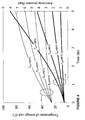
- Figure 4 shows the temperature (thin-line curves) and pressure (thick-line curves) development of an ammonia storage unit according to the prior art which is thermally insulated (corresponding to approximately 7 cm rockwool) without a second ammonia storage material wherein 5 kg of the only ammonia storage material (Ca(NH 3 ) 8 Cl 2 ) in the unit is initially at a temperature of 25°C and then exposed to external temperatures of 40, 60, 80 and 100°C (Text). Particularly in the cases of 60, 80 and 100°C the storage unit shows a significant increase in temperature (thin-line curves); after 5 hours the temperatures are in the interval of 45 to 80°C. The associated pressure is shown in the thick-line curves.
- Figure 5 shows the pressure (thin-line curve) development of an ammonia storage apparatus 100, 100' according to Figures 1 and 2 upon exposure to 60°C (external temperature; Text) wherein the first storage/delivery unit (main storage tank 1) containing 5 kg of Ca(NH 3 ) 8 Cl 2 which is thermally insulated (corresponding to approximately 7 cm rockwool) is in fluid communication with a smaller second' storage/delivery unit (storage chamber 2; not insulated) holding 500 g of MgCl 2 .
- the thick-line curve in Figure 5 is identical to the pressure curve at 60°C in Figure 4 , i.e. corresponds to the same prior art without a second ammonia storage material. In this case the pressure reaches more than 2 bars after 5 hours.
- Figure 6 is similar to Figure 5 , except that the apparatus 100, 100' is exposed to an external temperature of 80°C.
- the unit according to the prior art without a second ammonia storage material reaches a pressure of almost 4.5 bars after 5 hours, whereas the pressure in the system with an apparatus 100, 100' according to Figures 1 and 2 (thin-line curve) stays below 0.26 bar.
- Figure 7 shows the temperature (solid and dashed thick-line curves) and pressure (solid and dashed thin-line curves) development of a unit of the prior art (dashed curves; ammonia storage material: Ca(NH 3 ) 8 Cl 2 ) and of Figures 1 and 2 (solid curves; first ammonia storage material 1a: Ca(NH 3 ) 8 Cl 2 ; second ammonia storage material 2a: MgCl 2 ) that both have an initial temperature of 55°C and an initial ammonia pressure of 2.5 bars (a pressure which may be suitable for introducing ammonia into an exhaust line 9 of a motor vehicle slightly upstream of an NO x reducing catalyst 8) after having been in operation for 1 hour.
- the latter is the result of the endothermic ammonia desorption from the thermally insulated main tank containing 5 kg of Ca(NH 3 ) 8 Cl 2 which is driven by the exothermic absorption of ammonia into the 500 g of MgCl 2 contained in the smaller second storage/delivery unit (storage chamber 2) which is less or not insulated and can dissipate the heat of absorption.
- the data in Figure 7 correspond to an environmental temperature of 25°C. If the temperature were 40°C, the pressure in a system of the prior art without a second ammonia storage material would at least be 1.5 bars after 5 hours. In the systems of Figures 1 and 2 the pressure still would have been reduced to below 1 bar within a period of 1 hour.
- an ammonia storage and delivery system will remain at a level between the ammonia pressure of the first storage/delivery unit (main storage tank 1) containing material 1a having the higher ammonia pressure and the second, usually smaller storage/delivery unit (storage chamber 2) containing material 2a having the lower ammonia pressure when the main tank 1 and the storage chamber 2 are in fluid communication.
- the present method and system may be used in all mobile or portable systems comprising a catalyst for the selectively catalytic reduction of NO x , in fuel cells or in systems comprising a catalyst for splitting ammonia into nitrogen and hydrogen or in combination with other ammonia-consuming processes where the safe use of volatile ammonia ad- or absorbing and desorbing materials is required.
- a first storage/delivery unit or main storage tank 1 contains 10 kg of Sr(NH 3 ) 8 Cl 2 .
- a smaller second storage/delivery unit or storage chamber 2 initially contains 500 g MgCl 2 .
- the main storage tank 1, an 8-liter tank, has an external area A 1 of approximately 0.3 m 2 .
- ammonia desorption rate is found as 12 W divided by the molar ammonia desorption enthalpy (the enthalpy is approximately 42 kJ/mole NH 3 for Sr(NH 3 ) 8 Cl 2 ). That gives an ammonia release rate of roughly 2.9 * 10 -4 mol/sec or 4.9 * 10 -3 g NH 3 /sec.
- the system exemplified here can continuously be parked in an environment of 85°C for 30.3 hours without the pressure being raised significantly.
- the case presented here can be considered as the heat transfer needed both for raising the average temperature of the 8-liter unit as well as providing energy for ammonia release. There will be a lag-phase, where the 12 W of heating will only result in an elevation of the average temperature of the 8-liter unit whereas the ammonia release will use a greater fraction of the 12 W when the average temperature has raised e.g. from 25 to 45°C.
- the 12 W of heat transfer rate may be reduced over time as the external surface of the tank may increase in temperature and thus reduce the gradient between the surroundings and the surface of the storage tank.
Landscapes
- Chemical & Material Sciences (AREA)
- Engineering & Computer Science (AREA)
- Chemical Kinetics & Catalysis (AREA)
- Environmental & Geological Engineering (AREA)
- Health & Medical Sciences (AREA)
- Oil, Petroleum & Natural Gas (AREA)
- Analytical Chemistry (AREA)
- General Chemical & Material Sciences (AREA)
- Biomedical Technology (AREA)
- Combustion & Propulsion (AREA)
- Organic Chemistry (AREA)
- Inorganic Chemistry (AREA)
- Toxicology (AREA)
- Mechanical Engineering (AREA)
- General Engineering & Computer Science (AREA)
- Filling Or Discharging Of Gas Storage Vessels (AREA)
- Treating Waste Gases (AREA)
Abstract
Description
- This invention relates to ammonia storage and in particular to a method and apparatus for safe ammonia storage and release from a storage material capable of binding and releasing ammonia reversibly.
- Ammonia adsorbing and absorbing materials can be used as solid storage media for ammonia, which in turn, for example, may be used as the reductant in selective catalytic reduction (SCR) to reduce NOx emissions of automotive vehicles, see e.g.
WO 99/01205 WO 99/01205 WO 2006/012903 ) heating of the container containing them. In many applications this way of storing and delivering ammonia has certain advantages compared to liquid ammonia or aqueous solutions of ammonia or urea. - Metal ammine salts, which are ammonia reversibly absorbing and desorbing materials can be used as solid storage media for ammonia.
WO 99/01205 WO 2006/081824 metal ammine salt forms with a high volumetric ammonia storage capacity are described. - Usually ammonia is released from the solid storage media by thermal desorption. Also, solid storage media may be exposed to high temperatures by environmental conditions. Particularly in closed systems high ammonia vapor pressures may result.
- In a first aspect the invention relates to a method for storing and delivering ammonia wherein at least two ammonia storage materials capable of reversibly adsorbing or absorbing ammonia having different ammonia vapor pressures are used. Ammonia storage material having a lower vapor pressure, which is only partially saturated with ammonia or void of ammonia, is brought into fluid communication with ammonia storage material having a higher ammonia vapor pressure to adsorb or absorb ammonia released from the ammonia storage material having a higher ammonia vapor pressure when the latter is higher than a pressure threshold.
- According to another aspect of the invention an apparatus for storing and delivering ammonia is provided which comprises first and second storing/delivery units connectable in fluid communication and containing first and second ammonia storage materials capable of reversibly ad- or absorbing and desorbing ammonia, wherein the first ammonia storage material in the first storing/delivery unit has a higher vapor pressure than a second ammonia storage material in the second storing/delivery unit.
- A third aspect is an automotive NOx treatment system comprising such apparatus.
- Other features are inherent in the methods and products disclosed or will be apparent to the person skilled in the art from the following detailed description of embodiments and its accompanying drawings.
- Embodiments of the invention will now be described by way of example and with reference to the drawings, in which:
-
Fig. 1 shows an embodiment of an ammonia storage and delivery apparatus comprising a first storage/delivery unit (main storage tank) containing an ammonia storage material having a higher ammonia vapor pressure and a second storage delivery unit (storage chamber) smaller than the main storage tank and containing an ammonia storage material having a lower ammonia vapor pressure and which is only partially saturated with or void of ammonia in fluid communication. -
Fig. 2 shows another embodiment of an ammonia storage and delivery apparatus similar to the one ofFig. 1 and further comprising a buffer volume between the main tank and a dosing valve in an ammonia supply line leading into an exhaust line between an engine and a catalyst for selective reduction of NOx with ammonia. -
Fig. 3 shows another embodiment of an ammonia storage and delivery apparatus similar to the one ofFig. 2 and further comprising an absorbing unit containing an ammonia very strongly ad- or absorbing material. -
Fig. 4 shows the temperature (thin lines) and pressure (thick lines) development of an ammonia storage/delivery system according to the prior art without a second ammonia storage material wherein the ammonia storage material is initially at a temperature of 25 °C and then exposed to temperatures of 40, 60, 80 and 100°C. -
Fig. 5 shows the pressure development of an ammonia storage/delivery system according toFig. 1 or2 (thin line) wherein a first ammonia storage material having a higher ammonia vapor pressure and a second ammonia storage material having a lower ammonia vapor pressure, which is MgCl2 void of or only partially saturated with ammonia, are used in combination. The system is initially at a temperature of 25°C and is then exposed to a temperature of 60°C. A system according to the prior art is shown for comparison (thick line). -
Fig. 6 shows the pressure development of the systems ofFig. 5 when exposed to a temperature of 80°C. -
Fig. 7 shows the temperature development of a system of the prior art without a second storage material (thin dashed curved line) and of the system ofFig. 1 or2 (thin solid line) and the pressure development of a system of the prior art without the second storage material (thick dashed line) and of the system ofFig. 1 or2 (thick solid line) when cooling down from 55°C and a pressure of 2,5 bar in an ambient temperature of 25°C. - The embodiments pertain to methods and
apparatuses storage materials apparatus material 2a having the lower ammonia vapor pressure to absorb ammonia from the system when the pressure therein exceeds a threshold level by bringing the twomaterials - The two
materials different containers Fig. 1 ,2 ,3 ). - The pressure threshold of the ammonia pressure varies with the constitution, configuration and operation requirements of the system. In an ammonia storage and delivery system/
apparatus - The first
ammonia storage material 1 a has a higher ammonia vapor pressure than the secondammonia storage material 2a. Both storage materials are ad- or absorbing and desorbing ammonia reversibly. Furthermore the secondammonia storage material 2a is only partly saturated with or void of ammonia when it is used to adsorb or absorb ammonia released from thefirst storage material 1 a after the predetermined pressure threshold value has been reached. - The
ammonia storage materials - A non-limiting example, which shows the usefulness of the embodiments of the invention, is as follows. There will be a passive pressure build-up when e.g. a motor vehicle equipped with a container filled with an ammonia storage material is in a warm environment, e.g. parked in summer in the sun. When a conventional ammonia storage and delivery system is heated to e.g. 60°C, with certain ammonia storage materials wherein the ammonia is relatively volatile the ammonia pressure may reach 3 bars or more. If the system has a leak at this pressure, ammonia will be released into the environment. Also, when the ammonia storage and delivery system has been in operation, usually an active heating of the container has been applied in order to create a suitable supply pressure, e.g. 2-2,5 bar (absolute). When the vehicle is going to be parked the temperature of storage material will initially still be at the operation temperature and can release a limited quantity of ammonia even when the heating is terminated . Therefore, in a conventional system an elevated ammonia pressure will exist until the system has cooled down to room temperature (about 25°C). If the ambient temperature is higher than room temperature, e.g. 40°C, the pressure will remain elevated. Any leak in the system will discharge ammonia into the environment which is particularly undesirable when the vehicle is parked in a garage. Therefore, in an ammonia storage and delivery system according to embodiments of the invention in a motor vehicle it may be desirable to set the predetermined pressure threshold value at about ambient pressure or about 1 bar when the system is out of operation in order to avoid a possible leakage of ammonia into the environment.
- Also, when in operation the pressure in the ammonia storage and delivery system of a motor vehicle may become undesirably high, e.g. when there is a failure of the heat control. In this case, i.e. during operation of the vehicle, it may be desirable to set the predetermined pressure threshold at somewhat above the expected highest ammonia operation pressure (i.e. during the greatest possible ammonia demand of the NOx reducing catalyst), e.g. at about 5 bars, in order to avoid a possible leakage or even damage to the system.
- In some embodiments the first and second
ammonia storage materials different containers pipe 20 which may comprise some type ofvalve 12 which is opened for bringing the two materials into fluid communication when the pressure threshold is exceeded. - The first container 1 (main storage tank) is usually surrounded by an
insulation layer 4b and has heating means 3a for the volatilization of ammonia from thestorage material 1 a having the higher ammonia pressure. The second container 2 (storage chamber) is usually smaller than the main storage tank (1) and may optionally have heating means 3b. It may optionally be partly or fully surrounded by aninsulation layer 4b, which may be a weakly insulating layer. - In some embodiments the fluid communication can be interrupted and re-established, e.g. by a
suitable valve 12. The fluid communication may e.g. be interrupted when a sufficiently low ammonia vapor pressure has been reached and re-established when the ammonia vapor pressure has again reached the threshold value. - In some embodiments the first and second
ammonia storage materials - In other embodiments the first
ammonia storage material 1 a is at a higher temperature than said secondammonia storage material 2a. This may, e.g., be the case, when the first ammonia material is heated to release ammonia or when the operation of the system has just ended. - In some embodiments the
first ammonia material 1a is used as an ammonia source in a system having an ammonia consumption unit in operation. Such anammonia consumption unit 200 or consumer may, without limitation, e.g. be acatalyst 8 for the selective catalytic reduction in oxygen-containing exhaust gas, as it is e.g. found invarious combustion engines 7 fuelled by diesel, petrol or gasoline, natural gas, coal, hydrogen or other fossil or synthetic fuel or in other combustion processes. In some embodiments the reduction of NOx is effected in an automobile, truck, train, ship or other motorized machine, vehicle or power generator driven by acombustion engine 7. - In other embodiments the ammonia consumption unit may be a catalytic device for splitting or cracking ammonia into nitrogen and hydrogen. The hydrogen produced may, e.g., be used in a power unit for generating electricity or as fuel etc. The ammonia consumption unit may also be a fuel cell which operates directly on ammonia.
- When the ammonia released is consumed by a
consumption unit 200 the ammonia source, i.e. the firstammonia storage material 1 a, may be heated to release the ammonia. - In some embodiments the first
ammonia storage material 1 a is brought into fluid communication with the secondammonia storage material 2a when the operation of theammonia consumption unit 200 has ended and the pressure of the system is above the pressure threshold value. When the operation of theconsumption unit 200 has ended the firstammonia storage material 1 a may still be warm, if it has been heated for ammonia release even if the heating has been stopped. In this case the firstammonia storage material 1 a will continue to release ammonia, and since there is no more consumption a pressure build-up will be the result or at least an elevated pressure for an extended period of time will be maintained and the pressure threshold value may be reached. The secondammonia storage material 2a which is only partially saturated with or void of ammonia will then be brought into fluid communication with the firstammonia storage material 1 a and adsorb or absorb ammonia until the equilibrium ammonia pressure will be reached. As a result the pressure in thesystem 100, 100' will drop. - In some embodiments the ammonia partial pressure at 25°C of the second
ammonia storage material 2a is about or below 0.1 bar. In some embodiments the ammonia partial pressure of the firstammonia storage material 1 a is in the range of about 0.1 to 1.0 bar at 25°C. In some embodiments of the invention the firstammonia storage material 1 a has a higher ammonia partial pressure in its ammonia saturated state, e.g. 0.1 to 1.0 bar at 25°C, than the secondammonia storage material 2a in its saturated state at a given temperature which may e.g. have a pressure of below 0.1 bar at 25°C. In other embodiments the first and secondammonia storage materials - In some embodiments at least one of the first and second
ammonia storage materials desorbing material - In some embodiments the metal ammine complex is selected from metal ammine complexes of the general formula: Ma(NH3)nXz, wherein M is one or more cations selected from alkali metals such as Li, Na, K or Cs, alkaline earth metals such as Mg, Ca or Sr, and/or transition metals such as V, Cr, Mn, Fe, Co, Ni, Cu, or Zn or combinations thereof such as NaAl, KAI, K2Zn, CsCu, or K2Fe, X is one or more anions selected from fluoride, chloride, bromide, iodide, nitrate, thiocyanate, sulphate, molybdate, and phosphate ions, a is the number of cations per salt molecule, z is the number of anions per salt molecule, and n is the coordination number of 2 to 12.
- In some embodiments the first ammonia absorbing and
desorbing material 1 a is Sr(NH3)8Cl2 or Ca(NH3)8Cl2 or a combination thereof. In some embodiments the second ammonia absorbing anddesorbing material 2a is Mg(NH3)6Cl2, Fe(NH3)6Cl2 or Ni(NH3)6Cl2 or a combination thereof. - The vapor pressures of ammonia-saturated Mg(NH3)6Cl2, Sr(NH3)8Cl2 and Ca(NH3)8Cl2 are given in the table below.
Ammonia pressure (bar) at 25° C 60°C Mg(NH3)6Cl2 0.004 0.02 Sr(NH3)8Cl2 0.52 3.2 Ca(NH3)8Cl2 0.69 3.9 - The ammonia vapor pressure of Mg(NH3)6Cl2 is much lower than that of both Sr(NH3)8Cl2 and Ca(NH3)8Cl2 at room temperature as well as at 60°C.
- The use of Mg(NH3)6Cl2 and materials of similar low vapor pressure as an ammonia source for an ammonia consumption unit is very safe, since they do not develop high vapor pressures when e.g. exposed to strong sunlight; however they have to be heated to a temperature of above 100°C in order to reach an ammonia desorption pressure above 1 bar. This imposes restrictions on the material of the container, and furthermore the high operating temperature also consumes more power in order to operate the device on e.g. a car for ammonia delivery into the exhaust line for NOx reduction. A unit containing such an ammonia storage material would be operated on electrical heating and therefore an extra fuel consumption is involved when e.g. a power of say 100 W is provided by a generator that is driven by an engine having a thermal efficiency of 20-40%. As a result, any reduction in power consumption of an ammonia generating unit linked to the exhaust of an engine will have a significant influence on the overall fuel consumption of the car, truck or in another type of application.
- A more volatile storage material, i.e. the storage material having a higher ammonia vapor pressure, such as Sr(NH3)8Cl2 or Ca(NH3)8Cl2, would result in a lower power consumption when used as a source of ammonia for an ammonia consumption unit, however its use would not be as safe e.g. in view of the undesired passive pressure build-up in the temperature range from room temperature to 100°C. The present embodiments greatly increase the safety when using materials having relatively high ammonia vapor pressures.
- Accordingly, during normal operation of an ammonia consumption unit, the above metal ammine complexes having higher vapour pressures would be used as an ammonia source. A smaller amount of an ammonia storage material having a low ammonia vapour pressure, i.e. binding ammonia much more strongly, such as Mg(NH3)6Cl2, would in its partially or totally ammonia-depleted state (such as MgCl2) be brought into fluid contact with the metal ammine complex having the higher ammonia vapor pressure, i.e. the ammonia source material, as soon as there is a safety risk, such as failure of the heat control of the container with the ammonia source material or a higher pressure than desired after stopping the ammonia consumption unit, which would e.g. be the case, when a vehicle is parked or when the car safety system detects e.g. a crash-like incident or a fire. At least a part of the excess ammonia will then be absorbed by the MgCl2 or similar material, thereby lowering the pressure in the system. Accordingly, a rapid reduction in operating pressure after ending the operation of the ammonia consumption unit can be achieved, as shown in
Fig. 7 , and an excessive pressure build-up by passive heating when the ammonia consumption unit is exposed to a warm environment, e.g. when a car is parked in the sun, can be avoided as shown inFigs. 5 and6 . It is clear that by embodiments of the present invention a high degree of safety an be achieved. - The absorption of ammonia by a metal salt is exothermic, i.e. associated with the generation of heat of absorption. In some embodiments, the second
ammonia storage material 2a, e.g. Mg(NH3)6Cl2 or its ammonia-depleted form MgCl2 or a strongly adsorbing material such as acid-treated active carbon, therefore is in proximity to or contact with a material that can well dissipate heat to the surroundings, such as a metal and metal alloy. In this way, when the two storage units are in fluid communication the pressure of the system is governed by the temperature of the surroundings and the low ammonia pressure of the second storage material. - In some embodiments there is provided a heating means 3b for heating the second
ammonia storage material 2a, e.g. by heating the second storage/deliver unit (storage chamber 2) when its saturation is higher than a threshold beyond which its absorption capacity is not sufficient to absorb ammonia to such an extend that the pressure in the system is reduced significantly. In some embodiments this can be effected during operation of theammonia consumption unit 200, and the ammonia thus released from thesecond storage material 2a can be fed into theline 9 leading to theconsumption unit 200, e.g. acatalyst 8 for reducing NOx. Thereby it is possible to continuously keep the secondammonia storage material 2a more or less unsaturated and ready for absorbing ammonia when there is a need. - In some embodiments (not shown) more than one
main storage tank 1 containing ammonia storage anddelivery material 1 a having a higher ammonia pressure and more than one, usuallysmaller storage chamber 2 containing ammonia storage anddelivery material 2a having a lower ammonia vapour pressure and more than two different ammonia storage materials may be present in theapparatus 100, 100' for storing and delivering ammonia, if desired. - For example, the material in a
first storage chamber 2 may be an ammonia reversibly ad- or absorbing and desorbing material and thematerial 13a in the second storage chamber (absorbing unit 13) may be an ammonia storage material that irreversibly and very strongly ad- or absorbs ammonia, such as active carbon treated with high amount so sulfuric acid. The second storage chamber (absorbing unit 13) may optionally be insulated 4c; this is, however, not the case, if it is an emergency unit in the case that the ammonia pressure in thesystem first storage chamber 2, can result in rapid activation of the absorbingunit 13 and thus minimize the ammonia release in case of an accident. This is an additional safety feature of these embodiments. - All the above storage units (one or more
main storage tanks 1,storage chamber 2 and absorbing unit 13) may be removably fastened to the apparatus orsystem 100, 100' in order to facilitate a possible exchange of the ammonia storage material. - In some embodiments there may be a
buffer container 5, which is connected in fluid communication to at least one to the first storage/delivery unit (main storage tank 1) and the second storage unit (storage chamber 2). Thisbuffer container 5 may serve for a better regulation of the pressure of the ammonia, which is delivered to the consumption unit (consumer) 200. Upstream and downstream of thebuffer container 5 there may be control valves (only one (6) is shown) included in the lines to and from the same so as to control the ammonia flow into and out of thebuffer container 5. -
Figure 1 shows anapparatus 100 for storing and delivering ammonia which includes amain storage tank 1 serving as a first storing/delivery unit and astorage chamber 2 serving as a second storing/delivery unit. Themain storage tank 1 contains firstammonia storage material 1a having a vapour pressure (of absorbed ammonia) in the range of 0.1 to 1 bar at room temperature. Thestorage chamber 2 contains a secondammonia storage material 2a which binds ammonia stronger than thefirst storage material 1 a in the main storage tank 1 (at a lower vapour pressure in the range up to 0.1 bar). -
Main storage tank 1 is surrounded by an insulation layer/shell 4a andstorage chamber 2 is surrounded by an insulation layer/shell 4b. These insulations/shells shells -
Main storage tank 1 andstorage tank 2 comprise heating means 3a and 3b. These heating means 3a, 3b may be either formed as internal heating means embedded into the first andsecond storage materials main storage tank 1 and thestorage chamber 2 but on the inside of theinsulation layer control unit 11, either directly by controlling the electrical input (power supply) or indirectly by control valves (not shown) of the heating fluid lines (fluid supply and/or temperature). - Ammonia is supplied through a
tube 20 to an ammonia consumer (not shown). The supply is controlled by thedosing valve 6, wherein the supply pressure in theapparatus 100 can be detected by apressure sensor 10 and thecontrol unit 11 which controls theheater 3a accordingly. Thedosing valve 6 may be of any suitable type electrically, pneumatically, or hydraulically operable and controllable. - When the ammonia supply during a given ammonia demanding process has been stopped by closing the
dosing valve 6,valve 12 to thestorage chamber 2 is opened and thesecond storage material 2a in thestorage chamber 2 absorbs ammonia from themain storage tank 1 and thefirst storage material 1 a respectively due to the difference in volatility. This process keeps the pressure in themain storage 1 tank close to or below 1 bar.Valve 12 is also controlled by the controllingunit 11. - The closing of
valve 6 and opening ofvalve 12 may also be effected by a link to the safety monitoring system of the vehicle. If e.g. a car is in a crash , the airbags will release immediately governed by an acceleration detector and this - as well as any other emergency signal from the safety monitoring system, e.g. the detection of a fire - may also trigger the closing ofvalve 6 and opening ofvalve 12. - Another system application is possible in consideration of a warm environment. The usual safe storage temperature of the main unit is for example room temperature. If the system is placed at e.g. 60 C° a slow passive heating of both the
main storage tank 1 and thestorage chamber 2 will occur. The increase in temperature of themain storage tank 1 also causes a rise of the ammonia pressure within thefirst storage material 1 a. This pressure increase is detected by thepressure sensor 10; when the pressure is too high, e.g. above 1 bar, thevalve 12 to thestorage chamber 2 is opened and ammonia migrates from themain storage tank 1 to thestorage chamber 2. The absorption of ammonia in thestorage chamber 2 causes a temperature rise and the generated heat is dispersed through the insulation/shell 4b and the surface of thestorage chamber 2 to the environment. - This process can be continued as long as the heat transfer into the
main storage tank 1 is below the maximum heat transfer out of thestorage chamber 2. In other words, the uptake of heat (energy) in themain storage tank 1 resulting in ammonia desorption must be able to be released through the insulation/shell 4b of thestorage chamber 2 by heat dissipation through the insulation/shell layer 4b of thestorage chamber 2. - The
main storage tank 1 has an outside surface A1 and the outside shell including theinsulation 4a is characterised by a heat transfer factor α1 and thestorage chamber 2 has an outside surface A2 and is also characterised by heat transfer number α2. To allow for the above-mentioned process the following relation should hold:
- The process can be kept up as long as the
second storage material 2a is not completely saturated and is further illustrated by the example below. - The heating means 3b of the
storage chamber 2 is utilised if thesecond storage material 2a in thestorage chamber 2 is saturated. By heating, the ammonia in thestorage chamber 2 can be released through thevalve 12 and thevalve 6 to an ammonia absorption process. Thestorage chamber 2 can be used during the normal ammonia release to supplement thelarger unit 1 or during a fast start-up. - Thereby, it can be assured that there will always be a high capacity of ammonia absorption in the
storage chamber 2 since some of the absorbed ammonia is occasionally released into a connected ammonia consuming process. - To avoid a backflow in the
main storage tank 1 during release of ammonia from thestorage chamber 2, a check valve (not shown) may be provided in theline 20 between thevalve 12 and themain storage tank 1. Such a check valve is only necessary, if the ammonia pressure in thesecond storage material 2a may rise higher than the ammonia pressure in thefirst storage material 1 a. -
Figure 2 shows an arrangement in which the apparatus according toFigure 1 is connected to anammonia consumer system 200, specifically to theexhaust line 9 of acombustion engine 7. The system further comprises abuffer volume 5 between themain storage tank 1 and thedosing valve 6. Thisbuffer volume 5 may increase the ability to dose high but short peak flows and also increases the controllability of the system. The released ammonia is led from theexhaust line 9 into acatalyst 8 where selective catalytic reduction of NOx with ammonia as the reductant is carried out. The system according toFig. 2 shows the implementation of the invention for on-board ammonia storage and delivery for automotive NOx after treatment. -
Figure 3 shows an arrangement in which the apparatus according toFigure 2 further comprises an absorbingunit 13 having an insulation layer/shell 4c. This absorbingunit 13 is connected to thetube 20 leading form themain storage tank 1 to thebuffer container 5 via acontrol valve 14. - The two main aspects of the inventive apparatus relate to
- a) an
apparatus - b) a system or apparatus that circumvents the problem with pressure built-up in the main storage tank caused by passive heating in warm environments.
- In both cases the important feature is to avoid that in a car with an on-board ammonia reduction system an elevated ammonia pressure has (or will) build/t up during parking.
-
Figure 4 shows the temperature (thin-line curves) and pressure (thick-line curves) development of an ammonia storage unit according to the prior art which is thermally insulated (corresponding to approximately 7 cm rockwool) without a second ammonia storage material wherein 5 kg of the only ammonia storage material (Ca(NH3)8Cl2) in the unit is initially at a temperature of 25°C and then exposed to external temperatures of 40, 60, 80 and 100°C (Text). Particularly in the cases of 60, 80 and 100°C the storage unit shows a significant increase in temperature (thin-line curves); after 5 hours the temperatures are in the interval of 45 to 80°C. The associated pressure is shown in the thick-line curves. Only the unit exposed to 40°C does not build up a pressure above 1 bar in the course of 5 hours. The storage unit that is exposed to 80°C reaches a pressure of almost 4.5 bars after 5 hours, and the unit exposed to 100°C reaches a pressure a as high as that of fluid ammonia at room temperature, i.e. above 8 bars. Without insulation the increase in pressure and temperature would be even more dramatic. -
Figure 5 shows the pressure (thin-line curve) development of anammonia storage apparatus 100, 100' according toFigures 1 and2 upon exposure to 60°C (external temperature; Text) wherein the first storage/delivery unit (main storage tank 1) containing 5 kg of Ca(NH3)8Cl2 which is thermally insulated (corresponding to approximately 7 cm rockwool) is in fluid communication with a smaller second' storage/delivery unit (storage chamber 2; not insulated) holding 500 g of MgCl2. The thick-line curve inFigure 5 is identical to the pressure curve at 60°C inFigure 4 , i.e. corresponds to the same prior art without a second ammonia storage material. In this case the pressure reaches more than 2 bars after 5 hours. In the system according toFigures 1 and2 (thin-line curve) the ammonia pressure is lowered by the continuous absorption of ammonia by MgCl2. The temperature of the latter rises slowly by the heat of absorption. Eventually a steady state is reached where the system pressure reaches 0.1 bar, 1/10 of atmospheric pressure. -
Figure 6 is similar toFigure 5 , except that theapparatus 100, 100' is exposed to an external temperature of 80°C. The unit according to the prior art without a second ammonia storage material (thick-line curve) reaches a pressure of almost 4.5 bars after 5 hours, whereas the pressure in the system with anapparatus 100, 100' according toFigures 1 and2 (thin-line curve) stays below 0.26 bar. -
Figure 7 shows the temperature (solid and dashed thick-line curves) and pressure (solid and dashed thin-line curves) development of a unit of the prior art (dashed curves; ammonia storage material: Ca(NH3)8Cl2) and ofFigures 1 and2 (solid curves; firstammonia storage material 1a: Ca(NH3)8Cl2; secondammonia storage material 2a: MgCl2) that both have an initial temperature of 55°C and an initial ammonia pressure of 2.5 bars (a pressure which may be suitable for introducing ammonia into anexhaust line 9 of a motor vehicle slightly upstream of an NOx reducing catalyst 8) after having been in operation for 1 hour. The operation is then terminated, and the system is left in its natural environment. In the unit of the prior art, the temperature (dashed thick-line curve) and pressure (dashed thin-line curve) drop very slowly. It takes more than 3.5 hours until the system has reached a pressure below 1 bar. In the system ofFigures 1 and2 the pressure (solid thin-line curve) decreases to below 1 bar within a little more than half an hour due to the rapid temperature drop of the first storage/delivery unit (main storage tank 1) and thus of the whole system (solid thick-line curve). The latter is the result of the endothermic ammonia desorption from the thermally insulated main tank containing 5 kg of Ca(NH3)8Cl2 which is driven by the exothermic absorption of ammonia into the 500 g of MgCl2 contained in the smaller second storage/delivery unit (storage chamber 2) which is less or not insulated and can dissipate the heat of absorption. The data inFigure 7 correspond to an environmental temperature of 25°C. If the temperature were 40°C, the pressure in a system of the prior art without a second ammonia storage material would at least be 1.5 bars after 5 hours. In the systems ofFigures 1 and2 the pressure still would have been reduced to below 1 bar within a period of 1 hour. - With the present embodiments the pressure inside an ammonia storage and delivery system will remain at a level between the ammonia pressure of the first storage/delivery unit (main storage tank 1) containing
material 1a having the higher ammonia pressure and the second, usually smaller storage/delivery unit (storage chamber 2) containingmaterial 2a having the lower ammonia pressure when themain tank 1 and thestorage chamber 2 are in fluid communication. This greatly contributes to the safety of an ammonia storage and delivery system, which uses a solid ammonia ad- or absorbing and desorbing material having a relatively high ammonia pressure as an ammonia source. - The present method and system may be used in all mobile or portable systems comprising a catalyst for the selectively catalytic reduction of NOx, in fuel cells or in systems comprising a catalyst for splitting ammonia into nitrogen and hydrogen or in combination with other ammonia-consuming processes where the safe use of volatile ammonia ad- or absorbing and desorbing materials is required.
- A first storage/delivery unit or
main storage tank 1 contains 10 kg of Sr(NH3)8Cl2. A smaller second storage/delivery unit orstorage chamber 2 initially contains 500 g MgCl2. - A normal passenger car with a modern engine requires about 0.2-0.4g NOx to be removed per kilometer driven. It is assumed that a mass of 0.3 g NOx corresponds to 0.3 g/km*17/30=0.17g NH3/km consumed for reduction of NOx. Given those specifications, the system defined as above gives:

- The MgCl2 in the
smaller storage chamber 2 can absorb 0.517 * 500 g/(1-0.517)= 535 g NH3 (the mass fraction of ammonia in the fully saturated Mg(NH3)6Cl2 is 0.517). Given a density of approximately 1.2 g/cm3, the volume of the main 10 kg unit is approximately 8 liters. Themain storage tank 1, an 8-liter tank, has an external area A1 of approximately 0.3 m2. The heat transfer coefficient α1 of the insulated tank is assumed to be 0.2 W/K/m2, and when the temperature difference between container and surroundings is 85-25 Celsius = 60 Celsius (or K) the warming of the main storage tank is thus:
- Assuming all heat transfer results in ammonia desorption, the corresponding ammonia desorption rate is found as 12 W divided by the molar ammonia desorption enthalpy (the enthalpy is approximately 42 kJ/mole NH3 for Sr(NH3)8Cl2). That gives an ammonia release rate of roughly 2.9 * 10-4 mol/sec or 4.9 * 10-3 g NH3/sec.
- Since the MgCl2 unit 2 has a capacity of absorbing 535 g NH3, the system exemplified here can continuously be parked in an environment of 85°C for 30.3 hours without the pressure being raised significantly.
- The case presented here can be considered as the heat transfer needed both for raising the average temperature of the 8-liter unit as well as providing energy for ammonia release. There will be a lag-phase, where the 12 W of heating will only result in an elevation of the average temperature of the 8-liter unit whereas the ammonia release will use a greater fraction of the 12 W when the average temperature has raised e.g. from 25 to 45°C.
- In addition, the 12 W of heat transfer rate may be reduced over time as the external surface of the tank may increase in temperature and thus reduce the gradient between the surroundings and the surface of the storage tank.
Claims (36)
- A method for storing and delivering ammonia, wherein a first ammonia storage material capable of reversibly ad- or absorbing and desorbing ammonia has a higher ammonia vapor pressure than a second ammonia storage material capable of reversibly ad- or absorbing and desorbing ammonia and said second ammonia storage material having a lower ammonia vapor pressure than said first ammonia storage material and which is only partially saturated with or completely void of ammonia is brought into fluid communication with said first ammonia storage material when an ammonia vapor pressure of said first ammonia storage material is at or higher than a pressure threshold for ad- or absorbing ammonia released from said first ammonia storage material.
- The method of claim 1, wherein said first and second ammonia storage materials are contained in different containers in fluid communication.
- The method of claim 2 wherein said fluid communication can be interrupted and re-established.
- The method of any of claims 1 to 3, wherein the first and second ammonia storage materials are at the same temperature.
- The method of any of claims 1 to 3, wherein the first ammonia storage material is at a higher temperature than said second ammonia storage material.
- The method of any of claims 2 to 5, wherein said first ammonia storage material is used as an ammonia source in a system having an ammonia consumption unit in operation.
- The method of claim 6, wherein the ammonia consumption unit is a catalyst for selective catalytic reduction (SCR) of NOx in oxygen-containing exhaust gas.
- The method of claim 7 wherein SCR of NOx in the oxygen-containing exhaust gas is effected in an automobile, truck, train, ship or other motorized machine, vehicle or engine-driven generator.
- The method of claim 6, wherein the ammonia consumption unit is a catalytic device for splitting ammonia into nitrogen and hydrogen or a fuel cell.
- The method of any of claims 6 to 9, wherein said first ammonia storage material is brought into fluid contact with said second ammonia storage material at or above the pressure threshold when the operation of the ammonia consumption unit has ended in order to reduce the ammonia pressure in the system.
- The method of claim 10, wherein the pressure threshold is about ambient pressure.
- The method of any of claims 7, 8, 10 and 11, wherein said first ammonia storage material is brought into fluid contact with said second ammonia storage material at or above the pressure threshold during operation of said consumption unit.
- The method of claim 12 wherein the pressure threshold is at or higher than about 5 bars.
- The method of any of claims 1 to 13 wherein the pressure threshold is assumed to be exceeded as soon as a signal from a secondary safety system signals an abnormality, such as a fire or a crash-like situation.
- The method of any of claims 1 to 14, wherein the ammonia partial pressure of said second ammonia storage material having the lower ammonia pressure is below about 0.1 bar at 25°C.
- The method of any of claims 1 to 15, wherein the ammonia partial pressure of said first ammonia storage material having the higher ammonia pressure is in the range of about 0.1 to about 1 bar at 25°C.
- The method according to any of claims 1 to 16, wherein the first ammonia storage material has a higher ammonia partial pressure in its ammonia-saturated state than said second ammonia storage material in its ammonia-saturated state at a given temperature.
- The method of any of claims 1 to 16, wherein the first and the second ammonia storage materials are the same materials when in the same ammonia-saturated state and said first ammonia storage material has a higher degree of saturation than said second ammonia storage material.
- The method of any of claims 1 to 18, wherein at least one of the first and second ammonia storage materials is an ammonia absorbing and desorbing material.
- The method of claim 19, wherein said at least one of the ammonia absorbing and desorbing materials is a metal ammine complex.
- The method of claims 19[tj1], wherein the metal ammine complex is selected from metal ammine complexes of the general formula: Ma(NH3)nXz, wherein M is one or more cations selected from alkali metals such as Li, Na, K or Cs, alkaline earth metals such as Mg, Ca or Sr, and/or transition metals such as V, Cr, Mn, Fe, Co, Ni, Cu, or Zn or combinations thereof such as NaAl, KAl, K2Zn, CsCu, or K2Fe, X is one or more anions selected from fluoride, chloride, bromide, iodide, nitrate, thiocyanate, sulphate, molybdate, and phosphate ions, a is the number of cations per salt molecule, z is the number of anions per salt molecule, and n is the coordination number of 2 to 12.
- The method of any of claims 1 to 21, wherein the first ammonia absorbing and desorbing material is Sr(NH3)8Cl2 or Ca(NH3)8Cl2 or a combination thereof.
- The method of claim claims 1 to 22, wherein the second ammonia absorbing and desorbing material is Mg(NH3)6Cl2, Fe(NH3)6Cl2 or Ni(NH3)6Cl2 or a combination thereof.
- The method of any of claims 1 to 23, wherein the second ammonia storage material is in proximity to a material that can dissipate the heat of absorption generated by said second material when ad- or absorbing ammonia.
- A method of any of claims 1 to 24, wherein the second ammonia storage material may be heated to desorb ammonia when the saturation with ammonia of the second material is higher than an upper value at which the second material effectively absorbs ammonia released from the first ammonia storage material at the pressure threshold.
- The method of any of claims 6 to 25, wherein the second ammonia storage material is used to supplement ammonia released from the first ammonia storage material during operation of the ammonia consumption unit to such a degree that the saturation with ammonia of the second material continuously remains below an upper value at which the second material absorbs ammonia released from the first ammonia storage material at the pressure threshold.
- An apparatus (100, 100') for storing and delivering ammonia, comprising:first and second storing/delivery units (1, 2) connectable in fluid communication andcontaining first and second ammonia storage materials (2a, 2b) capable of reversibly ad- or absorbing and desorbing ammonia,wherein the first ammonia storage material (1 a) in the first storing/delivery unit (1) has a higher vapour pressure than the second ammonia storage material (2a) in the second storing/delivery unit (2).
- The apparatus (100, 100') according to claim 27 wherein said first storing/delivery unit (1) comprises heating means (3a)
- The apparatus (100, 100') according to claim 27 or 28, wherein the second storing/delivery unit (2) comprises heating means (4b).
- The apparatus (100, 100') according to any of claims 27 to 29, wherein the first storing/delivery unit (1) has a first shell (4a) with a surface area A1 and a heat-transfer coefficient α1 and the second storing/delivery unit (2) has a second shell with a surface area A2 and a second heat-transfer coefficient α2, and wherein the following relation applies: α2 A2 > α1 A1
- The apparatus (100, 100') according to any of claims 27 to 30, further comprising a buffer container (5) being connectable in fluid communication to at least one of the first and second storing/delivery units (1, 2).
- The apparatus (100, 100') according to any of claims 27 to 31, further comprising an absorbing unit (13) being connectable in fluid communication to at least one of the first and second storing/delivery units (1, 2), wherein the absorbing unit (13) either contains a reversibly ad- or absorbing and desorbing ammonia storage material or an irreversibly ad- or absorbing ammonia storage material.
- The apparatus (100, 100', 100") according to claims 27 to 32, comprising a control valve arrangement (6) for connecting at least the first storing/delivery unit (1) with an ammonia consumer (8).
- The apparatus (100', 100") according to claim 33 wherein the ammonia consumer (8) is selected from a catalyst for SCR of NOx in oxygen-containing exhaust gas, a catalytic device for splitting ammonia into nitrogen and oxygen and a fuel cell.
- The apparatus (100', 100") according claim 34 wherein SCR of NOx in the oxygen-containing exhaust gas is effected in an automobile, truck, train, ship or other motorized machine, vehicle or engine-driven generator.
- Automotive NOx treatment system (200) comprising an apparatus (100, 100', 100") according to any of claims 27 to 33.
Priority Applications (8)
| Application Number | Priority Date | Filing Date | Title |
|---|---|---|---|
| AT07009810T ATE523238T1 (en) | 2007-05-16 | 2007-05-16 | METHOD AND APPARATUS FOR THE SAFE STORAGE AND USE OF VOLATILE AMMONIA STORAGE MATERIALS |
| EP07009810A EP1992397B1 (en) | 2007-05-16 | 2007-05-16 | Method and device for safe storage and use of volatile ammonia storage materials |
| JP2009541917A JP2010513812A (en) | 2006-12-22 | 2007-12-21 | Method and apparatus for safe storage and safe transport of ammonia, and use of ammonia storage materials |
| PCT/EP2007/011380 WO2008092500A1 (en) | 2006-12-22 | 2007-12-21 | Method and device for safe storage and delivery of ammonia and use of storage materials |
| US12/514,611 US8088201B2 (en) | 2006-12-22 | 2007-12-21 | Method and device for safe storage and use of volatile ammonia storage materials |
| EP07857086A EP2107932A2 (en) | 2006-12-22 | 2007-12-21 | Method and device for safe storage and use of volatile ammonia storage materials |
| EP07857087A EP2109493A1 (en) | 2006-12-22 | 2007-12-21 | Method and device for safe storage and delivery of ammonia and use of storage materials |
| PCT/EP2007/011379 WO2008077626A2 (en) | 2006-12-22 | 2007-12-21 | Method and device for sage storage and delivery of ammonia and use of ammonia storage materials |
Applications Claiming Priority (1)
| Application Number | Priority Date | Filing Date | Title |
|---|---|---|---|
| EP07009810A EP1992397B1 (en) | 2007-05-16 | 2007-05-16 | Method and device for safe storage and use of volatile ammonia storage materials |
Publications (2)
| Publication Number | Publication Date |
|---|---|
| EP1992397A1 true EP1992397A1 (en) | 2008-11-19 |
| EP1992397B1 EP1992397B1 (en) | 2011-09-07 |
Family
ID=38626239
Family Applications (1)
| Application Number | Title | Priority Date | Filing Date |
|---|---|---|---|
| EP07009810A Not-in-force EP1992397B1 (en) | 2006-12-22 | 2007-05-16 | Method and device for safe storage and use of volatile ammonia storage materials |
Country Status (2)
| Country | Link |
|---|---|
| EP (1) | EP1992397B1 (en) |
| AT (1) | ATE523238T1 (en) |
Cited By (11)
| Publication number | Priority date | Publication date | Assignee | Title |
|---|---|---|---|---|
| WO2010040595A1 (en) * | 2008-10-06 | 2010-04-15 | Amminex A/S | Release of stored ammonia at start-up |
| US20100172816A1 (en) * | 2009-01-02 | 2010-07-08 | Felix Mayer | Ammonia storage system |
| FR2956156A1 (en) * | 2010-02-09 | 2011-08-12 | Peugeot Citroen Automobiles Sa | INJECTION DEVICE IN AN EXHAUST LINE OF A GAS REDUCER AGENT |
| EP2361883A1 (en) * | 2010-02-25 | 2011-08-31 | Amminex A/S | Method for determining the degree of saturation of solid ammonia storage materials in containers |
| WO2012172202A1 (en) | 2011-04-20 | 2012-12-20 | Peugeot Citroen Automobiles Sa | Method for detecting a change of reducing agent canister in an scr system, exhaust line and vehicle |
| FR2991380A1 (en) * | 2012-06-04 | 2013-12-06 | Peugeot Citroen Automobiles Sa | Metering system for metering reducing agent i.e. ammonia to selective catalytic reduction device in combustion engine of car, has buffer unit connected to inlet conduit by bypass line, to limit pressure drop of ammonia in inlet duct |
| EP2696048A1 (en) * | 2012-08-09 | 2014-02-12 | Aaqius & Aaqius S.A. | Gauging of the residual capacity of a system for the storage and delivery of gaseous ammonia |
| WO2014137273A1 (en) * | 2013-03-07 | 2014-09-12 | Scania Cv Ab | Method pertaining to an scr system and an scr system |
| WO2014137272A1 (en) * | 2013-03-07 | 2014-09-12 | Scania Cv Ab | Method pertaining to an hc dosing system and an hc dosing system |
| CN108050384A (en) * | 2017-12-29 | 2018-05-18 | 长春汽四环腾达油脂化工有限公司 | One kind fills ammonia system |
| US10287173B2 (en) | 2013-11-07 | 2019-05-14 | Regents Of The University Of Minnesota | Process for making ammonia |
Families Citing this family (1)
| Publication number | Priority date | Publication date | Assignee | Title |
|---|---|---|---|---|
| US9334778B2 (en) | 2013-03-07 | 2016-05-10 | Cummins Ip, Inc. | Solid ammonia delivery system |
Citations (7)
| Publication number | Priority date | Publication date | Assignee | Title |
|---|---|---|---|---|
| US5161389A (en) * | 1990-11-13 | 1992-11-10 | Rocky Research | Appliance for rapid sorption cooling and freezing |
| WO1999056858A2 (en) * | 1998-04-30 | 1999-11-11 | Siemens Aktiengesellschaft | Method and device for catalytic reduction of nitrogen oxide |
| DE19925671A1 (en) * | 1998-06-04 | 1999-12-09 | Toyota Motor Co Ltd | Exhaust purification unit employing NOx-SCR catalyst |
| US6301879B1 (en) | 1998-06-22 | 2001-10-16 | Hjs Fahrzeugtechnik Gmbh & Co. | Exhaust gas purification system for denoxing exhaust gases from combustion units |
| WO2004042207A1 (en) | 2002-11-06 | 2004-05-21 | Robert Bosch Gmbh | Method for aftertreatment of exhaust gases and exhaust gas aftertreatment array |
| WO2006081824A2 (en) | 2005-02-03 | 2006-08-10 | Amminex A/S | High density storage of ammonia |
| WO2007000170A1 (en) * | 2005-06-29 | 2007-01-04 | Amminex A/S | Method and device for safe and controlled delivery of ammonia from a solid ammonia storage medium |
Family Cites Families (1)
| Publication number | Priority date | Publication date | Assignee | Title |
|---|---|---|---|---|
| US20070207351A1 (en) * | 2004-03-23 | 2007-09-06 | Amminex A/S | Use Of An Ammonia Storage Device In Production Of Energy |
-
2007
- 2007-05-16 EP EP07009810A patent/EP1992397B1/en not_active Not-in-force
- 2007-05-16 AT AT07009810T patent/ATE523238T1/en not_active IP Right Cessation
Patent Citations (7)
| Publication number | Priority date | Publication date | Assignee | Title |
|---|---|---|---|---|
| US5161389A (en) * | 1990-11-13 | 1992-11-10 | Rocky Research | Appliance for rapid sorption cooling and freezing |
| WO1999056858A2 (en) * | 1998-04-30 | 1999-11-11 | Siemens Aktiengesellschaft | Method and device for catalytic reduction of nitrogen oxide |
| DE19925671A1 (en) * | 1998-06-04 | 1999-12-09 | Toyota Motor Co Ltd | Exhaust purification unit employing NOx-SCR catalyst |
| US6301879B1 (en) | 1998-06-22 | 2001-10-16 | Hjs Fahrzeugtechnik Gmbh & Co. | Exhaust gas purification system for denoxing exhaust gases from combustion units |
| WO2004042207A1 (en) | 2002-11-06 | 2004-05-21 | Robert Bosch Gmbh | Method for aftertreatment of exhaust gases and exhaust gas aftertreatment array |
| WO2006081824A2 (en) | 2005-02-03 | 2006-08-10 | Amminex A/S | High density storage of ammonia |
| WO2007000170A1 (en) * | 2005-06-29 | 2007-01-04 | Amminex A/S | Method and device for safe and controlled delivery of ammonia from a solid ammonia storage medium |
Cited By (21)
| Publication number | Priority date | Publication date | Assignee | Title |
|---|---|---|---|---|
| EP2181963A1 (en) * | 2008-10-06 | 2010-05-05 | Amminex A/S | Release of stored ammonia at start-up |
| EP2455338A1 (en) * | 2008-10-06 | 2012-05-23 | Amminex A/S | Release of stored ammonia at start-up |
| US8491842B2 (en) | 2008-10-06 | 2013-07-23 | Amminex Emissions Technology A/S | Release of stored ammonia at start-up |
| WO2010040595A1 (en) * | 2008-10-06 | 2010-04-15 | Amminex A/S | Release of stored ammonia at start-up |
| US8771598B2 (en) * | 2009-01-02 | 2014-07-08 | Sensirion Ag | Ammonia storage system |
| US20100172816A1 (en) * | 2009-01-02 | 2010-07-08 | Felix Mayer | Ammonia storage system |
| FR2956156A1 (en) * | 2010-02-09 | 2011-08-12 | Peugeot Citroen Automobiles Sa | INJECTION DEVICE IN AN EXHAUST LINE OF A GAS REDUCER AGENT |
| WO2011098695A1 (en) * | 2010-02-09 | 2011-08-18 | Peugeot Citroën Automobiles SA | Device for injecting a gaseous reducing agent into an exhaust line |
| EP2361883A1 (en) * | 2010-02-25 | 2011-08-31 | Amminex A/S | Method for determining the degree of saturation of solid ammonia storage materials in containers |
| WO2011103968A3 (en) * | 2010-02-25 | 2011-11-24 | Amminex A/S | Method for determining the degree of saturation of solid ammonia storage materials in containers |
| US8834603B2 (en) | 2010-02-25 | 2014-09-16 | Amminex Emissions Technology A/S | Method for determining the degree of saturation of solid ammonia storage materials in containers |
| WO2012172202A1 (en) | 2011-04-20 | 2012-12-20 | Peugeot Citroen Automobiles Sa | Method for detecting a change of reducing agent canister in an scr system, exhaust line and vehicle |
| FR2991380A1 (en) * | 2012-06-04 | 2013-12-06 | Peugeot Citroen Automobiles Sa | Metering system for metering reducing agent i.e. ammonia to selective catalytic reduction device in combustion engine of car, has buffer unit connected to inlet conduit by bypass line, to limit pressure drop of ammonia in inlet duct |
| WO2014023836A1 (en) * | 2012-08-09 | 2014-02-13 | Aaqius & Aaqius Sa | Gauging the autonomy of a system for storing and delivering gaseous ammonia |
| EP2696048A1 (en) * | 2012-08-09 | 2014-02-12 | Aaqius & Aaqius S.A. | Gauging of the residual capacity of a system for the storage and delivery of gaseous ammonia |
| US10315161B2 (en) | 2012-08-09 | 2019-06-11 | Aaqius & Aaqius Sa | Gauging the autonomy of a system for storing and delivering gaseous ammonia |
| WO2014137273A1 (en) * | 2013-03-07 | 2014-09-12 | Scania Cv Ab | Method pertaining to an scr system and an scr system |
| WO2014137272A1 (en) * | 2013-03-07 | 2014-09-12 | Scania Cv Ab | Method pertaining to an hc dosing system and an hc dosing system |
| US9822686B2 (en) | 2013-03-07 | 2017-11-21 | Scania Cv Ab | Method pertaining to an SCR system and an SCR system |
| US10287173B2 (en) | 2013-11-07 | 2019-05-14 | Regents Of The University Of Minnesota | Process for making ammonia |
| CN108050384A (en) * | 2017-12-29 | 2018-05-18 | 长春汽四环腾达油脂化工有限公司 | One kind fills ammonia system |
Also Published As
| Publication number | Publication date |
|---|---|
| ATE523238T1 (en) | 2011-09-15 |
| EP1992397B1 (en) | 2011-09-07 |
Similar Documents
| Publication | Publication Date | Title |
|---|---|---|
| US8088201B2 (en) | Method and device for safe storage and use of volatile ammonia storage materials | |
| EP1992397B1 (en) | Method and device for safe storage and use of volatile ammonia storage materials | |
| EP2107933B1 (en) | Method and device for ammonia storage and delivery using in-situ re-saturation of a delivery unit | |
| EP1901831B1 (en) | Method and device for safe and controlled delivery of ammonia from a solid ammonia storage medium | |
| EP2236784B1 (en) | Improved method for storing and delivering ammonia from solid storage materials using a vacuum pump | |
| EP2536480B1 (en) | Method and device for controlling effective heat transfer in a solid ammonia storage system | |
| US6387336B2 (en) | Method and device for selective catalytic NOx reduction | |
| JP2010522852A (en) | System for storing ammonia in a storage material and releasing ammonia therefrom and method for storing and releasing ammonia | |
| JP2009528482A (en) | Methods for storing and delivering ammonia and the use of electromagnetic radiation for desorption of ammonia from chemical complexes | |
| EP3194740A1 (en) | Ammonia precursor generating system for use in a vehicle | |
| US9976463B2 (en) | Ammonia storage structure and associated systems | |
| US9400064B2 (en) | Method and device for ammonia storage and delivery using in-situ re-saturation of a delivery unit | |
| EP2941551B1 (en) | Method and system for generating power on board a vehicle | |
| WO2008092500A1 (en) | Method and device for safe storage and delivery of ammonia and use of storage materials | |
| US20160185611A1 (en) | Ammonia storage structure and associated systems | |
| JP2010513004A (en) | Method and device for storage and supply of ammonia utilizing in-situ re-saturation of the supply unit | |
| WO2014003718A1 (en) | Modular exhaust treatment system |
Legal Events
| Date | Code | Title | Description |
|---|---|---|---|
| PUAI | Public reference made under article 153(3) epc to a published international application that has entered the european phase |
Free format text: ORIGINAL CODE: 0009012 |
|
| AK | Designated contracting states |
Kind code of ref document: A1 Designated state(s): AT BE BG CH CY CZ DE DK EE ES FI FR GB GR HU IE IS IT LI LT LU LV MC MT NL PL PT RO SE SI SK TR |
|
| AX | Request for extension of the european patent |
Extension state: AL BA HR MK RS |
|
| RAP1 | Party data changed (applicant data changed or rights of an application transferred) |
Owner name: AMMINEX A/S |
|
| 17P | Request for examination filed |
Effective date: 20081204 |
|
| 17Q | First examination report despatched |
Effective date: 20090121 |
|
| AKX | Designation fees paid |
Designated state(s): AT BE BG CH CY CZ DE DK EE ES FI FR GB GR HU IE IS IT LI LT LU LV MC MT NL PL PT RO SE SI SK TR |
|
| GRAP | Despatch of communication of intention to grant a patent |
Free format text: ORIGINAL CODE: EPIDOSNIGR1 |
|
| GRAS | Grant fee paid |
Free format text: ORIGINAL CODE: EPIDOSNIGR3 |
|
| GRAA | (expected) grant |
Free format text: ORIGINAL CODE: 0009210 |
|
| REG | Reference to a national code |
Ref country code: GB Ref legal event code: FG4D |
|
| REG | Reference to a national code |
Ref country code: CH Ref legal event code: EP |
|
| REG | Reference to a national code |
Ref country code: IE Ref legal event code: FG4D |
|
| REG | Reference to a national code |
Ref country code: DE Ref legal event code: R096 Ref document number: 602007016886 Country of ref document: DE Effective date: 20111117 |
|
| REG | Reference to a national code |
Ref country code: NL Ref legal event code: VDEP Effective date: 20110907 |
|
| PG25 | Lapsed in a contracting state [announced via postgrant information from national office to epo] |
Ref country code: FI Free format text: LAPSE BECAUSE OF FAILURE TO SUBMIT A TRANSLATION OF THE DESCRIPTION OR TO PAY THE FEE WITHIN THE PRESCRIBED TIME-LIMIT Effective date: 20110907 Ref country code: SE Free format text: LAPSE BECAUSE OF FAILURE TO SUBMIT A TRANSLATION OF THE DESCRIPTION OR TO PAY THE FEE WITHIN THE PRESCRIBED TIME-LIMIT Effective date: 20110907 Ref country code: LT Free format text: LAPSE BECAUSE OF FAILURE TO SUBMIT A TRANSLATION OF THE DESCRIPTION OR TO PAY THE FEE WITHIN THE PRESCRIBED TIME-LIMIT Effective date: 20110907 |
|
| LTIE | Lt: invalidation of european patent or patent extension |
Effective date: 20110907 |
|
| PG25 | Lapsed in a contracting state [announced via postgrant information from national office to epo] |
Ref country code: GR Free format text: LAPSE BECAUSE OF FAILURE TO SUBMIT A TRANSLATION OF THE DESCRIPTION OR TO PAY THE FEE WITHIN THE PRESCRIBED TIME-LIMIT Effective date: 20111208 Ref country code: SI Free format text: LAPSE BECAUSE OF FAILURE TO SUBMIT A TRANSLATION OF THE DESCRIPTION OR TO PAY THE FEE WITHIN THE PRESCRIBED TIME-LIMIT Effective date: 20110907 Ref country code: CY Free format text: LAPSE BECAUSE OF FAILURE TO SUBMIT A TRANSLATION OF THE DESCRIPTION OR TO PAY THE FEE WITHIN THE PRESCRIBED TIME-LIMIT Effective date: 20110907 Ref country code: LV Free format text: LAPSE BECAUSE OF FAILURE TO SUBMIT A TRANSLATION OF THE DESCRIPTION OR TO PAY THE FEE WITHIN THE PRESCRIBED TIME-LIMIT Effective date: 20110907 Ref country code: AT Free format text: LAPSE BECAUSE OF FAILURE TO SUBMIT A TRANSLATION OF THE DESCRIPTION OR TO PAY THE FEE WITHIN THE PRESCRIBED TIME-LIMIT Effective date: 20110907 |
|
| REG | Reference to a national code |
Ref country code: AT Ref legal event code: MK05 Ref document number: 523238 Country of ref document: AT Kind code of ref document: T Effective date: 20110907 |
|
| PG25 | Lapsed in a contracting state [announced via postgrant information from national office to epo] |
Ref country code: BE Free format text: LAPSE BECAUSE OF FAILURE TO SUBMIT A TRANSLATION OF THE DESCRIPTION OR TO PAY THE FEE WITHIN THE PRESCRIBED TIME-LIMIT Effective date: 20110907 |
|
| PG25 | Lapsed in a contracting state [announced via postgrant information from national office to epo] |
Ref country code: CZ Free format text: LAPSE BECAUSE OF FAILURE TO SUBMIT A TRANSLATION OF THE DESCRIPTION OR TO PAY THE FEE WITHIN THE PRESCRIBED TIME-LIMIT Effective date: 20110907 Ref country code: SK Free format text: LAPSE BECAUSE OF FAILURE TO SUBMIT A TRANSLATION OF THE DESCRIPTION OR TO PAY THE FEE WITHIN THE PRESCRIBED TIME-LIMIT Effective date: 20110907 Ref country code: IS Free format text: LAPSE BECAUSE OF FAILURE TO SUBMIT A TRANSLATION OF THE DESCRIPTION OR TO PAY THE FEE WITHIN THE PRESCRIBED TIME-LIMIT Effective date: 20120107 |
|
| PG25 | Lapsed in a contracting state [announced via postgrant information from national office to epo] |
Ref country code: PT Free format text: LAPSE BECAUSE OF FAILURE TO SUBMIT A TRANSLATION OF THE DESCRIPTION OR TO PAY THE FEE WITHIN THE PRESCRIBED TIME-LIMIT Effective date: 20120109 Ref country code: IT Free format text: LAPSE BECAUSE OF FAILURE TO SUBMIT A TRANSLATION OF THE DESCRIPTION OR TO PAY THE FEE WITHIN THE PRESCRIBED TIME-LIMIT Effective date: 20110907 Ref country code: RO Free format text: LAPSE BECAUSE OF FAILURE TO SUBMIT A TRANSLATION OF THE DESCRIPTION OR TO PAY THE FEE WITHIN THE PRESCRIBED TIME-LIMIT Effective date: 20110907 Ref country code: PL Free format text: LAPSE BECAUSE OF FAILURE TO SUBMIT A TRANSLATION OF THE DESCRIPTION OR TO PAY THE FEE WITHIN THE PRESCRIBED TIME-LIMIT Effective date: 20110907 Ref country code: NL Free format text: LAPSE BECAUSE OF FAILURE TO SUBMIT A TRANSLATION OF THE DESCRIPTION OR TO PAY THE FEE WITHIN THE PRESCRIBED TIME-LIMIT Effective date: 20110907 Ref country code: EE Free format text: LAPSE BECAUSE OF FAILURE TO SUBMIT A TRANSLATION OF THE DESCRIPTION OR TO PAY THE FEE WITHIN THE PRESCRIBED TIME-LIMIT Effective date: 20110907 |
|
| PLBE | No opposition filed within time limit |
Free format text: ORIGINAL CODE: 0009261 |
|
| STAA | Information on the status of an ep patent application or granted ep patent |
Free format text: STATUS: NO OPPOSITION FILED WITHIN TIME LIMIT |
|
| PG25 | Lapsed in a contracting state [announced via postgrant information from national office to epo] |
Ref country code: DK Free format text: LAPSE BECAUSE OF FAILURE TO SUBMIT A TRANSLATION OF THE DESCRIPTION OR TO PAY THE FEE WITHIN THE PRESCRIBED TIME-LIMIT Effective date: 20110907 |
|
| 26N | No opposition filed |
Effective date: 20120611 |
|
| REG | Reference to a national code |
Ref country code: DE Ref legal event code: R097 Ref document number: 602007016886 Country of ref document: DE Effective date: 20120611 |
|
| PG25 | Lapsed in a contracting state [announced via postgrant information from national office to epo] |
Ref country code: MC Free format text: LAPSE BECAUSE OF NON-PAYMENT OF DUE FEES Effective date: 20120531 |
|
| REG | Reference to a national code |
Ref country code: CH Ref legal event code: PL |
|
| GBPC | Gb: european patent ceased through non-payment of renewal fee |
Effective date: 20120516 |
|
| PG25 | Lapsed in a contracting state [announced via postgrant information from national office to epo] |
Ref country code: CH Free format text: LAPSE BECAUSE OF NON-PAYMENT OF DUE FEES Effective date: 20120531 Ref country code: LI Free format text: LAPSE BECAUSE OF NON-PAYMENT OF DUE FEES Effective date: 20120531 |
|
| REG | Reference to a national code |
Ref country code: IE Ref legal event code: MM4A |
|
| REG | Reference to a national code |
Ref country code: FR Ref legal event code: ST Effective date: 20130131 |
|
| REG | Reference to a national code |
Ref country code: DE Ref legal event code: R081 Ref document number: 602007016886 Country of ref document: DE Owner name: AMMINEX EMISSIONS TECHNOLOGY A/S, DK Free format text: FORMER OWNER: AMMINEX A/S, SOEBORG, DK Effective date: 20130221 Ref country code: DE Ref legal event code: R082 Ref document number: 602007016886 Country of ref document: DE Representative=s name: SAMSON & PARTNER, PATENTANWAELTE, DE Effective date: 20130221 Ref country code: DE Ref legal event code: R082 Ref document number: 602007016886 Country of ref document: DE Representative=s name: SAMSON & PARTNER PATENTANWAELTE MBB, DE Effective date: 20130221 |
|
| PG25 | Lapsed in a contracting state [announced via postgrant information from national office to epo] |
Ref country code: ES Free format text: LAPSE BECAUSE OF FAILURE TO SUBMIT A TRANSLATION OF THE DESCRIPTION OR TO PAY THE FEE WITHIN THE PRESCRIBED TIME-LIMIT Effective date: 20111218 Ref country code: GB Free format text: LAPSE BECAUSE OF NON-PAYMENT OF DUE FEES Effective date: 20120516 Ref country code: FR Free format text: LAPSE BECAUSE OF NON-PAYMENT OF DUE FEES Effective date: 20120531 Ref country code: IE Free format text: LAPSE BECAUSE OF NON-PAYMENT OF DUE FEES Effective date: 20120516 |
|
| PG25 | Lapsed in a contracting state [announced via postgrant information from national office to epo] |
Ref country code: BG Free format text: LAPSE BECAUSE OF FAILURE TO SUBMIT A TRANSLATION OF THE DESCRIPTION OR TO PAY THE FEE WITHIN THE PRESCRIBED TIME-LIMIT Effective date: 20111207 |
|
| PG25 | Lapsed in a contracting state [announced via postgrant information from national office to epo] |
Ref country code: MT Free format text: LAPSE BECAUSE OF FAILURE TO SUBMIT A TRANSLATION OF THE DESCRIPTION OR TO PAY THE FEE WITHIN THE PRESCRIBED TIME-LIMIT Effective date: 20110907 |
|
| PG25 | Lapsed in a contracting state [announced via postgrant information from national office to epo] |
Ref country code: TR Free format text: LAPSE BECAUSE OF FAILURE TO SUBMIT A TRANSLATION OF THE DESCRIPTION OR TO PAY THE FEE WITHIN THE PRESCRIBED TIME-LIMIT Effective date: 20110907 |
|
| PG25 | Lapsed in a contracting state [announced via postgrant information from national office to epo] |
Ref country code: LU Free format text: LAPSE BECAUSE OF NON-PAYMENT OF DUE FEES Effective date: 20120516 |
|
| PG25 | Lapsed in a contracting state [announced via postgrant information from national office to epo] |
Ref country code: HU Free format text: LAPSE BECAUSE OF FAILURE TO SUBMIT A TRANSLATION OF THE DESCRIPTION OR TO PAY THE FEE WITHIN THE PRESCRIBED TIME-LIMIT Effective date: 20070516 |
|
| PGFP | Annual fee paid to national office [announced via postgrant information from national office to epo] |
Ref country code: DE Payment date: 20180731 Year of fee payment: 12 |
|
| REG | Reference to a national code |
Ref country code: DE Ref legal event code: R119 Ref document number: 602007016886 Country of ref document: DE |
|
| PG25 | Lapsed in a contracting state [announced via postgrant information from national office to epo] |
Ref country code: DE Free format text: LAPSE BECAUSE OF NON-PAYMENT OF DUE FEES Effective date: 20191203 |