EP1992031B1 - Fuel cell assembly - Google Patents
Fuel cell assembly Download PDFInfo
- Publication number
- EP1992031B1 EP1992031B1 EP07712985A EP07712985A EP1992031B1 EP 1992031 B1 EP1992031 B1 EP 1992031B1 EP 07712985 A EP07712985 A EP 07712985A EP 07712985 A EP07712985 A EP 07712985A EP 1992031 B1 EP1992031 B1 EP 1992031B1
- Authority
- EP
- European Patent Office
- Prior art keywords
- fuel cell
- stack
- electrodes
- electrolyte
- casing
- Prior art date
- Legal status (The legal status is an assumption and is not a legal conclusion. Google has not performed a legal analysis and makes no representation as to the accuracy of the status listed.)
- Not-in-force
Links
Images


Classifications
-
- H—ELECTRICITY
- H01—ELECTRIC ELEMENTS
- H01M—PROCESSES OR MEANS, e.g. BATTERIES, FOR THE DIRECT CONVERSION OF CHEMICAL ENERGY INTO ELECTRICAL ENERGY
- H01M8/00—Fuel cells; Manufacture thereof
- H01M8/08—Fuel cells with aqueous electrolytes
-
- H—ELECTRICITY
- H01—ELECTRIC ELEMENTS
- H01M—PROCESSES OR MEANS, e.g. BATTERIES, FOR THE DIRECT CONVERSION OF CHEMICAL ENERGY INTO ELECTRICAL ENERGY
- H01M4/00—Electrodes
- H01M4/86—Inert electrodes with catalytic activity, e.g. for fuel cells
- H01M4/90—Selection of catalytic material
- H01M4/9075—Catalytic material supported on carriers, e.g. powder carriers
- H01M4/9083—Catalytic material supported on carriers, e.g. powder carriers on carbon or graphite
-
- H—ELECTRICITY
- H01—ELECTRIC ELEMENTS
- H01M—PROCESSES OR MEANS, e.g. BATTERIES, FOR THE DIRECT CONVERSION OF CHEMICAL ENERGY INTO ELECTRICAL ENERGY
- H01M4/00—Electrodes
- H01M4/86—Inert electrodes with catalytic activity, e.g. for fuel cells
- H01M4/90—Selection of catalytic material
- H01M4/92—Metals of platinum group
- H01M4/925—Metals of platinum group supported on carriers, e.g. powder carriers
- H01M4/926—Metals of platinum group supported on carriers, e.g. powder carriers on carbon or graphite
-
- H—ELECTRICITY
- H01—ELECTRIC ELEMENTS
- H01M—PROCESSES OR MEANS, e.g. BATTERIES, FOR THE DIRECT CONVERSION OF CHEMICAL ENERGY INTO ELECTRICAL ENERGY
- H01M8/00—Fuel cells; Manufacture thereof
- H01M8/02—Details
- H01M8/0202—Collectors; Separators, e.g. bipolar separators; Interconnectors
- H01M8/023—Porous and characterised by the material
- H01M8/0232—Metals or alloys
-
- H—ELECTRICITY
- H01—ELECTRIC ELEMENTS
- H01M—PROCESSES OR MEANS, e.g. BATTERIES, FOR THE DIRECT CONVERSION OF CHEMICAL ENERGY INTO ELECTRICAL ENERGY
- H01M8/00—Fuel cells; Manufacture thereof
- H01M8/02—Details
- H01M8/0202—Collectors; Separators, e.g. bipolar separators; Interconnectors
- H01M8/023—Porous and characterised by the material
- H01M8/0239—Organic resins; Organic polymers
-
- H—ELECTRICITY
- H01—ELECTRIC ELEMENTS
- H01M—PROCESSES OR MEANS, e.g. BATTERIES, FOR THE DIRECT CONVERSION OF CHEMICAL ENERGY INTO ELECTRICAL ENERGY
- H01M8/00—Fuel cells; Manufacture thereof
- H01M8/02—Details
- H01M8/0202—Collectors; Separators, e.g. bipolar separators; Interconnectors
- H01M8/023—Porous and characterised by the material
- H01M8/0241—Composites
- H01M8/0245—Composites in the form of layered or coated products
-
- H—ELECTRICITY
- H01—ELECTRIC ELEMENTS
- H01M—PROCESSES OR MEANS, e.g. BATTERIES, FOR THE DIRECT CONVERSION OF CHEMICAL ENERGY INTO ELECTRICAL ENERGY
- H01M8/00—Fuel cells; Manufacture thereof
- H01M8/02—Details
- H01M8/0202—Collectors; Separators, e.g. bipolar separators; Interconnectors
- H01M8/0247—Collectors; Separators, e.g. bipolar separators; Interconnectors characterised by the form
-
- H—ELECTRICITY
- H01—ELECTRIC ELEMENTS
- H01M—PROCESSES OR MEANS, e.g. BATTERIES, FOR THE DIRECT CONVERSION OF CHEMICAL ENERGY INTO ELECTRICAL ENERGY
- H01M8/00—Fuel cells; Manufacture thereof
- H01M8/02—Details
- H01M8/0289—Means for holding the electrolyte
-
- H—ELECTRICITY
- H01—ELECTRIC ELEMENTS
- H01M—PROCESSES OR MEANS, e.g. BATTERIES, FOR THE DIRECT CONVERSION OF CHEMICAL ENERGY INTO ELECTRICAL ENERGY
- H01M8/00—Fuel cells; Manufacture thereof
- H01M8/24—Grouping of fuel cells, e.g. stacking of fuel cells
- H01M8/241—Grouping of fuel cells, e.g. stacking of fuel cells with solid or matrix-supported electrolytes
- H01M8/2425—High-temperature cells with solid electrolytes
- H01M8/2432—Grouping of unit cells of planar configuration
-
- H—ELECTRICITY
- H01—ELECTRIC ELEMENTS
- H01M—PROCESSES OR MEANS, e.g. BATTERIES, FOR THE DIRECT CONVERSION OF CHEMICAL ENERGY INTO ELECTRICAL ENERGY
- H01M8/00—Fuel cells; Manufacture thereof
- H01M8/24—Grouping of fuel cells, e.g. stacking of fuel cells
- H01M8/2457—Grouping of fuel cells, e.g. stacking of fuel cells with both reactants being gaseous or vaporised
-
- H—ELECTRICITY
- H01—ELECTRIC ELEMENTS
- H01M—PROCESSES OR MEANS, e.g. BATTERIES, FOR THE DIRECT CONVERSION OF CHEMICAL ENERGY INTO ELECTRICAL ENERGY
- H01M8/00—Fuel cells; Manufacture thereof
- H01M8/24—Grouping of fuel cells, e.g. stacking of fuel cells
- H01M8/2459—Comprising electrode layers with interposed electrolyte compartment with possible electrolyte supply or circulation
-
- H—ELECTRICITY
- H01—ELECTRIC ELEMENTS
- H01M—PROCESSES OR MEANS, e.g. BATTERIES, FOR THE DIRECT CONVERSION OF CHEMICAL ENERGY INTO ELECTRICAL ENERGY
- H01M8/00—Fuel cells; Manufacture thereof
- H01M8/24—Grouping of fuel cells, e.g. stacking of fuel cells
- H01M8/2465—Details of groupings of fuel cells
- H01M8/2483—Details of groupings of fuel cells characterised by internal manifolds
-
- H—ELECTRICITY
- H01—ELECTRIC ELEMENTS
- H01M—PROCESSES OR MEANS, e.g. BATTERIES, FOR THE DIRECT CONVERSION OF CHEMICAL ENERGY INTO ELECTRICAL ENERGY
- H01M8/00—Fuel cells; Manufacture thereof
- H01M8/08—Fuel cells with aqueous electrolytes
- H01M8/083—Alkaline fuel cells
-
- H—ELECTRICITY
- H01—ELECTRIC ELEMENTS
- H01M—PROCESSES OR MEANS, e.g. BATTERIES, FOR THE DIRECT CONVERSION OF CHEMICAL ENERGY INTO ELECTRICAL ENERGY
- H01M8/00—Fuel cells; Manufacture thereof
- H01M8/08—Fuel cells with aqueous electrolytes
- H01M8/086—Phosphoric acid fuel cells [PAFC]
-
- H—ELECTRICITY
- H01—ELECTRIC ELEMENTS
- H01M—PROCESSES OR MEANS, e.g. BATTERIES, FOR THE DIRECT CONVERSION OF CHEMICAL ENERGY INTO ELECTRICAL ENERGY
- H01M8/00—Fuel cells; Manufacture thereof
- H01M8/10—Fuel cells with solid electrolytes
- H01M8/1007—Fuel cells with solid electrolytes with both reactants being gaseous or vaporised
-
- H—ELECTRICITY
- H01—ELECTRIC ELEMENTS
- H01M—PROCESSES OR MEANS, e.g. BATTERIES, FOR THE DIRECT CONVERSION OF CHEMICAL ENERGY INTO ELECTRICAL ENERGY
- H01M8/00—Fuel cells; Manufacture thereof
- H01M8/24—Grouping of fuel cells, e.g. stacking of fuel cells
- H01M8/2465—Details of groupings of fuel cells
- H01M8/247—Arrangements for tightening a stack, for accommodation of a stack in a tank or for assembling different tanks
- H01M8/248—Means for compression of the fuel cell stacks
-
- Y—GENERAL TAGGING OF NEW TECHNOLOGICAL DEVELOPMENTS; GENERAL TAGGING OF CROSS-SECTIONAL TECHNOLOGIES SPANNING OVER SEVERAL SECTIONS OF THE IPC; TECHNICAL SUBJECTS COVERED BY FORMER USPC CROSS-REFERENCE ART COLLECTIONS [XRACs] AND DIGESTS
- Y02—TECHNOLOGIES OR APPLICATIONS FOR MITIGATION OR ADAPTATION AGAINST CLIMATE CHANGE
- Y02E—REDUCTION OF GREENHOUSE GAS [GHG] EMISSIONS, RELATED TO ENERGY GENERATION, TRANSMISSION OR DISTRIBUTION
- Y02E60/00—Enabling technologies; Technologies with a potential or indirect contribution to GHG emissions mitigation
- Y02E60/30—Hydrogen technology
- Y02E60/50—Fuel cells
Definitions
- This invention relates to fuel cells.
- Fuel cells are a type of electrochemical energy conversion device. In contrast to a battery, fuel cells do not store all of the chemicals that are to be converted; rather, at least one of the chemicals is supplied externally, usually from a fuel tank. Consequently, fuel cells do not run out of (internal) chemicals and so do not become "dead", as batteries do. Fuel cells are known in a number of different varieties. Fuel cells based on hydrogen and oxygen are particularly common today. Fuel cells may be classified according to their electrolyte, for example alkaline fuel cells (AFCs), phosphoric-acid fuel cells (PAFCs), solid oxide fuel cells (SOFCs) and molten carbonate fuel cells (MCFCs).
- AFCs alkaline fuel cells
- PAFCs phosphoric-acid fuel cells
- SOFCs solid oxide fuel cells
- MCFCs molten carbonate fuel cells
- Alkaline fuel cells are of particular interest because they operate at relatively low temperatures and pressures, are efficient and rugged. Acid fuel cells and fuel cells employing other aqueous electrolytes are also of interest.
- Such fuel cells typically comprise an electrolyte chamber separated from a fuel gas chamber (containing a fuel gas, typically hydrogen) and a further fuel gas chamber (containing an oxidant gas, usually air).
- the electrolyte chamber is separated from the gas chambers using electrodes.
- the standard electrodes for alkaline fuel cells comprise a conductive metal grid or mesh backbone, typically nickel, that provides a mechanical strength to the electrode. Onto the metal mesh or grid is deposited a slurry or dispersion of particulate poly tetra-fluoroethylene (PTFE), activated carbon and a catalyst metal, typically platinum.
- PTFE poly tetra-fluoroethylene
- alkaline fuel cells Whilst use of alkaline fuel cells in the present invention is preferred, the invention is not limited to alkaline fuel cells but rather is suitable for other kinds of fuel cells, particularly those that operate at relatively low temperatures (say less than 100°C).
- Fuel cells typically comprise at least two electrodes fixed to plates or frames, which are typically plastic, and which are typically moulded together to form a stack.
- the stack has inlets and outlets for fuels and waste products, respectively. After a period of use the performance of the stack will deteriorate due to deterioration of the electrodes, which may become corroded. The stack is then thrown away and replaced with a new stack.
- Fuel-cell electrodes are relatively low-cost, compared with other parts of the fuel cell stack.
- the whole stack must be disposed of as a single unit when electrodes have deteriorated to the point at which they need replacing.
- the invention allows replacement of the electrodes, whilst allowing reuse of the other parts of the stack.
- the invention may therefore provide electrodes that are "loose”, in the sense that they can readily be removed from the stack and replaced. Since the stack may be disassembled, its constituent parts may be recycled or disposed of individually.
- the electrodes may be of a shape complementary to the shape of the frame in which they are held, the shapes being such that the electrodes can be held only in one orientation. Allowing the electrodes to be installed in only one orientation eliminates the possibility of installing new electrodes in an incorrect orientation when old electrodes are replaced.
- the electrodes comprise: a substrate comprising a relatively hydrophilic plastics material, the substrate being permeable to aqueous fuel cell electrolytes; a conductive layer comprising a substantially uniform layer of conductive metal; and a catalyst layer. These layers may be discrete superimposed layers. Electrodes of that form are described in a PCT Patent Application by the same applicant PCT/GB2007/050104 . Such an electrode is relatively cheap compared with the cost of other components within the stack and so replacement of the electrodes and reuse of the rest of the stack is particularly cost efficient. However, the invention is not limited to use of such an electrode.
- the stack may further comprise a monitor for monitoring the electrodes to determine when they need to be replaced. For a given power output, the current output from the stack is typically substantially fixed. Thus, the voltage may be monitored and, when the voltage falls below a predetermined value, a decision may be made to replace the electrode.
- the clamp may comprise a resilient member. Use of a resilient member allows the stack to expand or contract with temperature changes without the clamping of the components being compromised.
- the clamp may comprise a strap strapped around the stack. The end plates of the stack which are in contact with the strap may be larger than the frames of the stack. The strap may be seated in a groove. The strap may be made from a material that expands and contracts with changes in temperature by an amount sufficient to prevent the clamping of the walls and electrodes from being compromised. There may be a plurality of straps.
- the clamp may further comprise a cam and lever system arranged to apply a force to the straps and hence to retain the cell stack components together.
- an electrode 10 is built up of three main parts: a porous substrate 1, a conductive layer comprising layers 2 and 3 of conductive materials and an optional layer 4 of protective material, and a catalyst layer 5.
- the substrate 1 is a microporous sheet of polypropylene plastics material (SciMAT 700/70), which is hydrophilic and has an approximate thickness of between 100 to 400 ⁇ m, such as 125 ⁇ m, and a bubble point of between 8.0 to 15.0 kPa gauge. This material has a wicking rate of 90 mm per 600 seconds.
- a 0.5 ⁇ m layer of silver is electro-less plated onto the substrate 1 to form a first layer 2 of conductive material.
- a second layer 3 of silver of thickness 3 ⁇ m is then electroplated onto the first layer 2 of conductive material.
- a protective 0.05 ⁇ m thick layer 4 of rhodium is then electroplated onto the second layer 3 of conductive material to complete the conductive layer structure.
- a 0.5 ⁇ m layer of silver is electro-less plated onto the substrate 1 to form a first layer 2 of conductive material, followed by electroplating copper to form a second layer 3 of thickness 5 ⁇ m of conductive material, followed by electroplating a protective layer 4 of nickel, 1 ⁇ m thick.
- a 0.5 ⁇ m layer 2 of silver is electro-less plated onto the substrate 1 to form a first layer of conductive material, followed by electroplating 5 ⁇ m thickness of nickel to form a second layer 3 of conductive material.
- the example catalyst mixtures for both cathode and anode electrodes use a combination of catalyst, binder and solvent which are spray-coated onto the conductor layers of Examples 1, 2 and 3 above.
- the binder may for example be polyethylene (such as PE1020 from Exxon-Mobil), and the solvent isododecane. Percentage weights refer to the total mass of the dry materials before the addition of a suitable solvent.
- the cathode catalyst mixtures A to C below include an oxygen reduction catalyst.
- a fuel cell 20 comprises two electrodes 11 and 12, each with two mutually opposed surfaces, one of which has the catalyst layer 5 and the other is the substrate layer 1, as described in relation to figure 1 above.
- the anode 11 and cathode 12 (which may differ in the nature of the respective catalyst layer 5, as described above) are mutually spaced so as to form an electrolyte chamber 8 between them.
- a hydrogen gas chamber 7 for hydrogen gas is provided on the opposite side of the anode 11 from the electrolyte chamber 8, and an oxygen gas chamber 9 for air is provided on the opposite of the cathode 12.
- the catalyst side of each of the anode and cathode 11, 12 i.e. the side with the catalyst layer 5 is exposed to the gas chambers, so the substrate side (i.e. the side that is not provided with a catalyst layer) is exposed to the electrolyte chamber 8.
- a bipolar plate 6 On the other side of the gas chambers 7, 9 from the electrodes is provided a bipolar plate 6 that separates a gas chamber 7, 9 of one type from a further gas chamber 9, 7 of the other type in an adjacent fuel cell 20.
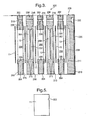
- FIG 3 there is shown a cross-sectional view through the structural components of a cell stack 200 corresponding to the arrangement of figure 2 , but with the components separated for clarity.
- the stack 200 consists of a stack of moulded plastic plates 202 and 206 arranged alternately.
- the plates 202 define a generally rectangular through-aperture 208 surrounded by a frame 204; the apertures 208 provide the electrolyte chambers 8; immediately surrounding the aperture 208 is a 5 mm wide portion 205 of the frame which projects 0.5 mm above the surface of the remaining part of the frame 204.
- the plates 206 are bipolar plates; they define rectangular blind recesses 207 and 209 on opposite faces, each recess being about 3 mm deep, surrounded by a frame 210 generally similar to the frame 204, but in which there is a 5 mm wide shallow recess 211 of depth 1.0 mm surrounding each recess.
- the blind recesses 207 and 209 provide the gas chambers 7 and 9.
- the apertures 208 may be filled with a loose mesh (not shown) to provide mechanical support for the electrodes 11 and 12.
- Electrodes 11 and 12 locate in the shallow recesses 211 on opposite sides of each bipolar plate 206, with the catalyst-carrying face of the electrode 11 or 12 facing the respective blind recess 207 or 209 respectively.
- gasket sealant 215 adheres to the frame 204 and dries to give a non-tacky outer surface, while remaining resilient.
- the components are then assembled as described, so that the raised portions 205 locate in the shallow recesses 211, securing the electrodes 11 and 12 in place.
- the sealant 215 ensures that electrolyte in the chambers 208 cannot leak out, and that gases cannot leak in, around the edges of the electrodes 11 and 12, and also ensures that gases cannot leak out between adjacent frames 204 and 210.
- the surfaces of the frames 210 of the bipolar plates 206, including the outer edge surface, are provided with a nickel coating, for example by electro-less deposition.
- This coating of nickel provides an electrical connection between an anode 11 on one side and a cathode 12 on the other side, so that the fuel cells 10 are connected in series with each other in the cell stack.
- This coating may alternatively be of other conducting materials.
- an end plate 230 which defines a blind recess 209 on one face but is blank on the outer face, and defines ports 232 communicating with the fluid flow ducts through which the gases and electrolyte flow to or from the stack 200, each port 232 comprising a cylindrical recess on the outer face of the end plate 230.
- an end plate 234 (see Figure 4 ) which defines a blind recess 207, but is blank on the outer face and does not define through apertures.
- the components are secured together for example using a strap 235 (shown partly broken away) around the entire stack 200.
- the closed end of the casing 240 defining projecting nozzles 242 which locale in and seal to the cylindrical ports 232 on the outer face of the end plate 230.
- the nozzles 242 may incorporate O-ring seals (not shown).
- Pipes 245 to carry the gases and electrolyte to or from the cell stack 200 communicate with these projecting nozzles 242 via ducts through the end of the casing 240.
- electrical connections 248 which project from the end plate 230 extend through corresponding apertures in the end of the casing 240.
- the open end of the casing 240 is then closed by a cap 250 which incorporates a pressure applying plate 252 to ensure that the stack 200 remains under compression despite expansion or contraction with temperature changes.
- the cap 250 is attached to the casing 240 by bolts 254.
- the casing 240 is of a moulded plastics material, and the external pipes 245 are integral with it.
- the electrodes 11 and 12 and the recesses 211 into which they locate may be shaped to ensure that the electrodes 11 or 12 cannot be inserted in the wrong orientation, for example as shown in Figure 5 the electrodes 11 may be rectangular with a cut-out 222 at one point around the periphery, there being a projection of complementary shape in the corresponding wall of the recess 211.
- the electrodes 11 and 12 are not mechanically bonded to the plates 202 and 206, which has a number of implications.
- electrodes 11 and 12 are readily separated from the rest of stack 200.
- the stack 200 is removed as described above from the system in which it is installed and it may be replaced by a previously overhauled stack 200; the system thus has little down-time.
- the used stack 200 is dismantled to replace the old electrodes 11, 12 so that it is ready for re-use. Consequently, replacement of the stack costs only the cost of the new electrodes (and labour costs for their installation). It may subsequently be possible to refurbish the old electrodes 11, 12 offsite.
- parts are arranged to be joined together or assembled in one orientation only. This is ensured for example by the cut-out 222 and complementary projection described above ( Fig. 5 ).
- the stack 200 must be held together by some other means; but this should be readily releasable, so that the stack 200 may be dismantled easily. This is ensured by for example the strap 235 ( Fig. 3 ).
- the pressure applying plate 252 may therefore incorporate a spring system.
- the spring system can either be in the form of a mechanical spring (for example, a helical, or leaf spring) or in the form of a suitable resilient plastic material.
Landscapes
- Chemical & Material Sciences (AREA)
- Engineering & Computer Science (AREA)
- General Chemical & Material Sciences (AREA)
- Electrochemistry (AREA)
- Chemical Kinetics & Catalysis (AREA)
- Sustainable Development (AREA)
- Sustainable Energy (AREA)
- Life Sciences & Earth Sciences (AREA)
- Manufacturing & Machinery (AREA)
- Materials Engineering (AREA)
- Composite Materials (AREA)
- Fuel Cell (AREA)
- Micro-Organisms Or Cultivation Processes Thereof (AREA)
Abstract
Description
- This invention relates to fuel cells.
- Fuel cells are a type of electrochemical energy conversion device. In contrast to a battery, fuel cells do not store all of the chemicals that are to be converted; rather, at least one of the chemicals is supplied externally, usually from a fuel tank. Consequently, fuel cells do not run out of (internal) chemicals and so do not become "dead", as batteries do. Fuel cells are known in a number of different varieties. Fuel cells based on hydrogen and oxygen are particularly common today. Fuel cells may be classified according to their electrolyte, for example alkaline fuel cells (AFCs), phosphoric-acid fuel cells (PAFCs), solid oxide fuel cells (SOFCs) and molten carbonate fuel cells (MCFCs).
- Alkaline fuel cells are of particular interest because they operate at relatively low temperatures and pressures, are efficient and rugged. Acid fuel cells and fuel cells employing other aqueous electrolytes are also of interest. Such fuel cells typically comprise an electrolyte chamber separated from a fuel gas chamber (containing a fuel gas, typically hydrogen) and a further fuel gas chamber (containing an oxidant gas, usually air). The electrolyte chamber is separated from the gas chambers using electrodes. The standard electrodes for alkaline fuel cells comprise a conductive metal grid or mesh backbone, typically nickel, that provides a mechanical strength to the electrode. Onto the metal mesh or grid is deposited a slurry or dispersion of particulate poly tetra-fluoroethylene (PTFE), activated carbon and a catalyst metal, typically platinum.
- Whilst use of alkaline fuel cells in the present invention is preferred, the invention is not limited to alkaline fuel cells but rather is suitable for other kinds of fuel cells, particularly those that operate at relatively low temperatures (say less than 100°C).
- Fuel cells typically comprise at least two electrodes fixed to plates or frames, which are typically plastic, and which are typically moulded together to form a stack. The stack has inlets and outlets for fuels and waste products, respectively. After a period of use the performance of the stack will deteriorate due to deterioration of the electrodes, which may become corroded. The stack is then thrown away and replaced with a new stack.
- According to a first aspect of the invention there is provided a fuel-cell assembly according to claim 1.
- Fuel-cell electrodes are relatively low-cost, compared with other parts of the fuel cell stack. When the electrodes are moulded into a stack, the whole stack must be disposed of as a single unit when electrodes have deteriorated to the point at which they need replacing. By providing electrodes that are held loosely within the stack, the invention allows replacement of the electrodes, whilst allowing reuse of the other parts of the stack. The invention may therefore provide electrodes that are "loose", in the sense that they can readily be removed from the stack and replaced. Since the stack may be disassembled, its constituent parts may be recycled or disposed of individually.
- The electrodes may be of a shape complementary to the shape of the frame in which they are held, the shapes being such that the electrodes can be held only in one orientation. Allowing the electrodes to be installed in only one orientation eliminates the possibility of installing new electrodes in an incorrect orientation when old electrodes are replaced.
- In a preferred embodiment the electrodes comprise: a substrate comprising a relatively hydrophilic plastics material, the substrate being permeable to aqueous fuel cell electrolytes; a conductive layer comprising a substantially uniform layer of conductive metal; and a catalyst layer. These layers may be discrete superimposed layers. Electrodes of that form are described in a PCT Patent Application by the same applicant
PCT/GB2007/050104 - The stack may further comprise a monitor for monitoring the electrodes to determine when they need to be replaced. For a given power output, the current output from the stack is typically substantially fixed. Thus, the voltage may be monitored and, when the voltage falls below a predetermined value, a decision may be made to replace the electrode.
- The clamp may comprise a resilient member. Use of a resilient member allows the stack to expand or contract with temperature changes without the clamping of the components being compromised. The clamp may comprise a strap strapped around the stack. The end plates of the stack which are in contact with the strap may be larger than the frames of the stack. The strap may be seated in a groove. The strap may be made from a material that expands and contracts with changes in temperature by an amount sufficient to prevent the clamping of the walls and electrodes from being compromised. There may be a plurality of straps.
- The clamp may further comprise a cam and lever system arranged to apply a force to the straps and hence to retain the cell stack components together.
- The invention will now be further described, by way of example only, with reference to the accompanying drawings in which:
-
Figure 1 is a schematic cross-section of an electrode for use in a fuel cell stack; -
Figure 2 is a schematic cross-section of a fuel cell stack incorporating an electrode ofFigure 1 ; -
Figure 3 shows a cross-sectional view of components forming a fuel cell stack, with the components separated for clarity; -
Figure 4 shows a cross-sectional view of a cell stack as infigure 3 , after insertion into a casing; and -
Figure 5 shows a plan view of an anode from the stack offigure 3 . - Referring now to
Figure 1 , anelectrode 10 is built up of three main parts: a porous substrate 1, a conductivelayer comprising layers optional layer 4 of protective material, and acatalyst layer 5. - In each of the examples the substrate 1 is a microporous sheet of polypropylene plastics material (SciMAT 700/70), which is hydrophilic and has an approximate thickness of between 100 to 400 µm, such as 125 µm, and a bubble point of between 8.0 to 15.0 kPa gauge. This material has a wicking rate of 90 mm per 600 seconds.
- A 0.5 µm layer of silver is electro-less plated onto the substrate 1 to form a
first layer 2 of conductive material. Asecond layer 3 of silver ofthickness 3 µm is then electroplated onto thefirst layer 2 of conductive material. A protective 0.05 µmthick layer 4 of rhodium is then electroplated onto thesecond layer 3 of conductive material to complete the conductive layer structure. - A 0.5 µm layer of silver is electro-less plated onto the substrate 1 to form a
first layer 2 of conductive material, followed by electroplating copper to form asecond layer 3 ofthickness 5 µm of conductive material, followed by electroplating aprotective layer 4 of nickel, 1 µm thick. - A 0.5
µm layer 2 of silver is electro-less plated onto the substrate 1 to form a first layer of conductive material, followed by electroplating 5 µm thickness of nickel to form asecond layer 3 of conductive material. - The example catalyst mixtures for both cathode and anode electrodes use a combination of catalyst, binder and solvent which are spray-coated onto the conductor layers of Examples 1, 2 and 3 above. The binder may for example be polyethylene (such as PE1020 from Exxon-Mobil), and the solvent isododecane. Percentage weights refer to the total mass of the dry materials before the addition of a suitable solvent.
- The cathode catalyst mixtures A to C below include an oxygen reduction catalyst.
- A. Activated carbon, with 10% binder and solvent.
- B. 10% Pd/Pt on activated carbons with 10% binder + solvent.
- C. Silver on activated carbon, with 10% binder + solvent.
The anode catalyst mixtures D and E below include a hydrogen oxidation catalyst. - D. Nickel-aluminum alloy powder with activated carbon, with 10% binder and solvent.
- E. 10% Pd/Pt on activated carbon, with 10% binder + solvent.
- Referring now to
figure 2 , afuel cell 20 comprises twoelectrodes catalyst layer 5 and the other is the substrate layer 1, as described in relation tofigure 1 above. Theanode 11 and cathode 12 (which may differ in the nature of therespective catalyst layer 5, as described above) are mutually spaced so as to form an electrolyte chamber 8 between them. Ahydrogen gas chamber 7 for hydrogen gas is provided on the opposite side of theanode 11 from the electrolyte chamber 8, and anoxygen gas chamber 9 for air is provided on the opposite of thecathode 12. The catalyst side of each of the anode andcathode 11, 12 (i.e. the side with the catalyst layer 5) is exposed to the gas chambers, so the substrate side (i.e. the side that is not provided with a catalyst layer) is exposed to the electrolyte chamber 8. - On the other side of the
gas chambers bipolar plate 6 that separates agas chamber further gas chamber adjacent fuel cell 20. - Referring now to
figure 3 there is shown a cross-sectional view through the structural components of acell stack 200 corresponding to the arrangement offigure 2 , but with the components separated for clarity. Thestack 200 consists of a stack of mouldedplastic plates plates 202 define a generally rectangular through-aperture 208 surrounded by aframe 204; theapertures 208 provide the electrolyte chambers 8; immediately surrounding theaperture 208 is a 5 mmwide portion 205 of the frame which projects 0.5 mm above the surface of the remaining part of theframe 204. Theplates 206 are bipolar plates; they define rectangularblind recesses frame 210 generally similar to theframe 204, but in which there is a 5 mm wideshallow recess 211 of depth 1.0 mm surrounding each recess. Theblind recesses gas chambers apertures 208 may be filled with a loose mesh (not shown) to provide mechanical support for theelectrodes -
Electrodes shallow recesses 211 on opposite sides of eachbipolar plate 206, with the catalyst-carrying face of theelectrode blind recess gasket sealant 215; this adheres to theframe 204 and dries to give a non-tacky outer surface, while remaining resilient. The components are then assembled as described, so that the raisedportions 205 locate in theshallow recesses 211, securing theelectrodes sealant 215 ensures that electrolyte in thechambers 208 cannot leak out, and that gases cannot leak in, around the edges of theelectrodes adjacent frames - The surfaces of the
frames 210 of thebipolar plates 206, including the outer edge surface, are provided with a nickel coating, for example by electro-less deposition. This coating of nickel provides an electrical connection between ananode 11 on one side and acathode 12 on the other side, so that thefuel cells 10 are connected in series with each other in the cell stack. This coating may alternatively be of other conducting materials. - The flow of electrolyte to and from the electrolyte chambers (apertures 208), and the flows of the gases to and from the gas chambers (
recesses 207 and 209), follow respective fluid flow ducts defined by aligned apertures through theplates apertures apertures electrolyte chambers 208 via narrowertransverse ducts 220. Thesealant 215 is placed so as not to block theapertures 216. At one end of thestack 200 is anend plate 230 which defines ablind recess 209 on one face but is blank on the outer face, and definesports 232 communicating with the fluid flow ducts through which the gases and electrolyte flow to or from thestack 200, eachport 232 comprising a cylindrical recess on the outer face of theend plate 230. At the other end is an end plate 234 (seeFigure 4 ) which defines ablind recess 207, but is blank on the outer face and does not define through apertures. - After assembly of the
stack 200 the components are secured together for example using a strap 235 (shown partly broken away) around theentire stack 200. - Referring now to
figure 4 , after assembly thestack 200 is then inserted into acasing 240, the closed end of thecasing 240 defining projectingnozzles 242 which locale in and seal to thecylindrical ports 232 on the outer face of theend plate 230. Thenozzles 242 may incorporate O-ring seals (not shown).Pipes 245 to carry the gases and electrolyte to or from thecell stack 200 communicate with these projectingnozzles 242 via ducts through the end of thecasing 240. In addiction,electrical connections 248 which project from theend plate 230 extend through corresponding apertures in the end of thecasing 240. The open end of thecasing 240 is then closed by acap 250 which incorporates apressure applying plate 252 to ensure that thestack 200 remains under compression despite expansion or contraction with temperature changes. In this example thecap 250 is attached to thecasing 240 bybolts 254. In one embodiment thecasing 240 is of a moulded plastics material, and theexternal pipes 245 are integral with it. - If it is subsequently necessary to replace one of the
electrodes cap 250, withdrawing thestack 200, and undoing the strap 235 (not shown inFigure 4 ), by separating theplates electrode gasket material 215 can be peeled off the surface of theplate 202, andfresh gasket material 215 deposited. Theelectrodes recesses 211 into which they locate may be shaped to ensure that theelectrodes Figure 5 theelectrodes 11 may be rectangular with a cut-out 222 at one point around the periphery, there being a projection of complementary shape in the corresponding wall of therecess 211. - The
electrodes plates electrodes stack 200. When theelectrodes stack 200 is removed as described above from the system in which it is installed and it may be replaced by a previously overhauledstack 200; the system thus has little down-time. The usedstack 200 is dismantled to replace theold electrodes old electrodes - Second, the lack of mechanical bonding means that accurate assembly of
stack 200 is particularly important, as there are more parts to be correctly located. In order to aid accurate assembly, parts are arranged to be joined together or assembled in one orientation only. This is ensured for example by the cut-out 222 and complementary projection described above (Fig. 5 ). - Third, as the
electrodes plates stack 200 must be held together by some other means; but this should be readily releasable, so that thestack 200 may be dismantled easily. This is ensured by for example the strap 235 (Fig. 3 ). - During operation the clamping force holding the stack together must be sufficient to prevent any fluid leakage, despite variations in the length of the stack as its temperature varies. The
pressure applying plate 252 may therefore incorporate a spring system. The spring system can either be in the form of a mechanical spring (for example, a helical, or leaf spring) or in the form of a suitable resilient plastic material.
Claims (9)
- A fuel cell assembly comprising: (a) a fuel cell stack comprising a plurality of fuel cells, each fuel cell comprising two electrodes that are mutually spaced so as to form an electrolyte chamber therebetween, a first gas chamber for a first gas being provided on the opposite side of a first electrode from the electrolyte chamber, and a second gas chamber for a second gas being provided on the opposite of a second electrode from the electrolyte chamber, and each electrode incorporating a catalyst; the fuel cell stack incorporating electrolyte chamber frames to define the electrolyte chambers and gas chamber frames to define the gas chambers, the electrodes being sealingly secured between the electrolyte chamber frames and the gas chamber frames; and at least one end plate defining ports to supply or withdraw fluids from the fuel cells;(b) a releasable clamp to retain the components of the fuel cell stack; and(c) a casing into which the fuel cell stack is insertable, the casing providing compression means to compress the fuel cell stack components together;(d) in which the fuel cell stack and the closed end of the casing define mating plugs and sockets for supply of electrolyte and gases to or from the fuel cell stack.
- A fuel cell assembly as claimed in claim 1, in which the electrodes are of a shape complementary to the shape of the frame in which they locate, and the shapes are such that the electrodes can be held only in one orientation.
- A fuel cell assembly as claimed in any preceding claim, in which the electrode comprises: a substrate comprising a relatively hydrophilic plastics material, the substrate being permeable to aqueous fuel cell electrolytes; a conductive layer comprising a substantially uniform layer of conductive metal; and a catalyst layer.
- A fuel cell assembly as claimed in any one of the preceding claims wherein the electrodes are readily removable from the fuel cell stack.
- A fuel cell assembly as claimed in any one of the preceding claims, further comprising a monitor for monitoring the electrodes to determine when they need to be replaced.
- A fuel cell assembly as claimed in any one of the preceding claims wherein the casing is of a moulded plastics material.
- A fuel cell assembly as claimed in any one of the preceding claims wherein fluid flow pipes for supply of electrolyte or gas to or from the stack are integral with the casing.
- A fuel cell assembly as claimed in any one of the preceding claims wherein the casing incorporates a resilient element which allows the stack to expand or contract with temperature changes without the clamping of the plates and electrodes being compromised.
- A fuel cell assembly as claimed in any one of the preceding claims, in which the clamp comprises a strap strapped around the stack.
Applications Claiming Priority (2)
| Application Number | Priority Date | Filing Date | Title |
|---|---|---|---|
| GBGB0604598.3A GB0604598D0 (en) | 2006-03-07 | 2006-03-07 | Improvements in and relating to fuel cells |
| PCT/GB2007/050106 WO2007102028A1 (en) | 2006-03-07 | 2007-03-07 | Fuel cell assembly |
Publications (2)
| Publication Number | Publication Date |
|---|---|
| EP1992031A1 EP1992031A1 (en) | 2008-11-19 |
| EP1992031B1 true EP1992031B1 (en) | 2011-09-14 |
Family
ID=36241148
Family Applications (1)
| Application Number | Title | Priority Date | Filing Date |
|---|---|---|---|
| EP07712985A Not-in-force EP1992031B1 (en) | 2006-03-07 | 2007-03-07 | Fuel cell assembly |
Country Status (5)
| Country | Link |
|---|---|
| US (1) | US20090197149A1 (en) |
| EP (1) | EP1992031B1 (en) |
| AT (1) | ATE524845T1 (en) |
| GB (1) | GB0604598D0 (en) |
| WO (1) | WO2007102028A1 (en) |
Families Citing this family (6)
| Publication number | Priority date | Publication date | Assignee | Title |
|---|---|---|---|---|
| EP1992030A2 (en) | 2006-03-07 | 2008-11-19 | AFC Energy PLC | Electrodes of a fuel cell |
| JP5751884B2 (en) | 2011-03-29 | 2015-07-22 | 森永乳業株式会社 | Bipolar electrolytic cell |
| DE102014006027A1 (en) | 2014-04-25 | 2015-10-29 | Daimler Ag | A fuel cell assembly |
| SE544014C2 (en) * | 2018-06-26 | 2021-11-02 | Powercell Sweden Ab | Manufacturing arrangement for a fuel cell stack and method for manufactur-ing a fuel cell stack |
| CN111628199B (en) * | 2020-05-29 | 2024-04-09 | 江苏大学 | Sectional type fuel cell fixture |
| GB202100553D0 (en) | 2021-01-15 | 2021-03-03 | Afc Energy Plc | Alkaline fuel cell stack with recirculating electrolyte system |
Family Cites Families (22)
| Publication number | Priority date | Publication date | Assignee | Title |
|---|---|---|---|---|
| DE1239375B (en) * | 1962-09-12 | 1967-04-27 | Siemens Ag | Method for operating a fuel element and device for carrying out the method |
| US3926676A (en) * | 1971-02-25 | 1975-12-16 | Siemens Ag | Battery comprising a plurality of cells |
| US3912538A (en) * | 1974-01-15 | 1975-10-14 | United Technologies Corp | Novel composite fuel cell electrode |
| JPS5893173A (en) * | 1981-11-26 | 1983-06-02 | Toshiba Corp | Fuel cell stack clamping apparatus |
| US4444852A (en) * | 1982-08-27 | 1984-04-24 | The United States Of America As Represented By The United States Department Of Energy | Size and weight graded multi-ply laminar electrodes |
| JPS59184469A (en) * | 1983-04-01 | 1984-10-19 | Hitachi Ltd | Fuel cell |
| JPS60124367A (en) * | 1983-12-08 | 1985-07-03 | Agency Of Ind Science & Technol | Electrolyte circulation system of fuel cell |
| JPS63178455A (en) * | 1987-01-19 | 1988-07-22 | Fuji Electric Co Ltd | Free electrolyte type fuel cell |
| JPH0393167A (en) * | 1989-09-04 | 1991-04-18 | Fuji Electric Co Ltd | Side lamination type fuel battery stack and its module construction |
| US5480735A (en) * | 1990-06-25 | 1996-01-02 | International Fuel Cells Corporation | High current alkaline fuel cell electrodes |
| US5789091C1 (en) * | 1996-11-19 | 2001-02-27 | Ballard Power Systems | Electrochemical fuel cell stack with compression bands |
| US6232008B1 (en) * | 1997-07-16 | 2001-05-15 | Ballard Power Systems Inc. | Electrochemical fuel cell stack with improved reactant manifolding and sealing |
| US6040072A (en) * | 1997-11-19 | 2000-03-21 | Lynntech, Inc. | Apparatus and method for compressing a stack of electrochemical cells |
| US6218039B1 (en) * | 1999-08-25 | 2001-04-17 | Plug Power, Inc. | Clamping apparatus and method for a fuel cell |
| US20030207156A1 (en) * | 2000-10-13 | 2003-11-06 | Ovshinsky Stanford R. | Very low emission hybrid electric vehicle incorporating an integrated propulsion system including a fuel cell and a high power nickel metal hydride battery pack |
| US20020155341A1 (en) * | 2001-04-19 | 2002-10-24 | More Energy Ltd. | Self-managing electrochemical fuel cell and fuel cell anode |
| US20030198862A1 (en) * | 2002-04-19 | 2003-10-23 | Enernext | Liquid gallium alkaline electrolyte fuel cell |
| US6989216B2 (en) * | 2002-04-29 | 2006-01-24 | Texaco Ovonic Fuel Cell Llc | Fuel cell with overmolded electrode assemblies |
| US6869709B2 (en) * | 2002-12-04 | 2005-03-22 | Utc Fuel Cells, Llc | Fuel cell system with improved humidification system |
| CA2523462C (en) * | 2003-04-22 | 2013-09-24 | Benedetto Anthony Iacovelli | Fuel cell, components and systems |
| US7241526B2 (en) * | 2004-03-16 | 2007-07-10 | Utc Power Corporation | Fuel cell manifold cable end clamp |
| US8221936B2 (en) * | 2005-04-14 | 2012-07-17 | GM Global Technology Operations LLC | Method and apparatus for attachment of fuel cell stack manifold |
-
2006
- 2006-03-07 GB GBGB0604598.3A patent/GB0604598D0/en not_active Ceased
-
2007
- 2007-03-07 US US12/281,757 patent/US20090197149A1/en not_active Abandoned
- 2007-03-07 EP EP07712985A patent/EP1992031B1/en not_active Not-in-force
- 2007-03-07 AT AT07712985T patent/ATE524845T1/en not_active IP Right Cessation
- 2007-03-07 WO PCT/GB2007/050106 patent/WO2007102028A1/en not_active Ceased
Also Published As
| Publication number | Publication date |
|---|---|
| US20090197149A1 (en) | 2009-08-06 |
| GB0604598D0 (en) | 2006-04-19 |
| ATE524845T1 (en) | 2011-09-15 |
| EP1992031A1 (en) | 2008-11-19 |
| WO2007102028A1 (en) | 2007-09-13 |
Similar Documents
| Publication | Publication Date | Title |
|---|---|---|
| JP4742043B2 (en) | Membrane electrode assembly with integral seal | |
| EP1992031B1 (en) | Fuel cell assembly | |
| EP2885834B1 (en) | Design of bipolar plates for use in electrochemical cells | |
| EP2878028B1 (en) | Arrangement of flow structures for use in high differential pressure electrochemical cells | |
| CA2460241A1 (en) | Modular fuel cell cartridge and stack | |
| KR20010022355A (en) | Polymer electrolyte fuel cell and method of manufacture thereof | |
| US7985505B2 (en) | Fuel cell apparatus and associated method | |
| US20090301868A1 (en) | Methods and systems for assembling electrolyzer stacks | |
| US7186476B2 (en) | One piece bipolar plate with spring seals | |
| US10283784B2 (en) | Fuel cell for detecting a pollutant | |
| US20050263393A1 (en) | System and method of performing electrochemical tests of solid oxide fuel cells | |
| TW201608755A (en) | Apparatus and method related to recombiner fuel cell | |
| JP5230174B2 (en) | Fuel cell | |
| EP1195831A1 (en) | Polymer electrolyte fuel cell and its usage | |
| JP5188459B2 (en) | Fuel cell stack | |
| JPH0837012A (en) | Solid polymer electrolyte fuel cell | |
| WO2011039523A1 (en) | Cell stack | |
| US8911916B2 (en) | Fuel cell | |
| US11600830B2 (en) | Plate member for a cell stack | |
| CA2466369A1 (en) | Method for reusing current collectors/distributors of solid polymer electrolyte fuel cell stacks | |
| US20040214067A1 (en) | Assembling sub-stacks of electrochemical cells | |
| EP3590144B1 (en) | Novel modular electrochemical cell and stack design | |
| JP5378049B2 (en) | Fuel cell stack | |
| JP6389959B2 (en) | Fuel cell stack and fuel cell stack manufacturing method | |
| JP4848824B2 (en) | Polymer electrolyte fuel cell |
Legal Events
| Date | Code | Title | Description |
|---|---|---|---|
| PUAI | Public reference made under article 153(3) epc to a published international application that has entered the european phase |
Free format text: ORIGINAL CODE: 0009012 |
|
| 17P | Request for examination filed |
Effective date: 20080902 |
|
| AK | Designated contracting states |
Kind code of ref document: A1 Designated state(s): AT BE BG CH CY CZ DE DK EE ES FI FR GB GR HU IE IS IT LI LT LU LV MC MT NL PL PT RO SE SI SK TR |
|
| 17Q | First examination report despatched |
Effective date: 20100203 |
|
| GRAP | Despatch of communication of intention to grant a patent |
Free format text: ORIGINAL CODE: EPIDOSNIGR1 |
|
| DAX | Request for extension of the european patent (deleted) | ||
| GRAS | Grant fee paid |
Free format text: ORIGINAL CODE: EPIDOSNIGR3 |
|
| GRAA | (expected) grant |
Free format text: ORIGINAL CODE: 0009210 |
|
| AK | Designated contracting states |
Kind code of ref document: B1 Designated state(s): AT BE BG CH CY CZ DE DK EE ES FI FR GB GR HU IE IS IT LI LT LU LV MC MT NL PL PT RO SE SI SK TR |
|
| REG | Reference to a national code |
Ref country code: GB Ref legal event code: FG4D |
|
| REG | Reference to a national code |
Ref country code: CH Ref legal event code: EP |
|
| REG | Reference to a national code |
Ref country code: IE Ref legal event code: FG4D |
|
| REG | Reference to a national code |
Ref country code: DE Ref legal event code: R096 Ref document number: 602007017171 Country of ref document: DE Effective date: 20111208 |
|
| REG | Reference to a national code |
Ref country code: NL Ref legal event code: VDEP Effective date: 20110914 |
|
| PG25 | Lapsed in a contracting state [announced via postgrant information from national office to epo] |
Ref country code: FI Free format text: LAPSE BECAUSE OF FAILURE TO SUBMIT A TRANSLATION OF THE DESCRIPTION OR TO PAY THE FEE WITHIN THE PRESCRIBED TIME-LIMIT Effective date: 20110914 Ref country code: SE Free format text: LAPSE BECAUSE OF FAILURE TO SUBMIT A TRANSLATION OF THE DESCRIPTION OR TO PAY THE FEE WITHIN THE PRESCRIBED TIME-LIMIT Effective date: 20110914 Ref country code: LT Free format text: LAPSE BECAUSE OF FAILURE TO SUBMIT A TRANSLATION OF THE DESCRIPTION OR TO PAY THE FEE WITHIN THE PRESCRIBED TIME-LIMIT Effective date: 20110914 |
|
| LTIE | Lt: invalidation of european patent or patent extension |
Effective date: 20110914 |
|
| PG25 | Lapsed in a contracting state [announced via postgrant information from national office to epo] |
Ref country code: GR Free format text: LAPSE BECAUSE OF FAILURE TO SUBMIT A TRANSLATION OF THE DESCRIPTION OR TO PAY THE FEE WITHIN THE PRESCRIBED TIME-LIMIT Effective date: 20111215 Ref country code: LV Free format text: LAPSE BECAUSE OF FAILURE TO SUBMIT A TRANSLATION OF THE DESCRIPTION OR TO PAY THE FEE WITHIN THE PRESCRIBED TIME-LIMIT Effective date: 20110914 Ref country code: AT Free format text: LAPSE BECAUSE OF FAILURE TO SUBMIT A TRANSLATION OF THE DESCRIPTION OR TO PAY THE FEE WITHIN THE PRESCRIBED TIME-LIMIT Effective date: 20110914 Ref country code: SI Free format text: LAPSE BECAUSE OF FAILURE TO SUBMIT A TRANSLATION OF THE DESCRIPTION OR TO PAY THE FEE WITHIN THE PRESCRIBED TIME-LIMIT Effective date: 20110914 Ref country code: CY Free format text: LAPSE BECAUSE OF FAILURE TO SUBMIT A TRANSLATION OF THE DESCRIPTION OR TO PAY THE FEE WITHIN THE PRESCRIBED TIME-LIMIT Effective date: 20110914 |
|
| REG | Reference to a national code |
Ref country code: AT Ref legal event code: MK05 Ref document number: 524845 Country of ref document: AT Kind code of ref document: T Effective date: 20110914 |
|
| PG25 | Lapsed in a contracting state [announced via postgrant information from national office to epo] |
Ref country code: BE Free format text: LAPSE BECAUSE OF FAILURE TO SUBMIT A TRANSLATION OF THE DESCRIPTION OR TO PAY THE FEE WITHIN THE PRESCRIBED TIME-LIMIT Effective date: 20110914 |
|
| PG25 | Lapsed in a contracting state [announced via postgrant information from national office to epo] |
Ref country code: SK Free format text: LAPSE BECAUSE OF FAILURE TO SUBMIT A TRANSLATION OF THE DESCRIPTION OR TO PAY THE FEE WITHIN THE PRESCRIBED TIME-LIMIT Effective date: 20110914 Ref country code: IS Free format text: LAPSE BECAUSE OF FAILURE TO SUBMIT A TRANSLATION OF THE DESCRIPTION OR TO PAY THE FEE WITHIN THE PRESCRIBED TIME-LIMIT Effective date: 20120114 Ref country code: CZ Free format text: LAPSE BECAUSE OF FAILURE TO SUBMIT A TRANSLATION OF THE DESCRIPTION OR TO PAY THE FEE WITHIN THE PRESCRIBED TIME-LIMIT Effective date: 20110914 |
|
| PG25 | Lapsed in a contracting state [announced via postgrant information from national office to epo] |
Ref country code: PT Free format text: LAPSE BECAUSE OF FAILURE TO SUBMIT A TRANSLATION OF THE DESCRIPTION OR TO PAY THE FEE WITHIN THE PRESCRIBED TIME-LIMIT Effective date: 20120116 Ref country code: IT Free format text: LAPSE BECAUSE OF FAILURE TO SUBMIT A TRANSLATION OF THE DESCRIPTION OR TO PAY THE FEE WITHIN THE PRESCRIBED TIME-LIMIT Effective date: 20110914 Ref country code: EE Free format text: LAPSE BECAUSE OF FAILURE TO SUBMIT A TRANSLATION OF THE DESCRIPTION OR TO PAY THE FEE WITHIN THE PRESCRIBED TIME-LIMIT Effective date: 20110914 Ref country code: NL Free format text: LAPSE BECAUSE OF FAILURE TO SUBMIT A TRANSLATION OF THE DESCRIPTION OR TO PAY THE FEE WITHIN THE PRESCRIBED TIME-LIMIT Effective date: 20110914 Ref country code: PL Free format text: LAPSE BECAUSE OF FAILURE TO SUBMIT A TRANSLATION OF THE DESCRIPTION OR TO PAY THE FEE WITHIN THE PRESCRIBED TIME-LIMIT Effective date: 20110914 Ref country code: RO Free format text: LAPSE BECAUSE OF FAILURE TO SUBMIT A TRANSLATION OF THE DESCRIPTION OR TO PAY THE FEE WITHIN THE PRESCRIBED TIME-LIMIT Effective date: 20110914 |
|
| PLBE | No opposition filed within time limit |
Free format text: ORIGINAL CODE: 0009261 |
|
| STAA | Information on the status of an ep patent application or granted ep patent |
Free format text: STATUS: NO OPPOSITION FILED WITHIN TIME LIMIT |
|
| PG25 | Lapsed in a contracting state [announced via postgrant information from national office to epo] |
Ref country code: DK Free format text: LAPSE BECAUSE OF FAILURE TO SUBMIT A TRANSLATION OF THE DESCRIPTION OR TO PAY THE FEE WITHIN THE PRESCRIBED TIME-LIMIT Effective date: 20110914 |
|
| 26N | No opposition filed |
Effective date: 20120615 |
|
| REG | Reference to a national code |
Ref country code: DE Ref legal event code: R097 Ref document number: 602007017171 Country of ref document: DE Effective date: 20120615 |
|
| PG25 | Lapsed in a contracting state [announced via postgrant information from national office to epo] |
Ref country code: MC Free format text: LAPSE BECAUSE OF NON-PAYMENT OF DUE FEES Effective date: 20120331 |
|
| REG | Reference to a national code |
Ref country code: CH Ref legal event code: PL |
|
| REG | Reference to a national code |
Ref country code: FR Ref legal event code: ST Effective date: 20121130 |
|
| REG | Reference to a national code |
Ref country code: IE Ref legal event code: MM4A |
|
| PG25 | Lapsed in a contracting state [announced via postgrant information from national office to epo] |
Ref country code: FR Free format text: LAPSE BECAUSE OF NON-PAYMENT OF DUE FEES Effective date: 20120402 Ref country code: CH Free format text: LAPSE BECAUSE OF NON-PAYMENT OF DUE FEES Effective date: 20120331 Ref country code: IE Free format text: LAPSE BECAUSE OF NON-PAYMENT OF DUE FEES Effective date: 20120307 Ref country code: LI Free format text: LAPSE BECAUSE OF NON-PAYMENT OF DUE FEES Effective date: 20120331 |
|
| PG25 | Lapsed in a contracting state [announced via postgrant information from national office to epo] |
Ref country code: ES Free format text: LAPSE BECAUSE OF FAILURE TO SUBMIT A TRANSLATION OF THE DESCRIPTION OR TO PAY THE FEE WITHIN THE PRESCRIBED TIME-LIMIT Effective date: 20111225 |
|
| PG25 | Lapsed in a contracting state [announced via postgrant information from national office to epo] |
Ref country code: BG Free format text: LAPSE BECAUSE OF FAILURE TO SUBMIT A TRANSLATION OF THE DESCRIPTION OR TO PAY THE FEE WITHIN THE PRESCRIBED TIME-LIMIT Effective date: 20111214 |
|
| PG25 | Lapsed in a contracting state [announced via postgrant information from national office to epo] |
Ref country code: MT Free format text: LAPSE BECAUSE OF FAILURE TO SUBMIT A TRANSLATION OF THE DESCRIPTION OR TO PAY THE FEE WITHIN THE PRESCRIBED TIME-LIMIT Effective date: 20110914 |
|
| PG25 | Lapsed in a contracting state [announced via postgrant information from national office to epo] |
Ref country code: TR Free format text: LAPSE BECAUSE OF FAILURE TO SUBMIT A TRANSLATION OF THE DESCRIPTION OR TO PAY THE FEE WITHIN THE PRESCRIBED TIME-LIMIT Effective date: 20110914 |
|
| PG25 | Lapsed in a contracting state [announced via postgrant information from national office to epo] |
Ref country code: LU Free format text: LAPSE BECAUSE OF NON-PAYMENT OF DUE FEES Effective date: 20120307 |
|
| PG25 | Lapsed in a contracting state [announced via postgrant information from national office to epo] |
Ref country code: HU Free format text: LAPSE BECAUSE OF FAILURE TO SUBMIT A TRANSLATION OF THE DESCRIPTION OR TO PAY THE FEE WITHIN THE PRESCRIBED TIME-LIMIT Effective date: 20070307 |
|
| P01 | Opt-out of the competence of the unified patent court (upc) registered |
Effective date: 20230629 |
|
| PGFP | Annual fee paid to national office [announced via postgrant information from national office to epo] |
Ref country code: DE Payment date: 20240318 Year of fee payment: 18 Ref country code: GB Payment date: 20240315 Year of fee payment: 18 |
|
| REG | Reference to a national code |
Ref country code: DE Ref legal event code: R119 Ref document number: 602007017171 Country of ref document: DE |
|
| GBPC | Gb: european patent ceased through non-payment of renewal fee |
Effective date: 20250307 |
|
| PG25 | Lapsed in a contracting state [announced via postgrant information from national office to epo] |
Ref country code: DE Free format text: LAPSE BECAUSE OF NON-PAYMENT OF DUE FEES Effective date: 20251001 |
|
| PG25 | Lapsed in a contracting state [announced via postgrant information from national office to epo] |
Ref country code: GB Free format text: LAPSE BECAUSE OF NON-PAYMENT OF DUE FEES Effective date: 20250307 |