EP1991939B1 - Software and methods for dental treatment planning - Google Patents
Software and methods for dental treatment planning Download PDFInfo
- Publication number
- EP1991939B1 EP1991939B1 EP07757629.6A EP07757629A EP1991939B1 EP 1991939 B1 EP1991939 B1 EP 1991939B1 EP 07757629 A EP07757629 A EP 07757629A EP 1991939 B1 EP1991939 B1 EP 1991939B1
- Authority
- EP
- European Patent Office
- Prior art keywords
- teeth
- tooth
- user
- movement
- curve
- Prior art date
- Legal status (The legal status is an assumption and is not a legal conclusion. Google has not performed a legal analysis and makes no representation as to the accuracy of the status listed.)
- Active
Links
Images


Classifications
-
- A—HUMAN NECESSITIES
- A61—MEDICAL OR VETERINARY SCIENCE; HYGIENE
- A61C—DENTISTRY; APPARATUS OR METHODS FOR ORAL OR DENTAL HYGIENE
- A61C7/00—Orthodontics, i.e. obtaining or maintaining the desired position of teeth, e.g. by straightening, evening, regulating, separating, or by correcting malocclusions
- A61C7/002—Orthodontic computer assisted systems
-
- G—PHYSICS
- G16—INFORMATION AND COMMUNICATION TECHNOLOGY [ICT] SPECIALLY ADAPTED FOR SPECIFIC APPLICATION FIELDS
- G16H—HEALTHCARE INFORMATICS, i.e. INFORMATION AND COMMUNICATION TECHNOLOGY [ICT] SPECIALLY ADAPTED FOR THE HANDLING OR PROCESSING OF MEDICAL OR HEALTHCARE DATA
- G16H40/00—ICT specially adapted for the management or administration of healthcare resources or facilities; ICT specially adapted for the management or operation of medical equipment or devices
- G16H40/60—ICT specially adapted for the management or administration of healthcare resources or facilities; ICT specially adapted for the management or operation of medical equipment or devices for the operation of medical equipment or devices
- G16H40/63—ICT specially adapted for the management or administration of healthcare resources or facilities; ICT specially adapted for the management or operation of medical equipment or devices for the operation of medical equipment or devices for local operation
-
- G—PHYSICS
- G16—INFORMATION AND COMMUNICATION TECHNOLOGY [ICT] SPECIALLY ADAPTED FOR SPECIFIC APPLICATION FIELDS
- G16H—HEALTHCARE INFORMATICS, i.e. INFORMATION AND COMMUNICATION TECHNOLOGY [ICT] SPECIALLY ADAPTED FOR THE HANDLING OR PROCESSING OF MEDICAL OR HEALTHCARE DATA
- G16H50/00—ICT specially adapted for medical diagnosis, medical simulation or medical data mining; ICT specially adapted for detecting, monitoring or modelling epidemics or pandemics
- G16H50/50—ICT specially adapted for medical diagnosis, medical simulation or medical data mining; ICT specially adapted for detecting, monitoring or modelling epidemics or pandemics for simulation or modelling of medical disorders
-
- Y—GENERAL TAGGING OF NEW TECHNOLOGICAL DEVELOPMENTS; GENERAL TAGGING OF CROSS-SECTIONAL TECHNOLOGIES SPANNING OVER SEVERAL SECTIONS OF THE IPC; TECHNICAL SUBJECTS COVERED BY FORMER USPC CROSS-REFERENCE ART COLLECTIONS [XRACs] AND DIGESTS
- Y02—TECHNOLOGIES OR APPLICATIONS FOR MITIGATION OR ADAPTATION AGAINST CLIMATE CHANGE
- Y02A—TECHNOLOGIES FOR ADAPTATION TO CLIMATE CHANGE
- Y02A90/00—Technologies having an indirect contribution to adaptation to climate change
- Y02A90/10—Information and communication technologies [ICT] supporting adaptation to climate change, e.g. for weather forecasting or climate simulation
Definitions
- the invention relates generally to the field of orthodontics and, more particularly, to computer-automated development of an orthodontic treatment plan and appliance.
- the orthodontic treatment of patients has as its fundamental objective the repositioning or realignment of the teeth of a patient in the patient's mouth to positions where they function optimally together and occupy relative locations and orientations that define a pair of opposed and cooperating planar, or nearly planar, smooth arches.
- the treatment applied to patients who have been diagnosed as having teeth insufficiently close to the ideal positions to require orthodontic correction includes an initial or rough procedure to overcome the more serious defects of tooth positioning followed by a finish treatment designed to bring the teeth as closely as possible or practical to their ideal positions.
- the rough treatment usually involves the movement of certain teeth through the use of any of a number of recognized techniques performed by an orthodontist, and sometimes procedures such as the extraction of certain teeth or surgery on the patient's jaw performed by an oral surgeon.
- the orthodontist applies an appliance to the teeth of the patient to exert continual forces on the teeth of the patient to gradually urge them toward their ideal positions.
- the most common, but not the only, type of appliance is a set of braces made up of brackets and arch wires.
- the application of this type of appliance usually involves the attachment of brackets to the teeth, either with the application of adhesive to the teeth or the securing of bands around the teeth.
- the brackets are usually each provided with a slot through which an arch wire is extended.
- One arch wire is provided for the upper teeth and one for the lower teeth.
- the slots in the brackets are of rectangular cross-section and the arch wire is of rectangular cross-section.
- the arch wire installed in the slots of the brackets interconnects the teeth, through the brackets, and exerts forces on the teeth to translate or rotate them toward a finish position envisioned by the orthodontist.
- a model of a patient's teeth is required in order to make treatment decisions in, for example, design of braces, crowns, bridges, etc., and to allow monitoring of dental procedures.
- treatment decisions in, for example, design of braces, crowns, bridges, etc.
- monitoring of dental procedures Of particular importance is knowledge of the distance and spatial relationship between the teeth on opposite jaws.
- dental models are used, which are made by casting plaster into the negative impression made by teeth in an appropriate matrix.
- Dental models can, however, be made of any convenient material.
- an ideally designed and installed orthodontic appliance will, for example, present the slots of the brackets in a position to initially receive a pre-shaped arch wire that will elastically deform to exert corrective forces on the teeth to urge them toward their finish positions.
- the arch wire of the ideally designed appliance When in their finish positions, the arch wire of the ideally designed appliance will no longer be elastically deformed, and will no longer exert forces upon the teeth. Achieving this objective has been inhibited by certain problems in the prior art.
- the treatment of the patient has become a manual feedback system in which the orthodontist monitors the progress of the patient's treatment and then readjusts the appliance, usually by bending the arch wires, to correct the forces being applied to the teeth to bring the teeth to their ultimate positions, which are less than ideal.
- the patient may be subjected to treatment over a period that is longer than would be necessary if the appliance were initially made to the optimum design.
- the time required of the orthodontist for implementation of the treatment may be several times greater than it would be if modification of the appliance were unnecessary.
- the orthodontist is able to treat fewer patients and the cost of the treatment to the patient or to the orthodontist is increased.
- brackets are bonded to the teeth and then interconnected by the installation of the arch wires. This is done when the teeth are in their maloccluded positions, with the orthodontist having only a mental vision of where the finish positions of the teeth will be and where the brackets are to be placed to move the teeth to those finish positions.
- the orthodontist prefers to locate the brackets and arch wires away from the gums. If they are placed to close to the tips of the teeth, however, they may interfere with the teeth of the opposite arch as the teeth approach their finish positions.
- Tooth positioners for finishing orthodontic treatment are described by Kesling in the Am. J. Orthod. Oral. Surg. 31:297-304 (1945 ) and 32:285-293 (1946 ).
- the use of silicone positioners for the comprehensive orthodontic realignment of a patient's teeth is described in Warunek et al. (1989) J. Clin. Orthod. 23:694-700 .
- Clear plastic retainers for finishing and maintaining tooth positions are commercially available from Raintree Essix, Inc., New Jersey, La. 70125, and Tru-Tain Plastics, Rochester, Minn. 55902.
- the manufacture of orthodontic positioners is described in U.S. Pat. Nos. 5,186,623 ; 5,059,118 ; 5,055,039 ; 5,035,613 ; 4,856,991 ; 4,798,534 ; and 4,755,139 .
- U.S. Pat. No. 5,011,405 describes a method for digitally imaging a tooth and determining optimum bracket positioning for orthodontic treatment.
- Laser scanning of a molded tooth to produce a three-dimensional model is described in U.S. Pat. No. 5,338,198 .
- U.S. Pat. No. 5,452,219 describes a method for laser scanning a tooth model and milling a tooth mold.
- Digital computer manipulation of tooth contours is described in U.S. Pat. Nos. 5,607,305 and 5,587,912 .
- Computerized digital imaging of the jaw is described in U.S. Pat. Nos. 5,342,202 and 5,340,309 .
- Other patents of interest include U.S. Pat. Nos.
- US 2004/0073417 discloses an interactive, software-based treatment planning method to correct a malocclusion.
- the method can be performed on an orthodontic workstation in a clinic or at a remote location such as a lab or precision appliance manufacturing center.
- the workstation stores a virtual three-dimensional model of the dentition of a patient and patient records.
- the virtual model is manipulated by the user to define a target situation for the patient, including a target archform and individual tooth positions in the archform.
- a software modeling tool capable of manipulating the digital images of the teeth from their original position as digitized and scanned to an optimal position.
- the tool allows the treating orthodontist to develop a treatment plan based on evaluating tooth movements in the modeling tool.
- the software modeling tool assists the orthodontist in manipulating he tooth positions by allowing to orthodontist to adjust the following items.
- the orthodontist may adjust the positions of the smile teeth, the front four teeth that are most visible when a person smiles by adjusting the teeth along an arc.
- the orthodontist may adjust the spacing of the teeth in the mandible and their relative positions corresponding to a curve fit through the mandible for optimal ooth placement.
- the orthodontist may utilize tools that cross section the teeth which allows him/her to check for alignment interferences between the top and bottom teeth.
- the orthodontist may adjust an individual tooth in six different degrees of freedom to place the tooth in its optimal position or in a position for better movement with other teeth.
- the orthodontist also has the ability to review a simulated representation of the occlusal points with the teeth in their current and new positions to assist in developing the treatment plan.
- the software modeling tool may also assist the orthodontist by allowing him to add notations to teeth as part of the treatment process.
- the software modeling tool may indicate to the orthodontist, which teeth have moved from their original position. It allows the orthodontist to undo and redo tooth movements as the orthodontist is developing the treatment plan.
- the software modeling tool allows the orthodontist to create animation sequences of the teeth moving from their original portions to their final positions and save those animations to appropriate files, which may be archived or even given to patients as a marketing tool, by the office to show them the effects of the treatment.
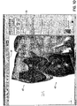
- a user may see both the assemblies (maxillary 40 and mandibular 42 ⁇ in front view along with a smile arc 52.
- the smile arc 52 is a symmetric curve interpolated through BC points of maxillary incisors, drawn starting from left cuspid up to right cuspid. Two points on the cuspids 56 are the fixed whereas two intermediate points 54 are flexible and can be moved.
- user selects one of the movable control points 54 and drags the control point up/down, modifying the smile arc 52, upper incisors will move up/down with the curve. In/out correction is applied to avoid interference with lower assembly.
- Anchor points 56 of the smile arc 52 are displayed in a different color.
- the software package contains a feature that allows the user to adjust the front four teeth along an arc type path.
- the adjustment arc is permanently attached to the top left and right cuspids.
- the adjustment arc known as the smile arc 52 in the software also contains several control points 54 located between the anchor points 56. These control points 54 allow the user to adjust the smile arc 52 by moving the control points 54 in a vertical direction. As the control points 54 are moved the front four upper teeth move as well following the adjustments to the smile arc 52.
- the user would select the Smile Arc icon 50 from the tool bar or from the menu system by selecting Edit and then Smile Arc.
- the user selects the moveable control point 54 on the smile arc 52 with his mouse and while holding down the left mouse button, drags the control point 54, which in turn moves the corresponding teeth, to the new desired location. At that point the user releases the mouse button and the teeth are set in their new location. If further adjustments are necessary, the user would follow the same procedure of selecting one of the control points 54 and then holding down the left mouse button, make the adjustment. Predetermined limits set bounds for the adjustments to the front four teeth.
- the display area will become single window. Transparent teeth will be visible along with the mantrough curve.
- the user can select one of the control points available along the mantrough (a representation of the patient's mandibular trough) and drag it. On dragging the control point, shape of mantrough curve will be modified accordingly and mandibular 42 as well as maxillary 40 teeth will be modified to reflect those changes.
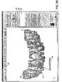
- Edit Mantrough shows the distances between BC lines 64. Every BC line will 64 show distance values such as 31.9 (1.3). In this example 31.9 is a BC distance on setup and the value inside the brackets is a deviation from that initial value.
- the Edit Mantrough feature of the software allows the user to change the shape of the mantrough.
- the method of calculating an orthodontic setup of a patient's teeth includes calculating a symmetrical arch comprising fixing points 66 along the lower incisors to align the lower incisal edges to a best-fit buccal cusp curve that enables placement of upper incisors. This curve is calculated from points at the measured distances on midline to define thereby the origin of an anterior bezier handle, and defining the mesial facial cusps of lower molars as posterior bezier handles.
- the method of using bezier handles is described in U. S. Patent Nos. 6,015,289 , 6,244,861 , and 6,616,444 , which are expressly incorporated herein in their entirety by reference.
- the user may select the Edit Mantrough icon 60 from the tool bar or from the menu system by selecting Edit and then Edit Mantrough.
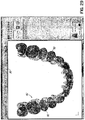
- the teeth 40, 42 and the curve 62 are displayed along with a plurality of tooth-to-tooth distance measurements.
- the curve 62 is anchored to the two rear most teeth and series of bezier handles, referred to in the software as Control Points 67, 68 or sometimes curvature knots, are available to the user to make adjustments to the curve 62.
- the user selects one of the control points 67, 68 with his mouse and while holding down the left mouse button, drags the control point 67, 68 to the new location, thus changing the shape of the curve62.
- the teeth 40, 42 automatically follow the curve 62 in real time allowing the user to graphically see how the changes in the shape of the curve 62 affect the placement of the teeth40, 42.
- the control points 67, 68 may be moved in horizontal and/or vertical directions. Preset limits bound the distance that a control point 67, 68 may be moved. As the control points 67, 68 are moved, the updated tooth to tooth lines 64 and distance measurements are displayed along with a the distance that the two teeth have moved relative to their the original position. The original curve 62' is also continuously displayed in an alternate color allowing the user to see the deviations made from the original position asn the control points 67, 68 are moved. Control point movement may be set so that corresponding control points 67, 68 follow the same but mirror image of their counterpart being moved in order to make symmetrical adjustments. Alternatively, the control points 67, 68 may be independent of one another for unsymmetrical adjustments.
- the clipping plane functionality provides a sectioned view of a tooth.
- a plane (clipping plane 72) is used to section the tooth. The user may toggle between:
- the clipping plane 72 may provide the user with an interactive cross sectioning of the teeth.
- the clipping plane operates 72 in two modes as shown above. In the first mode the teeth 40, 42 stay stationary and the clipping plane 72 moves normal to the mantrough curve. In the second mode, the clipping plane 72 is positioned parallel to the screen and remains stationary as the teeth 40, 42 are rotated through the plane.
- the user selects the Clipping Interaction icon 70 from the tool bar or selects from the menu, View and Clipping Interaction.
- the user has the option to display a representation of the clipping plane 72 in either mode. If the user has selected to view the plane 72, a transparent, outline representation of the plane 72 is dynamically displayed on the screen as the plane 72 is moved through the teeth 40, 42.
- a slide bar 79 is used to move the clipping plane 72 along the mantrough curve.
- the cut planes 74, 76 of the teeth 40, 42 are displayed in a color other than that used for the teeth 40, 42 or the root portions to allow the user to easily identify the cut section.
- the teeth 40, 42 can be oriented in any position before or during the clipping plane 72 interaction. If the position of the teeth 40, 42 obstructs the view of the cross section 74, 76, the user may select the Toggle Side button 78, which may alternate the side of the clipping plane 72 on which the teeth 40,42 are displayed, thus eliminating the obstruction.
- the alternate mode of operation for the clipping plane 72 is to make the clipping plane 72 parallel to the screen and then move the teeth 40, 42 though the plane.
- An advantage of this mode of operation of the clipping plane 72 is that the clipping plane 72 is never obstructed.
- the parallel orientation of the clipping plane may also be useful for users in determining bite conditions and tooth overlap after the teeth 40, 42 have been adjusted.
- the user may turn on or make visible a representation of the clipping plane 72.
- Manual Override 80 by selecting Manual Override 80, a user may double click on, or otherwise select, any tooth to get a graphical display of six degrees of freedom 82 to make adjustments. Selecting one of the degrees of freedom 82 and dragging it changes the tooth orientation. When the user moves the mouse over the degrees of freedom 82, a tool-tip 84 will be shown accordingly. Double clicking on any tooth from anywhere in the software package will automatically take user to manual over-ride functionality.
- the manual override function allows for a user to individually manipulate the teeth 40,42.
- a user may select the Manual Override icon 80 from the tool bar, or from the menu system, select Edit and then Manual Override.
- the user may also simply double click on a tooth to enter the Manual Override mode from any view for that particular tooth.
- a graphical representation of the six degrees of freedom 82 of movement for the tooth is displayed. The three translational degrees of freedom, Occlusal-Gingival 102, In-Out 104, and Mesio-Distal 106 move the tooth along straight lines.
- Rotation 103 rotates the tooth around the translational axes. Movement of the tooth in any of these directions is accomplished by selecting the appropriate degree of freedom with the mouse, then while holding down the left mouse button, manipulating the tooth.
- An advantage of having this functionality available at any time by double clicking on a tooth helps to streamline the process for the user and may eliminate additional steps of having to leave a particular function to get to the Manual Override function to then have to return to the previous function.
- the graphical representation of the six degrees of freedom 82 may be manipulated by the check boxes 86 on the manual override menu. Only those degrees of freedom checked will be displayed as can be seen in the representation of the degrees of freedom 82' in FIG. 17 .
- the manual override may be applied to two teeth simultaneously by selecting the "Apply Symmetric Change" 88 feature on the menu. When selected any manipulations to a tooth will automatically be applied to a corresponding tooth resulting in symmetric movements of the two teeth.
- a graphical representation of the six degrees of freedom 82 of the tooth movement is displayed on the chosen tooth.
- Each of these degrees of freedom is represented by a graphical arrow 102-107, which may be selected by the user.
- a Tool-tip 84 containing the description of that degree of freedom and a numerical value of the relative movement for that degree of freedom is displayed. Holding down the left mouse key allows the user to drag the arrow in the direction of the mouse movement. This in turn moves the tooth. As the arrow and the tooth are being moved, the numerical value of the relative movement for the degree of freedom is being updated in real time.
- Predetermined limits bound the movements for each of the degrees of freedom. When the limit for the movement is reached, the movement stops and the user is warned that the operation would exceed the maximum allowed limit.
- the six degrees of freedom that can be adjusted are the three translational degrees of freedom, Occlusal-Gingival 102, In-Out 104, and Mesio-Distal 106, and the three rotational degrees of freedom, Rotation 103, Tip 105, and Torque 107.
- the user may add graphically linked notes to individual teeth.
- the user may select the Posted Notes icon 90 from the tool bar or from the menus, Edit and then Posted Notes.
- the user may Add New Note 91, which will prompt the user for a note caption, a summary, in which the user may include any type of textual information that he/she would like to be associated with the tooth.
- the user selects an anchor location on a tooth and drags a lead line off the tooth to create a text box 94, 96.
- the user may then type text in the text box 94, 96.
- the text box 92 After the note has been entered in the text box 94, 95, the text will be added to the list of notes 92.
- the user may either select the note based on its caption94', 96' from the list of notes available.
- the "H" Button 46 in the main toolbar will toggle the color of teeth 40, 42 based on whether they have changed position relative to their original setup. Movements of teeth when viewed in one orientation may not be readily apparent to users when the teeth are being displayed in an alternate orientation. This can be particularly true if the movements to the teeth are very slight.
- the H tool will highlight 48 any tooth that has been moved since the last saved position.
- the user may select the Toggle Changed Tooth Highlighting icon 46 from the tool bar or from the menus select View and then Toggle Changed Tooth Highlighting. Selecting this option the first time will toggle the feature to be on.
- any tooth that is not in its original position from the last saved configuration is colored differently 48 from the other teeth 40, 42 that have not moved.
- the user may disable the tooth highlighting by again selecting the Toggle Changes Tooth Highlighting icon 46 from the tool, bar or from the menus selecting View and then Toggle Changed Tooth Highlighting which toggles the highlighting feature to be off.
- the color of a tooth will automatically change any time a tooth is moved when the highlighting feature is toggled on. There is no need to toggle the highlighting between on and off to update the colors on the teeth that have moved.
- the Occlusogram tool is used as a pictorial representation of the amount of interference 112 between the tooth mass of the mandibular 42 and maxillary 40 assemblies.
- the tool can be accessed by selecting the Occlusogram icon 110 from the tool bar or from the menu system by selecting View and then Occlusogram.
- the pictorial representation shows different levels of intersection between the teeth. This tool may be used to replace or augment the current manual practice of using carbon paper to check tooth alignment. This tool, used in conjunction with the clipping plane tool may be helpful to the user of the software in determining and correcting tooth alignment when teeth incorrectly overlap or intersect, ultimately affecting the bite.
- the overlay function may be selected using the overlay icon 120 or from the menus by selecting View and then overlay assemblies. This option may be used to show the original assemblies 40', 42' and assemblies after treatment 40, 42 overlaying each other for visual comparison.
- FIGS 31 and 32 Another method for comparing may be seen in FIGS 31 and 32 .
- the side by side comparison may be activated when a user selects the Compare Setup icon 130.
- the view area is divided in half and the user may then select what is to be shown in each half.
- Model data may be selected from the view menus 132, 134.
- one of the views may show real patient pictures for comparison by making a selection form the menu 136 as best seen in FIG. 32 .
- undo 140 and redo 142 buttons become active.
- the user can undo/redo multiple edits with one mouse pick.
- the user has access to a sequential undo function.
- the software is capable of undoing all actions in the reverse order of their creation up to the last point at which the configuration was saved.
- the user may access the Undo function through the menus by choosing Edit and then Undo.
- the user may also access the Undo function by selecting the Undo icon 140 on the tool bar.
- An advantage for the user in using the icon on the tool bar is that the icon 140 also has a pull down menu 144 that allows the user to access a list of all of the users actions since the last save. If the user selects one of the actions in the middle of the list, the software will undo all of the actions up to and including that action. This functionality assists a user in undoing a group of actions that may have lead to an unsatisfactory result.
- the user also has access to a sequential redo function that works like the undo function in reverse.
- the Redo function may also be accessed through the menu system by selecting Edit and then Redo.
- the user may also access the Redo icon 142 on the tool bar.
- the Redo icon 142 may also contain a pull down menu (not shown) listing all of the commands that were executed. If the user uses the pull down menu 144 to undo a plurality of commands from the undo pull down menu 144 and then realizes that he/she went too far by mistake, the user may use the Redo icon 142 and pull down menu to reconstruct the commands that were inadvertently undone.
- the ability to undo and redo commands coupled with the ability to pick from a list of executed commands and have the software either undo back to that point or redo up to that point provides power and flexibility to the user when manipulating objects on the display.
- the user may create animation sequences of the teeth 40, 42 moving from an original position to a new adj usted position so that the patients may see the effects of the adjusted teeth.
- the user may save this animation sequence in a computer compatible movie file that the user may then send home with the patient.
- This feature may be used as a marketing tool for an office that uses the software program as that it could be viewed as an added service provided by the office for its patients.
- the software may be configured with a viewing toolbar 160, which assists a user in quickly changing from one orientation or view to another.
- the maxillary teeth 40 may be displayed or removed by toggling the maxillary icon 162.
- the mandibular teeth 42 may be displayed or removed by toggling the mandibular icon 164.
- An icon 166 for the brackets 67 may be toggled to display the brackets 167 on the teeth 42 as best seen in FIG. 35 .
- an icon 168 for the archwire 169 may be toggled to display the archwire on the teeth 42 as also seen in FIG. 35 .
- Preferences for the treatment of a patient associated with the brackets and archwires, as well as any other applicable appliance may be set up in the menus for treatment preferences 170 as seen in FIGS. 36A and 36B .
- the menu has expandable categories, which may be adjusted prior to delivery of the software package or in other embodiments, directly be the user. These preferences will then be the preferences for designing for a particular case and in some embodiments may not be overwritten by a Doctor's default preferences.
Landscapes
- Health & Medical Sciences (AREA)
- Engineering & Computer Science (AREA)
- Public Health (AREA)
- Biomedical Technology (AREA)
- Medical Informatics (AREA)
- General Health & Medical Sciences (AREA)
- Epidemiology (AREA)
- Primary Health Care (AREA)
- Business, Economics & Management (AREA)
- General Business, Economics & Management (AREA)
- Pathology (AREA)
- Databases & Information Systems (AREA)
- Data Mining & Analysis (AREA)
- Oral & Maxillofacial Surgery (AREA)
- General Engineering & Computer Science (AREA)
- Dentistry (AREA)
- Life Sciences & Earth Sciences (AREA)
- Animal Behavior & Ethology (AREA)
- Veterinary Medicine (AREA)
- Dental Tools And Instruments Or Auxiliary Dental Instruments (AREA)
- Image Generation (AREA)
Description
- This application claims the benefit of the
U.S. Provisional Application Serial No. 60/777,483, filed 28 February 2006 - The invention relates generally to the field of orthodontics and, more particularly, to computer-automated development of an orthodontic treatment plan and appliance.
- The orthodontic treatment of patients has as its fundamental objective the repositioning or realignment of the teeth of a patient in the patient's mouth to positions where they function optimally together and occupy relative locations and orientations that define a pair of opposed and cooperating planar, or nearly planar, smooth arches. The teeth of the two arches, the maxillary arch of the teeth of the upper jaw and the mandibular arch of the teeth of the lower jaw, when in optimal or ideal positions, contact the teeth of the opposite arch along a surface that is usually flat or slightly upwardly concave and commonly referred to as the plane of occlusion.
- The treatment applied to patients who have been diagnosed as having teeth insufficiently close to the ideal positions to require orthodontic correction includes an initial or rough procedure to overcome the more serious defects of tooth positioning followed by a finish treatment designed to bring the teeth as closely as possible or practical to their ideal positions. The rough treatment usually involves the movement of certain teeth through the use of any of a number of recognized techniques performed by an orthodontist, and sometimes procedures such as the extraction of certain teeth or surgery on the patient's jaw performed by an oral surgeon.
- In the finish treatment, the orthodontist applies an appliance to the teeth of the patient to exert continual forces on the teeth of the patient to gradually urge them toward their ideal positions. The most common, but not the only, type of appliance is a set of braces made up of brackets and arch wires. The application of this type of appliance usually involves the attachment of brackets to the teeth, either with the application of adhesive to the teeth or the securing of bands around the teeth. The brackets are usually each provided with a slot through which an arch wire is extended. One arch wire is provided for the upper teeth and one for the lower teeth. Typically, the slots in the brackets are of rectangular cross-section and the arch wire is of rectangular cross-section. The arch wire installed in the slots of the brackets interconnects the teeth, through the brackets, and exerts forces on the teeth to translate or rotate them toward a finish position envisioned by the orthodontist.
- In dental procedures in general and more specifically in orthodontic procedures, a model of a patient's teeth is required in order to make treatment decisions in, for example, design of braces, crowns, bridges, etc., and to allow monitoring of dental procedures. Of particular importance is knowledge of the distance and spatial relationship between the teeth on opposite jaws.
- Dental procedures requiring knowledge of the position of teeth and the distance between teeth on opposite jaws, generally use models of the teeth, referred to hereinafter as "dental models". Typically, plaster dental models are used, which are made by casting plaster into the negative impression made by teeth in an appropriate matrix. Dental models can, however, be made of any convenient material.
- This approach, however, has a number of major drawbacks. First, in the occluded state it is difficult to see the relation between facing surfaces of opposite teeth of the upper and lower jaws. Second, on moving a tooth, or adding a tooth, or changing the form of a tooth in the dental model, it is not easy to see if the affected tooth affects the occlusion. Third, the information provided by dental models regarding proximity of opposite teeth in opposite jaws is typically no more than whether certain points of opposite teeth make contact, or not, in the occluded state. In order to be able to arrive at an optimal closing of the teeth when changes are made to one or more of the teeth of the dental model, a fairly long and tiresome process of physically modeling the affected teeth is required in order to ensure a good fit between opposite teeth on opposite jaws in the occluded state.
- It has been recognized in the design and application of orthodontic appliances that an ideally designed and installed orthodontic appliance will, for example, present the slots of the brackets in a position to initially receive a pre-shaped arch wire that will elastically deform to exert corrective forces on the teeth to urge them toward their finish positions. When in their finish positions, the arch wire of the ideally designed appliance will no longer be elastically deformed, and will no longer exert forces upon the teeth. Achieving this objective has been inhibited by certain problems in the prior art.
- One problem presented by the prior art is that current orthodontic products are designed and manufactured to average anatomy. As a result, orthodontists are faced with the need to select what they perceive to be the brackets and arch wires of the closest design to those required by a particular patient, and to modify the designs for treatment of the patient. Some of this modification may be performed when the appliance is initially installed, but almost inevitably modification is required during the course of treatment of the patient. This modification may take the form of the replacement of brackets, but most commonly requires a periodic bending and reshaping of the arch wire as the treatment progresses. Thus, the treatment of the patient has become a manual feedback system in which the orthodontist monitors the progress of the patient's treatment and then readjusts the appliance, usually by bending the arch wires, to correct the forces being applied to the teeth to bring the teeth to their ultimate positions, which are less than ideal. As a result, the patient may be subjected to treatment over a period that is longer than would be necessary if the appliance were initially made to the optimum design. In addition, the time required of the orthodontist for implementation of the treatment may be several times greater than it would be if modification of the appliance were unnecessary. Thus, the orthodontist is able to treat fewer patients and the cost of the treatment to the patient or to the orthodontist is increased.
- Location of the connection points for the appliance to the teeth also presents a problem in the prior art. Typically, brackets are bonded to the teeth and then interconnected by the installation of the arch wires. This is done when the teeth are in their maloccluded positions, with the orthodontist having only a mental vision of where the finish positions of the teeth will be and where the brackets are to be placed to move the teeth to those finish positions. For more effective use of the appliance and to promote ease in cleaning the teeth, the orthodontist prefers to locate the brackets and arch wires away from the gums. If they are placed to close to the tips of the teeth, however, they may interfere with the teeth of the opposite arch as the teeth approach their finish positions.
- Another problem of the prior art that has inhibited the selection or design of an ideal orthodontic appliance for the patient is the difficulty in arriving at an expression of the ideal finish position of the teeth. Orthodontists typically make models of the patient's mouth and, with the models and the aid of x-rays, determine a treatment to move the teeth to finish tooth positions. This process is time consuming and presents a source of error and inaccuracy. From the measurements and based on the judgment of the orthodontist, appliance components are selected to implement the prescribed treatment. In reality, the treatment of patients is in many cases more of an art than a science, with results ranging from poor to excellent, and generally variable.
- The need for custom manufactured orthodontic appliances and the use of automatic design techniques has been recognized by some, while others have advocated adherence to standard components and manual techniques in view of a perceived lack of practical custom appliance manufacturing and automated appliance design systems of the art.
- The development of automated custom appliance design systems has encountered several difficulties. These difficulties have included the task of developing an automated system that includes reliable and efficient decision making algorithms and techniques for automatically determining an ideal finish position of the teeth. Further, these difficulties have included arriving at an expression of appliance geometry in terms that can be efficiently produced by automated appliance manufacturing equipment. Furthermore, the prior art has not provided a way to accurately manufacture an appliance on an individualized basis in accordance with the appliance design. An additional problem in the automated design and manufacture of orthodontic appliances lies in the difficulty in designing the custom design system to take into account the professionally recognized parameters and criteria, derived over many years from the knowledge and experience of the practicing and clinical orthodontist, upon which diagnosis and treatment is based.
- Tooth positioners for finishing orthodontic treatment are described by Kesling in the Am. J. Orthod. Oral. Surg. 31:297-304 (1945) and 32:285-293 (1946). The use of silicone positioners for the comprehensive orthodontic realignment of a patient's teeth is described in Warunek et al. (1989) J. Clin. Orthod. 23:694-700. Clear plastic retainers for finishing and maintaining tooth positions are commercially available from Raintree Essix, Inc., New Orleans, La. 70125, and Tru-Tain Plastics, Rochester, Minn. 55902. The manufacture of orthodontic positioners is described in
U.S. Pat. Nos. 5,186,623 ;5,059,118 ;5,055,039 ;5,035,613 ;4,856,991 ;4,798,534 ; and4,755,139 . - Other publications describing the fabrication and use of dental positioners include Kleemann and Janssen (1996) J Clin. Orthodon. 30:673-680; Cureton (1996) J Clin. Orthodon. 30:390-395; Chiappone (1980) J Clin. Orthodon. 14:121-133; Shilliday (1971) Am. J. Orthodontics 59:596-599; Wells (1970) Am. J. Orthodontics 58:351-366; and Cottingham (1969) Am. J. Orthodontics 55:23-31.
- Kuroda et al. (1996) Am. J. Orthodontics 110:365-369 describes a method for laser scanning a plaster dental cast to produce a digital image of the cast. See also
U.S. Pat. No. 5,605,459 . -
-
U.S. Pat. No. 5,011,405 describes a method for digitally imaging a tooth and determining optimum bracket positioning for orthodontic treatment. Laser scanning of a molded tooth to produce a three-dimensional model is described inU.S. Pat. No. 5,338,198 .U.S. Pat. No. 5,452,219 describes a method for laser scanning a tooth model and milling a tooth mold. Digital computer manipulation of tooth contours is described inU.S. Pat. Nos. 5,607,305 and5,587,912 . Computerized digital imaging of the jaw is described inU.S. Pat. Nos. 5,342,202 and5,340,309 . Other patents of interest includeU.S. Pat. Nos. 5,549,476 ;5,382,164 ;5,273,429 ;4,936,862 ;3,860,803 ;3,660,900 ;5,645,421 ;5,055,039 ;4,798,534 ;4,856,991 ;5,035,613 ;5,059,118 ;5,186,623 ; and4,755,139 . - With the advent of powerful computers and advanced computer aided design techniques, three-dimensional virtual dental models help in alleviating the problems encountered with the plaster dental models. Storing a computer virtual dental model on a computer can be achieved "directly" by scanning and digitizing the teeth and gums, or "indirectly" by utilizing a plaster dental model or the negative impression. The latter method is disclosed in PCT Application No.
PCT/ IL 96/00036WO 97/03622, published on Feb. 6, 1997 -
US 2004/0073417 discloses an interactive, software-based treatment planning method to correct a malocclusion. The method can be performed on an orthodontic workstation in a clinic or at a remote location such as a lab or precision appliance manufacturing center. The workstation stores a virtual three-dimensional model of the dentition of a patient and patient records. The virtual model is manipulated by the user to define a target situation for the patient, including a target archform and individual tooth positions in the archform. - The invention is define by the claims.
- Disclosed herein is a software modeling tool capable of manipulating the digital images of the teeth from their original position as digitized and scanned to an optimal position. The tool allows the treating orthodontist to develop a treatment plan based on evaluating tooth movements in the modeling tool.
- The software modeling tool assists the orthodontist in manipulating he tooth positions by allowing to orthodontist to adjust the following items. The orthodontist may adjust the positions of the smile teeth, the front four teeth that are most visible when a person smiles by adjusting the teeth along an arc. The orthodontist may adjust the spacing of the teeth in the mandible and their relative positions corresponding to a curve fit through the mandible for optimal ooth placement. The orthodontist may utilize tools that cross section the teeth which allows him/her to check for alignment interferences between the top and bottom teeth. The orthodontist may adjust an individual tooth in six different degrees of freedom to place the tooth in its optimal position or in a position for better movement with other teeth. The orthodontist also has the ability to review a simulated representation of the occlusal points with the teeth in their current and new positions to assist in developing the treatment plan.
- The software modeling tool may also assist the orthodontist by allowing him to add notations to teeth as part of the treatment process. The software modeling tool may indicate to the orthodontist, which teeth have moved from their original position. It allows the orthodontist to undo and redo tooth movements as the orthodontist is developing the treatment plan. The software modeling tool allows the orthodontist to create animation sequences of the teeth moving from their original portions to their final positions and save those
animations to appropriate files, which may be archived or even given to patients as a marketing tool, by the office to show them the effects of the treatment. - From the foregoing disclosure and the following more detailed description of various preferred embodiments it will be apparent to those skilled in the art that the present invention provides a significant advance in the technology of developing treatment plans for orthodontics. Particularly significant in this regard is the potential the inventor affords for providing the orthodontist to simulate tooth movements and check for proper alignments before a treatment plan is started. Additional features and advantages of various preferred embodiments will be better understood in view of the detailed description provided below.
- These and further features of the present invention will be apparent with reference to the following description and drawings wherein:
-
FIG. 1 contains a representative screen shot from the software showing the adjustment of the smile arc; -
FIG. 2 contains a representative screen shot from the software showing the smile arc adjusted downward; -
FIG. 3 contains a representative screen shot from the software showing the smile arc adjusted upward; -
FIG. 4 contains a representative screen shot from the software showing the adjustment of the mantrough; -
FIG. 5 contains a representative screen shot from the software showing the mantrough adjusted outward; -
FIG. 6 contains a representative screen shot from the software showing the mantrough adjusted inward; -
FIG. 7 contains a representative screen shot from the software showing the use of a clipping plane where the plane moves through the teeth; -
FIG. 8 contains another representative screen shot from the software showing the use of a clipping plane where the plane moves through the teeth; -
FIG. 9 contains a representative screen shot from the software showing the use of a clipping plane where the plane remains stationary and the teeth move through the plane; -
FIG. 10 contains another representative screen shot from the software showing the use of a clipping plane where the plane remains stationary and the teeth move through the plane; -
FIG. 11 contains another representative screen shot from the software showing the use of a clipping plane where the plane remains stationary and the teeth move through the plane; -
FIG. 12 contains another representative screen shot from the software showing the use of a clipping plane where the plane remains stationary and the teeth move through the plane; -
FIG. 13 contains another representative screen shot from the software showing the use of a clipping plane where the plane remains stationary and the teeth move through the plane; -
FIG. 14 contains a representative screen shot from the software showing the manual override of a position of a tooth; -
FIG. 15 contains a representative screen shot from the software showing the tooth being adjusted up and down; -
FIG. 16 contains a representative screen shot from the software showing the tooth being adjusted by twisting front to back; -
FIG. 17 contains a representative screen shot from the software showing the tooth being adjusted by moving left to right; -
FIG. 18 contains a close up screen shot from the software showing the Occlusal-Gingival translational degree of freedom of movement; -
FIG. 19 contains a close up screen shot from the software showing the In-Out translational degree of freedom of movement; -
FIG. 20 contains a close up screen shot from the software showing the translational Mesio-Distal degree of freedom of movement; -
FIG. 21 contains a close up screen shot from the software showing the Rotation rotational degree of freedom of movement; -
FIG. 22 contains a close up screen shot from the software showing the Tip rotational degree of freedom of movement; -
FIG. 23 contains a close up screen shot from the software showing the Torque rotational degree of freedom of movement; -
FIG. 24 contains a representative screen shot from the software showing a tooth being marked with an associated note; -
FIG. 25 contains a representative screen shot from the software showing an alternate tooth being marked with an associated note; -
FIG. 26 contains a representative screen shot from the software showing the corresponding note on the tooth when the note is selected form the menu on the right; -
FIG. 27 contains a representative screen shot from the software showing the highlighting of teeth that have been moved from their original position; -
FIG. 28 contains another representative screen shot from the software showing the highlighting of teeth that have been moved from their original position; -
FIG. 29 contains a representative screen shot from the software showing the simulation of occlusal points; -
FIG. 30 contains a representative screen shot from the software showing the maloccluded model overlaying the current model; -
FIG. 31 contains a representative screen shot from the software showing the ability to compare models side by side; -
FIG. 32 contains a representative screen shot from the software showing a comparison between a patient's actual teeth and a computer model. -
FIG. 33 contains a representative screen shot from the software showing the multilevel undo function; -
FIG. 34 contains a representative screen shot from the software showing the ability to save animation sequences; -
FIG. 35 contains a representative screen shot from the software showing the teeth in the mandible containing brackets and an archwire; -
FIG. 36A contains a representative screen shot of a portion of the software showing a menu for treatment preferences; and -
FIG. 36B contains a representative screen shot of the portion of the software shown inFIG. 36A with some treatment preference menus expanded. - Systems and methods that use computers to model a patient's teeth and to design orthodontic treatment and appliances have been proposed by applicant, examples of which are disclosed in International Applications Nos.
PCT/US2003/030917, filed on September 26, 2003 , and International Patent Application No.PCT/USOO/35558. filed December 29, 2000 . Typical systems of these types provide an interface through which a treating orthodontist or others can communicate treatment and design preferences and data. - Traversing the functionality of the software containing the computer implemented method, and referring now to
FIGS. 1 through 3 , upon picking aSmile Arc icon 50, a user may see both the assemblies (maxillary 40 and mandibular 42} in front view along with asmile arc 52. Thesmile arc 52 is a symmetric curve interpolated through BC points of maxillary incisors, drawn starting from left cuspid up to right cuspid. Two points on thecuspids 56 are the fixed whereas twointermediate points 54 are flexible and can be moved. When user selects one of the movable control points 54 and drags the control point up/down, modifying thesmile arc 52, upper incisors will move up/down with the curve. In/out correction is applied to avoid interference with lower assembly. Anchor points 56 of thesmile arc 52 are displayed in a different color. - Only some of the teeth in a person's mouth are visible in a smile. These teeth, referred to as the "smile teeth" primarily consist of the front four upper teeth. Being able to adjust these four teeth along a smooth arc may give the impression of a much better smile without the need to adjust all of the teeth. In order to determine the adjustments to the smile teeth, the software package contains a feature that allows the user to adjust the front four teeth along an arc type path. The adjustment arc is permanently attached to the top left and right cuspids. The adjustment arc, known as the
smile arc 52 in the software also containsseveral control points 54 located between the anchor points 56. These control points 54 allow the user to adjust thesmile arc 52 by moving the control points 54 in a vertical direction. As the control points 54 are moved the front four upper teeth move as well following the adjustments to thesmile arc 52. - Initially the user would select the
Smile Arc icon 50 from the tool bar or from the menu system by selecting Edit and then Smile Arc. To move acontrol point 54, the user selects themoveable control point 54 on thesmile arc 52 with his mouse and while holding down the left mouse button, drags thecontrol point 54, which in turn moves the corresponding teeth, to the new desired location. At that point the user releases the mouse button and the teeth are set in their new location. If further adjustments are necessary, the user would follow the same procedure of selecting one of the control points 54 and then holding down the left mouse button, make the adjustment. Predetermined limits set bounds for the adjustments to the front four teeth. - Referring now to
FIGS. 4 through 6 , by selecting Edit Mantrough, the display area will become single window. Transparent teeth will be visible along with the mantrough curve. The user can select one of the control points available along the mantrough (a representation of the patient's mandibular trough) and drag it. On dragging the control point, shape of mantrough curve will be modified accordingly and mandibular 42 as well as maxillary 40 teeth will be modified to reflect those changes. - Edit Mantrough shows the distances between BC lines 64. Every BC line will 64 show distance values such as 31.9 (1.3). In this example 31.9 is a BC distance on setup and the value inside the brackets is a deviation from that initial value.
- The Edit Mantrough feature of the software allows the user to change the shape of the mantrough. The method of calculating an orthodontic setup of a patient's teeth includes calculating a symmetrical arch comprising fixing points 66 along the lower incisors to align the lower incisal edges to a best-fit buccal cusp curve that enables placement of upper incisors. This curve is calculated from points at the measured distances on midline to define thereby the origin of an anterior bezier handle, and defining the mesial facial cusps of lower molars as posterior bezier handles. The method of using bezier handles is described in
U. S. Patent Nos. 6,015,289 ,6,244,861 , and6,616,444 , which are expressly incorporated herein in their entirety by reference. - To change the shape of the mantrough, the user may select the
Edit Mantrough icon 60 from the tool bar or from the menu system by selecting Edit and then Edit Mantrough. Theteeth curve 62 are displayed along with a plurality of tooth-to-tooth distance measurements. Thecurve 62 is anchored to the two rear most teeth and series of bezier handles, referred to in the software asControl Points 67, 68 or sometimes curvature knots, are available to the user to make adjustments to thecurve 62. To adjust thecurve 62, the user selects one of the control points 67, 68 with his mouse and while holding down the left mouse button, drags thecontrol point 67, 68 to the new location, thus changing the shape of the curve62. As thecurve 62 changes shape, theteeth curve 62 in real time allowing the user to graphically see how the changes in the shape of thecurve 62 affect the placement of the teeth40, 42. - The control points 67, 68 may be moved in horizontal and/or vertical directions. Preset limits bound the distance that a
control point 67, 68 may be moved. As the control points 67, 68 are moved, the updated tooth totooth lines 64 and distance measurements are displayed along with a the distance that the two teeth have moved relative to their the original position. The original curve 62' is also continuously displayed in an alternate color allowing the user to see the deviations made from the original position asn the control points 67, 68 are moved. Control point movement may be set so that corresponding control points 67, 68 follow the same but mirror image of their counterpart being moved in order to make symmetrical adjustments. Alternatively, the control points 67, 68 may be independent of one another for unsymmetrical adjustments. - Referring now to
FIGS. 7 and8 , the clipping plane functionality provides a sectioned view of a tooth. A plane (clipping plane 72) is used to section the tooth. The user may toggle between: - Method 1: The clipping
plane 72 will be parallel to the screen & as the user moves theplane 72 by using slider bar/dragging the mouse, theassembly - Method 2: View that was currently active, where the clipping
plane 72 moves relative to theassembly - Clicking the "Toggle Side"
Button 78 will alternate showing theassembly plane 72. - The clipping
plane 72 may provide the user with an interactive cross sectioning of the teeth. The clipping plane operates 72 in two modes as shown above. In the first mode theteeth plane 72 moves normal to the mantrough curve. In the second mode, the clippingplane 72 is positioned parallel to the screen and remains stationary as theteeth plane 72, the user selects theClipping Interaction icon 70 from the tool bar or selects from the menu, View and Clipping Interaction. The user has the option to display a representation of the clippingplane 72 in either mode. If the user has selected to view theplane 72, a transparent, outline representation of theplane 72 is dynamically displayed on the screen as theplane 72 is moved through theteeth slide bar 79 is used to move the clippingplane 72 along the mantrough curve. The cut planes 74, 76 of theteeth teeth - In the first mode the
teeth plane 72 interaction. If the position of theteeth cross section Toggle Side button 78, which may alternate the side of the clippingplane 72 on which theteeth - Referring now to
FIGS. 9 through 13 , the alternate mode of operation for the clippingplane 72 is to make the clippingplane 72 parallel to the screen and then move theteeth plane 72 is that the clippingplane 72 is never obstructed. The parallel orientation of the clipping plane may also be useful for users in determining bite conditions and tooth overlap after theteeth plane 72. - Referring now to
FIGS. 14 through 23 , by selectingManual Override 80, a user may double click on, or otherwise select, any tooth to get a graphical display of six degrees offreedom 82 to make adjustments. Selecting one of the degrees offreedom 82 and dragging it changes the tooth orientation. When the user moves the mouse over the degrees offreedom 82, a tool-tip 84 will be shown accordingly. Double clicking on any tooth from anywhere in the software package will automatically take user to manual over-ride functionality. - The manual override function allows for a user to individually manipulate the
teeth Manual Override icon 80 from the tool bar, or from the menu system, select Edit and then Manual Override. The user may also simply double click on a tooth to enter the Manual Override mode from any view for that particular tooth. When a tooth has been selected for the Manual Override, a graphical representation of the six degrees offreedom 82 of movement for the tooth is displayed. The three translational degrees of freedom, Occlusal-Gingival 102, In-Out 104, and Mesio-Distal 106 move the tooth along straight lines. The three rotational degrees of freedom,Rotation 103,Tip 105, andTorque 107 rotate the tooth around the translational axes. Movement of the tooth in any of these directions is accomplished by selecting the appropriate degree of freedom with the mouse, then while holding down the left mouse button, manipulating the tooth. An advantage of having this functionality available at any time by double clicking on a tooth helps to streamline the process for the user and may eliminate additional steps of having to leave a particular function to get to the Manual Override function to then have to return to the previous function. - The graphical representation of the six degrees of
freedom 82 may be manipulated by thecheck boxes 86 on the manual override menu. Only those degrees of freedom checked will be displayed as can be seen in the representation of the degrees of freedom 82' inFIG. 17 . The manual override may be applied to two teeth simultaneously by selecting the "Apply Symmetric Change" 88 feature on the menu. When selected any manipulations to a tooth will automatically be applied to a corresponding tooth resulting in symmetric movements of the two teeth. - Referring specifically now to
FIGS. 18 through 23 , when the Manual Override functionality is activated, a graphical representation of the six degrees offreedom 82 of the tooth movement is displayed on the chosen tooth. Each of these degrees of freedom is represented by a graphical arrow 102-107, which may be selected by the user. When a degree of freedom is selected with the mouse, a Tool-tip 84 containing the description of that degree of freedom and a numerical value of the relative movement for that degree of freedom is displayed. Holding down the left mouse key allows the user to drag the arrow in the direction of the mouse movement. This in turn moves the tooth. As the arrow and the tooth are being moved, the numerical value of the relative movement for the degree of freedom is being updated in real time. Predetermined limits bound the movements for each of the degrees of freedom. When the limit for the movement is reached, the movement stops and the user is warned that the operation would exceed the maximum allowed limit. The six degrees of freedom that can be adjusted, as mentioned above and seen in theFIGS. 18 through 23 , are the three translational degrees of freedom, Occlusal-Gingival 102, In-Out 104, and Mesio-Distal 106, and the three rotational degrees of freedom,Rotation 103,Tip 105, andTorque 107. - Referring now to
FIGS. 24 through 26 , the user may add graphically linked notes to individual teeth. To add or view notes, the user may select the PostedNotes icon 90 from the tool bar or from the menus, Edit and then Posted Notes. Once at the Posted Notes menu, the user may AddNew Note 91, which will prompt the user for a note caption, a summary, in which the user may include any type of textual information that he/she would like to be associated with the tooth. To add a note, the user selects an anchor location on a tooth and drags a lead line off the tooth to create atext box text box text box 94, 95, the text will be added to the list ofnotes 92. Once a number of notes have been entered, the user may either select the note based on its caption94', 96' from the list of notes available. - Referring now to
FIGS. 27 and28 , the "H"Button 46 in the main toolbar will toggle the color ofteeth Tooth Highlighting icon 46 from the tool bar or from the menus select View and then Toggle Changed Tooth Highlighting. Selecting this option the first time will toggle the feature to be on. When the highlighting feature is on, any tooth that is not in its original position from the last saved configuration is colored differently 48 from theother teeth Tooth Highlighting icon 46 from the tool, bar or from the menus selecting View and then Toggle Changed Tooth Highlighting which toggles the highlighting feature to be off. The color of a tooth will automatically change any time a tooth is moved when the highlighting feature is toggled on. There is no need to toggle the highlighting between on and off to update the colors on the teeth that have moved. - Referring now to
FIG. 29 , the Occlusogram tool is used as a pictorial representation of the amount ofinterference 112 between the tooth mass of the mandibular 42 and maxillary 40 assemblies. The tool can be accessed by selecting theOcclusogram icon 110 from the tool bar or from the menu system by selecting View and then Occlusogram. The pictorial representation shows different levels of intersection between the teeth. This tool may be used to replace or augment the current manual practice of using carbon paper to check tooth alignment. This tool, used in conjunction with the clipping plane tool may be helpful to the user of the software in determining and correcting tooth alignment when teeth incorrectly overlap or intersect, ultimately affecting the bite. - Referring not to
FIG. 30 , the overlay function may be selected using theoverlay icon 120 or from the menus by selecting View and then overlay assemblies. This option may be used to show the original assemblies 40', 42' and assemblies aftertreatment - Another method for comparing may be seen in
FIGS 31 and32 . The side by side comparison may be activated when a user selects the CompareSetup icon 130. The view area is divided in half and the user may then select what is to be shown in each half. Model data may be selected from theview menus menu 136 as best seen inFIG. 32 . - Referring now to
FIG. 33 , after the user performs any editing operation, undo 140 and redo 142 buttons become active. Using the drop downmenu 144 the user can undo/redo multiple edits with one mouse pick. - The user has access to a sequential undo function. The software is capable of undoing all actions in the reverse order of their creation up to the last point at which the configuration was saved. The user may access the Undo function through the menus by choosing Edit and then Undo. The user may also access the Undo function by selecting the Undo
icon 140 on the tool bar. An advantage for the user in using the icon on the tool bar is that theicon 140 also has a pull downmenu 144 that allows the user to access a list of all of the users actions since the last save. If the user selects one of the actions in the middle of the list, the software will undo all of the actions up to and including that action. This functionality assists a user in undoing a group of actions that may have lead to an unsatisfactory result. - In conjunction with the sequential Undo, the user also has access to a sequential redo function that works like the undo function in reverse. The Redo function may also be accessed through the menu system by selecting Edit and then Redo. The user may also access the
Redo icon 142 on the tool bar. Like the Undoicon 140, theRedo icon 142 may also contain a pull down menu (not shown) listing all of the commands that were executed. If the user uses the pull downmenu 144 to undo a plurality of commands from the undo pull downmenu 144 and then realizes that he/she went too far by mistake, the user may use theRedo icon 142 and pull down menu to reconstruct the commands that were inadvertently undone. The ability to undo and redo commands coupled with the ability to pick from a list of executed commands and have the software either undo back to that point or redo up to that point provides power and flexibility to the user when manipulating objects on the display. - Referring now to
FIG. 34 , the user may create animation sequences of theteeth - The software may be configured with a
viewing toolbar 160, which assists a user in quickly changing from one orientation or view to another. Themaxillary teeth 40 may be displayed or removed by toggling the maxillary icon 162. Similarly themandibular teeth 42 may be displayed or removed by toggling themandibular icon 164. Anicon 166 for the brackets 67 may be toggled to display thebrackets 167 on theteeth 42 as best seen inFIG. 35 . Likewise anicon 168 for thearchwire 169 may be toggled to display the archwire on theteeth 42 as also seen inFIG. 35 . - Preferences for the treatment of a patient associated with the brackets and archwires, as well as any other applicable appliance may be set up in the menus for
treatment preferences 170 as seen inFIGS. 36A and 36B . The menu has expandable categories, which may be adjusted prior to delivery of the software package or in other embodiments, directly be the user. These preferences will then be the preferences for designing for a particular case and in some embodiments may not be overwritten by a Doctor's default preferences. - While the present invention has been illustrated by a description of various embodiments and while these embodiments have been described in considerable detail, additional advantages and modifications will readily appear to those skilled in the art.
Claims (15)
- A computer-implemented method to identify an orthodontic treatment plan applicable to teeth of a human patient, the method comprising:displaying a three-dimensional perspective representation of the teeth of the patient to a user;receiving from the user a selection of an element of the orthodontic treatment plan and displaying a three-dimensional perspective representation of six degrees of freedom of movement of the selected element, each degree of freedom presented by a graphical direction of adjustment of the one or more teeth consistent with the three-dimensional perspective representation of the teeth;receiving from the user an adjustment of the selected element of the orthodontic treatment plan along a direction of movement selected from the six degrees of freedom; andmoving at least one tooth of the teeth of the patient to a new position on the display corresponding to the adjustment,wherein movement of the at least one tooth in one of the directions of adjustment is accomplished by selecting a degree of freedom with a pointing device and holding down a button of the pointing device and moving the pointing device, andwherein when the pointing device moves over a degree of freedom, a description of that degree of freedom and a numerical value of the relative movement of that degree of freedom is displayed.
- The computer-implemented method of claim 1 wherein receiving the adjustment from the user includes the user selecting one or both of a first degree and a second degree of freedom from the six degrees of freedom through user input, and the moving includes movement of the selected at least one tooth in the direction of the selected one or both degrees of freedom in response to user input of the pointing device on the selected at least one tooth
- The computer-implemented method of claim 1 or claim 2 further comprising:associating at least a portion of the teeth of the patient with a graphically displayed curve;adjusting a shape of the curve by movement of a control point of the curve in response to user input; andmoving the portion of the teeth associated with the curve to a new position based on the adjusted shape of the curve.
- The computer-implemented method of claim 3 wherein the moving of the portion of the teeth associated with the curve occurs in real time with the adjustment of the shape of the curve.
- The computer-implemented method of claim 3 or claim 4 wherein the curve is a smile arc and associating at least a portion of the teeth of the patient with the curve comprises:fixing a first end point of the smile arc to a first cuspid;fixing a second end point of the smile arc to a second cuspid; andinterpolating the arc through two additional points on a first and second maxillary incisor, wherein the smile arc spans four front teeth.
- The computer-implemented method of claim 3 or claim 4 wherein the curve is a mantrough curve and associating at least a portion of the teeth of the patient with the curve comprises:
overlaying an archform curve with a portion of the teeth of the patient in the mandible using mathematical methods. - The computer-implemented method of claim 6 further comprising either:a) displaying distances between corresponding teeth on opposites sides of the mandible; orb) displaying a change in distance from a first, original distance between the corresponding teeth on opposite sides of the mandible and a second distance between the corresponding teeth after the mantrough curve has been adjusted; orc) simultaneously displaying an original representation of the mantrough curve in addition to the adjusted mantrough curve; ord) movement of the control point causing symmetric movement of the portion of the teeth; ore) a combination of a) through d).
- The computer-implemented method of any of the above claims further comprising:retrieving an initial position of a tooth among the representation of the teeth of the patient;determining a position of the tooth subsequent to orthodontic treatment;comparing the initial position of the tooth to the subsequent position of the tooth; andin response to the subsequent position being different from the current position, highlighting the tooth.
- The computer-implemented method of claim 8 wherein either:a) the highlighting comprises changing a color of the displayed representation of the tooth; orb) the highlighting of the tooth occurs in real time as soon as it is moved from the original position; orc) both a) and b).
- The computer-implemented method of any of the above claims further comprising:
displaying a pictorial representation of an amount of interference between a tooth mass of a mandibular assembly and a maxillary assembly. - The computer-implemented method of any of the above claims further comprising:recording the movement of the one or more teeth as it is performed by a user;maintaining a sequential list of the recorded movements in the computer; andallowing the user to back up to a previous recorded movement in the sequential list of recorded movements,wherein a current movement of the control point is undone.
- The computer-implemented method of claim 11 further comprising one or more of the following:a) allowing the user to move forward though the sequential list of recorded movements to a recorded movement, wherein the undone movement is performed again; orb) providing the user with a control to select a previous recorded movement anywhere in the sequential listing, and causing all intervening recorded movements from the selected recorded movement to be undone; orc) providing the user with a control to select a previous recorded movement in the sequential listing that has been undone, causing all intervening recorded movements from the selected recorded movement to be performed again.
- The computer-implemented method of any of the above claims further comprising:
limiting the movement by predetermined bounds. - A system for identifying an orthodontic treatment plan applicable to teeth of a human patient according to the method of any of claims 1 through 13 above, the system comprising:a user interface for interfacing with a computer program;the computer program being configured to interact with a user through the user interface to display a representation of the teeth of the patient, select an element of the orthodontic treatment plan, adjust a target for the orthodontic treatment plan, and move at least one tooth of the teeth of the patient to a new position corresponding to the element adjustment according to said method, wherein if the selected element is one or more teeth, the computer program is further configured to interact with the user to display a representation of six degrees of freedom of movement on the selected one or more teeth, select a first degree of freedom from the six degrees of freedom of movement through user input, and move the one or more selected teeth in the direction of the first degree of freedom in response to user input causing movement of a pointing device on the one or more selected teeth,wherein movement of the at least one tooth in one of the directions of adjustment is accomplished by selecting a degree of freedom with the pointing device and holding down a button of the pointing device and moving the pointing device, andwherein when the pointing device moves over a degree of freedom, a description of that degree of freedom and a numerical value of the relative movement of that degree of freedom is displayed.
- The system of claim 14 wherein the computer program has one or more of the following features:a) if the target for the orthodontic treatment plan is a control point on a curve, the computer program is further configured to interact with the user to associate at least a portion of the teeth of the patient with the curve, adjust a shape of the curve by movement of the control point in response to user input, and move the portion of the teeth associated with the curve to a new position based on the adjusted shape of the curve; orb) after interaction with the user, the computer program is further configured to retrieve an initial position of a tooth among the representation of the teeth of the patient, determine a position of the tooth subsequent to orthodontic treatment, compare the initial position of the tooth to the subsequent position of the tooth; and in response to the subsequent position being different from the current position, highlight the tooth.
Priority Applications (1)
| Application Number | Priority Date | Filing Date | Title |
|---|---|---|---|
| EP18165413.8A EP3367388A1 (en) | 2006-02-28 | 2007-02-28 | Software and methods for dental treatment planning |
Applications Claiming Priority (2)
| Application Number | Priority Date | Filing Date | Title |
|---|---|---|---|
| US77748306P | 2006-02-28 | 2006-02-28 | |
| PCT/US2007/062965 WO2007101245A2 (en) | 2006-02-28 | 2007-02-28 | Software and methods for dental treatment planning |
Related Child Applications (2)
| Application Number | Title | Priority Date | Filing Date |
|---|---|---|---|
| EP18165413.8A Division EP3367388A1 (en) | 2006-02-28 | 2007-02-28 | Software and methods for dental treatment planning |
| EP18165413.8A Division-Into EP3367388A1 (en) | 2006-02-28 | 2007-02-28 | Software and methods for dental treatment planning |
Publications (2)
| Publication Number | Publication Date |
|---|---|
| EP1991939A2 EP1991939A2 (en) | 2008-11-19 |
| EP1991939B1 true EP1991939B1 (en) | 2018-09-05 |
Family
ID=38459809
Family Applications (2)
| Application Number | Title | Priority Date | Filing Date |
|---|---|---|---|
| EP18165413.8A Withdrawn EP3367388A1 (en) | 2006-02-28 | 2007-02-28 | Software and methods for dental treatment planning |
| EP07757629.6A Active EP1991939B1 (en) | 2006-02-28 | 2007-02-28 | Software and methods for dental treatment planning |
Family Applications Before (1)
| Application Number | Title | Priority Date | Filing Date |
|---|---|---|---|
| EP18165413.8A Withdrawn EP3367388A1 (en) | 2006-02-28 | 2007-02-28 | Software and methods for dental treatment planning |
Country Status (7)
| Country | Link |
|---|---|
| US (2) | US9529970B2 (en) |
| EP (2) | EP3367388A1 (en) |
| JP (1) | JP5464858B2 (en) |
| CN (2) | CN107092768A (en) |
| CR (1) | CR10266A (en) |
| ES (1) | ES2690122T3 (en) |
| WO (1) | WO2007101245A2 (en) |
Families Citing this family (161)
| Publication number | Priority date | Publication date | Assignee | Title |
|---|---|---|---|---|
| US11026768B2 (en) | 1998-10-08 | 2021-06-08 | Align Technology, Inc. | Dental appliance reinforcement |
| US20040166462A1 (en) | 2003-02-26 | 2004-08-26 | Align Technology, Inc. | Systems and methods for fabricating a dental template |
| US9492245B2 (en) | 2004-02-27 | 2016-11-15 | Align Technology, Inc. | Method and system for providing dynamic orthodontic assessment and treatment profiles |
| US11298209B2 (en) | 2004-02-27 | 2022-04-12 | Align Technology, Inc. | Method and system for providing dynamic orthodontic assessment and treatment profiles |
| US8874452B2 (en) | 2004-02-27 | 2014-10-28 | Align Technology, Inc. | Method and system for providing dynamic orthodontic assessment and treatment profiles |
| US7904308B2 (en) | 2006-04-18 | 2011-03-08 | Align Technology, Inc. | Method and system for providing indexing and cataloguing of orthodontic related treatment profiles and options |
| EP2020951A2 (en) | 2006-05-04 | 2009-02-11 | Bruce Willard Hultgren | Dental modeling system and method |
| WO2007130574A1 (en) | 2006-05-04 | 2007-11-15 | Isaacson, Robert, J. | System and method for evaluating orthodontic treatment |
| US7916911B2 (en) * | 2007-02-26 | 2011-03-29 | Align Technology, Inc. | System and method for digital tooth imaging |
| US7878805B2 (en) | 2007-05-25 | 2011-02-01 | Align Technology, Inc. | Tabbed dental appliance |
| US8738394B2 (en) | 2007-11-08 | 2014-05-27 | Eric E. Kuo | Clinical data file |
| US8108189B2 (en) | 2008-03-25 | 2012-01-31 | Align Technologies, Inc. | Reconstruction of non-visible part of tooth |
| US8092215B2 (en) | 2008-05-23 | 2012-01-10 | Align Technology, Inc. | Smile designer |
| US9492243B2 (en) | 2008-05-23 | 2016-11-15 | Align Technology, Inc. | Dental implant positioning |
| US8172569B2 (en) | 2008-06-12 | 2012-05-08 | Align Technology, Inc. | Dental appliance |
| US8152518B2 (en) | 2008-10-08 | 2012-04-10 | Align Technology, Inc. | Dental positioning appliance having metallic portion |
| US8292617B2 (en) | 2009-03-19 | 2012-10-23 | Align Technology, Inc. | Dental wire attachment |
| US8765031B2 (en) | 2009-08-13 | 2014-07-01 | Align Technology, Inc. | Method of forming a dental appliance |
| US8585400B2 (en) * | 2010-02-03 | 2013-11-19 | Bruce Hultgren | Dental occlusion analysis tool |
| US9390063B2 (en) | 2010-02-03 | 2016-07-12 | Bruce W. Hultgren | Dental crowding analysis tool |
| US9152767B2 (en) * | 2010-03-17 | 2015-10-06 | ClearCorrect Holdings, Inc. | Methods and systems for employing artificial intelligence in automated orthodontic diagnosis and treatment planning |
| US10568716B2 (en) * | 2010-03-17 | 2020-02-25 | ClearCorrect Holdings, Inc. | Methods and systems for employing artificial intelligence in automated orthodontic diagnosis and treatment planning |
| US9788917B2 (en) * | 2010-03-17 | 2017-10-17 | ClearCorrect Holdings, Inc. | Methods and systems for employing artificial intelligence in automated orthodontic diagnosis and treatment planning |
| US9241774B2 (en) | 2010-04-30 | 2016-01-26 | Align Technology, Inc. | Patterned dental positioning appliance |
| US9211166B2 (en) | 2010-04-30 | 2015-12-15 | Align Technology, Inc. | Individualized orthodontic treatment index |
| JPWO2012004937A1 (en) * | 2010-07-07 | 2013-09-02 | 有限会社シエスタ | Implant design method, implant design apparatus, and implant design program |
| US9037439B2 (en) * | 2011-05-13 | 2015-05-19 | Align Technology, Inc. | Prioritization of three dimensional dental elements |
| US9403238B2 (en) | 2011-09-21 | 2016-08-02 | Align Technology, Inc. | Laser cutting |
| US9375300B2 (en) | 2012-02-02 | 2016-06-28 | Align Technology, Inc. | Identifying forces on a tooth |
| US9220580B2 (en) | 2012-03-01 | 2015-12-29 | Align Technology, Inc. | Determining a dental treatment difficulty |
| US9414897B2 (en) | 2012-05-22 | 2016-08-16 | Align Technology, Inc. | Adjustment of tooth position in a virtual dental model |
| US9123147B2 (en) | 2012-09-07 | 2015-09-01 | Carestream Health, Inc. | Imaging apparatus for display of maxillary and mandibular arches |
| EP3545901B1 (en) | 2012-10-30 | 2021-03-03 | University of Southern California | Orthodontic appliance with snap fitted, non-sliding archwire |
| US9345553B2 (en) * | 2012-10-31 | 2016-05-24 | Ormco Corporation | Method, system, and computer program product to perform digital orthodontics at one or more sites |
| US20150132707A1 (en) * | 2013-09-11 | 2015-05-14 | Ormco Corporation | Braces to aligner transition in orthodontic treatment |
| WO2015042481A1 (en) | 2013-09-20 | 2015-03-26 | Owen Brandon | Bracket system |
| US9675305B2 (en) * | 2014-06-03 | 2017-06-13 | Ortho-Tain | System and method for determining an orthodontic diagnostic analysis of a patient |
| US10449016B2 (en) | 2014-09-19 | 2019-10-22 | Align Technology, Inc. | Arch adjustment appliance |
| US9610141B2 (en) | 2014-09-19 | 2017-04-04 | Align Technology, Inc. | Arch expanding appliance |
| US9744001B2 (en) | 2014-11-13 | 2017-08-29 | Align Technology, Inc. | Dental appliance with cavity for an unerupted or erupting tooth |
| US10504386B2 (en) | 2015-01-27 | 2019-12-10 | Align Technology, Inc. | Training method and system for oral-cavity-imaging-and-modeling equipment |
| US11850111B2 (en) * | 2015-04-24 | 2023-12-26 | Align Technology, Inc. | Comparative orthodontic treatment planning tool |
| US11583365B2 (en) * | 2015-10-07 | 2023-02-21 | uLab Systems, Inc. | System and methods for tooth movement as a flock |
| US10624717B2 (en) | 2015-10-07 | 2020-04-21 | Ulab Systems Inc. | Tooth modeling system |
| US10357336B2 (en) | 2015-10-07 | 2019-07-23 | uLab Systems, Inc. | Systems and methods for fabricating dental appliances or shells |
| US10335250B2 (en) | 2015-10-07 | 2019-07-02 | uLab Systems, Inc. | Three-dimensional printed dental appliances using lattices |
| US10631953B2 (en) | 2015-10-07 | 2020-04-28 | uLab Systems, Inc. | Three-dimensional printed dental appliances using support structures |
| US10548690B2 (en) | 2015-10-07 | 2020-02-04 | uLab Systems, Inc. | Orthodontic planning systems |
| US11931222B2 (en) | 2015-11-12 | 2024-03-19 | Align Technology, Inc. | Dental attachment formation structures |
| US11554000B2 (en) | 2015-11-12 | 2023-01-17 | Align Technology, Inc. | Dental attachment formation structure |
| US11596502B2 (en) | 2015-12-09 | 2023-03-07 | Align Technology, Inc. | Dental attachment placement structure |
| US11103330B2 (en) | 2015-12-09 | 2021-08-31 | Align Technology, Inc. | Dental attachment placement structure |
| CN109195547B (en) | 2016-04-18 | 2021-06-18 | 斯威夫特健康系统有限公司 | Orthodontic appliance with non-slip lashing wire |
| GB201608059D0 (en) | 2016-05-09 | 2016-06-22 | Dickenson Gary | Method and apparatus for positioning a dental bracket element |
| US10842594B2 (en) * | 2016-05-24 | 2020-11-24 | Clearcorrect Operating, Llc | Virtual modeling of gingiva adaptations to progressive orthodontic correction and associated methodology of appliance manufacture |
| EP3471653B1 (en) | 2016-06-17 | 2021-12-22 | Align Technology, Inc. | Orthodontic appliance performance monitor |
| US10470847B2 (en) | 2016-06-17 | 2019-11-12 | Align Technology, Inc. | Intraoral appliances with sensing |
| US10331859B2 (en) * | 2016-06-21 | 2019-06-25 | Clearcorrect Operating, Llc | Orthodontic treatment simulation having improved graphics processing for virtual modeling |
| CN211433450U (en) | 2016-07-27 | 2020-09-08 | 阿莱恩技术有限公司 | Transillumination Adapter Sleeve Devices and Transillumination Adapters |
| US12150831B2 (en) | 2016-09-21 | 2024-11-26 | uLab Systems, Inc. | Combined orthodontic movement of teeth with cosmetic restoration |
| US10357342B2 (en) | 2016-09-21 | 2019-07-23 | uLab Systems, Inc. | Digital dental examination and documentation |
| EP3493762A4 (en) | 2016-09-21 | 2020-03-25 | Ulab Systems, Inc. | COMBINED ORTHODONTIC MOTION OF TEETH WITH BREATH DEVELOPMENT THERAPY |
| EP3534832B1 (en) | 2016-11-04 | 2023-09-27 | Align Technology, Inc. | Methods and apparatuses for dental images |
| WO2018102770A1 (en) | 2016-12-02 | 2018-06-07 | Align Technology, Inc. | Force control, stop mechanism, regulating structure of removable arch adjustment appliance |
| WO2018102702A1 (en) | 2016-12-02 | 2018-06-07 | Align Technology, Inc. | Dental appliance features for speech enhancement |
| EP4491145A3 (en) | 2016-12-02 | 2025-03-19 | Align Technology, Inc. | A method of making a palatal expander apparatus |
| WO2018102588A1 (en) | 2016-12-02 | 2018-06-07 | Swift Health Systems Inc. | Indirect orthodontic bonding systems and methods for bracket placement |
| CN113440273A (en) | 2016-12-02 | 2021-09-28 | 阿莱恩技术有限公司 | Series of palatal expanders and methods and apparatus for forming same |
| US10548700B2 (en) | 2016-12-16 | 2020-02-04 | Align Technology, Inc. | Dental appliance etch template |
| CN106580488A (en) * | 2017-01-24 | 2017-04-26 | 上海隐齐齿科科技有限公司 | Method for manufacturing personalized muscular function inducer |
| EP4279020A3 (en) | 2017-01-31 | 2024-01-24 | Swift Health Systems Inc. | Hybrid orthodontic archwires |
| US10779718B2 (en) | 2017-02-13 | 2020-09-22 | Align Technology, Inc. | Cheek retractor and mobile device holder |
| US12090020B2 (en) | 2017-03-27 | 2024-09-17 | Align Technology, Inc. | Apparatuses and methods assisting in dental therapies |
| US10613515B2 (en) | 2017-03-31 | 2020-04-07 | Align Technology, Inc. | Orthodontic appliances including at least partially un-erupted teeth and method of forming them |
| US11612458B1 (en) | 2017-03-31 | 2023-03-28 | Swift Health Systems Inc. | Method of tongue preconditioning in preparation for lingual orthodontic treatment |
| USD843417S1 (en) | 2017-04-19 | 2019-03-19 | Navix International Limited | Display screen or portion thereof with icon |
| WO2018195356A1 (en) | 2017-04-21 | 2018-10-25 | Swift Health Systems Inc. | Indirect bonding trays, non-sliding orthodontic appliances, and registration systems for use thereof |
| US11045283B2 (en) | 2017-06-09 | 2021-06-29 | Align Technology, Inc. | Palatal expander with skeletal anchorage devices |
| WO2018232299A1 (en) | 2017-06-16 | 2018-12-20 | Align Technology, Inc. | Automatic detection of tooth type and eruption status |
| US10639134B2 (en) | 2017-06-26 | 2020-05-05 | Align Technology, Inc. | Biosensor performance indicator for intraoral appliances |
| US10885521B2 (en) | 2017-07-17 | 2021-01-05 | Align Technology, Inc. | Method and apparatuses for interactive ordering of dental aligners |
| US11419702B2 (en) | 2017-07-21 | 2022-08-23 | Align Technology, Inc. | Palatal contour anchorage |
| CN116327391A (en) | 2017-07-27 | 2023-06-27 | 阿莱恩技术有限公司 | Systems and methods for treating orthodontic appliances by optical coherence tomography |
| US11633268B2 (en) | 2017-07-27 | 2023-04-25 | Align Technology, Inc. | Tooth shading, transparency and glazing |
| US12274597B2 (en) | 2017-08-11 | 2025-04-15 | Align Technology, Inc. | Dental attachment template tray systems |
| WO2019035979A1 (en) | 2017-08-15 | 2019-02-21 | Align Technology, Inc. | Buccal corridor assessment and computation |
| WO2019036677A1 (en) | 2017-08-17 | 2019-02-21 | Align Technology, Inc. | Dental appliance compliance monitoring |
| ES2976882T3 (en) * | 2017-08-25 | 2024-08-12 | Shoupu Chen | Procedure and apparatus for orthodontic treatment planning |
| US12171575B2 (en) | 2017-10-04 | 2024-12-24 | Align Technology, Inc. | Intraoral systems and methods for sampling soft-tissue |
| US10813720B2 (en) | 2017-10-05 | 2020-10-27 | Align Technology, Inc. | Interproximal reduction templates |
| CN114939001B (en) | 2017-10-27 | 2025-02-18 | 阿莱恩技术有限公司 | Alternative bite adjustment structure |
| CN116602778A (en) | 2017-10-31 | 2023-08-18 | 阿莱恩技术有限公司 | Dental appliance with selective bite loading and controlled tip staggering |
| CN111315315B (en) * | 2017-11-01 | 2022-08-23 | 阿莱恩技术有限公司 | Automated therapy planning |
| WO2019100022A1 (en) | 2017-11-17 | 2019-05-23 | Align Technology, Inc. | Orthodontic retainers |
| CN114948315B (en) | 2017-11-30 | 2024-08-27 | 阿莱恩技术有限公司 | Sensors for monitoring oral appliances |
| US11432908B2 (en) | 2017-12-15 | 2022-09-06 | Align Technology, Inc. | Closed loop adaptive orthodontic treatment methods and apparatuses |
| US10980613B2 (en) | 2017-12-29 | 2021-04-20 | Align Technology, Inc. | Augmented reality enhancements for dental practitioners |
| EP3743010B1 (en) | 2018-01-26 | 2022-01-12 | Align Technology, Inc. | Diagnostic intraoral scanning and tracking |
| US20200405445A1 (en) | 2018-03-13 | 2020-12-31 | Ormco Corporation | Orthodontic appliances, digital tools, and methods for dental treatment planning |
| US11937991B2 (en) | 2018-03-27 | 2024-03-26 | Align Technology, Inc. | Dental attachment placement structure |
| US11331165B2 (en) | 2018-03-27 | 2022-05-17 | Klowen Braces, Inc. | Orthodontic treatment system |
| CN108542517B (en) * | 2018-04-04 | 2020-07-21 | 上海正雅齿科科技股份有限公司 | Method and device for establishing occlusion relation of upper and lower teeth and user terminal |
| EP3773320B1 (en) | 2018-04-11 | 2024-05-15 | Align Technology, Inc. | Releasable palatal expanders |
| TWI677325B (en) * | 2018-04-30 | 2019-11-21 | 巧醫生技股份有限公司 | Automatic tooth arrangement method |
| CN108877897B (en) * | 2018-05-28 | 2022-12-13 | 牙博士医疗控股集团有限公司 | Dental diagnosis and treatment scheme generation method and device and diagnosis and treatment system |
| US10217237B1 (en) | 2018-06-21 | 2019-02-26 | 3D Med Ag | Systems and methods for forming a desired bend angle in an orthodontic appliance |
| US10996813B2 (en) * | 2018-06-29 | 2021-05-04 | Align Technology, Inc. | Digital treatment planning by modeling inter-arch collisions |
| US11123159B2 (en) | 2018-07-16 | 2021-09-21 | Brandon Owen | Orthodontic bracket identification mark |
| USD870765S1 (en) * | 2018-08-14 | 2019-12-24 | Ralph Georg | Computing device display screen with graphical user interface for generating a three-dimensional orofacial workflow |
| US10251729B1 (en) | 2018-08-31 | 2019-04-09 | 3D Med Ag | Intra-oral device |
| US10935958B2 (en) | 2018-10-23 | 2021-03-02 | Ormco Corporation | Systems and methods for designing and manufacturing an orthodontic appliance |
| US12153398B2 (en) | 2018-10-23 | 2024-11-26 | Ormco Corporation | Systems and methods for designing and manufacturing an orthodontic appliance |
| WO2020133180A1 (en) * | 2018-12-28 | 2020-07-02 | 上海牙典软件科技有限公司 | Orthodontic method and apparatus based on artificial intelligence |
| EP3913913B1 (en) * | 2019-02-15 | 2024-11-13 | Medit Corp. | Method for replaying scanning process |
| EP3930622A4 (en) | 2019-03-01 | 2022-11-16 | Swift Health Systems Inc. | IMPRESSION TRAY FOR INDIRECT BONDING WITH TURBO-OCCLUSIONS AND ORTHODONTIC AUXILIARY INTEGRATION |
| EP3705080B1 (en) * | 2019-03-08 | 2021-05-26 | Exocad GmbH | Computer implemented modelling of a patient-specific dental restoration |
| US11610302B1 (en) * | 2019-04-11 | 2023-03-21 | Asesso Health Inc. | Methods and systems for determining fitness for a dental splint and for capturing digital data for fabricating a dental splint |
| US12064315B2 (en) | 2019-04-30 | 2024-08-20 | uLab Systems, Inc. | Indirect bonding tray system |
| US10849723B1 (en) | 2019-05-07 | 2020-12-01 | Sdc U.S. Smilepay Spv | Scanning device |
| KR102269029B1 (en) * | 2019-07-11 | 2021-06-25 | 오스템임플란트 주식회사 | Implant simulation method using manipulator and apparatus thereof |
| WO2021087158A1 (en) | 2019-10-31 | 2021-05-06 | Swift Health Systems Inc. | Indirect orthodontic bonding systems and methods |
| US10631954B1 (en) | 2019-12-04 | 2020-04-28 | Oxilio Ltd | Systems and methods for determining orthodontic treatments |
| US10717208B1 (en) | 2019-12-04 | 2020-07-21 | Oxilio Ltd | Methods and systems for thermoforming orthodontic aligners |
| US10631956B1 (en) | 2019-12-04 | 2020-04-28 | Oxilio Ltd | Methods and systems for making an orthodontic aligner having fixing blocks |
| US11273008B2 (en) | 2019-12-04 | 2022-03-15 | Oxilio Ltd | Systems and methods for generating 3D-representation of tooth-specific appliance |
| US10695146B1 (en) | 2019-12-04 | 2020-06-30 | Oxilio Ltd | Systems and methods for determining orthodontic treatments |
| US10726949B1 (en) | 2019-12-05 | 2020-07-28 | Oxilio Ltd | Systems and methods for generating 3D-representation of tooth-specific platform for dental appliance |
| TWI712396B (en) * | 2020-01-16 | 2020-12-11 | 中國醫藥大學 | Method and system of repairing oral defect model |
| CN113223140B (en) * | 2020-01-20 | 2025-05-13 | 杭州朝厚信息科技有限公司 | Method for generating images of orthodontic treatment effects using artificial neural networks |
| US10751149B1 (en) | 2020-02-18 | 2020-08-25 | Oxilio Ltd | Method of determining deformation of gingiva |
| US10898298B1 (en) | 2020-04-08 | 2021-01-26 | Oxilio Ltd | Systems and methods for determining orthodontic treatment |
| US10856954B1 (en) | 2020-05-19 | 2020-12-08 | Oxilio Ltd | Systems and methods for determining tooth center of resistance |
| KR102351684B1 (en) | 2020-05-28 | 2022-01-17 | 주식회사 메디트 | Method for processing a intraoral image, intraoral diagnosis apparatus performing the same method, and computer readable medium storing a program for performing the same method |
| AU2021286568B2 (en) | 2020-06-11 | 2026-01-29 | Swift Health Systems Inc. | Orthodontic appliance with non-sliding archform |
| CN113822305A (en) * | 2020-06-19 | 2021-12-21 | 杭州朝厚信息科技有限公司 | Method for generating a digital dataset representing a target tooth layout for orthodontic treatment |
| JP2022013898A (en) * | 2020-06-30 | 2022-01-18 | 貴志 山本 | Information processor and learned model |
| US10950061B1 (en) | 2020-07-23 | 2021-03-16 | Oxilio Ltd | Systems and methods for planning an orthodontic treatment |
| US11026767B1 (en) | 2020-07-23 | 2021-06-08 | Oxilio Ltd | Systems and methods for planning an orthodontic treatment |
| US10945812B1 (en) | 2020-07-24 | 2021-03-16 | Oxilio Ltd | Systems and methods for planning an orthodontic treatment |
| WO2022040671A1 (en) * | 2020-08-19 | 2022-02-24 | uLab Systems, Inc. | Smile treatment planning systems and methods |
| USD958170S1 (en) * | 2020-09-08 | 2022-07-19 | Arkimos Ltd | Display screen or portion thereof with graphical user interface |
| US10993782B1 (en) | 2020-09-08 | 2021-05-04 | Oxilio Ltd | Systems and methods for determining a tooth trajectory |
| KR102413697B1 (en) * | 2020-12-18 | 2022-06-28 | 오스템임플란트 주식회사 | Digital tooth set up method and apparatus using graphic user interface for tooth set up |
| US11058515B1 (en) | 2021-01-06 | 2021-07-13 | Arkimos Ltd. | Systems and methods for forming dental appliances |
| US11116606B1 (en) | 2021-01-06 | 2021-09-14 | Arkimos Ltd. | Systems and methods for determining a jaw curve |
| US11197744B1 (en) | 2021-01-06 | 2021-12-14 | Arkimos Ltd | Method and system for generating interdental filler models |
| US11191618B1 (en) | 2021-01-06 | 2021-12-07 | Arkimos Ltd | Systems and methods for forming a dental appliance |
| US11166787B1 (en) | 2021-01-06 | 2021-11-09 | Arkimos Ltd | Orthodontic attachment systems and methods |
| US11055850B1 (en) | 2021-01-06 | 2021-07-06 | Oxilio Ltd | Systems and methods for tooth segmentation |
| US20220218438A1 (en) * | 2021-01-14 | 2022-07-14 | Orthosnap Corp. | Creating three-dimensional (3d) animation |
| WO2022192409A2 (en) | 2021-03-12 | 2022-09-15 | Swift Health Systems Inc. | Indirect orthodontic bonding systems and methods |
| US11337780B1 (en) * | 2021-04-19 | 2022-05-24 | Biotech Innovations, Inc. | Clear aligner attachment system and method |
| US11278377B1 (en) * | 2021-06-02 | 2022-03-22 | Oxilio Ltd | System and method for performing digital separation of teeth |
| US11992383B2 (en) | 2021-06-23 | 2024-05-28 | uLab Systems, Inc. | System for force measurement upon orthodontic appliances |
| US12053345B2 (en) | 2021-09-03 | 2024-08-06 | Swift Health Systems Inc. | Method of administering adhesive to bond orthodontic brackets |
| US12193908B2 (en) | 2021-09-03 | 2025-01-14 | Swift Health Systems, Inc. | Orthodontic appliance with non-sliding archform |
| USD1043994S1 (en) | 2022-01-06 | 2024-09-24 | Swift Health Systems Inc. | Archwire |
| US20230329838A1 (en) | 2022-04-18 | 2023-10-19 | Ormco Corporation | Methods for orthodontic treatment planning and appliance fabrication |
| KR102469288B1 (en) * | 2022-05-13 | 2022-11-22 | 주식회사 쓰리디오엔에스 | Methods, devices and computer programs for automated orthodontic planning |
| KR20250097244A (en) * | 2023-12-21 | 2025-06-30 | 오스템임플란트 주식회사 | Modification method of tooth in digital teeth model, recording medium, and apparatus thereof |
| CN121221296A (en) * | 2024-06-28 | 2025-12-30 | 无锡时代天使医疗器械科技有限公司 | Orthodontic scheme generation and appliance manufacturing method, equipment, system and medium |
Family Cites Families (57)
| Publication number | Priority date | Publication date | Assignee | Title |
|---|---|---|---|---|
| US3660900A (en) * | 1969-11-10 | 1972-05-09 | Lawrence F Andrews | Method and apparatus for improved orthodontic bracket and arch wire technique |
| US3860803A (en) * | 1970-08-24 | 1975-01-14 | Diecomp Inc | Automatic method and apparatus for fabricating progressive dies |
| US4798534A (en) * | 1984-08-03 | 1989-01-17 | Great Lakes Orthodontic Laboratories Inc. | Method of making a dental appliance |
| US4936862A (en) * | 1986-05-30 | 1990-06-26 | Walker Peter S | Method of designing and manufacturing a human joint prosthesis |
| US4755139A (en) * | 1987-01-29 | 1988-07-05 | Great Lakes Orthodontics, Ltd. | Orthodontic anchor appliance and method for teeth positioning and method of constructing the appliance |
| US5186623A (en) | 1987-05-05 | 1993-02-16 | Great Lakes Orthodontics, Ltd. | Orthodontic finishing positioner and method of construction |
| US4856991A (en) | 1987-05-05 | 1989-08-15 | Great Lakes Orthodontics, Ltd. | Orthodontic finishing positioner and method of construction |
| US5055039A (en) * | 1988-10-06 | 1991-10-08 | Great Lakes Orthodontics, Ltd. | Orthodontic positioner and methods of making and using same |
| US5011405A (en) * | 1989-01-24 | 1991-04-30 | Dolphin Imaging Systems | Method for determining orthodontic bracket placement |
| US5139419A (en) | 1990-01-19 | 1992-08-18 | Ormco Corporation | Method of forming an orthodontic brace |
| US5431562A (en) * | 1990-01-19 | 1995-07-11 | Ormco Corporation | Method and apparatus for designing and forming a custom orthodontic appliance and for the straightening of teeth therewith |
| US5368478A (en) * | 1990-01-19 | 1994-11-29 | Ormco Corporation | Method for forming jigs for custom placement of orthodontic appliances on teeth |
| US5395238A (en) | 1990-01-19 | 1995-03-07 | Ormco Corporation | Method of forming orthodontic brace |
| US5454717A (en) * | 1990-01-19 | 1995-10-03 | Ormco Corporation | Custom orthodontic brackets and bracket forming method and apparatus |
| US5533895A (en) * | 1990-01-19 | 1996-07-09 | Ormco Corporation | Orthodontic appliance and group standardized brackets therefor and methods of making, assembling and using appliance to straighten teeth |
| US5447432A (en) | 1990-01-19 | 1995-09-05 | Ormco Corporation | Custom orthodontic archwire forming method and apparatus |
| US5474448A (en) | 1990-01-19 | 1995-12-12 | Ormco Corporation | Low profile orthodontic appliance |
| US5452219A (en) | 1990-06-11 | 1995-09-19 | Dentsply Research & Development Corp. | Method of making a tooth mold |
| US5340309A (en) | 1990-09-06 | 1994-08-23 | Robertson James G | Apparatus and method for recording jaw motion |
| US5131844A (en) * | 1991-04-08 | 1992-07-21 | Foster-Miller, Inc. | Contact digitizer, particularly for dental applications |
| US5273429A (en) * | 1992-04-03 | 1993-12-28 | Foster-Miller, Inc. | Method and apparatus for modeling a dental prosthesis |
| FR2693096B1 (en) | 1992-07-06 | 1994-09-23 | Deshayes Marie Josephe | Process for modeling the cranial and facial morphology from an x-ray of the skull. |
| DE69327661T2 (en) * | 1992-11-09 | 2000-07-20 | Ormco Corp., Glendora | METHOD AND DEVICE FOR MANUFACTURING INDIVIDUALLY ADAPTED ORTHODONTIC DEVICES |
| JP3003111B2 (en) * | 1993-05-31 | 2000-01-24 | シャープ株式会社 | How to reset the display state |
| SE501410C2 (en) | 1993-07-12 | 1995-02-06 | Nobelpharma Ab | Method and apparatus in connection with the manufacture of tooth, bridge, etc. |
| SE501411C2 (en) * | 1993-07-12 | 1995-02-06 | Nobelpharma Ab | Method and apparatus for three-dimensional body useful in the human body |
| US5382164A (en) * | 1993-07-27 | 1995-01-17 | Stern; Sylvan S. | Method for making dental restorations and the dental restoration made thereby |
| US5338198A (en) * | 1993-11-22 | 1994-08-16 | Dacim Laboratory Inc. | Dental modeling simulator |
| US5549476A (en) * | 1995-03-27 | 1996-08-27 | Stern; Sylvan S. | Method for making dental restorations and the dental restoration made thereby |
| JP3672966B2 (en) | 1995-04-14 | 2005-07-20 | 株式会社ユニスン | Method and apparatus for creating dental prediction model |
| US5645421A (en) * | 1995-04-28 | 1997-07-08 | Great Lakes Orthodontics Ltd. | Orthodontic appliance debonder |
| JPH08315172A (en) * | 1995-05-15 | 1996-11-29 | Sharp Corp | Virtual object display |
| EP0840574B1 (en) | 1995-07-21 | 2003-02-19 | Cadent Ltd. | Method and system for acquiring three-dimensional teeth image |
| US5645425A (en) | 1996-06-20 | 1997-07-08 | Nu-Logic Dental Mfg., Inc. | Disposable dental articulator |
| US5975893A (en) * | 1997-06-20 | 1999-11-02 | Align Technology, Inc. | Method and system for incrementally moving teeth |
| US5882192A (en) * | 1997-10-30 | 1999-03-16 | Ortho-Tain, Inc. | Computerized orthodontic diagnosis and appliance dispenser |
| US6227850B1 (en) * | 1999-05-13 | 2001-05-08 | Align Technology, Inc. | Teeth viewing system |
| EP1043959A4 (en) * | 1998-11-03 | 2003-07-02 | Shade Analyzing Technologies Inc | Interactive dental restorative network |
| US6406292B1 (en) * | 1999-05-13 | 2002-06-18 | Align Technology, Inc. | System for determining final position of teeth |
| AU5131000A (en) * | 1999-05-13 | 2000-12-05 | Align Technology, Inc. | System for determining final position of teeth |
| US6471512B1 (en) * | 1999-11-30 | 2002-10-29 | Ora Metrix, Inc. | Method and apparatus for determining and monitoring orthodontic treatment |
| US6632089B2 (en) * | 1999-11-30 | 2003-10-14 | Orametrix, Inc. | Orthodontic treatment planning with user-specified simulation of tooth movement |
| EP1272122A4 (en) * | 1999-12-29 | 2007-10-03 | Ormco Corp | Custom orthodontic appliance forming method and apparatus |
| AU2001249765A1 (en) * | 2000-03-30 | 2001-10-15 | Align Technology, Inc. | System and method for separating three-dimensional models |
| EP1301140B2 (en) * | 2000-04-19 | 2017-07-05 | OraMetrix, Inc. | Bending machine for a medical device |
| US7717708B2 (en) * | 2001-04-13 | 2010-05-18 | Orametrix, Inc. | Method and system for integrated orthodontic treatment planning using unified workstation |
| US7156655B2 (en) * | 2001-04-13 | 2007-01-02 | Orametrix, Inc. | Method and system for comprehensive evaluation of orthodontic treatment using unified workstation |
| US6733289B2 (en) * | 2001-07-30 | 2004-05-11 | 3M Innovative Properties Company | Method and apparatus for selecting a prescription for an orthodontic brace |
| JP4566746B2 (en) | 2002-09-26 | 2010-10-20 | オルムコ コーポレイション | Custom orthodontic appliance system and method |
| JP2004272458A (en) * | 2003-03-06 | 2004-09-30 | Seiko Epson Corp | Electronic device and method of driving electronic device |
| US7116806B2 (en) * | 2003-10-23 | 2006-10-03 | Lumeniq, Inc. | Systems and methods relating to AFIS recognition, extraction, and 3-D analysis strategies |
| US7987099B2 (en) * | 2004-02-27 | 2011-07-26 | Align Technology, Inc. | Dental data mining |
| ES2714375T3 (en) * | 2004-03-04 | 2019-05-28 | Align Technology Inc | Systems and methods for manufacturing a dental template |
| US7241142B2 (en) * | 2004-03-19 | 2007-07-10 | Align Technology, Inc. | Root-based tooth moving sequencing |
| US20050244791A1 (en) * | 2004-04-29 | 2005-11-03 | Align Technology, Inc. | Interproximal reduction treatment planning |
| CN1686058A (en) * | 2005-04-28 | 2005-10-26 | 上海隐齿丽医学技术有限公司 | Computer assisted hidden tooth abnormal correction system |
| US20060275731A1 (en) * | 2005-04-29 | 2006-12-07 | Orthoclear Holdings, Inc. | Treatment of teeth by aligners |
-
2007
- 2007-02-28 EP EP18165413.8A patent/EP3367388A1/en not_active Withdrawn
- 2007-02-28 EP EP07757629.6A patent/EP1991939B1/en active Active
- 2007-02-28 CN CN201610928962.2A patent/CN107092768A/en active Pending
- 2007-02-28 JP JP2008557484A patent/JP5464858B2/en active Active
- 2007-02-28 US US12/280,915 patent/US9529970B2/en active Active
- 2007-02-28 CN CNA2007800140560A patent/CN101427256A/en active Pending
- 2007-02-28 WO PCT/US2007/062965 patent/WO2007101245A2/en not_active Ceased
- 2007-02-28 ES ES07757629T patent/ES2690122T3/en active Active
-
2008
- 2008-08-29 CR CR10266A patent/CR10266A/en unknown
-
2016
- 2016-12-02 US US15/367,543 patent/US20170079748A1/en not_active Abandoned
Also Published As
| Publication number | Publication date |
|---|---|
| US9529970B2 (en) | 2016-12-27 |
| EP3367388A1 (en) | 2018-08-29 |
| JP5464858B2 (en) | 2014-04-09 |
| US20090098502A1 (en) | 2009-04-16 |
| CN107092768A (en) | 2017-08-25 |
| US20170079748A1 (en) | 2017-03-23 |
| WO2007101245A8 (en) | 2008-02-07 |
| ES2690122T3 (en) | 2018-11-19 |
| WO2007101245A2 (en) | 2007-09-07 |
| EP1991939A2 (en) | 2008-11-19 |
| CN101427256A (en) | 2009-05-06 |
| CR10266A (en) | 2008-12-02 |
| JP2009528145A (en) | 2009-08-06 |
Similar Documents
| Publication | Publication Date | Title |
|---|---|---|
| EP1991939B1 (en) | Software and methods for dental treatment planning | |
| US20250152306A1 (en) | Systems and methods for treatment plan comparison | |
| EP1609435B1 (en) | Method for manipulating and combining data representing a crown and a root | |
| US7354268B2 (en) | Movement of orthodontic objects along a virtual archwire within a three-dimensional (3D) environment | |
| US7993133B2 (en) | Digital orthodontic treatment planning | |
| US6971873B2 (en) | Virtual bracket library and uses thereof in orthodontic treatment planning | |
| US20250090273A1 (en) | Systems and Methods for Visualization of Oral Care Treatment Timeline |
Legal Events
| Date | Code | Title | Description |
|---|---|---|---|
| PUAI | Public reference made under article 153(3) epc to a published international application that has entered the european phase |
Free format text: ORIGINAL CODE: 0009012 |
|
| 17P | Request for examination filed |
Effective date: 20080924 |
|
| AK | Designated contracting states |
Kind code of ref document: A2 Designated state(s): AT BE BG CH CY CZ DE DK EE ES FI FR GB GR HU IE IS IT LI LT LU LV MC NL PL PT RO SE SI SK TR |
|
| DAX | Request for extension of the european patent (deleted) | ||
| STAA | Information on the status of an ep patent application or granted ep patent |
Free format text: STATUS: EXAMINATION IS IN PROGRESS |
|
| 17Q | First examination report despatched |
Effective date: 20161129 |
|
| GRAP | Despatch of communication of intention to grant a patent |
Free format text: ORIGINAL CODE: EPIDOSNIGR1 |
|
| STAA | Information on the status of an ep patent application or granted ep patent |
Free format text: STATUS: GRANT OF PATENT IS INTENDED |
|
| INTG | Intention to grant announced |
Effective date: 20180507 |
|
| GRAS | Grant fee paid |
Free format text: ORIGINAL CODE: EPIDOSNIGR3 |
|
| GRAA | (expected) grant |
Free format text: ORIGINAL CODE: 0009210 |
|
| STAA | Information on the status of an ep patent application or granted ep patent |
Free format text: STATUS: THE PATENT HAS BEEN GRANTED |
|
| AK | Designated contracting states |
Kind code of ref document: B1 Designated state(s): AT BE BG CH CY CZ DE DK EE ES FI FR GB GR HU IE IS IT LI LT LU LV MC NL PL PT RO SE SI SK TR |
|
| REG | Reference to a national code |
Ref country code: GB Ref legal event code: FG4D |
|
| REG | Reference to a national code |
Ref country code: CH Ref legal event code: EP |
|
| REG | Reference to a national code |
Ref country code: AT Ref legal event code: REF Ref document number: 1038658 Country of ref document: AT Kind code of ref document: T Effective date: 20180915 |
|
| REG | Reference to a national code |
Ref country code: DE Ref legal event code: R096 Ref document number: 602007056026 Country of ref document: DE |
|
| REG | Reference to a national code |
Ref country code: IE Ref legal event code: FG4D |
|
| REG | Reference to a national code |
Ref country code: ES Ref legal event code: FG2A Ref document number: 2690122 Country of ref document: ES Kind code of ref document: T3 Effective date: 20181119 |
|
| REG | Reference to a national code |
Ref country code: DE Ref legal event code: R079 Ref document number: 602007056026 Country of ref document: DE Free format text: PREVIOUS MAIN CLASS: G06F0019000000 Ipc: G16Z0099000000 |
|
| REG | Reference to a national code |
Ref country code: NL Ref legal event code: MP Effective date: 20180905 |
|
| REG | Reference to a national code |
Ref country code: LT Ref legal event code: MG4D |
|
| PG25 | Lapsed in a contracting state [announced via postgrant information from national office to epo] |
Ref country code: FI Free format text: LAPSE BECAUSE OF FAILURE TO SUBMIT A TRANSLATION OF THE DESCRIPTION OR TO PAY THE FEE WITHIN THE PRESCRIBED TIME-LIMIT Effective date: 20180905 Ref country code: SE Free format text: LAPSE BECAUSE OF FAILURE TO SUBMIT A TRANSLATION OF THE DESCRIPTION OR TO PAY THE FEE WITHIN THE PRESCRIBED TIME-LIMIT Effective date: 20180905 Ref country code: BG Free format text: LAPSE BECAUSE OF FAILURE TO SUBMIT A TRANSLATION OF THE DESCRIPTION OR TO PAY THE FEE WITHIN THE PRESCRIBED TIME-LIMIT Effective date: 20181205 Ref country code: GR Free format text: LAPSE BECAUSE OF FAILURE TO SUBMIT A TRANSLATION OF THE DESCRIPTION OR TO PAY THE FEE WITHIN THE PRESCRIBED TIME-LIMIT Effective date: 20181206 Ref country code: LT Free format text: LAPSE BECAUSE OF FAILURE TO SUBMIT A TRANSLATION OF THE DESCRIPTION OR TO PAY THE FEE WITHIN THE PRESCRIBED TIME-LIMIT Effective date: 20180905 |
|
| REG | Reference to a national code |
Ref country code: AT Ref legal event code: MK05 Ref document number: 1038658 Country of ref document: AT Kind code of ref document: T Effective date: 20180905 |
|
| PG25 | Lapsed in a contracting state [announced via postgrant information from national office to epo] |
Ref country code: LV Free format text: LAPSE BECAUSE OF FAILURE TO SUBMIT A TRANSLATION OF THE DESCRIPTION OR TO PAY THE FEE WITHIN THE PRESCRIBED TIME-LIMIT Effective date: 20180905 |
|
| PG25 | Lapsed in a contracting state [announced via postgrant information from national office to epo] |
Ref country code: IS Free format text: LAPSE BECAUSE OF FAILURE TO SUBMIT A TRANSLATION OF THE DESCRIPTION OR TO PAY THE FEE WITHIN THE PRESCRIBED TIME-LIMIT Effective date: 20190105 Ref country code: AT Free format text: LAPSE BECAUSE OF FAILURE TO SUBMIT A TRANSLATION OF THE DESCRIPTION OR TO PAY THE FEE WITHIN THE PRESCRIBED TIME-LIMIT Effective date: 20180905 Ref country code: NL Free format text: LAPSE BECAUSE OF FAILURE TO SUBMIT A TRANSLATION OF THE DESCRIPTION OR TO PAY THE FEE WITHIN THE PRESCRIBED TIME-LIMIT Effective date: 20180905 Ref country code: EE Free format text: LAPSE BECAUSE OF FAILURE TO SUBMIT A TRANSLATION OF THE DESCRIPTION OR TO PAY THE FEE WITHIN THE PRESCRIBED TIME-LIMIT Effective date: 20180905 Ref country code: RO Free format text: LAPSE BECAUSE OF FAILURE TO SUBMIT A TRANSLATION OF THE DESCRIPTION OR TO PAY THE FEE WITHIN THE PRESCRIBED TIME-LIMIT Effective date: 20180905 Ref country code: CZ Free format text: LAPSE BECAUSE OF FAILURE TO SUBMIT A TRANSLATION OF THE DESCRIPTION OR TO PAY THE FEE WITHIN THE PRESCRIBED TIME-LIMIT Effective date: 20180905 Ref country code: PL Free format text: LAPSE BECAUSE OF FAILURE TO SUBMIT A TRANSLATION OF THE DESCRIPTION OR TO PAY THE FEE WITHIN THE PRESCRIBED TIME-LIMIT Effective date: 20180905 |
|
| PG25 | Lapsed in a contracting state [announced via postgrant information from national office to epo] |
Ref country code: PT Free format text: LAPSE BECAUSE OF FAILURE TO SUBMIT A TRANSLATION OF THE DESCRIPTION OR TO PAY THE FEE WITHIN THE PRESCRIBED TIME-LIMIT Effective date: 20190105 Ref country code: SK Free format text: LAPSE BECAUSE OF FAILURE TO SUBMIT A TRANSLATION OF THE DESCRIPTION OR TO PAY THE FEE WITHIN THE PRESCRIBED TIME-LIMIT Effective date: 20180905 |
|
| REG | Reference to a national code |
Ref country code: DE Ref legal event code: R097 Ref document number: 602007056026 Country of ref document: DE |
|
| PLBE | No opposition filed within time limit |
Free format text: ORIGINAL CODE: 0009261 |
|
| STAA | Information on the status of an ep patent application or granted ep patent |
Free format text: STATUS: NO OPPOSITION FILED WITHIN TIME LIMIT |
|
| PG25 | Lapsed in a contracting state [announced via postgrant information from national office to epo] |
Ref country code: DK Free format text: LAPSE BECAUSE OF FAILURE TO SUBMIT A TRANSLATION OF THE DESCRIPTION OR TO PAY THE FEE WITHIN THE PRESCRIBED TIME-LIMIT Effective date: 20180905 |
|
| 26N | No opposition filed |
Effective date: 20190606 |
|
| PG25 | Lapsed in a contracting state [announced via postgrant information from national office to epo] |
Ref country code: SI Free format text: LAPSE BECAUSE OF FAILURE TO SUBMIT A TRANSLATION OF THE DESCRIPTION OR TO PAY THE FEE WITHIN THE PRESCRIBED TIME-LIMIT Effective date: 20180905 |
|
| REG | Reference to a national code |
Ref country code: CH Ref legal event code: PL |
|
| PG25 | Lapsed in a contracting state [announced via postgrant information from national office to epo] |
Ref country code: MC Free format text: LAPSE BECAUSE OF FAILURE TO SUBMIT A TRANSLATION OF THE DESCRIPTION OR TO PAY THE FEE WITHIN THE PRESCRIBED TIME-LIMIT Effective date: 20180905 Ref country code: LU Free format text: LAPSE BECAUSE OF NON-PAYMENT OF DUE FEES Effective date: 20190228 |
|
| REG | Reference to a national code |
Ref country code: BE Ref legal event code: MM Effective date: 20190228 |
|
| REG | Reference to a national code |
Ref country code: IE Ref legal event code: MM4A |
|
| PG25 | Lapsed in a contracting state [announced via postgrant information from national office to epo] |
Ref country code: LI Free format text: LAPSE BECAUSE OF NON-PAYMENT OF DUE FEES Effective date: 20190228 Ref country code: CH Free format text: LAPSE BECAUSE OF NON-PAYMENT OF DUE FEES Effective date: 20190228 |
|
| PG25 | Lapsed in a contracting state [announced via postgrant information from national office to epo] |
Ref country code: IE Free format text: LAPSE BECAUSE OF NON-PAYMENT OF DUE FEES Effective date: 20190228 |
|
| PG25 | Lapsed in a contracting state [announced via postgrant information from national office to epo] |
Ref country code: BE Free format text: LAPSE BECAUSE OF NON-PAYMENT OF DUE FEES Effective date: 20190228 |
|
| PG25 | Lapsed in a contracting state [announced via postgrant information from national office to epo] |
Ref country code: TR Free format text: LAPSE BECAUSE OF FAILURE TO SUBMIT A TRANSLATION OF THE DESCRIPTION OR TO PAY THE FEE WITHIN THE PRESCRIBED TIME-LIMIT Effective date: 20180905 |
|
| PG25 | Lapsed in a contracting state [announced via postgrant information from national office to epo] |
Ref country code: CY Free format text: LAPSE BECAUSE OF FAILURE TO SUBMIT A TRANSLATION OF THE DESCRIPTION OR TO PAY THE FEE WITHIN THE PRESCRIBED TIME-LIMIT Effective date: 20180905 |
|
| PG25 | Lapsed in a contracting state [announced via postgrant information from national office to epo] |
Ref country code: HU Free format text: LAPSE BECAUSE OF FAILURE TO SUBMIT A TRANSLATION OF THE DESCRIPTION OR TO PAY THE FEE WITHIN THE PRESCRIBED TIME-LIMIT; INVALID AB INITIO Effective date: 20070228 |
|
| P01 | Opt-out of the competence of the unified patent court (upc) registered |
Effective date: 20230526 |
|
| PGFP | Annual fee paid to national office [announced via postgrant information from national office to epo] |
Ref country code: DE Payment date: 20241231 Year of fee payment: 19 |
|
| PGFP | Annual fee paid to national office [announced via postgrant information from national office to epo] |
Ref country code: ES Payment date: 20250310 Year of fee payment: 19 |
|
| PGFP | Annual fee paid to national office [announced via postgrant information from national office to epo] |
Ref country code: IT Payment date: 20250110 Year of fee payment: 19 Ref country code: GB Payment date: 20250102 Year of fee payment: 19 |
|
| PGFP | Annual fee paid to national office [announced via postgrant information from national office to epo] |
Ref country code: FR Payment date: 20251231 Year of fee payment: 20 |