EP1991008A1 - Image processing device for correcting image massive feeling, image processing program, image processing method, and electronic camera - Google Patents
Image processing device for correcting image massive feeling, image processing program, image processing method, and electronic camera Download PDFInfo
- Publication number
- EP1991008A1 EP1991008A1 EP07713508A EP07713508A EP1991008A1 EP 1991008 A1 EP1991008 A1 EP 1991008A1 EP 07713508 A EP07713508 A EP 07713508A EP 07713508 A EP07713508 A EP 07713508A EP 1991008 A1 EP1991008 A1 EP 1991008A1
- Authority
- EP
- European Patent Office
- Prior art keywords
- fluctuation
- image processing
- color
- brightness
- image data
- Prior art date
- Legal status (The legal status is an assumption and is not a legal conclusion. Google has not performed a legal analysis and makes no representation as to the accuracy of the status listed.)
- Withdrawn
Links
- 238000003672 processing method Methods 0.000 title claims description 5
- 238000006243 chemical reaction Methods 0.000 claims abstract description 42
- 238000000605 extraction Methods 0.000 claims abstract description 20
- 238000003384 imaging method Methods 0.000 claims description 15
- 238000000034 method Methods 0.000 claims description 7
- 230000001419 dependent effect Effects 0.000 claims description 5
- 239000000284 extract Substances 0.000 abstract description 4
- 238000009499 grossing Methods 0.000 description 7
- 238000010586 diagram Methods 0.000 description 4
- 230000000694 effects Effects 0.000 description 3
- 239000000470 constituent Substances 0.000 description 2
- 230000002411 adverse Effects 0.000 description 1
- 230000004075 alteration Effects 0.000 description 1
- 230000006835 compression Effects 0.000 description 1
- 238000007906 compression Methods 0.000 description 1
- 239000004744 fabric Substances 0.000 description 1
- 230000006870 function Effects 0.000 description 1
- 238000002156 mixing Methods 0.000 description 1
- 238000012986 modification Methods 0.000 description 1
- 230000004048 modification Effects 0.000 description 1
- 238000002360 preparation method Methods 0.000 description 1
- 230000008569 process Effects 0.000 description 1
- 230000035945 sensitivity Effects 0.000 description 1
- 230000009466 transformation Effects 0.000 description 1
- 238000009966 trimming Methods 0.000 description 1
- 230000037303 wrinkles Effects 0.000 description 1
Images


Classifications
-
- H—ELECTRICITY
- H04—ELECTRIC COMMUNICATION TECHNIQUE
- H04N—PICTORIAL COMMUNICATION, e.g. TELEVISION
- H04N1/00—Scanning, transmission or reproduction of documents or the like, e.g. facsimile transmission; Details thereof
- H04N1/46—Colour picture communication systems
- H04N1/56—Processing of colour picture signals
- H04N1/58—Edge or detail enhancement; Noise or error suppression, e.g. colour misregistration correction
-
- H—ELECTRICITY
- H04—ELECTRIC COMMUNICATION TECHNIQUE
- H04N—PICTORIAL COMMUNICATION, e.g. TELEVISION
- H04N1/00—Scanning, transmission or reproduction of documents or the like, e.g. facsimile transmission; Details thereof
- H04N1/46—Colour picture communication systems
- H04N1/56—Processing of colour picture signals
- H04N1/60—Colour correction or control
- H04N1/6027—Correction or control of colour gradation or colour contrast
-
- H—ELECTRICITY
- H04—ELECTRIC COMMUNICATION TECHNIQUE
- H04N—PICTORIAL COMMUNICATION, e.g. TELEVISION
- H04N23/00—Cameras or camera modules comprising electronic image sensors; Control thereof
- H04N23/80—Camera processing pipelines; Components thereof
- H04N23/84—Camera processing pipelines; Components thereof for processing colour signals
- H04N23/88—Camera processing pipelines; Components thereof for processing colour signals for colour balance, e.g. white-balance circuits or colour temperature control
Definitions
- the present invention relates to an image processing apparatus, an image processing program, an image processing method, and an electronic camera.
- Patent Document 1 Japanese Unexamined Patent Application Publication No 2001-118064
- a proposition of the present invention is to provide an image processing technique for correcting texture of an image while preventing worsening of a noisy impression.
- the local fluctuation of the color difference information is reflected in the texture component of the brightness information, whereby a texture expression of the brightness information is enriched. Further, the weighting ratio for the color difference fluctuation is adjusted and changed to make the ratios of the color noises included in the texture component substantially equal. As a result, it is possible to prevent a noise of a specific color component from mixing in the texture component, which makes it possible to prevent a noise of the brightness information from worsening after the texture correction.
- Fig. 1 is a block diagram showing an image processing apparatus 51 of this embodiment.
- the image processing apparatus 51 includes a fluctuation extraction section 52.
- the fluctuation extraction section 52 obtains brightness information and color difference information in image data to generate a brightness fluctuation and color difference fluctuations.
- the conversion section 54 weightedly adds the color difference fluctuations to the brightness fluctuation to generate a pseudo texture component of brightness.
- An addition section 55 applies texture correction to the brightness information by using the generated texture component.
- these constituent elements may be realized as software by a computer executing an image processing program. Alternatively, the above-described constituent elements may be realized as hardware by arithmetic circuits or the like.
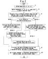
- Fig. 2 is a flowchart to explain texture correction processing by the image processing apparatus 51.
- the texture correction processing will be described in order of step numbers shown in Fig. 2 .
- Step S1 The fluctuation extraction section 52 obtains image data as a processing target.
- Fig. 3[A] is an example of the image data as the processing target.
- Each pixel of the image data here has signal components including brightness information Y and color difference information Cb, Cr.
- the relation of the signal components YCbCr with color components RGB generated by an electronic camera is expressed by, for example, the following equations.
- Y + 0.2990 ⁇ R + 0.5780 ⁇ G + 0.1140 ⁇ B
- Step S2 The fluctuation extraction section 52 smoothes each of the brightness information Y and the color difference information Cb, Cr in the image data by using an ⁇ filter or the like to obtain a smoothed image.
- Fig. 3[B] is a view showing an example of the smoothed image.
- Step S3 The fluctuation extraction section 52 calculates a pixel difference between the brightness information Y in the image data and brightness information having undergone the smoothing to find a local fluctuation of the brightness information, that is, a brightness fluctuation ⁇ Y. Further, the fluctuation extraction section 52 calculates a pixel difference between the color difference information Cb, Cr in the image data and color difference information having undergone the smoothing to find local fluctuations of the color difference information, that is, color difference fluctuations ⁇ Cb, ⁇ Cr.
- Step S5 The conversion section 54 obtains, as information, white balance coefficients (a gain Wr of the R component, a gain Wb of the B component) used when the image data is generated, from appended information or the like of the image data.
- white balance coefficients a gain Wr of the R component, a gain Wb of the B component
- an output level ratio of the RGB color components of an imaging device greatly varies depending on light source color temperature of the image data.
- a white balance coefficient for a color component is larger, its color signal is output from the imaging device with a smaller level and with a lower S/N. For this reason, it can be inferred that, a noise ratio ⁇ R : ⁇ G : ⁇ B among the color components included in the image data is substantially equal to a white balance coefficient ratio Wr : 1: Wb.
- the texture component D can be expressed as follows by using the fluctuations ⁇ R, ⁇ G, ⁇ B of the color components.
- Texture component D - 0.1687 ⁇ ⁇ + 0.5000 ⁇ ⁇ + 0.2990 ⁇ ⁇ R + - 0.3313 ⁇ ⁇ - 0.4187 ⁇ ⁇ + 0.5780 ⁇ ⁇ G + + 0.5000 ⁇ ⁇ - 0.0817 ⁇ ⁇ + 0.1140 ⁇ ⁇ B ⁇ L ⁇ R + M ⁇ G + N ⁇ B
- the color noise ratios of the color components included in the texture component D are substantially equal. That is, the weighting ratios ⁇ and ⁇ are decided so that the equation approximate to the following is obtained.
- the conversion section 54 calculates the solutions of the equations [6] based on the white balance coefficients to decide the weighting ratios ⁇ , ⁇ , After this decision, the conversion section 54 shifts its operation to Step S9.
- Step S6 The conversion section 54 inverse-transforms the signal components YCbCr of each pixel of the image data to restore values with which the color components RGB are thought to have generated in the imaging device.
- the conversion section 54 By locally smoothing the values of the color components RGB, it is possible to calculate local signal levels of the color components RGB.
- level-dependent noises such as shot noises occur. Therefore, the ratios of the color noises included in the texture component D also vary depending on the level-dependent noises. Therefore, based on the local signal levels RGB of the color components RGB, the conversion section 54 calculates the ratio ⁇ R : ⁇ G : ⁇ B of the level-dependent noises of the color components.
- the solutions ⁇ , ⁇ of the equations [8] are weighting ratios for making the ratios of the shot noises of the color components included in the texture component equal. In this manner, the conversion section 54 decides the weighting ratios ⁇ , ⁇ for each local area of the image data. After this decision, the conversion section 54 shifts its operation to Step S9.
- Step S7 The conversion section 54 obtains, as information, color correction coefficients of the image data from appended information or the like of the image data. For example, as saturation is emphasized more, a larger noise of a specific color component whose saturation is emphasized appears in the image data.
- the noise ratio ⁇ R : ⁇ G : ⁇ B among the color components included in the image data is expressed as follows, where Sr, Sg, and Sb are the color correction coefficients of the respective color components RGB.
- Step S8 The conversion section 54 inverse-transforms the signal components YCbCr of each pixel in the image data by using the inverse transformation of the equation [1] to obtain values of the color components RGB.
- the ratios of the color noises included in the texture component D also vary depending on level differences among the color components. For example, in a blue area close to the primary color in a screen, the signal level of the color component B becomes especially high. As a result, the color component B includes almost all the texture information of the blue area. On the other hand, in such a blue area, the signal level of the color component R is extremely low.
- the color component R includes little significant texture information and is mostly occupied by noises.
- the ratios of the color noises included in the texture component D vary depending on the level differences among the color components.
- the weighting ratios are adjusted so that a color component with a lower signal level has a less contribution ratio to the texture component D.
- the color noise ratio ⁇ R : ⁇ G: ⁇ B correlating with the level difference can be expressed by the following equation, where RGB are the local signal levels of the color components.
- the solutions ⁇ , ⁇ of the equations [12] are weighting ratios ⁇ , ⁇ in which the level differences among the color components are taken into consideration.
- the conversion section 54 calculates the solutions ⁇ , ⁇ for each area of the image data. After calculating all the weighting ratios ⁇ , ⁇ for the respective local areas, the conversion section 54 shifts its operation to Step S9.
- Step S9 The conversion section 54 weightedly adds the color difference fluctuations ⁇ Cr, ⁇ Cb to the brightness fluctuation ⁇ Y according to the weighting ratios ⁇ , ⁇ decided at any of Steps S5 - S8 ,and calculate the texture component D by the following equation.
- Texture component D ⁇ Y + ⁇ Cb + ⁇ Cr
- the addition section 55 adds the texture component D multiplied by a predetermined addition coefficient to the brightness information resulting from the smoothing (or the brightness information Y of the image data).
- the brightness fluctuation ⁇ Y has been amplitude-modulated in proportion to a tone conversion coefficient (gradient of a tone conversion curve) of the brightness information Y.
- the texture component D multiplied by a fixed addition coefficient is added to the brightness information, excessive texture and noise tend to occur in an image area with a large tone conversion coefficient. Therefore, by adjusting, locally or on a per pixel basis, the addition coefficient in substantially inverse proportion to the tone conversion coefficient, the addition of the texture component D can be performed properly.
- ⁇ Y brightness fluctuation
- the texture after the correction becomes richer than that in Fig. 3[C] by a degree corresponding to the texture emphasis using the color difference fluctuations.
- a specific color noise is mixed in the brightness information due to the texture correction, a noisy impression is given to this image, though not so great as that in Fig. 3[C] .
- the ratio of a noise of R (red) included in the texture component D is moderately reduced, a noisy impression in a fabric portion (blue) is successfully reduced.
- a second embodiment is an embodiment of an electronic camera.
- Fig. 4 is a block diagram showing the structure of an electronic camera 11.
- an imaging lens 12 is mounted in the electronic camera 11.
- a light-receiving surface of an imaging device 13 is disposed.
- the operation of the imaging device 1 3 is controlled by an output pulse of a timing generator 22b.
- An image generated by the imaging device 13 is temporarily stored in a buffer memory 17 via an A/D conversion section 1 5 and a signal processing section 16.
- the buffer memory 1 7 is coupled to a bus 18.
- an image processing section 19 To the bus 18, an image processing section 19, a card interface 20, a microprocessor 22, a compression/expansion section 23, an image display section 24 are coupled.
- the card interface 20 reads/writes data to/from a removable memory card 21. Further, a signal corresponding to a user's operation is input to the microprocessor 22 from a switch group 22a of the electronic camera 11. Further, the image display section 24 displays an image on a monitor screen 25 provided on a rear surface of the electronic camera 11.
- the texture correction of the first embodiment is executed by the microprocessor 22 and the image processing section 19. This texture correction may be applied to image data immediately after the shooting or may be applied later to the image data recorded in the memory card 21.
- an image processing server on the Internet may provide, as service, the image processing method for the texture correction to image data transmitted from a user.
- the texture correction is executed in the YCbCr color space.
- the present invention is not limited to this.
- the similar texture correction may be executed in the Lab color space, the HSV color space, or other color space.
- the texture emphasis is applied to the whole screen.
- the texture emphasis may be applied only to part of a screen (a main subject, a figure or skin-color area, a shaded part, a trimming range, a background part except a figure and skin-color area, and the like). In this case, it is possible to effectively emphasize the texture of a specific part in the screen while avoiding an adverse effect of noise increase on the whole screen.
- the embodiment is not limited to this.
- the smoothed color difference information may be obtained by subtracting the color difference fluctuation from the original color difference information. Further, for example, by subtracting the brightness fluctuation after adding the texture component to the original brightness information, it is possible to obtain brightness information with corrected texture.
- one of Steps S5 ⁇ S8 is selectively executed to decide the weighting ratios ⁇ , ⁇ .
- the embodiment is not limited to this.
- a plurality of steps out of Steps S5 ⁇ S8 may be executed to decide a plurality of kinds of weighting ratios.
- the present invention is an art usable for texture correction of an image, and the like.
Landscapes
- Engineering & Computer Science (AREA)
- Multimedia (AREA)
- Signal Processing (AREA)
- Image Processing (AREA)
- Processing Of Color Television Signals (AREA)
- Facsimile Image Signal Circuits (AREA)
Abstract
Description
- The present invention relates to an image processing apparatus, an image processing program, an image processing method, and an electronic camera.
- In conventional arts, if an electronic camera is set to high sensitivity (for example, an output gain of an imaging device is raised), noises of a shot image increases, so that the image becomes noisy and noises such as color speckles appear in the image. Such noises can be reduced by smoothing the image. However, excessive smoothing would damage a fine image structure of a subject, resulting in an image with poor texture.
- As an apparatus correcting such poor texture, an apparatus of the following
patent document 1 has been known.
In thepatent document 1, a minute amplitude component is extracted from image data by using an ε filter or the like, and the minute amplitude component is added to the image data. This prior art enables texture correction such as so-called "wrinkle emphasis". Patent Document 1: Japanese Unexamined Patent Application Publication No2001-118064 - In the prior art of the
patent document 1, even a minute amplitude component that should be removed as a noise is also directly added to the image data. This has posed a problem that a surface of a subject appears noisy due to the noise.
Therefore, a proposition of the present invention is to provide an image processing technique for correcting texture of an image while preventing worsening of a noisy impression. -
- «1» An image processing apparatus of the present invention includes a brightness fluctuation extraction section, a color difference fluctuation extraction section, a conversion section, and an addition section.
The brightness fluctuation extraction section extracts a local fluctuation component from brightness information (hereinafter, a brightness fluctuation) in the image data.
The color difference fluctuation extraction section extracts a local fluctuation component from color difference information (hereinafter, a color difference fluctuation) in the image data.
The conversion section weightedly adds the color difference fluctuation to the brightness fluctuation, and generates a pseudo texture component of brightness.
The addition section adds the generated texture component to the brightness information.
In the above-described structure, the conversion section adjusts and changes a weighting ratio of the weighted addition so as to make ratios of noises of color components included in the texture component substantially equal. - «2» Preferably, the conversion section obtains, as information, white balance coefficients used when the image data is generated, and calculates the weighting ratio for making the ratios of color noises correlating with the white balance coefficients equal.
- «3» Preferably, based on local signal levels of color components of the image data, the conversion section locally calculates the weighting ratio for making the ratios of level-dependent color noises included in the texture component equal.
- «4» Preferably, the conversion section obtains, as information, color correction coefficients of the image data, and calculates the weighting ratio for making the ratios of color noises correlating with the color correction coefficients equal.
- «5» Preferably, based on a level difference between local color signals of the image data, the conversion section calculates the weighting ratio for making the ratios of color noises correlating with the level difference equal.
- «6» Preferably, the addition section obtains, as information, a tone correction coefficient of the image data, and changes an addition coefficient of the texture component based on the tone correction coefficient.
- «7» An image processing program of the present invention is a program for causing a computer to function as the image processing apparatus according to any one of the above «1» ∼ «6».
- «8» An image processing method of the present invention is a method of applying image processing to image data including brightness information and color difference information, the method including the following steps.
- (1) A brightness fluctuation extraction step ... To extract a local fluctuation component from the brightness information (hereinafter, a brightness fluctuation) in the image data.
- (2) A color difference fluctuation extraction step ... To extract a local fluctuation component from the color difference information (hereinafter, a color difference fluctuation) in the image data.
- (3) A conversion step ... To weightedly add the color difference fluctuation to the brightness fluctuation, and generate a pseudo texture component of brightness.
- (4) An addition step ... To add the texture component to the brightness information.
The above conversion step adjusts and changes a weighting ratio of the weighted addition so as to make ratios of noises of color components included in the texture component substantially equal.
- «9» An electronic camera of the present invention includes the image processing apparatus according to any one of the above «1» ∼ «6», and an imaging section picking up an image of a subject to generate image data. In this electronic camera, the image processing apparatus applies image processing to the image data generated by the imaging section.
- In the present invention, the local fluctuation of the color difference information is reflected in the texture component of the brightness information, whereby a texture expression of the brightness information is enriched. Further, the weighting ratio for the color difference fluctuation is adjusted and changed to make the ratios of the color noises included in the texture component substantially equal. As a result, it is possible to prevent a noise of a specific color component from mixing in the texture component, which makes it possible to prevent a noise of the brightness information from worsening after the texture correction.
-
-
Fig. 1 is a block diagram showing an image processing apparatus 51. -
Fig. 2 is a flowchart to explain texture correction processing by the image processing apparatus 51. -
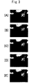
Figs. 3 are halftone images on a monitor, showing processes of the texture correction. -
Fig. 4 is a block diagram showing the structure of an electronic camera 11. -
Fig. 1 is a block diagram showing an image processing apparatus 51 of this embodiment.
InFig. 1 , the image processing apparatus 51 includes a fluctuation extraction section 52. The fluctuation extraction section 52 obtains brightness information and color difference information in image data to generate a brightness fluctuation and color difference fluctuations. The conversion section 54 weightedly adds the color difference fluctuations to the brightness fluctuation to generate a pseudo texture component of brightness. An addition section 55 applies texture correction to the brightness information by using the generated texture component.
Incidentally, these constituent elements may be realized as software by a computer executing an image processing program. Alternatively, the above-described constituent elements may be realized as hardware by arithmetic circuits or the like. -
Fig. 2 is a flowchart to explain texture correction processing by the image processing apparatus 51.
Hereinafter, the texture correction processing will be described in order of step numbers shown inFig. 2 . - Step S1: The fluctuation extraction section 52 obtains image data as a processing target.
Fig. 3[A] is an example of the image data as the processing target. Each pixel of the image data here has signal components including brightness information Y and color difference information Cb, Cr.
The relation of the signal components YCbCr with color components RGB generated by an electronic camera is expressed by, for example, the following equations.
- Step S2: The fluctuation extraction section 52 smoothes each of the brightness information Y and the color difference information Cb, Cr in the image data by using an ε filter or the like to obtain a smoothed image.
Fig. 3[B] is a view showing an example of the smoothed image. - Step S3: The fluctuation extraction section 52 calculates a pixel difference between the brightness information Y in the image data and brightness information having undergone the smoothing to find a local fluctuation of the brightness information, that is, a brightness fluctuation δY. Further, the fluctuation extraction section 52 calculates a pixel difference between the color difference information Cb, Cr in the image data and color difference information having undergone the smoothing to find local fluctuations of the color difference information, that is, color difference fluctuations δCb, δCr.
- Step S4: The conversion section 54 generates a pseudo texture component of brightness by the weighted addition according to the following equation.

- Step S5: The conversion section 54 obtains, as information, white balance coefficients (a gain Wr of the R component, a gain Wb of the B component) used when the image data is generated, from appended information or the like of the image data.
Generally, an output level ratio of the RGB color components of an imaging device greatly varies depending on light source color temperature of the image data. Here, in general, as a white balance coefficient for a color component is larger, its color signal is output from the imaging device with a smaller level and with a lower S/N. For this reason, it can be inferred that, a noise ratio δR : δG : δB among the color components included in the image data is substantially equal to a white balance coefficient ratio Wr : 1: Wb.


where t1 = 1 /Wr and t2 = 1 /Wb.
If the white balance coefficients are Wr = 2.0 and Wb = 1.47, for instance, the solutions of the equations [6] are α = 0.41 and β = 0.01. Therefore, by using these solutions α, β themselves or the weighting ratios α, β approximate to these solutions, it is possible to make the ratios of the noises of the color components included in the texture component D substantially equal.
In this manner, the conversion section 54 calculates the solutions of the equations [6] based on the white balance coefficients to decide the weighting ratios α, β, After this decision, the conversion section 54 shifts its operation to Step S9. - Step S6: The conversion section 54 inverse-transforms the signal components YCbCr of each pixel of the image data to restore values with which the color components RGB are thought to have generated in the imaging device. By locally smoothing the values of the color components RGB, it is possible to calculate local signal levels of the color components RGB.
Generally, in the imaging device, level-dependent noises such as shot noises occur. Therefore, the ratios of the color noises included in the texture component D also vary depending on the level-dependent noises.
Therefore, based on the local signal levels RGB of the color components RGB, the conversion section 54 calculates the ratio δR : δG : δB of the level-dependent noises of the color components.
For example, if shot noises occur, their noise amounts are proportional to square roots of the local color components RGB generated in the imaging device (generated charge amounts), and therefore, the following relation holds.

where t1 = √(G/R), t2=√(G/B).
Note that lower limit values of the values of R, G, and B are limited so as not to become zero.
The solutions α, β of the equations [8] are weighting ratios for making the ratios of the shot noises of the color components included in the texture component equal.
In this manner, the conversion section 54 decides the weighting ratios α, β for each local area of the image data. After this decision, the conversion section 54 shifts its operation to Step S9. - Step S7: The conversion section 54 obtains, as information, color correction coefficients of the image data from appended information or the like of the image data.
For example, as saturation is emphasized more, a larger noise of a specific color component whose saturation is emphasized appears in the image data. In this case, it is inferred that the noise ratio δR : δG : δB among the color components included in the image data is expressed as follows, where Sr, Sg, and Sb are the color correction coefficients of the respective color components RGB.

where t1 = Sg/Sr and t2 = Sg/Sb. Note that lower limit values of the values of Sr, Sg, Sb are limited so as not to become zero.
The solutions α, β of the equations [10] are weighting ratios for making changes in the color noise ratios in the texture component D accompanying the saturation correction equal.
In this manner, the conversion section 54 decides the weighting ratios α, β based on the color correction coefficients. After this decision, the conversion section 54 shifts its operation to Step S9. - Step S8: The conversion section 54 inverse-transforms the signal components YCbCr of each pixel in the image data by using the inverse transformation of the equation [1] to obtain values of the color components RGB. By locally smoothing the values of the color components RGB, it is possible to calculate local signal levels of the color components RGB. The ratios of the color noises included in the texture component D also vary depending on level differences among the color components.
For example, in a blue area close to the primary color in a screen, the signal level of the color component B becomes especially high. As a result, the color component B includes almost all the texture information of the blue area.
On the other hand, in such a blue area, the signal level of the color component R is extremely low. Therefore, the color component R includes little significant texture information and is mostly occupied by noises.
As described above, the ratios of the color noises included in the texture component D vary depending on the level differences among the color components. In order to make the ratios of the color noises equal, the weighting ratios are adjusted so that a color component with a lower signal level has a less contribution ratio to the texture component D.
For example, it can be inferred that the color noise ratio δR : δG: δB correlating with the level difference can be expressed by the following equation, where RGB are the local signal levels of the color components.
By using the equation [11] instead of the equation [3] used at Step S5, the following simultaneous equations for αβ are obtained,
where t1 = R/G and t2 = B/G. Note that lower limit values of R, G, and B are limited so as not to become zero.
The solutions α, β of the equations [12] are weighting ratios α, β in which the level differences among the color components are taken into consideration. The conversion section 54 calculates the solutions α, β for each area of the image data. After calculating all the weighting ratios α, β for the respective local areas, the conversion section 54 shifts its operation to Step S9. - Step S9: The conversion section 54 weightedly adds the color difference fluctuations δCr, δCb to the brightness fluctuation δY according to the weighting ratios α, β decided at any of Steps S5 - S8 ,and calculate the texture component D by the following equation.

The brightness fluctuation δY has been amplitude-modulated in proportion to a tone conversion coefficient (gradient of a tone conversion curve) of the brightness information Y. Therefore, if the texture component D multiplied by a fixed addition coefficient is added to the brightness information, excessive texture and noise tend to occur in an image area with a large tone conversion coefficient. Therefore, by adjusting, locally or on a per pixel basis, the addition coefficient in substantially inverse proportion to the tone conversion coefficient, the addition of the texture component D can be performed properly. -
Fig. 3[C] is an image to which texture emphasis is applied by using only the brightness fluctuation δY (weighting ratios for the color difference fluctuations α = 0, β = 0).
In this case, as the degree of the texture emphasis is increased, image noise prominently increases, resulting in an image having a noisy impression. - Further,
Fig. 3[D] is an image to which the texture emphasis is applied with the weighting ratios α, β being set equal (α = β = 0.27). In this case, the texture after the correction becomes richer than that inFig. 3[C] by a degree corresponding to the texture emphasis using the color difference fluctuations. However, since a specific color noise is mixed in the brightness information due to the texture correction, a noisy impression is given to this image, though not so great as that inFig. 3[C] . -
Fig. 3[E] is an image resulting from the processing in which the ratios of the color noises of the color components included in the texture component D are made substantially equal (α = 0.45, β = 0.09) as in the above-described first embodiment. In this case, since the ratio of a noise of R (red) included in the texture component D is moderately reduced, a noisy impression in a fabric portion (blue) is successfully reduced. - A second embodiment is an embodiment of an electronic camera.
Fig. 4 is a block diagram showing the structure of an electronic camera 11.
InFig. 4 , animaging lens 12 is mounted in the electronic camera 11. In an image space of theimaging lens 12, a light-receiving surface of an imaging device 13 is disposed. The operation of theimaging device 1 3 is controlled by an output pulse of a timing generator 22b.
An image generated by the imaging device 13 is temporarily stored in abuffer memory 17 via an A/D conversion section 1 5 and asignal processing section 16.
Thebuffer memory 1 7 is coupled to abus 18. To thebus 18, animage processing section 19, acard interface 20, amicroprocessor 22, a compression/expansion section 23, animage display section 24 are coupled. Among these, thecard interface 20 reads/writes data to/from aremovable memory card 21. Further, a signal corresponding to a user's operation is input to themicroprocessor 22 from a switch group 22a of the electronic camera 11. Further, theimage display section 24 displays an image on amonitor screen 25 provided on a rear surface of the electronic camera 11.
In the electronic camera 11 as structured above, the texture correction of the first embodiment is executed by themicroprocessor 22 and theimage processing section 19.
This texture correction may be applied to image data immediately after the shooting or may be applied later to the image data recorded in thememory card 21. - The above embodiments describe the case where the texture emphasis is executed by using the image processing apparatus 51 or the electronic camera 11. However, the present invention is not limited to this. For example, an image processing server on the Internet may provide, as service, the image processing method for the texture correction to image data transmitted from a user.
- The above embodiments describe the case where the texture correction is executed in the YCbCr color space. However, the present invention is not limited to this. For example, the similar texture correction may be executed in the Lab color space, the HSV color space, or other color space.
- The above embodiments describe the case where the texture emphasis is applied to the whole screen. However, the present invention is not limited to this. For example, the texture emphasis may be applied only to part of a screen (a main subject, a figure or skin-color area, a shaded part, a trimming range, a background part except a figure and skin-color area, and the like). In this case, it is possible to effectively emphasize the texture of a specific part in the screen while avoiding an adverse effect of noise increase on the whole screen.
- Further, in the above embodiment, it is preferable to output the color difference information after it is smoothed and output the result of the addition of the texture component D to the smoothed brightness information. However, the embodiment is not limited to this. For example, the smoothed color difference information may be obtained by subtracting the color difference fluctuation from the original color difference information. Further, for example, by subtracting the brightness fluctuation after adding the texture component to the original brightness information, it is possible to obtain brightness information with corrected texture.
- In the above embodiment, one of Steps S5 ∼ S8 is selectively executed to decide the weighting ratios α, β. However, the embodiment is not limited to this. For example, a plurality of steps out of Steps S5 ∼ S8 may be executed to decide a plurality of kinds of weighting ratios. In this case, by taking an average or a weighted average of the plural kinds of weighting ratios, it is possible to calculate the weighting ratios α, β in which the equalization of a plurality of kinds of noises is taken into consideration.
- It should be noted that the present invention can be implemented in other various forms without departing from its spirit and main features. Therefore, the above-described embodiments are only examples in all respects and should not be interpreted limitedly. The scope of the present invention is to be specified by the scope of the claims, and is in no way limited by the description in the specification. Further, modifications and alterations belonging to the scope equivalent to the scope of the claims are all embraced in the scope of the present invention.
- As described above, the present invention is an art usable for texture correction of an image, and the like.
Claims (9)
- An image processing apparatus comprising:a brightness fluctuation extraction section extracting a local fluctuation component from brightness information (hereinafter, a brightness fluctuation) in the image data;a color difference fluctuation extraction section extracting a local fluctuation component from color difference information (hereinafter, a color difference fluctuation) in said image data;a conversion section weightedly adding said color difference fluctuation to said brightness fluctuation, and generating a pseudo texture component of brightness; andan addition section adding said texture component to said brightness information, whereinsaid conversion section adjusts and changes a weighting ratio of said weighted addition so as to make ratios of color noises of color components included in said texture component substantially equal.
- The image processing apparatus according to claim 1, wherein
said conversion section obtains, as information, white balance coefficients used when said image data is generated, and calculates said weighting ratio for making said ratios of color noises correlating with said white balance coefficients equal. - The image processing apparatus according to claim 1, wherein
based on local signal levels of color components of said image data, said conversion section locally calculates the weighting ratio for making the ratios of level-dependent color noises included in said texture component equal. - The image processing apparatus according to claim 1, wherein
said conversion section obtains, as information, color correction coefficients of said image data, and calculates said weighting ratio for making said ratios of color noises correlating with said color correction coefficients equal. - The image processing apparatus according to claim 1, wherein
based on a level difference between local color components of said image data, said conversion section calculates said weighting ratio for making said ratios of color noises correlating with said level difference equal. - The image processing apparatus according to any one of claim 1 to claim 5, wherein
said addition section obtains, as information, a tone correction coefficient of said image data, and changes an addition coefficient of said texture component based on said tone correction coefficient. - An image processing program for causing a computer to function as the image processing apparatus according to any one of claim 1 to claim 6.
- An image processing method of applying image processing to image data including brightness information and color difference information, the method comprising:a brightness fluctuation extraction step of extracting a local fluctuation component from said brightness information (hereinafter, a brightness fluctuation) in said image data;a color difference fluctuation extraction step of extracting a local fluctuation component from said color difference information (hereinafter, a color difference fluctuation) in said image data;a conversion step of weightedly adding said color difference fluctuation to said brightness fluctuation, and generating a pseudo texture component of brightness;an addition step of adding said texture component to said brightness information, whereinsaid conversion step adjusts and changes a weighting ratio of said weighted addition so as to make ratios of noises of said color components included in said texture component substantially equal.
- An electronic camera comprising:the image processing apparatus according to any one of claim 1 to claim 6; andan imaging section picking up an image of a subject to generate image data, whereinsaid image processing apparatus applies image processing to the image data generated by said imaging section.
Applications Claiming Priority (2)
| Application Number | Priority Date | Filing Date | Title |
|---|---|---|---|
| JP2006050221 | 2006-02-27 | ||
| PCT/JP2007/000126 WO2007097125A1 (en) | 2006-02-27 | 2007-02-26 | Image processing device for correcting image massive feeling, image processing program, image processing method, and electronic camera |
Publications (2)
| Publication Number | Publication Date |
|---|---|
| EP1991008A1 true EP1991008A1 (en) | 2008-11-12 |
| EP1991008A4 EP1991008A4 (en) | 2012-04-18 |
Family
ID=38437169
Family Applications (1)
| Application Number | Title | Priority Date | Filing Date |
|---|---|---|---|
| EP20070713508 Withdrawn EP1991008A4 (en) | 2006-02-27 | 2007-02-26 | Image processing device for correcting image massive feeling, image processing program, image processing method, and electronic camera |
Country Status (4)
| Country | Link |
|---|---|
| US (1) | US8040387B2 (en) |
| EP (1) | EP1991008A4 (en) |
| JP (1) | JP4752912B2 (en) |
| WO (1) | WO2007097125A1 (en) |
Families Citing this family (5)
| Publication number | Priority date | Publication date | Assignee | Title |
|---|---|---|---|---|
| WO2009081485A1 (en) * | 2007-12-25 | 2009-07-02 | Fujitsu Limited | Image processing apparatus, image processing method and image processing program |
| GB2483433A (en) * | 2010-08-31 | 2012-03-14 | Sony Corp | 3D image adjustment based on differences in colour properties between stereo pair |
| JP5810593B2 (en) * | 2011-04-08 | 2015-11-11 | 株式会社ニコン | Image processing apparatus, imaging apparatus, and program |
| JP2015056013A (en) * | 2013-09-11 | 2015-03-23 | 株式会社リコー | Image processing device |
| CN108881875B (en) * | 2018-08-16 | 2020-01-14 | Oppo广东移动通信有限公司 | Image white balance processing method and device, storage medium and terminal |
Family Cites Families (28)
| Publication number | Priority date | Publication date | Assignee | Title |
|---|---|---|---|---|
| JPS6364494A (en) * | 1986-09-04 | 1988-03-22 | Sony Corp | Feedback type noise reducer |
| JPH0236675A (en) | 1988-07-27 | 1990-02-06 | Nec Corp | Method and circuit for picture emphasis |
| JPH0345095A (en) * | 1989-07-13 | 1991-02-26 | Toshiba Corp | Picture contour exaggeration circuit |
| JPH0576034A (en) * | 1991-09-10 | 1993-03-26 | Toshiba Corp | Picture signal processor |
| US5760843A (en) * | 1993-01-19 | 1998-06-02 | Matsushita Electric Industrial Co., Ltd. | Method and apparatus for contrast processing a video signal including brightness level compensation |
| JP3270609B2 (en) * | 1993-01-19 | 2002-04-02 | 松下電器産業株式会社 | Image display method and apparatus |
| JP3196423B2 (en) * | 1993-06-03 | 2001-08-06 | 松下電器産業株式会社 | High chroma image detail compensation circuit |
| JP3381755B2 (en) * | 1994-10-11 | 2003-03-04 | セイコーエプソン株式会社 | Method and apparatus for improved adaptive filtering and thresholding to reduce image graininess |
| JP3003561B2 (en) * | 1995-09-25 | 2000-01-31 | 松下電器産業株式会社 | Gradation conversion method and circuit, image display method and apparatus, and image signal conversion apparatus |
| JP4274590B2 (en) | 1997-01-20 | 2009-06-10 | オリンパス株式会社 | Image processing device |
| JPH11250246A (en) * | 1998-02-27 | 1999-09-17 | Fuji Photo Film Co Ltd | Image processing method and apparatus |
| US6667815B1 (en) * | 1998-09-30 | 2003-12-23 | Fuji Photo Film Co., Ltd. | Method and apparatus for processing images |
| JP4626007B2 (en) * | 1999-06-14 | 2011-02-02 | 株式会社ニコン | Image processing method, machine-readable recording medium storing image processing program, and image processing apparatus |
| US6621937B1 (en) * | 1999-10-08 | 2003-09-16 | Eastman Kodak Company | Removing chroma noise from digital images by using variable shape pixel neighborhood regions |
| JP3319727B2 (en) | 1999-10-20 | 2002-09-03 | 日本放送協会 | Image processing device |
| JP3596410B2 (en) | 2000-03-01 | 2004-12-02 | 日本電気株式会社 | Image signal processing apparatus and processing method thereof |
| JP2002044678A (en) | 2000-07-19 | 2002-02-08 | Sony Corp | Color video signal converter |
| JP3726653B2 (en) * | 2000-07-27 | 2005-12-14 | ノーリツ鋼機株式会社 | Image processing method, image processing apparatus, and recording medium on which program for executing image processing method is recorded |
| JP4666274B2 (en) * | 2001-02-20 | 2011-04-06 | 日本電気株式会社 | Color image processing apparatus and method |
| JP4086479B2 (en) | 2001-03-23 | 2008-05-14 | Necディスプレイソリューションズ株式会社 | Image quality improving apparatus and image quality improving method |
| WO2003010180A1 (en) * | 2001-07-23 | 2003-02-06 | The Board Of Trustees Of The Leland Stanford Junior University | Methods and compositions for rnai mediated inhibition of gene expression in mammals |
| JP4197858B2 (en) * | 2001-08-27 | 2008-12-17 | 富士通株式会社 | Image processing program |
| US7292733B2 (en) * | 2002-10-16 | 2007-11-06 | Matsushita Electric Industrial Co., Ltd. | Image processing apparatus and image processing method |
| EP1708490B1 (en) * | 2003-12-03 | 2013-02-13 | Nikon Corporation | Image processing device for controlling intensity of noise removal in a screen, image processing program, image processing method, and electronic camera |
| JP4385748B2 (en) * | 2003-12-05 | 2009-12-16 | パナソニック株式会社 | Image signal processing apparatus and image signal processing method |
| US7382915B2 (en) * | 2004-03-16 | 2008-06-03 | Xerox Corporation | Color to grayscale conversion method and apparatus |
| JP4468734B2 (en) * | 2004-04-27 | 2010-05-26 | オリンパス株式会社 | Video signal processing apparatus and video signal processing program |
| US7924288B2 (en) | 2004-06-22 | 2011-04-12 | Nikon Corporation | Image processing device emphasizing on texture, image processing program, electronic camera, and image processing method |
-
2007
- 2007-02-26 WO PCT/JP2007/000126 patent/WO2007097125A1/en not_active Ceased
- 2007-02-26 JP JP2008501638A patent/JP4752912B2/en not_active Expired - Fee Related
- 2007-02-26 EP EP20070713508 patent/EP1991008A4/en not_active Withdrawn
-
2008
- 2008-07-11 US US12/216,883 patent/US8040387B2/en active Active
Also Published As
| Publication number | Publication date |
|---|---|
| JP4752912B2 (en) | 2011-08-17 |
| EP1991008A4 (en) | 2012-04-18 |
| WO2007097125A1 (en) | 2007-08-30 |
| US20090046166A1 (en) | 2009-02-19 |
| JPWO2007097125A1 (en) | 2009-07-09 |
| US8040387B2 (en) | 2011-10-18 |
Similar Documents
| Publication | Publication Date | Title |
|---|---|---|
| US8600154B2 (en) | Image processing apparatus and image processing method | |
| KR101247646B1 (en) | Image combining apparatus, image combining method and recording medium | |
| US7599578B2 (en) | Apparatus, program, and method for image tone transformation, and electronic camera | |
| US8385680B2 (en) | Image processing apparatus and image processing method | |
| US6842536B2 (en) | Image processing apparatus, image processing method and computer program product for correcting image obtained by shooting subject | |
| EP2624204B1 (en) | Image processing apparatus and method of controlling the same | |
| US8254675B2 (en) | Image processing apparatus, imaging apparatus and image processing program | |
| EP1898624B1 (en) | Image processing device, image processing method, image processing program product, and image-capturing device | |
| US8831346B2 (en) | Image processing apparatus and method, and program | |
| EP1930853A1 (en) | Image signal processing apparatus and image signal processing | |
| US8041148B2 (en) | Recording medium storing image processing program and image processing method | |
| JP4321064B2 (en) | Image processing apparatus and image processing program | |
| US8040387B2 (en) | Image processing apparatus, image processing program, image processing method, and electronic camera for correcting texture of image | |
| US7755670B2 (en) | Tone-conversion device for image, program, electronic camera, and tone-conversion method | |
| CN102223480A (en) | Image processing device and image processing method | |
| US20080212892A1 (en) | Image Processing Device, Computer Program Product , and Image Processing Method | |
| US7733390B2 (en) | Image-processing devices, methods, and programs, and electronic cameras and the like comprising same | |
| US9098886B2 (en) | Apparatus and method for processing an image | |
| US8570407B2 (en) | Imaging apparatus, image processing program, image processing apparatus, and image processing method | |
| US7453524B2 (en) | Method and device for image contrast enhancement | |
| US7924288B2 (en) | Image processing device emphasizing on texture, image processing program, electronic camera, and image processing method | |
| EP1895781B1 (en) | Method of and apparatus for adjusting colour saturation | |
| US8665351B2 (en) | Image processing device, electronic camera, and storage medium storing image processing program | |
| JP2012222616A (en) | Image processing device, imaging device, and program | |
| JP4176023B2 (en) | Signal processing circuit |
Legal Events
| Date | Code | Title | Description |
|---|---|---|---|
| PUAI | Public reference made under article 153(3) epc to a published international application that has entered the european phase |
Free format text: ORIGINAL CODE: 0009012 |
|
| 17P | Request for examination filed |
Effective date: 20080924 |
|
| AK | Designated contracting states |
Kind code of ref document: A1 Designated state(s): AT BE BG CH CY CZ DE DK EE ES FI FR GB GR HU IE IS IT LI LT LU LV MC NL PL PT RO SE SI SK TR |
|
| RAP1 | Party data changed (applicant data changed or rights of an application transferred) |
Owner name: NIKON CORPORATION |
|
| A4 | Supplementary search report drawn up and despatched |
Effective date: 20120316 |
|
| RIC1 | Information provided on ipc code assigned before grant |
Ipc: H04N 1/46 20060101ALI20120312BHEP Ipc: H04N 1/60 20060101ALI20120312BHEP Ipc: H04N 5/208 20060101ALI20120312BHEP Ipc: H04N 9/68 20060101AFI20120312BHEP Ipc: G06T 1/00 20060101ALI20120312BHEP |
|
| DAX | Request for extension of the european patent (deleted) | ||
| 17Q | First examination report despatched |
Effective date: 20130322 |
|
| GRAP | Despatch of communication of intention to grant a patent |
Free format text: ORIGINAL CODE: EPIDOSNIGR1 |
|
| RIC1 | Information provided on ipc code assigned before grant |
Ipc: H04N 9/73 20060101ALI20150212BHEP Ipc: H04N 1/58 20060101AFI20150212BHEP |
|
| INTG | Intention to grant announced |
Effective date: 20150311 |
|
| RAP1 | Party data changed (applicant data changed or rights of an application transferred) |
Owner name: NIKON CORPORATION |
|
| STAA | Information on the status of an ep patent application or granted ep patent |
Free format text: STATUS: THE APPLICATION IS DEEMED TO BE WITHDRAWN |
|
| 18D | Application deemed to be withdrawn |
Effective date: 20150722 |