EP1990927A1 - Mobile communication system receiver, path following method, and control program thereof - Google Patents
Mobile communication system receiver, path following method, and control program thereof Download PDFInfo
- Publication number
- EP1990927A1 EP1990927A1 EP07737425A EP07737425A EP1990927A1 EP 1990927 A1 EP1990927 A1 EP 1990927A1 EP 07737425 A EP07737425 A EP 07737425A EP 07737425 A EP07737425 A EP 07737425A EP 1990927 A1 EP1990927 A1 EP 1990927A1
- Authority
- EP
- European Patent Office
- Prior art keywords
- path
- paths
- adjacent
- tracking
- priority orders
- Prior art date
- Legal status (The legal status is an assumption and is not a legal conclusion. Google has not performed a legal analysis and makes no representation as to the accuracy of the status listed.)
- Withdrawn
Links
- 238000000034 method Methods 0.000 title claims abstract description 15
- 238000010295 mobile communication Methods 0.000 title claims description 18
- 239000000284 extract Substances 0.000 claims description 8
- 238000005070 sampling Methods 0.000 description 5
- 238000000926 separation method Methods 0.000 description 5
- 238000001228 spectrum Methods 0.000 description 5
- 238000006243 chemical reaction Methods 0.000 description 4
- 239000000470 constituent Substances 0.000 description 4
- 230000000694 effects Effects 0.000 description 4
- 238000000605 extraction Methods 0.000 description 4
- 238000004891 communication Methods 0.000 description 3
- 238000007796 conventional method Methods 0.000 description 2
- 238000010586 diagram Methods 0.000 description 2
- 238000005562 fading Methods 0.000 description 2
- 230000000644 propagated effect Effects 0.000 description 2
- 238000001514 detection method Methods 0.000 description 1
- 230000002542 deteriorative effect Effects 0.000 description 1
- 239000000126 substance Substances 0.000 description 1
- 230000001360 synchronised effect Effects 0.000 description 1
Images





Classifications
-
- H—ELECTRICITY
- H04—ELECTRIC COMMUNICATION TECHNIQUE
- H04B—TRANSMISSION
- H04B1/00—Details of transmission systems, not covered by a single one of groups H04B3/00 - H04B13/00; Details of transmission systems not characterised by the medium used for transmission
- H04B1/69—Spread spectrum techniques
- H04B1/707—Spread spectrum techniques using direct sequence modulation
- H04B1/7097—Interference-related aspects
- H04B1/711—Interference-related aspects the interference being multi-path interference
- H04B1/7115—Constructive combining of multi-path signals, i.e. RAKE receivers
- H04B1/7117—Selection, re-selection, allocation or re-allocation of paths to fingers, e.g. timing offset control of allocated fingers
Definitions
- the present invention relates to a mobile communication system receiver, a path tracking method, and a control program thereof. More specifically, the present invention relates to a receiver in a mobile communication system having a fine multipath tracking function, and to a path tracking method as well as a control program thereof.
- the information bit string is modulated into spread spectrum signals by spreading the string with spread codes, and the modulated signals in a form of radio signals are transmitted to the receiver side for achieving communication.
- DS-CDMA mode Direct Sequence Code Division Multiple Access
- Chip rate of the spread codes used in the DS-CDMA mode is a sufficiently high rate for a signal rate of the information bit string, and it is selected as a sufficiently high rate for propagation delay time between a mobile terminal device and a base station.
- each of the separated DS-CDMA signals having different propagation delay time is referred to as a multipath signal. It is well-known that a path diversity effect can be obtained and receiver gain can be improved through performing demodulation by allocating respective finger receiver units to the separated multipath signals and performing rake combining of each demodulated signal.
- FIG. 10 shows an example where there are three paths in the delay profile.
- the horizontal axis in FIG. 10 represents relative propagation delay time, and the longitudinal axis represents signal powers.
- Reference numeral 301 in FIG. 10 indicates a noise level, and it is assumed that there exists an effective path when the signal power is at a peak position 302 for the noise level 301.
- the aforementioned finger receiver is allocated and demodulation is performed.
- a measure is taken to prevent allocation of other finger receivers to the vicinity of the allocated path, i.e., a measure is taken to set a mask region to the vicinity of the path to which the finger receiver is allocated so as to prevent allocation of other finger receivers to the path to which the mask region is set.
- state of the propagation paths is constantly fluctuated in the mobile telecommunications, i.e., fluctuation occurs constantly in the delay profile.
- the delay profile is updated periodically. If it becomes necessary as a result thereof, tracking processing is performed for the path whose propagation delay is fluctuated, or update processing of the allocation of the finger receivers for emerging paths and fading paths is performed. For that, as shown in FIG.
- a method which performs the path tracking processing and the update processing of path allocation to the finger receivers by setting a path tracking region 303 for searching fluctuation of signal power peak positions, and mask regions 304 for preventing allocation of other finger receivers to the vicinity of the path that has been allocated to a finger receiver on the delay profile.
- Patent document 1 discloses a synchronous tracking method in a spread spectrum communication system having a path search function.
- a delay profile measuring device, an extracting device for extracting path timing signals from the delay profile, and a path identifying device for identifying a subordinate path group and an independent path are used for the path tracking operation.
- the path identifying device contains a threshold value setting device that is capable of setting a threshold value, and identifies each path with the path timing signal that has a value equal to or higher than the threshold value( e.g., each path with the path timing signals within ⁇ 1-chip time length) as a subordinate path group.
- Patent Document 1 Japanese Unexamined Patent Publication 2001-313590
- path tracking operations cannot be done in the right direction for the path 305, in both directions for the path 306, and in the left direction for the path 307.
- incapability of path tracking operations occurs continuously in fluctuation of the delay profile, in particular, the reception quality deteriorates. Finally, it may result in disconnection of calls.
- Patent Document 1 for identifying whether the paths in the delay profile are subordinate path group or independent path, it is judged whether the paths are the subordinate group or not only depending on the presence of the path timing signals but no other factors are considered for grouping the paths. That is, it is not designed to perform grouping of the paths other than the aforementioned manner.
- the present invention is designed in view of the foregoing circumstances, and it is an object of the present invention to provide a path tracking method and a receiver which are used in spread spectrum communications for improving the path tracking performance for a plurality of multipaths.
- a receiving mechanism in a mobile communication system includes: a path tracking processing function of detecting signal power peaks from a delay profile of multipath multiplexed signals received via a plurality of propagation paths, separating/extracting each path contained in the multipaths based on propagation delay of the detected signal power peaks, allocating finger receivers to the signals of each of the separated/extracted paths for performing demodulation as well as rake combine of each demodulated signal, updating the delay profile every prescribed time interval for tracking chronological changes of the propagation paths, when a signal power peak position within a path tracking region set in advance for each path is fluctuated, estimating that the path is fluctuated, and performing tracking of the fluctuated path; and a mask region setting function of setting mask regions for preventing other finger receivers than the reception finger receivers to the path from being allocated to the vicinity of the path when performing the path tracking processing, wherein, when the finger receivers are allocated to each of the paths of the multipaths in which each of the
- the path tracking region may be set for each path to perform a tracking operation of the path, and the mask regions may be set for the path after completing the tracking operation.
- the grouping processing may be performed every time the tracking operation of a single path is performed.
- the grouping processing may also be performed when the tracking operations of all the assumed multipaths are completed.
- the grouping processing may also be performed to put each of the adjacent paths when "Td ⁇ 2(Tt+Tm)" applies, provided that a propagation delay time difference of the adjacent paths is "Td", a half of time length of the path tracking region is "Tt", and time length of the mask region is "Tm”.
- the grouping processing may also be performed to put each of the adjacent paths into a group, when the propagation delay time difference of the adjacent paths is within prescribed time that is set in advance.
- the priority orders may be so set that the path having the maximum signal power within the group is given the highest priority, or may be set in order from the path having the higher signal power to the path having the lower signal power.
- the priority orders may be set in order of time at which separation/extraction of the paths is executed, or may be set in order of executing separation/extraction of the paths from the latest to the oldest.
- the path tracking operations for the remaining paths may be executed by setting the path tracking regions and the mask regions for the paths uniformly.
- the path tracking regions and the mask regions may be set for the remaining paths to perform the path tracking operations.
- a path tracking method of a mobile communication system which: detects signal power peaks from a delay profile of multipath multiplexed signals received via a plurality of propagation paths; separates/extracts each path contained in the multipaths based on propagation delay of the detected signal power peaks; allocates finger receivers to the signals of each of the separated/extracted paths for performing demodulation as well as rake combine of each demodulated signal; updates the delay profile every prescribed time interval for tracking chronological changes of the propagation paths; when a signal power peak position within a path tracking region set in advance for each path is fluctuated, assumes that the path is fluctuated; and sets a path tracking region to the fluctuated path and sets mask regions for preventing other finger receivers than the finger receivers allocated to the path from being allocated to the vicinity of the path, wherein, when the finger receivers are allocated to each of the paths of the multipaths in which each of the paths is close to each other in terms of time, each of the constituent paths is put into a group, priority orders
- the path tracking processing performed according to the priority orders may be executed by setting the path tracking region and the mask regions for each path.
- the path tracking region may be set for each path to perform the tracking operation of the path, and the mask regions may be set for the path after completing the tracking operation.
- the path tracking processing may be executed after completing the tracking operations of all the assumed multipaths.
- the grouping processing may also be performed to put each of the adjacent paths when "Td ⁇ 2(Tt+Tm)" applies, provided that a propagation delay time difference of the adjacent paths is "Td", a half of time length of the path tracking region is “Tt", and time length of the mask region is "Tm”.
- the grouping processing may also be performed to put each of the adjacent paths into a group, when the propagation delay time difference of the adjacent paths is within a prescribed time that is set in advance.
- the priority orders are set so that the path having the maximum signal power within the group is given the highest priority.
- the priority orders may be set in order from the path having the higher signal power to the path having the lower signal power.
- the priority orders may be set in order of time at which separation/extraction of the paths is executed, or may be set in order of executing separation/extraction of the paths from the latest to the oldest.
- the path tracking operation for the remaining paths may be executed by setting the path tracking regions and the mask regions for the paths uniformly.
- the path tracking regions and the mask regions may be set for the remaining paths to perform the path tracking operations.
- the present invention for performing the tracking operations of the paths fluctuated in accordance with chronological changes of the propagation paths at the time of receiving multipath multiplexed signals, when finger receivers are allocated to each of the paths of the multipaths close to each other in terms of time, the paths are put into a group, priority orders for performing the tracking operations are given to each path within the group, and path tracking processing is performed according to the priority orders. Therefore, the path tracking operations can be prevented from becoming incapable because of the mask regions, so that the reception qualities can be improved.
- a mobile communication system receiver is a receiver which, based on a delay profile of multipath multiplexed signals to be received, separates/extracts each path contained in multipaths, demodulates received signals by each of the separated paths, and performs rake combine on the demodulated signals.
- the receiver separates/extracts each path contained in the multipaths and allocates demodulation finger receivers to the separated/extracted paths, and sets priority orders for paths in an adjacent path group having small propagation delay time separated/extracted from the multipaths to eliminate interference generated between adjacent paths according to the priority orders, and performs path tracking processing.
- a path tracking region PC is set as a region for tracking a position to be the peak of the signal power value
- mask regions MS are set in side lobes of the path tracking region PC.
- “2Tt” indicates time length of the path tracking region PC
- “2Tm” indicates time length of the mask regions MS.
- the grouping unit 22 assumes the position where the signal power value in the delay profile becomes the peak as the position of the path, and performs aforementioned grouping processing based on the assumed result.
- the path tracking processing unit 26 performs the processing to judge whether or not there is time shift generated in the peak positions of the signal power value of the paths 202, 203, and 204 before and after updating, based on the information with which the grouping unit 22 assumes the peak positions in the delay profile as the paths 202, 203, 204, and the information with which the grouping unit 22 assumes the peak positions in the updated delay profile as the paths 202, 203, 204, by a path unit according to the priority orders.
- the path tracking processing unit 26 sets the priority orders in order of the path 203, the path 204, and the path 202, and performs the path tracking processing for the path 203 first, then performs the path tracking processing for the path 204, and performs the path tracking processing for the path 202 last.
- the finger reception unit 16 performs CDMA code demodulation (despread) of the receiving signals for each path according to an instruction from the path allocation unit 14.
- the rake combine unit 18 performs rake combine of the demodulated signals for each path from each of the finger reception units 16, and outputs the CDMA demodulation signal.
- the CDMA receiver according to the first exemplary embodiment is built as hardware. However, it is not limited only to such a case. It may be built as software for allowing a CPU of a computer configuring the CDMA receiver to execute each of the above-described functions of the delay profile unit 12, the path allocation unit 14, the finger reception unit 16, and the rake combine unit 18 based on a control program.
- the delay profile creation unit 12 updates the previous delay profile, extracts each path contained in the multipaths based on the updated delay profile, performs path tracking processing for the extracted paths, and updates the allocation of the finger reception units 16 for the paths to which the path processing is performed.
- the paths 201, 202, 203, and 204 are assumed as the paths at the positions of the signal power value peaks in the updated delay profile.
- 201a, 202a, 203a, and 204a are the points assumed as the paths at the positions of the signal power value peaks in the delay profile before being updated.
- unit sampling time Tt for specifying the path tracking region for the path is set on the left and right sides with respect to the peak position of the path signal power value, and the path tracking region is set as sampling time 2Tt.
- Unit sampling time Tm for specifying the mask region is set on the outer sides of the path tracking region, respectively, and the mask regions are set as sampling time 2Tm. While FIG.
- the propagation delay time difference of the path 202 with respect to the path 201 is propagation delay time Td.
- the propagation delay time difference Td also exists between the path 202 and the path 203 as well as between the path 203 and the path 204, although the lengths thereof vary.
- the grouping unit 22 calculates the propagation delay time difference Td between the first path 201 and the succeeding path 202 shown in FIG. 4 (step S1 of FIG. 3 ).
- the grouping unit 22 judges whether or not the condition "Td ⁇ 2(Tt+Tm)" applies, based on the calculated propagation delay time difference Td (step S2 of FIG. 3 ).
- the grouping unit 22 acknowledges the paths 202, 203, and 204 as the paths of the adjacent path group (step S2 of FIG. 3 ; Y).
- step S5 of FIG. 3 ; N the grouping unit 22 shifts the processing to step S1.
- step S5 of FIG. 3 ; Y the grouping unit 22 assumes the position of the signal power peak in the updated delay profile as the path 201 based on the information with which it acknowledges the paths 202, 203, and 204 in the updated delay profile shown in FIG. 4 .
- the grouping unit 22 assumes the positions of the signal power peaks in the updated delay profile as the paths 202, 203, 204, and puts the adjacent paths 202, 203, 204 into a group as the paths of the adjacent path group.
- the grouping unit 22 considers the second path 203 received with propagation delay time with respect to the path 202 as the path having the highest signal power value, considers the path 204 as the path having the second highest signal power value following the signal power value of the path 203, and considers the path 202 as the path having the lowest signal power value. Based on the signal power values of the paths, the grouping unit 22 separates the paths 202, 203, and 204 contained in the adjacent path group into the individual paths.
- the grouping unit 22 allocates the finger reception units 16 to the path 201 as the independent path and the paths 202, 203, 204 contained in the adjacent path group.
- the judging unit 24 receives the information from the grouping unit 22, and judges whether the path 201 is the independent path or not and whether the paths 202, 203, 204 are the paths of the adjacent path group or not regarding the paths 201, 202, 203, and 204 allocated by the grouping unit 22 (step S6 of FIG. 3 ).
- the judging unit 24 outputs the judgment result to the path tracking processing unit 26.
- the path tracking processing unit 26 performs the path tracking processing described below separately for a case where the path is the single path (independent path) and for a case where the paths are the paths of the adjacent path group based on the information outputted from the judging unit 24.
- the path tracking processing unit 26 sets the path tracking region PC for the path 201 and sets the mask regions MS in the side lobes as in FIG. 5 , and performs the path tracking processing for the path 201, i.e., performs processing for searching the highest point of the signal power value in the path 201. That is, the path tracking processing unit 26 assumes that the path is fluctuated when there is fluctuation in the peak 201a of the signal power value within the path tracking region PC, and have the path track the peak position of the signal power value (step S7 of FIG. 3 ). In the case of FIG. 5 , the peak of the path 201 is consistent with the peak position of the signal power value. Thus, the path tracking processing unit 26 ends the path tracking processing for the path 201 (step S7 of FIG. 3 ).
- the path tracking processing unit 26 performs the path tracking processing in a manner described below for the paths 202, 203, and 204 that are contained in the adjacent path group, since the adjacent paths 202, 203, and 204 are the paths of the adjacent path group (step S6 of FIG. 3 ; N).
- the path tracking processing unit 26 performs the same processing as that of the path 204 for the path 202 as well (step S10 of FIG. 3 ).
- an updating operation of the next path allocation i.e., searching of new paths and canceling of allocation to the fading paths, is also performed as in the conventional case.
- the updating operation of the path allocation is not the substance of this exemplary embodiment, so that explanations thereof are omitted.
- the path tracking region and the mask regions set for each of the allocated paths overlap with each other before setting the path tracking regions and the mask regions for the allocated paths. Further, the path tracking region and the mask regions are set preferentially for the path that has the highest signal power among the paths in the overlapping regions, and the path tracking processing is performed. Therefore, it is possible to avoid having a part of the path tracking region of that path to be set within the mask regions that are set for another allocated path. In other words, it is not to be lost by the mask region set for another allocated path. Therefore, it is possible to prevent the path tracking ability becoming incapable. This makes it possible to continuously maintain the reception quality.
- the priority orders when performing the path tracking operations for the paths set as the adjacent path group may be set based on the orders of allocating the finger reception units to the paths.
- every time the path tracking processing for a single allocated path is completed it is judged whether or not the allocated paths overlap with each other, and the path tracking processing may be performed based on the judgment result.
- This structure is advantageous in respect that it is possible to surely prevent interference of the mask regions of the paths that are contained in the adjacent path group.
- the path tracking processing according to the priority orders may be performed as follows. That is, the path tracking region may be set for the highest priority path for performing the path tracking operation, the mask regions may be set for the highest priority path when the tracking operation is completed, and the path tracking operation may be performed for the paths after the highest priority path by setting the path tracking region and the mask regions successively.
- the present invention can be applied not only to the CDMA receiver but also to receivers of other forms which receive multipath multiplexed signals other than spread spectrum signals received via a plurality of propagation paths in a spread spectrum mode.
Landscapes
- Engineering & Computer Science (AREA)
- Computer Networks & Wireless Communication (AREA)
- Signal Processing (AREA)
- Noise Elimination (AREA)
- Mobile Radio Communication Systems (AREA)
Abstract
Description
- The present invention relates to a mobile communication system receiver, a path tracking method, and a control program thereof. More specifically, the present invention relates to a receiver in a mobile communication system having a fine multipath tracking function, and to a path tracking method as well as a control program thereof.
- When trying to transmit an information bit string (data object) to a receiver side in a DS-CDMA mode (Direct Sequence Code Division Multiple Access) used in mobile communication, the information bit string is modulated into spread spectrum signals by spreading the string with spread codes, and the modulated signals in a form of radio signals are transmitted to the receiver side for achieving communication.
- Chip rate of the spread codes used in the DS-CDMA mode is a sufficiently high rate for a signal rate of the information bit string, and it is selected as a sufficiently high rate for propagation delay time between a mobile terminal device and a base station.
- Therefore, it becomes possible to separate the radio signals reached via a specific propagation path based on the propagation delay time from the multipath signals that reach a mobile terminal device (receiver) via different propagation paths generated due to indirect reflected waves, diffracted waves, or the like, i.e., via different propagation path lengths. Each of the separated DS-CDMA signals having different propagation delay time is referred to as a multipath signal. It is well-known that a path diversity effect can be obtained and receiver gain can be improved through performing demodulation by allocating respective finger receiver units to the separated multipath signals and performing rake combining of each demodulated signal.
- Separation of the multipath signals described above is performed based on a delay profile that shows received signal power distribution for the propagation delay time (reaching time to the receiver). The delay profile can normally be obtained through calculating the code correlations with respect to the spread codes of receiving waves by using a matched filter or a sliding correlator by each chip rate or by each over-sampling rate that is an integral multiple of the chip rate.
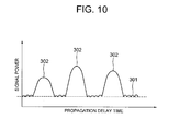
FIG. 10 shows an example where there are three paths in the delay profile. The horizontal axis inFIG. 10 represents relative propagation delay time, and the longitudinal axis represents signal powers.Reference numeral 301 inFIG. 10 indicates a noise level, and it is assumed that there exists an effective path when the signal power is at apeak position 302 for thenoise level 301. - For such paths present in the delay profile, the aforementioned finger receiver is allocated and demodulation is performed. When the allocation is done once, a measure is taken to prevent allocation of other finger receivers to the vicinity of the allocated path, i.e., a measure is taken to set a mask region to the vicinity of the path to which the finger receiver is allocated so as to prevent allocation of other finger receivers to the path to which the mask region is set.
- Reasons for taking the above-described preventing measure are as follows. That is, paths in the vicinity of the significant path in many cases are side lobes of that path, i.e., paths that are not independent of the allocated path. Thus, even if finger receivers are allocated to such paths and rake combine is performed thereon, the path diversity effect cannot be obtained. In addition, noise and interference components are superimposed on the demodulated signals, which may possibly result in deteriorating the reception qualities. Furthermore, limited resources of finger receivers are used wastefully.
- In addition to setting the aforementioned mask regions, state of the propagation paths is constantly fluctuated in the mobile telecommunications, i.e., fluctuation occurs constantly in the delay profile. In order to maintain a fine reception quality, the delay profile is updated periodically. If it becomes necessary as a result thereof, tracking processing is performed for the path whose propagation delay is fluctuated, or update processing of the allocation of the finger receivers for emerging paths and fading paths is performed. For that, as shown in
FIG. 11 , a method is employed which performs the path tracking processing and the update processing of path allocation to the finger receivers by setting a path tracking region 303 for searching fluctuation of signal power peak positions, andmask regions 304 for preventing allocation of other finger receivers to the vicinity of the path that has been allocated to a finger receiver on the delay profile. -
Patent document 1 discloses a synchronous tracking method in a spread spectrum communication system having a path search function. A delay profile measuring device, an extracting device for extracting path timing signals from the delay profile, and a path identifying device for identifying a subordinate path group and an independent path are used for the path tracking operation. The path identifying device contains a threshold value setting device that is capable of setting a threshold value, and identifies each path with the path timing signal that has a value equal to or higher than the threshold value( e.g., each path with the path timing signals within ±1-chip time length) as a subordinate path group. Patent Document 1: Japanese Unexamined Patent Publication2001-313590 - There are also following issues even if the aforementioned known method is employed. That is, in a case of the delay profile shown in
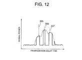
FIG. 12 , i.e., a delay profile where threepaths paths paths - When the aforementioned path tracking regions and mask regions are set for the
paths FIG. 12 , a part of the path tracking region set for a single path comes to lose the function as the path tracking region because of the mask region set for its neighboring path as shown inFIG. 12 , since the path tracking regions and the mask regions set for each of the aforementioned threepaths - Therefore, path tracking operations cannot be done in the right direction for the
path 305, in both directions for thepath 306, and in the left direction for thepath 307. When such incapability of path tracking operations occurs continuously in fluctuation of the delay profile, in particular, the reception quality deteriorates. Finally, it may result in disconnection of calls. - In
Patent Document 1, for identifying whether the paths in the delay profile are subordinate path group or independent path, it is judged whether the paths are the subordinate group or not only depending on the presence of the path timing signals but no other factors are considered for grouping the paths. That is, it is not designed to perform grouping of the paths other than the aforementioned manner. - The present invention is designed in view of the foregoing circumstances, and it is an object of the present invention to provide a path tracking method and a receiver which are used in spread spectrum communications for improving the path tracking performance for a plurality of multipaths.
- In order to overcome the foregoing issues, a receiving mechanism in a mobile communication system according to the present invention includes: a path tracking processing function of detecting signal power peaks from a delay profile of multipath multiplexed signals received via a plurality of propagation paths, separating/extracting each path contained in the multipaths based on propagation delay of the detected signal power peaks, allocating finger receivers to the signals of each of the separated/extracted paths for performing demodulation as well as rake combine of each demodulated signal, updating the delay profile every prescribed time interval for tracking chronological changes of the propagation paths, when a signal power peak position within a path tracking region set in advance for each path is fluctuated, estimating that the path is fluctuated, and performing tracking of the fluctuated path; and a mask region setting function of setting mask regions for preventing other finger receivers than the reception finger receivers to the path from being allocated to the vicinity of the path when performing the path tracking processing, wherein, when the finger receivers are allocated to each of the paths of the multipaths in which each of the paths is close to each other in terms of time, each of the constituent paths is put into a group, priority orders are set for each of the constituent paths within the group for performing path tracking operations, and path tracking processing is performed according to the priority orders.
- For the path tracking processing performed according to the priority orders, it is desirable to set the path tracking region and the mask regions for each path.
- For the path tracking processing performed according to the priority orders, the path tracking region may be set for each path to perform a tracking operation of the path, and the mask regions may be set for the path after completing the tracking operation.
- It is desirable for the grouping processing to be performed every time the tracking operation of a single path is performed. The grouping processing may also be performed when the tracking operations of all the assumed multipaths are completed.
- Further, the grouping processing may also be performed to put each of the adjacent paths when "Td<2(Tt+Tm)" applies, provided that a propagation delay time difference of the adjacent paths is "Td", a half of time length of the path tracking region is "Tt", and time length of the mask region is "Tm".
- Furthermore, the grouping processing may also be performed to put each of the adjacent paths into a group, when the propagation delay time difference of the adjacent paths is within prescribed time that is set in advance.
- Further, the priority orders may be so set that the path having the maximum signal power within the group is given the highest priority, or may be set in order from the path having the higher signal power to the path having the lower signal power. The priority orders may be set in order of time at which separation/extraction of the paths is executed, or may be set in order of executing separation/extraction of the paths from the latest to the oldest.
- After the path tracking operation is performed by setting the path tracking region and the mask regions for the most preferential allocated path among the paths under the priority order, the path tracking operations for the remaining paths may be executed by setting the path tracking regions and the mask regions for the paths uniformly. After performing the tracking operation of the path under the priority order by setting the path tracking region and the mask regions for the path according to the priority order and resetting the path tracking region and the mask regions to the path to which the tracking operation has been done, the path tracking regions and the mask regions may be set for the remaining paths to perform the path tracking operations.
- A path tracking method of a mobile communication system according to the present invention, which: detects signal power peaks from a delay profile of multipath multiplexed signals received via a plurality of propagation paths; separates/extracts each path contained in the multipaths based on propagation delay of the detected signal power peaks; allocates finger receivers to the signals of each of the separated/extracted paths for performing demodulation as well as rake combine of each demodulated signal; updates the delay profile every prescribed time interval for tracking chronological changes of the propagation paths; when a signal power peak position within a path tracking region set in advance for each path is fluctuated, assumes that the path is fluctuated; and sets a path tracking region to the fluctuated path and sets mask regions for preventing other finger receivers than the finger receivers allocated to the path from being allocated to the vicinity of the path, wherein, when the finger receivers are allocated to each of the paths of the multipaths in which each of the paths is close to each other in terms of time, each of the constituent paths is put into a group, priority orders are set for each of the constituent paths within the group for performing path tracking operations, and path tracking processing is performed according to the priority orders.
- The path tracking processing performed according to the priority orders may be executed by setting the path tracking region and the mask regions for each path. Alternatively, the path tracking region may be set for each path to perform the tracking operation of the path, and the mask regions may be set for the path after completing the tracking operation.
- The path tracking processing may be executed after completing the tracking operations of all the assumed multipaths.
- Further, the grouping processing may also be performed to put each of the adjacent paths when "Td<2(Tt+Tm)" applies, provided that a propagation delay time difference of the adjacent paths is "Td", a half of time length of the path tracking region is "Tt", and time length of the mask region is "Tm". The grouping processing may also be performed to put each of the adjacent paths into a group, when the propagation delay time difference of the adjacent paths is within a prescribed time that is set in advance.
- Further, the priority orders are set so that the path having the maximum signal power within the group is given the highest priority. The priority orders may be set in order from the path having the higher signal power to the path having the lower signal power. The priority orders may be set in order of time at which separation/extraction of the paths is executed, or may be set in order of executing separation/extraction of the paths from the latest to the oldest.
- After the path tracking operation is performed by setting the path tracking region and the mask regions for the most preferential allocated path among the paths under the priority order, the path tracking operation for the remaining paths may be executed by setting the path tracking regions and the mask regions for the paths uniformly. After performing the tracking operation of the path under the priority order by setting the path tracking region and the mask regions for the path according to the priority order and resetting the path tracking region and the mask regions to the path to which the tracking operation has been done, the path tracking regions and the mask regions may be set for the remaining paths to perform the path tracking operations.
- With the present invention, for performing the tracking operations of the paths fluctuated in accordance with chronological changes of the propagation paths at the time of receiving multipath multiplexed signals, when finger receivers are allocated to each of the paths of the multipaths close to each other in terms of time, the paths are put into a group, priority orders for performing the tracking operations are given to each path within the group, and path tracking processing is performed according to the priority orders. Therefore, the path tracking operations can be prevented from becoming incapable because of the mask regions, so that the reception qualities can be improved.
- Exemplary embodiments of the invention will be described hereinafter by referring to the accompanying drawings.
- As a basic structure, a mobile communication system receiver according to the exemplary embodiment is a receiver which, based on a delay profile of multipath multiplexed signals to be received, separates/extracts each path contained in multipaths, demodulates received signals by each of the separated paths, and performs rake combine on the demodulated signals. The receiver separates/extracts each path contained in the multipaths and allocates demodulation finger receivers to the separated/extracted paths, and sets priority orders for paths in an adjacent path group having small propagation delay time separated/extracted from the multipaths to eliminate interference generated between adjacent paths according to the priority orders, and performs path tracking processing. Next, the exemplary embodiments will be described in details by using a specific example.
- A case of applying the receiver of the mobile communication system according to the exemplary embodiments to a DS-CDMA mode receiver will be described as a first exemplary embodiment. As described above, a
CDMA receiver 1 according to the first exemplary embodiment puts the paths of multipath multiplexed signals received via a plurality of propagation paths into a group when path tracking regions and mask regions set for those paths overlap with each other, gives priority orders to each path within the groups, and performs tracking operations of each path according to the priority orders. As shown inFIG. 1 , theCDMA receiver 1 has a delayprofile creation unit 12, apath allocation unit 14, a plurality of numbers offinger reception units 16, and arake combine unit 18. Although not shown, the CDMA receiver has a radio reception unit and an A/D conversion unit. Base band digital signals that are digital signals converted from analog signals in the A/D conversion unit are inputted to the delayprofile creation unit 12. - The radio reception unit down-converts received signals from a radio frequency and also converts those to base band analog (I/Q) signals by phase demodulation. The A/D conversion unit converts the base band analog signals to base band digital signals, and outputs the base band digital signals to the delay
profile creation unit 12. The delayprofile creation unit 12 creates a delay profile (for example, the delay profile shown inFIG. 4 ) based on the base band digital signals. The delayprofile creation unit 12 updates the delay profile every time the base band digital signal is inputted from the A-D conversion unit. - The
path allocation unit 14 separates/extracts paths contained in the multipaths based on the delay profile outputted from the delayprofile creation unit 12, and allocates the separated/extracted paths to thefinger reception units 16. Thepath allocation unit 14 sets the priority orders for the paths of an adjacent path group having small propagation time difference separated from the multipaths to eliminate interference between the adjacent paths according to the priority orders, and performs path tracking operations. Further, thepath allocation unit 14 assumes each peak of the signal power values in the delay profile as the paths and, among the paths, allocates the path that is assumed to be effective (equal to or more than the threshold value) to eachfinger reception unit 16. Thepath allocation unit 14 performs the path tracking operation based on the updated delay profile every time the delayprofile creation unit 12 updates the delay profile. That is, thepath allocation unit 14 detects whether the peak of signal power value of each path assumed before update is fluctuated or not, and updates allocation of the finger reception unit for the path based on the detection result. - Specifically, the
path allocation unit 14 is configured with agrouping unit 22, a judgingunit 24, and a path trackingprocessing unit 26, as shown inFIG. 2 . - The
grouping unit 22 puts the paths into a single path and paths of an adjacent path group when separating/extracting each path from the multipaths based on the delay profile, and allocates thefinger reception unit 16 to each of the grouped paths. That is, when allocating thefinger reception units 16, thegrouping unit 22 puts the paths into the single path and the paths of the adjacent path group by judging whether the propagation time difference of the adjacent paths is within the set time or not. - This will be described in a concretive manner. It is assumed here that the created delay profile is the one shown in
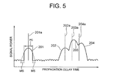
FIG. 4 . Thegrouping unit 22 calculates propagation delay time difference "Td" between afirst path 201 and a succeedingpath 202 shown inFIG. 4 , and acknowledges the paths with the propagation time difference within the set time (Td<2 (Tt+Tm)) as the paths within the adjacent path group, based on the fact that a condition "Td<2 (Tt+Tm) " applies or not. The condition "Td<2(Tt+Tm)" will be described. For a path such as thepath 201 inFIG. 5 , a path tracking region PC is set as a region for tracking a position to be the peak of the signal power value, and mask regions MS are set in side lobes of the path tracking region PC. "2Tt" indicates time length of the path tracking region PC, and "2Tm" indicates time length of the mask regions MS. Thegrouping unit 22 assumes the position where the signal power value in the delay profile becomes the peak as the position of the path, and performs aforementioned grouping processing based on the assumed result. - In the delay profile shown in
FIG. 4 , "2(Tt+Tm)<Td" applies for thepath 202 with respect to the succeedingpath 201. Thus, thegrouping unit 22 acknowledges thepath 201 as an independent path (single path). - In the delay profile shown in
FIG. 4 , thepaths paths grouping unit 22 acknowledges thepaths - The
grouping unit 22 separates thepaths paths FIG. 4 . - As a way of example, a following case will be described. In the delay profile shown in
FIG. 4 , when thegrouping unit 22 separates thepaths grouping unit 22 sets the priority orders based on the signal power values of the paths, eliminates the interference between the adjacent paths according to the priority orders, and separates the paths into individual paths. - In the delay profile shown in
FIG. 4 , among thepaths second path 203 received with propagation delay time with respect to thepath 202 has the highest signal power value. The path having the second highest signal power value following the signal power value of thepath 203 is thepath 204, and the path having the lowest signal power value is thepath 202. Thus, thegrouping unit 22 separates thepaths path 203 > signal power value of thepath 204 > signal power value of the path 202). - Through the above-described processing, the
grouping unit 22 allocates thepath 201 as the independent path and thepaths finger reception units 16. When the signal power values of thepath 201 as the independent path and thepaths grouping unit 22 stops allocations of thepaths finger reception units 16. - The judging
unit 24 receives information from thegrouping unit 22, and judges each of thepaths grouping unit 22 to find out whether thepath 201 is the independent path or not, and whether thepaths unit 24 outputs the judgment result to the path trackingprocessing unit 26. - The path tracking
processing unit 26 performs path tracking processing for thepath 201 as the independent path and thepaths unit 24. It is to be understood that thepath 201 is the independent path and thepaths unit 24. - As shown in
FIG. 5 , the path trackingprocessing unit 26 sets the path tracking region PC for thepath 201, sets the mask regions MS in the side lobes thereof, and performs path tracking processing for thepath 201. Specifically, the path trackingprocessing unit 26 performs processing to judge whether or not there is time shift generated in the peak position of the signal power value of thepath 201 before and after updating, based on the information with which thegrouping unit 22 assumes the peak position in the delay profile as thepath 201 and the information with which thegrouping unit 22 assumes the peak position in the updated delay profile as thepath 201. InFIG. 5 , the regions with dotted lines in thepath 201 are the mask regions MS. - Next, described is a case where the path tracking
processing unit 26 performs the path tracking processing for thepaths path 201. As shown inFIG. 5 - FIG. 9 , the path trackingprocessing unit 26 sets the priority orders to thepaths paths paths
Specifically, the path trackingprocessing unit 26 performs the processing to judge whether or not there is time shift generated in the peak positions of the signal power value of thepaths grouping unit 22 assumes the peak positions in the delay profile as thepaths grouping unit 22 assumes the peak positions in the updated delay profile as thepaths - In the delay profile shown in
FIG. 4 , the path trackingprocessing unit 26 sets the priority orders in order of thepath 203, thepath 204, and thepath 202, and performs the path tracking processing for thepath 203 first, then performs the path tracking processing for thepath 204, and performs the path tracking processing for thepath 202 last. - The
finger reception unit 16 performs CDMA code demodulation (despread) of the receiving signals for each path according to an instruction from thepath allocation unit 14. The rake combineunit 18 performs rake combine of the demodulated signals for each path from each of thefinger reception units 16, and outputs the CDMA demodulation signal. - In the explanations above, the CDMA receiver according to the first exemplary embodiment is built as hardware. However, it is not limited only to such a case. It may be built as software for allowing a CPU of a computer configuring the CDMA receiver to execute each of the above-described functions of the
delay profile unit 12, thepath allocation unit 14, thefinger reception unit 16, and the rake combineunit 18 based on a control program. - Next, actions of the receiver of a mobile communication system according to the exemplary embodiment will be described by referring to
FIG. 3 . - For the sake of explanations, it is to be understood that the delay
profile creation unit 12 creates the delay profile shown inFIG. 4 based on the inputted base band digital signals, and that thepath allocation unit 14 assumes, based on the delay profile shown inFIG. 4 , the fourpoints finger reception units 16 to the assumedpaths - Now, described is a case where, under the above-described state, the delay
profile creation unit 12 updates the previous delay profile, extracts each path contained in the multipaths based on the updated delay profile, performs path tracking processing for the extracted paths, and updates the allocation of thefinger reception units 16 for the paths to which the path processing is performed. - In
FIG. 4 , thepaths FIG. 4 , 201a, 202a, 203a, and 204a are the points assumed as the paths at the positions of the signal power value peaks in the delay profile before being updated. As shown inFIG. 4 , unit sampling time Tt for specifying the path tracking region for the path is set on the left and right sides with respect to the peak position of the path signal power value, and the path tracking region is set as sampling time 2Tt. Unit sampling time Tm for specifying the mask region is set on the outer sides of the path tracking region, respectively, and the mask regions are set as sampling time 2Tm. WhileFIG. 4 shows a case where the path tracking region PC (2Tt) and the mask regions MS (2Tm) are set for thepath 201, the paths tracking region (2Tt) and the mask regions MS (2Tm) are also set in the same manner for thepaths FIG. 4 , the propagation delay time difference of thepath 202 with respect to thepath 201 is propagation delay time Td. The propagation delay time difference Td also exists between thepath 202 and thepath 203 as well as between thepath 203 and thepath 204, although the lengths thereof vary. - First, the
grouping unit 22 calculates the propagation delay time difference Td between thefirst path 201 and the succeedingpath 202 shown inFIG. 4 (step S1 ofFIG. 3 ). - The
grouping unit 22 judges whether or not the condition "Td<2(Tt+Tm)" applies, based on the calculated propagation delay time difference Td (step S2 ofFIG. 3 ). - In the delay profile shown in
FIG. 4 , "2(Tt+Tm)>Td" applies for thepath 202 with respect to the succeedingpath 201. Thegrouping unit 22 acknowledges thepath 201 as an independent path (step S2 ofFIG. 3 ; N). - In the delay profile shown in
FIG. 4 , thepath 202, thepath 203, and thepath 204 have very small propagation delay time differences and are propagated closely, so that "2(Tt+Tm)>Td" does not apply for thepaths grouping unit 22 acknowledges thepaths FIG. 3 ; Y). - When the above-described processing is not performed for all the adjacent paths (step S5 of
FIG. 3 ; N), thegrouping unit 22 shifts the processing to step S1. In the meantime, when the above-described processing is performed for all the adjacent paths (step S5 ofFIG. 3 ; Y), thegrouping unit 22 assumes the position of the signal power peak in the updated delay profile as thepath 201 based on the information with which it acknowledges thepaths FIG. 4 . Similarly, thegrouping unit 22 assumes the positions of the signal power peaks in the updated delay profile as thepaths adjacent paths - The
grouping unit 22 considers thesecond path 203 received with propagation delay time with respect to thepath 202 as the path having the highest signal power value, considers thepath 204 as the path having the second highest signal power value following the signal power value of thepath 203, and considers thepath 202 as the path having the lowest signal power value. Based on the signal power values of the paths, thegrouping unit 22 separates thepaths - Through the above-described processing, the
grouping unit 22 allocates thefinger reception units 16 to thepath 201 as the independent path and thepaths - Next, the judging
unit 24 receives the information from thegrouping unit 22, and judges whether thepath 201 is the independent path or not and whether thepaths paths FIG. 3 ). The judgingunit 24 outputs the judgment result to the path trackingprocessing unit 26. - The path tracking
processing unit 26 performs the path tracking processing described below separately for a case where the path is the single path (independent path) and for a case where the paths are the paths of the adjacent path group based on the information outputted from the judgingunit 24. - When the
path 201 is the single path (step S6 ofFIG. 3 ; Y), the path trackingprocessing unit 26 sets the path tracking region PC for thepath 201 and sets the mask regions MS in the side lobes as inFIG. 5 , and performs the path tracking processing for thepath 201, i.e., performs processing for searching the highest point of the signal power value in thepath 201. That is, the path trackingprocessing unit 26 assumes that the path is fluctuated when there is fluctuation in thepeak 201a of the signal power value within the path tracking region PC, and have the path track the peak position of the signal power value (step S7 ofFIG. 3 ). In the case ofFIG. 5 , the peak of thepath 201 is consistent with the peak position of the signal power value. Thus, the path trackingprocessing unit 26 ends the path tracking processing for the path 201 (step S7 ofFIG. 3 ). - Next, the path tracking
processing unit 26 performs the path tracking processing in a manner described below for thepaths adjacent paths FIG. 3 ; N). - As shown in
FIG. 5 - FIG. 9 , the path trackingprocessing unit 26 sets the priority orders of thepaths paths paths paths - That is, as shown in
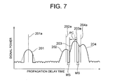
FIG. 4 , the path trackingprocessing unit 26 selects thepath 203 that has the highest signal power value (step S8 ofFIG. 3 ). Then, as shown inFIG. 6 , the path trackingprocessing unit 26 sets the path tracking region PC to thepath 203, sets the mask regions MS to the side lobes, and performs the path tracking processing for thepath 203. As shown inFIG. 6 , the peak position of the signal power value within the path tracking region PC is shifted to the right side from thepeak 203a. Thus, the path trackingprocessing unit 26 assumes that thepath 203 is fluctuated, and makes the peak of thepath 203 follow thepeak 203a to the right side thereof as shown inFIG. 7 (step S9 ofFIG. 3 ). - Then, the path tracking
processing unit 26 performs the path tracking processing for the remaining paths of the above-described adjacent path group such as each of thepaths FIG. 4 (step S10 ofFIG. 3 ). That is, as shown inFIG. 8 , the path trackingprocessing unit 26 performs the path tracking processing for thepath 204 by setting the path tracking region PC and the mask regions MS to thepath 204. InFIG. 8 , among the waveform of thepath 204, the area shown with a solid line is the path tracking region PC, and the areas shown with dotted lines are the mask regions MS. As can be seen fromFIG. 8 , the peak position of the signal power value within the path tracking region PC is shifted to the right side from thepeak 204a. Thus, the path trackingprocessing unit 26 assumes that thepath 204 is fluctuated, and makes the peak of thepath 204 follow thepeak 204a to the right side thereof as shown inFIG. 8 (step S10 ofFIG. 3 ). In this case, the path tracking region PC and the mask regions MS for thepath 203 that is adjacent to thepath 204 are not set. Thus, the mask regions in the side lobes of thepath 203 and thepath 204 do not overlap with each other, i.e., occurs no interference. - As shown in
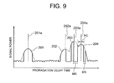
FIG. 8 , there is time shift in the peak position of the signal power value of thepath 204. Thus, the path trackingprocessing unit 26 performs the path tracking processing as inFIG. 9 (step S10 ofFIG. 3 ). - The path tracking
processing unit 26 performs the same processing as that of thepath 204 for thepath 202 as well (step S10 ofFIG. 3 ). - The path tracking
processing unit 26 judges whether or not the processing from step S6 to step S10 is completed for all the allocated paths (step S11 ofFIG. 3 ). When not completed (N in step S11 ofFIG. 3 ), the path trackingprocessing unit 26 repeatedly executes the processing from step S6 to step S10. Inversely, when the path tracking processing has been completed for all the allocated paths (Y in step S11 ofFIG. 3 ), as shown inFIG. 9 , the path trackingprocessing unit 26 ends a series of processing for the current updating operation of the paths (step S12 ofFIG. 3 ). - After the series of processing (after a prescribed time period), an updating operation of the next path allocation, i.e., searching of new paths and canceling of allocation to the fading paths, is also performed as in the conventional case. The updating operation of the path allocation is not the substance of this exemplary embodiment, so that explanations thereof are omitted.
- In the first exemplary embodiment, it is judged to find out whether or not the path tracking regions and the mask regions set for each of the allocated paths overlap with each other before setting the path tracking regions and the mask regions for the allocated paths. Further, the path tracking region and the mask regions are set preferentially for the path that has the highest signal power among the paths in the overlapping regions, and the path tracking processing is performed. Therefore, it is possible to avoid having a part of the path tracking region of that path to be set within the mask regions that are set for another allocated path. In other words, it is not to be lost by the mask region set for another allocated path. Therefore, it is possible to prevent the path tracking ability becoming incapable. This makes it possible to continuously maintain the reception quality.
- In the first exemplary embodiment, the priority orders when performing the path tracking operations for the paths of the adj acent path group are set based on the signal power values. However, it is not limited only to such a case. The priority orders may be set based on the time orders at which the paths of the adjacent path group are separated/extracted. The same effects as those of the first exemplary embodiment can be obtained also with this structure. Further, for grouping the paths, it is possible to put the paths into a group every time the path tracking processing is performed for a single path or at the point where the path tracking processing for all the assumed multipaths is completed.
- In this exemplary embodiment, the priority orders when performing the path tracking operations for the paths set as the adjacent path group may be set based on the orders of allocating the finger reception units to the paths. The same effects as those of the first exemplary embodiment can be obtained also with this structure.
- In this exemplary embodiment, after the path tracking operation is performed by setting the path tracking region and the mask regions for the most preferential allocated path among the adjacent path group allocated by the path allocation unit, if the mask regions set for the remaining paths do not interfere with each other, the path tracking operations for the allocated paths within the adjacent path group may be executed by setting the path tracking regions and the mask regions for the remaining paths uniformly. With this structure, the path tracking processing for the remaining paths can be executed in parallel, which is advantageous in respect that the path tracking processing can be performed promptly.
- In this exemplary embodiment, every time the path tracking processing for a single allocated path is completed, it is judged whether or not the allocated paths overlap with each other, and the path tracking processing may be performed based on the judgment result. This structure is advantageous in respect that it is possible to surely prevent interference of the mask regions of the paths that are contained in the adjacent path group.
- In this exemplary embodiment, the path tracking processing according to the priority orders may be performed as follows. That is, the path tracking region may be set for the highest priority path for performing the path tracking operation, the mask regions may be set for the highest priority path when the tracking operation is completed, and the path tracking operation may be performed for the paths after the highest priority path by setting the path tracking region and the mask regions successively.
- The present invention can be applied not only to the CDMA receiver but also to receivers of other forms which receive multipath multiplexed signals other than spread spectrum signals received via a plurality of propagation paths in a spread spectrum mode.
-
-
FIG. 1 is a block diagram showing an electrical structure of a CDMA receiver according to a first exemplary embodiment of the invention; -
FIG. 2 is a block diagram showing a specific structure of a path allocation unit of the CDMA receiver according to the first exemplary embodiment of the invention; -
FIG. 3 is a flowchart for describing actions of the path allocation unit of the CDMA receiver according to the first exemplary embodiment of the invention; -
FIG. 4 is an illustration showing an example of paths allocated by the path allocation unit of the CDMA receiver according to the first exemplary embodiment of the invention; -
FIG. 5 is an illustration showing a setting example of path tracking regions and mask regions set by the path allocation unit of the CDMA receiver according to the first exemplary embodiment of the invention; -
FIG. 6 is an illustration showing a setting example of path tracking regions and mask regions set by the path allocation unit of the CDMA receiver according to the first exemplary embodiment of the invention for an allocated path that has the maximum signal power; -
FIG. 7 is an illustration showing an example of a state after completing a path tracking operation performed by the path allocation unit of the CDMA receiver according to the first exemplary embodiment of the invention; -
FIG. 8 is an illustration showing an example of mask regions set by the path allocation unit of the CDMA receiver according to the first exemplary embodiment of the invention; -
FIG. 9 is an illustration showing another example of the state after completing the path tracking operation performed by the path allocation unit of the CDMA receiver according to the first exemplary embodiment of the invention; -
FIG. 10 is an illustration showing an example of a delay profile created by a conventional CDMA-mode receiver; -
FIG. 11 is an illustration showing path tracking regions and mask regions set for the paths in a delay profile with a conventional technique; and -
FIG. 12 is an illustration for describing a technical problem that occurs when setting path tracking regions and mask regions for each of a plurality of multipaths in the delay profile with the conventional technique. -
- 1
- CDMA receiver
- 12
- Delay profile creation unit
- 14
- Path allocation unit
- 22
- Grouping unit
- 24
- Judging unit
- 26
- Path tracking processing unit
Claims (14)
- A mobile communication system receiver which, based on a delay profile of multipath multiplexed signals to be received, separates/extracts each path contained in multipaths, demodulates received signals by each of the separated paths, and performs rake combine on the demodulated signals, the receiver comprising a path allocation means for separating/extracting each path contained in the multipaths and allocating the separated/extracted paths to demodulation finger receivers, wherein
the path allocation means sets priority orders for paths in an adjacent path group having small propagation delay time separated from the multipaths to eliminate interference generated between adjacent paths according to the priority orders, and performs path tracking processing. - The receiver as claimed in claim 1, wherein the path allocation means executes path tracking by setting a path tracking region and mask regions for each path according to the priority orders.
- The receiver as claimed in claim 1, wherein, when propagation delay time difference of the adjacent paths is within the set time, the path allocation means acknowledges the paths as the paths of the adjacent path group.
- The receiver as claimed in claim 3, wherein the path allocation means acknowledges a path as the path of the adj acent path group when "Td<2(Tt+Tm)" applies, provided that a propagation delay time difference of the adjacent paths is "Td", a half of time length of the path tracking region is "Tt", and time length of the mask region is "Tm".
- The receiver as claimed in claim 1, wherein the path allocation means sets the priority orders based on signal power values of the paths that are contained in the adjacent path group.
- The receiver as claimed in claim 1, wherein the path allocation means sets the priority orders based on orders of time at which the paths of the adjacent path group are separated/extracted.
- A path tracking method of a mobile communication system using a mobile communication system receiver which, based on a delay profile of multipath multiplexed signals to be received, separates/extracts each path contained in multipaths, demodulates received signals by each of the separated paths, and performs rake combine on the demodulated signals, wherein:each path contained in the multipaths is separated/extracted and the separated/extracted paths are allocated to demodulation finger receivers; andpriority orders are set for paths in an adjacent path group having small propagation delay time separated/extracted from the multipaths to eliminate interference generated between adjacent paths according to the priority orders, and path tracking processing is performed.
- The path tracking method of the mobile communication system as claimed in claim 7, wherein a path tracking operation is performed by setting a path tracking region and mask regions for each path according to the priority orders.
- The path tracking method of the mobile communication system as claimed in claim 7, wherein, when propagation delay time difference of the adjacent paths is within the set time, the paths are acknowledged as the paths of the adjacent path group.
- The path tracking method of the mobile communication system as claimed in claim 9, wherein a path is acknowledged as the path of the adjacent path group when "Td<2(Tt+Tm)" applies, provided that a propagation delay time difference of the adjacent paths is "Td", a half of time length of the path tracking region is "Tt", and time length of the mask region is "Tm".
- The path tracking method of the mobile communication system as claimed in claim 7, wherein the priority orders are set based on signal power values of the paths that are contained in the adjacent path group.
- The path tracking method of the mobile communication system as claimed in claim 7, wherein the priority orders are set based on orders of time at which the paths of the adjacent path group are separated/extracted.
- A control program for allowing a computer that configures a mobile communication system which, based on a delay profile of multipath multiplexed signals to be received, separates/extracts each path contained in multipaths, demodulates received signals by each of the separated paths, and performs rake combine on the demodulated signals, to execute:a function of separating/extracting each path contained in the multipaths and allocating the separated/extracted paths to demodulation finger receivers; anda function of setting priority orders for paths in an adjacent path group having small propagation delay time difference separated/extracted from the multipaths to eliminate interference generated between adjacent paths according to the priority orders, and performing path tracking processing.
- The control program as claimed in claim 13, which allows the computer to execute a function of performing a path tracking operation by setting a path tracking region and a mask regions for each path according to the priority orders.
Applications Claiming Priority (2)
| Application Number | Priority Date | Filing Date | Title |
|---|---|---|---|
| JP2006053582 | 2006-02-28 | ||
| PCT/JP2007/053623 WO2007099943A1 (en) | 2006-02-28 | 2007-02-27 | Mobile communication system receiver, path following method, and control program thereof |
Publications (2)
| Publication Number | Publication Date |
|---|---|
| EP1990927A1 true EP1990927A1 (en) | 2008-11-12 |
| EP1990927A4 EP1990927A4 (en) | 2012-02-08 |
Family
ID=38459047
Family Applications (1)
| Application Number | Title | Priority Date | Filing Date |
|---|---|---|---|
| EP07737425A Withdrawn EP1990927A4 (en) | 2006-02-28 | 2007-02-27 | Mobile communication system receiver, path following method, and control program thereof |
Country Status (5)
| Country | Link |
|---|---|
| US (1) | US8149898B2 (en) |
| EP (1) | EP1990927A4 (en) |
| JP (1) | JP4867989B2 (en) |
| CN (1) | CN101395813B (en) |
| WO (1) | WO2007099943A1 (en) |
Cited By (1)
| Publication number | Priority date | Publication date | Assignee | Title |
|---|---|---|---|---|
| WO2013025134A1 (en) * | 2011-08-17 | 2013-02-21 | Telefonaktiebolaget L M Ericsson (Publ) | A receiver unit and method for suppressing interference in a multipath radio signal |
Families Citing this family (2)
| Publication number | Priority date | Publication date | Assignee | Title |
|---|---|---|---|---|
| US8798214B2 (en) * | 2007-11-14 | 2014-08-05 | Qualcomm Incorporated | Minimum finger low-power demodulator for wireless communication |
| CN102142860B (en) * | 2010-01-29 | 2014-01-29 | 上海摩波彼克半导体有限公司 | Method for multi-path combining control of RAKE receiver in third-generation mobile communication system |
Family Cites Families (10)
| Publication number | Priority date | Publication date | Assignee | Title |
|---|---|---|---|---|
| JP2000031889A (en) * | 1998-07-13 | 2000-01-28 | Hitachi Ltd | Mobile communication terminal of spread spectrum communication system |
| JP3031354B1 (en) * | 1998-09-30 | 2000-04-10 | 日本電気株式会社 | CDMA receiver, multipath finger assignment method thereof, and recording medium recording control program therefor |
| JP3387471B2 (en) | 2000-02-14 | 2003-03-17 | 日本電気株式会社 | Spread spectrum communication system receiver and path search method for spread spectrum communication |
| US7184457B2 (en) * | 2000-02-28 | 2007-02-27 | Texas Instruments Incorporated | Spread spectrum path estimation |
| JP3633847B2 (en) * | 2000-04-27 | 2005-03-30 | シャープ株式会社 | Synchronous tracking method |
| JP3565269B2 (en) * | 2001-08-22 | 2004-09-15 | 日本電気株式会社 | CDMA receiver, path search method, and program |
| KR100547737B1 (en) * | 2003-06-10 | 2006-01-31 | 삼성전자주식회사 | Rake receiver and method in direct sequence code division multiple access mobile communication system |
| JP4309193B2 (en) * | 2003-08-14 | 2009-08-05 | 株式会社日立国際電気 | Path detection method |
| DE10345959B4 (en) * | 2003-10-02 | 2005-12-15 | Infineon Technologies Ag | Operational situation-dependent identification and selection of the transmission paths for the establishment of rake fingers of Rake receiver units in mobile communication terminals |
| US7310365B2 (en) * | 2003-10-31 | 2007-12-18 | Texas Instruments Incorporated | Group decision rule in code tracking using a delay lock loop (DLL) |
-
2007
- 2007-02-27 JP JP2008502789A patent/JP4867989B2/en not_active Expired - Fee Related
- 2007-02-27 WO PCT/JP2007/053623 patent/WO2007099943A1/en not_active Ceased
- 2007-02-27 CN CN200780007165.XA patent/CN101395813B/en not_active Expired - Fee Related
- 2007-02-27 US US12/280,284 patent/US8149898B2/en not_active Expired - Fee Related
- 2007-02-27 EP EP07737425A patent/EP1990927A4/en not_active Withdrawn
Cited By (2)
| Publication number | Priority date | Publication date | Assignee | Title |
|---|---|---|---|---|
| WO2013025134A1 (en) * | 2011-08-17 | 2013-02-21 | Telefonaktiebolaget L M Ericsson (Publ) | A receiver unit and method for suppressing interference in a multipath radio signal |
| US8971386B2 (en) | 2011-08-17 | 2015-03-03 | Telefonaktiebolaget L M Ericsson (Publ) | Receiver unit and method for suppressing interference in a multipath radio signal |
Also Published As
| Publication number | Publication date |
|---|---|
| JPWO2007099943A1 (en) | 2009-07-16 |
| JP4867989B2 (en) | 2012-02-01 |
| US8149898B2 (en) | 2012-04-03 |
| WO2007099943A1 (en) | 2007-09-07 |
| EP1990927A4 (en) | 2012-02-08 |
| CN101395813A (en) | 2009-03-25 |
| CN101395813B (en) | 2013-04-03 |
| US20100232477A1 (en) | 2010-09-16 |
Similar Documents
| Publication | Publication Date | Title |
|---|---|---|
| AU751260B2 (en) | Method of providing hysteresis in detection of path timing by multiplying delay profile by weighting coefficient | |
| EP0924868B1 (en) | Cell search method and mobile station apparatus | |
| US6813309B1 (en) | CDMA receiving method and circuit | |
| EP0940926B1 (en) | Spectrum spreading communication system using single spreading code | |
| US6895036B2 (en) | Apparatus and method for sub-chip offset correlation in spread-spectrum communication systems | |
| KR19990067991A (en) | Finger assignment in a CDMA rake receiver | |
| WO2005020458A1 (en) | Positioning of a path searcher window in a cdma receiver | |
| US6959070B2 (en) | Radio base station apparatus and radio communication method | |
| JP2002164815A (en) | Multi-path detecting method and its circuit of cdma receiving set | |
| JP4434202B2 (en) | Cell search method for wireless communication system | |
| US8149898B2 (en) | Mobile communication system receiver, path tracking method, and control program thereof | |
| KR100453811B1 (en) | Apparatus for searching multipath in spread spectrum cummunicatios and method thereof | |
| US7088699B1 (en) | Cellular receiver and reception method | |
| KR100608123B1 (en) | Cdma reception apparatus and base station thereof | |
| KR20010031524A (en) | Synchronizing device and synchronizing method | |
| JP3748351B2 (en) | CDMA radio transmitter and CDMA radio receiver | |
| US7724808B2 (en) | Efficient delay profile computation with receive diversity | |
| US20080151969A1 (en) | Efficient Delay Profile Computation with Receive Diversity | |
| EP1154584A1 (en) | Mobile station and method for allocating rake fingers and tracking devices | |
| WO2005032181A1 (en) | Dynamic allocation of resources | |
| HK1074540B (en) | Cdma reception apparatus and base station thereof |
Legal Events
| Date | Code | Title | Description |
|---|---|---|---|
| PUAI | Public reference made under article 153(3) epc to a published international application that has entered the european phase |
Free format text: ORIGINAL CODE: 0009012 |
|
| 17P | Request for examination filed |
Effective date: 20080821 |
|
| AK | Designated contracting states |
Kind code of ref document: A1 Designated state(s): DE FR GB IT |
|
| RBV | Designated contracting states (corrected) |
Designated state(s): DE FR GB IT |
|
| A4 | Supplementary search report drawn up and despatched |
Effective date: 20120105 |
|
| RIC1 | Information provided on ipc code assigned before grant |
Ipc: H04B 1/7113 20110101AFI20111230BHEP Ipc: H04B 1/7115 20110101ALI20111230BHEP Ipc: H04B 1/7117 20110101ALI20111230BHEP |
|
| DAX | Request for extension of the european patent (deleted) | ||
| RAP1 | Party data changed (applicant data changed or rights of an application transferred) |
Owner name: LENOVO INNOVATIONS LIMITED (HONG KONG) |
|
| STAA | Information on the status of an ep patent application or granted ep patent |
Free format text: STATUS: THE APPLICATION HAS BEEN WITHDRAWN |
|
| 18W | Application withdrawn |
Effective date: 20150225 |