EP1154584A1 - Mobile station and method for allocating rake fingers and tracking devices - Google Patents
Mobile station and method for allocating rake fingers and tracking devices Download PDFInfo
- Publication number
- EP1154584A1 EP1154584A1 EP00110026A EP00110026A EP1154584A1 EP 1154584 A1 EP1154584 A1 EP 1154584A1 EP 00110026 A EP00110026 A EP 00110026A EP 00110026 A EP00110026 A EP 00110026A EP 1154584 A1 EP1154584 A1 EP 1154584A1
- Authority
- EP
- European Patent Office
- Prior art keywords
- finger
- rake
- tracking
- early
- late
- Prior art date
- Legal status (The legal status is an assumption and is not a legal conclusion. Google has not performed a legal analysis and makes no representation as to the accuracy of the status listed.)
- Withdrawn
Links
- 238000000034 method Methods 0.000 title claims abstract description 39
- 230000007246 mechanism Effects 0.000 claims abstract description 44
- 230000004044 response Effects 0.000 claims abstract description 7
- 238000010295 mobile communication Methods 0.000 claims description 18
- 230000001413 cellular effect Effects 0.000 claims description 2
- 230000001934 delay Effects 0.000 claims description 2
- 238000004088 simulation Methods 0.000 claims 1
- 238000010586 diagram Methods 0.000 description 6
- 238000001514 detection method Methods 0.000 description 5
- 238000004891 communication Methods 0.000 description 3
- 230000003247 decreasing effect Effects 0.000 description 2
- 238000012986 modification Methods 0.000 description 2
- 230000004048 modification Effects 0.000 description 2
- 238000012544 monitoring process Methods 0.000 description 2
- 238000001228 spectrum Methods 0.000 description 2
- 230000003044 adaptive effect Effects 0.000 description 1
Images


Classifications
-
- H—ELECTRICITY
- H04—ELECTRIC COMMUNICATION TECHNIQUE
- H04B—TRANSMISSION
- H04B1/00—Details of transmission systems, not covered by a single one of groups H04B3/00 - H04B13/00; Details of transmission systems not characterised by the medium used for transmission
- H04B1/69—Spread spectrum techniques
- H04B1/707—Spread spectrum techniques using direct sequence modulation
- H04B1/7073—Synchronisation aspects
- H04B1/7085—Synchronisation aspects using a code tracking loop, e.g. a delay-locked loop
-
- H—ELECTRICITY
- H04—ELECTRIC COMMUNICATION TECHNIQUE
- H04B—TRANSMISSION
- H04B1/00—Details of transmission systems, not covered by a single one of groups H04B3/00 - H04B13/00; Details of transmission systems not characterised by the medium used for transmission
- H04B1/69—Spread spectrum techniques
- H04B1/707—Spread spectrum techniques using direct sequence modulation
- H04B1/7097—Interference-related aspects
- H04B1/711—Interference-related aspects the interference being multi-path interference
- H04B1/7115—Constructive combining of multi-path signals, i.e. RAKE receivers
- H04B1/7117—Selection, re-selection, allocation or re-allocation of paths to fingers, e.g. timing offset control of allocated fingers
-
- H—ELECTRICITY
- H04—ELECTRIC COMMUNICATION TECHNIQUE
- H04B—TRANSMISSION
- H04B1/00—Details of transmission systems, not covered by a single one of groups H04B3/00 - H04B13/00; Details of transmission systems not characterised by the medium used for transmission
- H04B1/69—Spread spectrum techniques
- H04B1/707—Spread spectrum techniques using direct sequence modulation
- H04B1/7097—Interference-related aspects
- H04B1/711—Interference-related aspects the interference being multi-path interference
- H04B1/7115—Constructive combining of multi-path signals, i.e. RAKE receivers
Definitions
- the present invention relates to mobile communication systems in general, and, more specifically, to a mobile station and method for allocating rake fingers for mobile communication systems, in particular in Code Division Multiple Access (CDMA) mobile systems, with high chip rates.
- CDMA Code Division Multiple Access
- a mobile station, or terminal, in particular a Code Division Multiple Access system, may be allocated to a base station.
- the CDMA mobile station When the CDMA mobile station is allocated to the base station, the CDMA mobile station will look to receive groups of multi-path components. See Viterbi, Andrew, Principles of Spread Spectrum Communications, Addison-Wesley Publishing Company.
- a known receiver architecture for CDMA mobile systems is the rake receiver. See Price, R. et al., "A Communication Technique for Multipath Channels," Proceedings of the IRE, 1958, vol. 46, pp. 555-570.
- a rake receiver consists of a bank of correlation-type receivers or correlators. Each correlator of the bank of correlators is used to detect a separate multi-path component, the correlator detecting the stronger multi-path components. Once demodulation or detection occurs, the multi-path component can be termed a multi-path demodulator or multi-path components demodulated.
- each multi-path demodulator is termed a finger or a rake finger.
- each of the decorrelated multi-paths is combined into one signal before detection. The maximal ratio combining technique is optimum combining.
- a mobile station, or terminal, of a mobile communications network must optimally combine signals into one output signal before detection while accounting for the signals' relative delays, amplitudes and phases.
- a known rake receiver used a fixed number of rake fingers, each rake finger being separated by a constant interval of T C seconds, where T C equaled the chip interval.
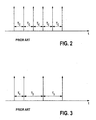
- This finger allocation method is known to work well for low bandwidths in some radio propagation environments for a simple link. See Figure 2.
- a schematic shows prior art rake receiver behavior when the rake finger allocation method uses a fixed number of rake fingers being separated by a constant interval of T C .
- rake receiver method was more adaptive in mobile communications environments. This method searches for each individual multi-path component and then allocates a rake finger having a tracking mechanism to each individual multi-path component. See Figure 3. See also Glisic et al., Spread Spectrum CDMA Systems for Wireless Communications, Artech House Publishers, 1997.
- a schematic shows prior art rake receiver behavior when the rake finger allocation method involves a search for each individual multi-path component.
- This search for the multi-path component may cause a variation in the time intervals [T 1 , T 2 , T 3 ] between the rake fingers. That is, [T 1 ], [T 2 ], and [T 3 ] may indeed not equal each other.
- each individual multi-path component is allocated a rake finger having a tracking mechanism.
- This finger allocation method is known to work well with mobile communication and relatively low chip rates, e.g., on the order of 1 Mcps.
- the known rake receiver methods and devices do not promote a finger allocation scheme that works well for mobile communication systems with high chip rates.
- the known methods in particular the first known method described above, requires a high number of rake fingers in order to capture all of the power from a time dispersive channel or from a soft handover system in a mobile communication environment. That is, the chip rate of third generation mobile communication systems, such as Universal Mobile Telephone System (UMTS), is so high that oftentimes more than one rake finger is necessary to capture the energy from one multi-path component on a radio channel.
- UMTS Universal Mobile Telephone System
- Such an increase of possibly double or more rake fingers necessary to capture the energy provides an unwanted high cost associated with the multiple number of tracking devices as well as the power and search times for detecting new multi-path components.
- the present invention provides a method and a device implementing optimal rake finger allocation, particularly for use in third generation mobile communication systems.
- the third generation mobile communication systems include Wideband Code Division Multiple Access (WCDMA) mobile communication systems.
- WCDMA Wideband Code Division Multiple Access
- the present invention also provides a method for rake finger allocation for a rake receiver, characterized in that a received channel impulse response is split into at least one bin; and a plurality of rake fingers and a tracking, or searching, mechanism is assigned to each of the at least one bin.
- the present invention provides that the tracking mechanism can serve as at least one rake finger as well.
- the present invention further provides that the method may be used in a Wideband Code Division Multiple Access mobile communication receiver system.
- the present invention also provides a method for rake finger allocation for a rake receiver, characterized in that a received channel impulse response is split into a first bin and a second bin; a first plurality of rake fingers is assigned to the first bin; a first tracking mechanism is assigned to the first bin; a second plurality of rake fingers is assigned to the second bin; and a second tracking mechanism is assigned to the second bin, where both the first and the second tracking mechanisms can also serve as rake fingers.
- the present invention also provides a mobile station for a cellular mobile communications network, the mobile station including a rake receiver having a plurality of rake fingers, the mobile station operating in a Code Division Multiple Access system, characterized in that the plurality of rake fingers are allocated to a code phase or impulse or signal. Further, a tracking mechanism having an early tracking finger and a late tracking finger is allocated to the code phase and the rake finger. According to the present invention, the early and late tracking fingers can serve as rake fingers and as tracking fingers.
- the present invention provides that the accuracy of the rake finger demodulation power is increased and that bit error probability is decreased due to the use of the tracking mechanism or tracking finger for use also as a rake finger.
- the present invention provides an increased demodulation range because the tracking mechanism or finger can also be used as a rake finger, thus increasing the time span covered by a rake finger and its accompanying tracking fingers.
- a rake finger according to the present invention can cover a time span of about T c where T c is the chip period.
- a rake finger and its accompanying tracking fingers according to the present invention may be able to cover a time span of about 2T c or more.
- the present invention provides that the overhead expense of tracking mechanisms is decreased because each rake finger or rake finger group is increased in the number of rake fingers because any tracking mechanisms assigned to the rake finger group may also serve as a rake finger.
- the present invention also provides an increased probability of finding multi-path components from a radio channel. This increased probability of finding multi-path components can effectuate an increase in demodulated power and thereby an increase in performance.
- UMT Universal Mobile Telephone System/Frequency Division Duplex
- 3GPP Third Generation Partnership Project
- a UMTS/FDD mobile terminal receives, decodes, codes and sends messages in a Code Division Multiple Access (CDMA) environment.
- Reception in a UMTS mobile terminal can be performed using a rake receiver having multiple fingers which may be allocated in groups to receive disparate signals simultaneously.
- the fingers can be allocated in groups and assigned a tracking mechanism or one early and one late tracking finger for finding multi-path components from the transmitting source of a radio signal and for use as a rake finger.
- a rake receiver consists of a bank of correlators [1]. Each correlator of the bank of correlators can be used to detect a separate multi-path component [2a, 2b...2n]. The correlators tend to detect the stronger multi-path components before the weaker multi-path components.
- the multi-path components each move through a respective integrator [3a, 3b,...3n]. From the integrators [3a, 3b, ...3n] the components are combined into one signal by a combiner [4] before detection.
- a tracking mechanism is a standard early-late gate tracker where a signal is processed through either an advance sample clock [21] or a retard sample clock [22] and then through a scale and filter [23]. The output is then categorized as an increase or a decrease of a sample clock.
- the present device or method can include dividing any received channel impulse responses into one or more bins, e.g., Bin 1 [5a] and Bin 2 [5b]. Each bin can then be assigned a set of rake fingers and one or more tracking mechanisms.
- the one or more tracking mechanisms should be capable of searching for signals, i.e., multi-path components and should be capable of serving as a rake finger.
- Each tracking mechanism has two tracking fingers, an early tracking finger and a later tracking finger.
- a UMTS mobile station [6] includes a processor [10] and a rake receiver [8] having a plurality of rake fingers [9]. Rake receiver [8] is a part of receiver system [7]. Where mobile station [6] is a multi-mode terminal having a receiver system capable of tuning between signals of two different systems, receiver system [7] may include one or more other receivers or receiver subsystems (not shown). Mobile station [6] may be a multi-mode mobile station, capable of operating, for example, in a Global System for Mobile Telecommunications (GSM) system as well as a UMTS system.
- GSM Global System for Mobile Telecommunications
- a CDMA mobile station [6] when a CDMA mobile station [6] is allocated to a base station, the CDMA mobile station [6] will look for groups of multi-path components [2a, 2b;...2n] identified by a transmitted signature sequence. For each group of multi-path components, a group of rake fingers will be assigned as, e.g., Bin 1 [5a] and Bin 2 [5b]. Each of the rake finger groups [5a, 5b] will have one or more tracking mechanisms which can also serve as rake fingers. The tracking mechanisms can be used to follow multi-path components from the radio channel and can be used as a rake finger for demodulation purposes. See Figure 1b.
- Each tracking mechanism may include two tracking fingers, that is an early tracking finger [11a] and a late tracking finger [11b]. See Fig. 6.
- the tracking mechanism may have more than one early tracking finger [1 la] and more than one late tracking finger [11b] as well.
- a tracking mechanism [11a, 11b] or a plurality of tracking mechanisms or a plurality of tracking fingers [11a, 11b], can be allocated to a rake finger [12].
- the early tracking finger [11a] is spaced by ⁇ t from the rake finger [12].
- the late tracking finger [11b] is spaced by ⁇ t from the rake finger [12].
- both tracking fingers shown [11a, 11b] can also serve as rake fingers and thus increase the accuracy and range of the rake finger demodulation effort.
- a receiver system control software in the mobile station is programmed to operate the receiver subsystem, e.g., to allocate and/or control the rake fingers, for performing the monitoring according to the present invention.
- Such programming modifications are preferably executed by processor [10] in mobile station [6] for executing radio resource management functions, or by another appropriate processor.
- the method or mobile station may be implemented via software using a microprocessor ( ⁇ P) or a digital signal processor (DSP).
- the present invention also provides that the software may control a search of hardware, the hardware including a controller, an integrator and a combiner. See Fig. 5.
- ⁇ P microprocessor
- DSP digital signal processor
- the method or mobile station device may be used in an European Telecommunications Standard Institute (ETSI) or Universal Mobile Telecommunications System (UMTS), an Association of Radio Industries and Businesses (ARIB) Wideband Code Division Multiple Access (WCDMA) system, or a Wideband Code Division Multiple Access (WCDMA) system being defined by 3 rd Generation Partnership Project (3GPP) system.
- ETSI European Telecommunications Standard Institute
- UMTS Universal Mobile Telecommunications System
- ARIB Association of Radio Industries and Businesses
- WCDMA Wideband Code Division Multiple Access
- WCDMA Wideband Code Division Multiple Access
- 3GPP 3 rd Generation Partnership Project
- the present invention may be applied to various frequency bands. Additionally, the present invention may be applied for monitoring in other types of mobile communication systems than those described herein. Also, embodiments described herein may be applied in a variety of combinations for allocating rake finger groups and their detection of multi-path components. These and other variations are intended to be part of the present invention.
Landscapes
- Engineering & Computer Science (AREA)
- Computer Networks & Wireless Communication (AREA)
- Signal Processing (AREA)
- Mobile Radio Communication Systems (AREA)
Abstract
Description
- The present invention relates to mobile communication systems in general, and, more specifically, to a mobile station and method for allocating rake fingers for mobile communication systems, in particular in Code Division Multiple Access (CDMA) mobile systems, with high chip rates.
- A mobile station, or terminal, in particular a Code Division Multiple Access system, may be allocated to a base station. When the CDMA mobile station is allocated to the base station, the CDMA mobile station will look to receive groups of multi-path components. See Viterbi, Andrew, Principles of Spread Spectrum Communications, Addison-Wesley Publishing Company.
- A known receiver architecture for CDMA mobile systems is the rake receiver. See Price, R. et al., "A Communication Technique for Multipath Channels," Proceedings of the IRE, 1958, vol. 46, pp. 555-570. A rake receiver consists of a bank of correlation-type receivers or correlators. Each correlator of the bank of correlators is used to detect a separate multi-path component, the correlator detecting the stronger multi-path components. Once demodulation or detection occurs, the multi-path component can be termed a multi-path demodulator or multi-path components demodulated. In the rake receiver, each multi-path demodulator is termed a finger or a rake finger. In the rake receiver, each of the decorrelated multi-paths is combined into one signal before detection. The maximal ratio combining technique is optimum combining.
- A mobile station, or terminal, of a mobile communications network must optimally combine signals into one output signal before detection while accounting for the signals' relative delays, amplitudes and phases.
- A known rake receiver used a fixed number of rake fingers, each rake finger being separated by a constant interval of TC seconds, where TC equaled the chip interval. This finger allocation method is known to work well for low bandwidths in some radio propagation environments for a simple link. See Figure 2. Referring to Figure 2, a schematic shows prior art rake receiver behavior when the rake finger allocation method uses a fixed number of rake fingers being separated by a constant interval of TC.
- Another known rake receiver method was more adaptive in mobile communications environments. This method searches for each individual multi-path component and then allocates a rake finger having a tracking mechanism to each individual multi-path component. See Figure 3. See also Glisic et al., Spread Spectrum CDMA Systems for Wireless Communications, Artech House Publishers, 1997.
- Referring to Figure 3, a schematic shows prior art rake receiver behavior when the rake finger allocation method involves a search for each individual multi-path component. This search for the multi-path component may cause a variation in the time intervals [T1, T2, T3] between the rake fingers. That is, [T1], [T2], and [T3] may indeed not equal each other. In this case, each individual multi-path component is allocated a rake finger having a tracking mechanism. This finger allocation method is known to work well with mobile communication and relatively low chip rates, e.g., on the order of 1 Mcps.
- However, the known rake receiver methods and devices do not promote a finger allocation scheme that works well for mobile communication systems with high chip rates. The known methods, in particular the first known method described above, requires a high number of rake fingers in order to capture all of the power from a time dispersive channel or from a soft handover system in a mobile communication environment. That is, the chip rate of third generation mobile communication systems, such as Universal Mobile Telephone System (UMTS), is so high that oftentimes more than one rake finger is necessary to capture the energy from one multi-path component on a radio channel. Such an increase of possibly double or more rake fingers necessary to capture the energy provides an unwanted high cost associated with the multiple number of tracking devices as well as the power and search times for detecting new multi-path components.
- The present invention provides a method and a device implementing optimal rake finger allocation, particularly for use in third generation mobile communication systems. The third generation mobile communication systems include Wideband Code Division Multiple Access (WCDMA) mobile communication systems.
- The present invention also provides a method for rake finger allocation for a rake receiver, characterized in that a received channel impulse response is split into at least one bin; and a plurality of rake fingers and a tracking, or searching, mechanism is assigned to each of the at least one bin. The present invention provides that the tracking mechanism can serve as at least one rake finger as well. The present invention further provides that the method may be used in a Wideband Code Division Multiple Access mobile communication receiver system.
- The present invention also provides a method for rake finger allocation for a rake receiver, characterized in that a received channel impulse response is split into a first bin and a second bin; a first plurality of rake fingers is assigned to the first bin; a first tracking mechanism is assigned to the first bin; a second plurality of rake fingers is assigned to the second bin; and a second tracking mechanism is assigned to the second bin, where both the first and the second tracking mechanisms can also serve as rake fingers.
- The present invention also provides a mobile station for a cellular mobile communications network, the mobile station including a rake receiver having a plurality of rake fingers, the mobile station operating in a Code Division Multiple Access system, characterized in that the plurality of rake fingers are allocated to a code phase or impulse or signal. Further, a tracking mechanism having an early tracking finger and a late tracking finger is allocated to the code phase and the rake finger. According to the present invention, the early and late tracking fingers can serve as rake fingers and as tracking fingers.
- The present invention provides that the accuracy of the rake finger demodulation power is increased and that bit error probability is decreased due to the use of the tracking mechanism or tracking finger for use also as a rake finger.
- The present invention provides an increased demodulation range because the tracking mechanism or finger can also be used as a rake finger, thus increasing the time span covered by a rake finger and its accompanying tracking fingers. A rake finger according to the present invention can cover a time span of about Tc where Tc is the chip period. A rake finger and its accompanying tracking fingers according to the present invention may be able to cover a time span of about 2Tc or more.
- The present invention provides that the overhead expense of tracking mechanisms is decreased because each rake finger or rake finger group is increased in the number of rake fingers because any tracking mechanisms assigned to the rake finger group may also serve as a rake finger.
- The present invention also provides an increased probability of finding multi-path components from a radio channel. This increased probability of finding multi-path components can effectuate an increase in demodulated power and thereby an increase in performance.
- Further advantages of the present invention will become apparent from the claims and the description below, based on the drawings, in which:
-
- Figure 1a is a schematic diagram showing a rake receiver according to the present invention;
- Figure 1b is a standard early-late gate tracker according to Figure 1a;
- Figure 2 is a schematic diagram showing rake receiver behavior for a prior art rake receiver having a fixed number of rake fingers, each rake finger being separated by a constant interval of TC seconds, where TC equaled the chip interval;
- Figure 3 is a schematic diagram showing rake receiver behavior for a prior art rake receiver having a method in which a rake finger having a tracking mechanism is allocated to an individual multi-path component;
- Figure 4 is a schematic diagram showing rake receiver behavior for a device or method having grouped rake finger assignment according to an embodiment of the present invention;
- Figure 5 is a schematic diagram of a mobile station according to the present invention; and
- Figure 6 is a schematic diagram showing rake receiver behavior for a device or method according to an embodiment of the present invention.
-
- The present invention will now be described with particular reference to exemplary embodiments in the context of a Universal Mobile Telephone System/Frequency Division Duplex (UMTS/FDD) mobile terminal operating in a Third Generation Partnership Project (3GPP) mobile communications system.
- A UMTS/FDD mobile terminal receives, decodes, codes and sends messages in a Code Division Multiple Access (CDMA) environment. Reception in a UMTS mobile terminal can be performed using a rake receiver having multiple fingers which may be allocated in groups to receive disparate signals simultaneously. According to the present invention, the fingers can be allocated in groups and assigned a tracking mechanism or one early and one late tracking finger for finding multi-path components from the transmitting source of a radio signal and for use as a rake finger.
- Referring to Figure 1a, a rake receiver consists of a bank of correlators [1]. Each correlator of the bank of correlators can be used to detect a separate multi-path component [2a, 2b...2n]. The correlators tend to detect the stronger multi-path components before the weaker multi-path components. The multi-path components each move through a respective integrator [3a, 3b,...3n]. From the integrators [3a, 3b, ...3n] the components are combined into one signal by a combiner [4] before detection.
- Referring to Figure 1b, in the finger allocation mechanism according to Figure 1a, a tracking mechanism is a standard early-late gate tracker where a signal is processed through either an advance sample clock [21] or a retard sample clock [22] and then through a scale and filter [23]. The output is then categorized as an increase or a decrease of a sample clock.
- Referring to Figure 4, a schematic shows rake receiver behavior according to the present invention where the rake fingers are grouped in Bin 1 [5a] and Bin 2 [5b]. According to the present invention, particularly for WCDMA mobile communication receivers, the present device or method can include dividing any received channel impulse responses into one or more bins, e.g., Bin 1 [5a] and Bin 2 [5b]. Each bin can then be assigned a set of rake fingers and one or more tracking mechanisms. The one or more tracking mechanisms should be capable of searching for signals, i.e., multi-path components and should be capable of serving as a rake finger. Each tracking mechanism has two tracking fingers, an early tracking finger and a later tracking finger.
- Referring to Figure 5, a UMTS mobile station [6] includes a processor [10] and a rake receiver [8] having a plurality of rake fingers [9]. Rake receiver [8] is a part of receiver system [7]. Where mobile station [6] is a multi-mode terminal having a receiver system capable of tuning between signals of two different systems, receiver system [7] may include one or more other receivers or receiver subsystems (not shown). Mobile station [6] may be a multi-mode mobile station, capable of operating, for example, in a Global System for Mobile Telecommunications (GSM) system as well as a UMTS system.
- Referring to Figures 1a, 1b, 4 and 5, when a CDMA mobile station [6] is allocated to a base station, the CDMA mobile station [6] will look for groups of multi-path components [2a, 2b;...2n] identified by a transmitted signature sequence. For each group of multi-path components, a group of rake fingers will be assigned as, e.g., Bin 1 [5a] and Bin 2 [5b]. Each of the rake finger groups [5a, 5b] will have one or more tracking mechanisms which can also serve as rake fingers. The tracking mechanisms can be used to follow multi-path components from the radio channel and can be used as a rake finger for demodulation purposes. See Figure 1b. Each tracking mechanism, as earlier discussed, may include two tracking fingers, that is an early tracking finger [11a] and a late tracking finger [11b]. See Fig. 6. The tracking mechanism may have more than one early tracking finger [1 la] and more than one late tracking finger [11b] as well.
- Referring to Figure 6, the behavior of the rake receiver according to the present invention is shown. A tracking mechanism [11a, 11b] or a plurality of tracking mechanisms or a plurality of tracking fingers [11a, 11b], can be allocated to a rake finger [12]. The early tracking finger [11a] is spaced by Δt from the rake finger [12]. Likewise, the late tracking finger [11b] is spaced by Δt from the rake finger [12]. According to the present invention, both tracking fingers shown [11a, 11b] can also serve as rake fingers and thus increase the accuracy and range of the rake finger demodulation effort.
- Preferably, a receiver system control software in the mobile station is programmed to operate the receiver subsystem, e.g., to allocate and/or control the rake fingers, for performing the monitoring according to the present invention. Such programming modifications are preferably executed by processor [10] in mobile station [6] for executing radio resource management functions, or by another appropriate processor. The method or mobile station may be implemented via software using a microprocessor (µP) or a digital signal processor (DSP). Further, the present invention also provides that the software may control a search of hardware, the hardware including a controller, an integrator and a combiner. See Fig. 5. As such programming modifications would be well-understood by one of skill the art, they are not further described herein. It should be noted that embodiments are also possible in which hardware changes replace the software changes.
- In all the embodiments of the present invention described herein, as well as other embodiments of the present invention, the method or mobile station device may be used in an European Telecommunications Standard Institute (ETSI) or Universal Mobile Telecommunications System (UMTS), an Association of Radio Industries and Businesses (ARIB) Wideband Code Division Multiple Access (WCDMA) system, or a Wideband Code Division Multiple Access (WCDMA) system being defined by 3rd Generation Partnership Project (3GPP) system.
- Various embodiments within the scope of the present invention are possible. For example, the present invention may be applied to various frequency bands. Additionally, the present invention may be applied for monitoring in other types of mobile communication systems than those described herein. Also, embodiments described herein may be applied in a variety of combinations for allocating rake finger groups and their detection of multi-path components. These and other variations are intended to be part of the present invention.
Claims (13)
- A method for allocating a rake finger [12] and a tracking mechanism [11a, 11b], characterized in thata code phase of a signal is detected by a rake receiver;a rake finger [12] and a tracking mechanism [11a, 11b] are allocated to the detected code phase, the tracking mechanism [11a, 11b] also serving as additional rake fingers [12].
- The method of claim 1, characterized in that
the tracking mechanism [11a, 11b] provides an early tracking finger [11a] and a late tracking finger [11b], the early tracking finger [11a] functions as both the early tracking finger and an early rake finger, the late tracking finger [11b] functions as both the late tracking finger and a late rake finger. - A method for rake finger [12] and tracking mechanism [11a, 11b], characterized in thata code phase of a signal is detected by a rake receiver;the rake receiver allocates at least one tracking mechanism [11a, 11b] to the code phase, the at least one tracking mechanism [11a, 11b] providing an early tracking finger [11a] which serves also as a first rake finger and the at least one tracking mechanism [11a, 11b] providing a late tracking finger [11b] which serves also as a second rake finger.
- The method of according to any of the preceding claims, characterized in that
the rake receiver allocates a plurality of the rake fingers to the code phase. - A method for rake finger allocation for a rake receiver, characterized in thata) a required channel impulse response is split into a first bin [5a] and a second bin [5b];b) a first plurality of rake fingers [12] is assigned to the first bin [5a];c) a first tracking mechanism is assigned to the first bin [5a], the first tracking mechanism having a first early tracking finger and a first late tracking finger, the first early tracking finger also serves as a first additional rake finger, the first late tracking finger also serves as a second additional rake finger;d) a second plurality of rake fingers [12] is assigned to the second bin [5b]; ande) a second tracking mechanism is assigned to the second bin [5b], the second tracking mechanism having a second early tracking finger and a second late tracking finger, the second early tracking finger also serves as a third additional rake finger, the second late tracking finger also serves as a fourth additional rake finger.
- The method according to any of the preceding claims, characterized in that
each rake finger [12] covers a minimum time span of about Tc, where Tc is an integrated chip period, preferably greater than about 2Tc. - The method according to any of the preceding claims, characterized in that
the rake receiver is part of a Wideband Code Division Multiple Access mobile communication receiver system. - The method according to any of the preceding claims, characterized in that
the method can be checked for accuracy using simulations of a 3rd generation Wideband CDMA mobile system such as European Telecommunications Standard Institute (ETSI) (Universal Mobile Telecommunications System (UMTS)), Association of Radio Industries and Businesses (ARIB), or Wideband Code Division Multiple Access (W-CDMA) system. - The method according to any of the preceding claims, characterized in that
each rake finger [12] and each tracking mechanism [11a, 11b] are assigned so as to increase demodulation power. - The method according to any of the preceding claims, characterized in that
the received channel impulse response is split in accordance with similar relative delays, amplitudes and phases of the received channel impulse response. - The method according to any of the preceding claims, characterized in that
the method is implemented via software, so that the software controls each rake finger [12] and each tracking mechanism [11a, 11b] and the software controls a search of hardware, where the hardware includes a controller, an integrator and a combiner, and the software is implemented using a microprocessor or a digital signal processor. - A mobile station for a cellular mobile communications network, the mobile station including a rake receiver having a first at least one rake finger [12] and at least one tracking mechanism [11a, 11b], the mobile station operating in a Code Division Multiple Access system, characterized in that
a code phase, the code phase being received by the rake receiver and being associated with the first at least one rake finger [12] and the at least one tracking mechanism [11a, 11b], the at least one tracking mechanism [11a, 11b] having an at least one early tracking finger [11a] and an at least one late tracking finger [11b] so that the at least one early tracking finger [11a] also serves as a second at least one rake finger and the at least one late tracking finger [11b] also serves as a third at least one rake finger. - A baseband receiver apparatus, characterized in that
the baseband receiver contains hardware which is capable of implementing the method according to claims 1, 2, 3, 4, 5, 6, 7, 8, 9, 10, or 11.
Priority Applications (1)
| Application Number | Priority Date | Filing Date | Title |
|---|---|---|---|
| EP00110026A EP1154584A1 (en) | 2000-05-12 | 2000-05-12 | Mobile station and method for allocating rake fingers and tracking devices |
Applications Claiming Priority (1)
| Application Number | Priority Date | Filing Date | Title |
|---|---|---|---|
| EP00110026A EP1154584A1 (en) | 2000-05-12 | 2000-05-12 | Mobile station and method for allocating rake fingers and tracking devices |
Publications (1)
| Publication Number | Publication Date |
|---|---|
| EP1154584A1 true EP1154584A1 (en) | 2001-11-14 |
Family
ID=8168682
Family Applications (1)
| Application Number | Title | Priority Date | Filing Date |
|---|---|---|---|
| EP00110026A Withdrawn EP1154584A1 (en) | 2000-05-12 | 2000-05-12 | Mobile station and method for allocating rake fingers and tracking devices |
Country Status (1)
| Country | Link |
|---|---|
| EP (1) | EP1154584A1 (en) |
Cited By (1)
| Publication number | Priority date | Publication date | Assignee | Title |
|---|---|---|---|---|
| WO2014088734A1 (en) * | 2012-12-06 | 2014-06-12 | Qualcomm Incorporated | Methods and apparatus for handling fingers with large delay spread through utility optimization |
Citations (5)
| Publication number | Priority date | Publication date | Assignee | Title |
|---|---|---|---|---|
| EP0798870A2 (en) * | 1996-03-29 | 1997-10-01 | Matsushita Electric Industrial Co., Ltd. | Receiving apparatus for spectrum spread system |
| EP0901237A2 (en) * | 1997-09-04 | 1999-03-10 | Nec Corporation | CDMA Rake receiving apparatus |
| US5995538A (en) * | 1995-01-04 | 1999-11-30 | Interdigital Technology Corporation | Spread spectrum multipath processor system and method |
| WO2000021209A1 (en) * | 1998-10-05 | 2000-04-13 | Systemonic Ag | Method for receiving spread-spectrum signals |
| WO2000025439A1 (en) * | 1998-10-27 | 2000-05-04 | Qualcomm Incorporated | Method and apparatus for multipath demodulation in a code division multiple access communication system |
-
2000
- 2000-05-12 EP EP00110026A patent/EP1154584A1/en not_active Withdrawn
Patent Citations (5)
| Publication number | Priority date | Publication date | Assignee | Title |
|---|---|---|---|---|
| US5995538A (en) * | 1995-01-04 | 1999-11-30 | Interdigital Technology Corporation | Spread spectrum multipath processor system and method |
| EP0798870A2 (en) * | 1996-03-29 | 1997-10-01 | Matsushita Electric Industrial Co., Ltd. | Receiving apparatus for spectrum spread system |
| EP0901237A2 (en) * | 1997-09-04 | 1999-03-10 | Nec Corporation | CDMA Rake receiving apparatus |
| WO2000021209A1 (en) * | 1998-10-05 | 2000-04-13 | Systemonic Ag | Method for receiving spread-spectrum signals |
| WO2000025439A1 (en) * | 1998-10-27 | 2000-05-04 | Qualcomm Incorporated | Method and apparatus for multipath demodulation in a code division multiple access communication system |
Cited By (2)
| Publication number | Priority date | Publication date | Assignee | Title |
|---|---|---|---|---|
| WO2014088734A1 (en) * | 2012-12-06 | 2014-06-12 | Qualcomm Incorporated | Methods and apparatus for handling fingers with large delay spread through utility optimization |
| US9031117B2 (en) | 2012-12-06 | 2015-05-12 | Qualcomm Incorporated | Methods and apparatus for handling fingers with large delay spread through utility optimization |
Similar Documents
| Publication | Publication Date | Title |
|---|---|---|
| US6175561B1 (en) | Method and apparatus for acquiring a pilot signal in a CDMA receiver | |
| CA2293305C (en) | Mobile station synchronization within a spread spectrum communications system | |
| US6252867B1 (en) | Method and apparatus for determining remote unit location using phased array antenna elements | |
| EP1604469B1 (en) | Received communication signal processing methods and components for wireless communication equipment | |
| US6895036B2 (en) | Apparatus and method for sub-chip offset correlation in spread-spectrum communication systems | |
| EP1125372A1 (en) | Motion estimator for a cdma mobile station | |
| US20020181548A1 (en) | CDMA searcher with time offset compensation | |
| US8355685B2 (en) | Segmented CDMA searching | |
| KR100925860B1 (en) | Enhanced rake structure | |
| US7006468B1 (en) | Page monitoring method and apparatus | |
| KR100453811B1 (en) | Apparatus for searching multipath in spread spectrum cummunicatios and method thereof | |
| JP2004514370A (en) | Pilot signal search with decimation rearrangement | |
| JPWO2005088855A1 (en) | Cell search method for wireless communication system | |
| EP1350336B1 (en) | Assigning clusters of demodulation elements in a spread spectrum system | |
| US6724738B1 (en) | Method and apparatus for acquiring a pilot signal in a CDMA receiver | |
| US6959053B2 (en) | Method and apparatus for searching for a pre-defined code in a bit stream | |
| US7123647B1 (en) | Chip rate base band receiver processor which receives digital information containing symbol information | |
| US7023902B2 (en) | Apparatus and method for scalable offline CDMA demodulation | |
| EP1146657A1 (en) | Mobile station and method for allocating rake fingers | |
| JP3631378B2 (en) | Rake receiver | |
| EP1154584A1 (en) | Mobile station and method for allocating rake fingers and tracking devices | |
| WO2004056027A2 (en) | Method and receiving unit for demodulating a multi-path signal | |
| GB2364487A (en) | Pilot signal acquisition in a spread spectrum communication system such as a cdma cellular telephone system | |
| EP1672808B1 (en) | Selecting peak delay values for a RAKE receiver | |
| WO2002015418A2 (en) | Modified filtering for asynchronous inputs |
Legal Events
| Date | Code | Title | Description |
|---|---|---|---|
| PUAI | Public reference made under article 153(3) epc to a published international application that has entered the european phase |
Free format text: ORIGINAL CODE: 0009012 |
|
| AK | Designated contracting states |
Kind code of ref document: A1 Designated state(s): DE DK Kind code of ref document: A1 Designated state(s): AT BE CH CY DE DK ES FI FR GB GR IE IT LI LU MC NL PT SE |
|
| AX | Request for extension of the european patent |
Free format text: AL;LT;LV;MK;RO;SI |
|
| 17P | Request for examination filed |
Effective date: 20020514 |
|
| AKX | Designation fees paid |
Free format text: DE DK |
|
| STAA | Information on the status of an ep patent application or granted ep patent |
Free format text: STATUS: THE APPLICATION IS DEEMED TO BE WITHDRAWN |
|
| 18D | Application deemed to be withdrawn |
Effective date: 20041201 |