EP1990919B1 - Verfahren und Vorrichtung zur Kanalkodierung - Google Patents
Verfahren und Vorrichtung zur Kanalkodierung Download PDFInfo
- Publication number
- EP1990919B1 EP1990919B1 EP08305114A EP08305114A EP1990919B1 EP 1990919 B1 EP1990919 B1 EP 1990919B1 EP 08305114 A EP08305114 A EP 08305114A EP 08305114 A EP08305114 A EP 08305114A EP 1990919 B1 EP1990919 B1 EP 1990919B1
- Authority
- EP
- European Patent Office
- Prior art keywords
- control block
- encoded
- tail
- block
- head
- Prior art date
- Legal status (The legal status is an assumption and is not a legal conclusion. Google has not performed a legal analysis and makes no representation as to the accuracy of the status listed.)
- Not-in-force
Links
- 238000000034 method Methods 0.000 title claims description 20
- 238000003780 insertion Methods 0.000 description 16
- 230000037431 insertion Effects 0.000 description 16
- 238000006467 substitution reaction Methods 0.000 description 8
- 238000010586 diagram Methods 0.000 description 6
- 238000013459 approach Methods 0.000 description 3
- 238000004364 calculation method Methods 0.000 description 2
- 238000006243 chemical reaction Methods 0.000 description 2
- 230000001186 cumulative effect Effects 0.000 description 2
- 238000011156 evaluation Methods 0.000 description 2
- 230000006870 function Effects 0.000 description 2
- 230000003287 optical effect Effects 0.000 description 2
- 230000000737 periodic effect Effects 0.000 description 2
- 238000000926 separation method Methods 0.000 description 2
- 238000000638 solvent extraction Methods 0.000 description 2
- HCHKCACWOHOZIP-UHFFFAOYSA-N Zinc Chemical compound [Zn] HCHKCACWOHOZIP-UHFFFAOYSA-N 0.000 description 1
- 238000004422 calculation algorithm Methods 0.000 description 1
- 230000003247 decreasing effect Effects 0.000 description 1
- 238000009795 derivation Methods 0.000 description 1
- 230000000694 effects Effects 0.000 description 1
- 239000000284 extract Substances 0.000 description 1
- 238000013507 mapping Methods 0.000 description 1
- 238000004321 preservation Methods 0.000 description 1
- 230000002250 progressing effect Effects 0.000 description 1
- 230000008929 regeneration Effects 0.000 description 1
- 238000011069 regeneration method Methods 0.000 description 1
- 230000003252 repetitive effect Effects 0.000 description 1
- 230000009897 systematic effect Effects 0.000 description 1
- 230000009466 transformation Effects 0.000 description 1
Images



Classifications
-
- H—ELECTRICITY
- H03—ELECTRONIC CIRCUITRY
- H03M—CODING; DECODING; CODE CONVERSION IN GENERAL
- H03M5/00—Conversion of the form of the representation of individual digits
- H03M5/02—Conversion to or from representation by pulses
- H03M5/04—Conversion to or from representation by pulses the pulses having two levels
- H03M5/14—Code representation, e.g. transition, for a given bit cell depending on the information in one or more adjacent bit cells, e.g. delay modulation code, double density code
- H03M5/145—Conversion to or from block codes or representations thereof
-
- G—PHYSICS
- G11—INFORMATION STORAGE
- G11B—INFORMATION STORAGE BASED ON RELATIVE MOVEMENT BETWEEN RECORD CARRIER AND TRANSDUCER
- G11B20/00—Signal processing not specific to the method of recording or reproducing; Circuits therefor
- G11B20/10—Digital recording or reproducing
- G11B20/14—Digital recording or reproducing using self-clocking codes
- G11B20/1403—Digital recording or reproducing using self-clocking codes characterised by the use of two levels
- G11B20/1423—Code representation depending on subsequent bits, e.g. delay modulation, double density code, Miller code
- G11B20/1426—Code representation depending on subsequent bits, e.g. delay modulation, double density code, Miller code conversion to or from block codes or representations thereof
Definitions
- the present invention relates to the technical field of channel coding sometimes also termed channel modulation, in particular to reducing the low frequency content of a channel coded runlength-limited signal.
- RLL channel codes are used on digital storage media.
- (d,k) codes they convert any sequence of arbitrary payload bits into a longer sequence of channel bits that has at least d and at most k "0"s between consecutive "1"s.
- precoding the sequence containing the thus isolated "1”s is converted to an output signal where each of the "1"s in the sequence causes a state change in the output signal.
- Fig. 3 shows a block diagram of a prior art RLL-encoder having a dk-encoder 301 and a precoder 302.
- the dk-encoder 301 maps data tuples u consisting of a predefined number of unconstrained binary elements from ⁇ "0","1" ⁇ to constrained tuples v of binary elements. Because of the constraints that v must obey, the number of binary elements in v, i.e. the length of the dk-encoded bitstream, must be bigger than the number of elements in u, i.e. the length of the payload.
- unconstrained means that any combination of element values may occur; correspondingly, “constrained” refers to certain combinations of values being forbidden, as described herein.
- the sequence of constrained tuples v is characterized by a minimum runlength constraint d and a maximum runlength constraint k.
- the d-constraint requires at least d "zeros" between consecutive "ones"
- the k-constraint requires at most k “zeros" between any two consecutive "ones”.
- the constrained tuples v are precoded in a precoder 302 into precoded tuples w which will be stored.
- the output signal w being written onto the medium is “DC free", with other words, that, at least on average, this signal contains as much of "pit” as of "space”, or as much of "plus” as of “minus” in the magnetic case.
- the Running Digital Sum or RDS is used.
- the RDS corresponds to the time integral taken from some start time up to the current time.
- the RDS can as well be derived before the NRZI precoder, i.e. in the domain of the dk-encoded constrained tuples v.
- DSV Digital Sum Variation
- US 7,142,135 B describes a high density optical storage system, where data words are modulated into code words in a manner of minimizing the fluctuation of the digital sum value (DSV).
- DSV digital sum value
- a cumulative DSV is calculated for each possible value of a DSV control bit.
- the DSV control bit is determined to minimize the absolute cumulative DSV when detecting at least one subsequent DSV control bit or after a predetermined delay.
- a corresponding code word is generated according to the determined DSV control bit.
- US 2007/013564 A describes use of a code conversion table in which the parity of the code sequence varies until the code states become equal to each other.
- the codeword assignment used in the code conversion table is such that the decoded code word constraint length is 3 blocks and q0 not equal q1 for an arbitrary information sequence is satisified even if a DC control bit is inserted at any of the first and second bits of an information word.
- Core of the invention is the concept to strongly connect a DC-control method with the underlying RLL code in a way that guarantees free choice of polarity for each data block through deliberate control bit insertion. This is accomplished by a strict separation of the bit stream into so-called control blocks and data block bodies which each can be and are independently dk-encoded, hence superseding the need for a second redundant RLL stream as in prior art DC control. For this, a few data bits around each data block boundary are grouped into the control blocks, which have slightly varying length and position. The specific length and position depend on the data to be channel coded. Into these control blocks, control bits are inserted at strictly periodic positions; in decoding, the control bits may simply be discarded.
- the dk-encoding of the data block is executed only once.
- Deliberate insertion of either polarity preserving or polarity inverting control bits enables that, if so desired, the contribution of every dk-encoded data block body to the overall RDS is individually flipped / inverted or not. This offers maximum freedom for either minimizing the RDS and DSV values when the code rate is given, or for decreasing the code redundancy when accepting a certain RDS performance.
- the efficiency of the invented method depends on the underlying RLL code which dictates a certain minimum number of control bits, the underlying code is not required to have parity preserving or inverting properties.
- the invention achieves efficient DC-suppression without demanding parity preserving or inverting RLL codes.
- the invented method is applicable to a wide variety of RLL codes, of look ahead as well as variable length type.
- the bulk of the data blocks is dk-encoded only once, and by appropriate control bit insertion, its contribution to the overall DSV is simply inverted, because data to codeword assignment therein remains unchanged. Because of this sign switching, RDS control is systematic and very efficient.
- RLL codes are suited to a varying extent to be used in conjunction with the invented DC-control algorithm. Examples are presented herein, which reveal that one known (1,7) RLL code needs two control bits, while another (2,7) RLL code example needs three. Hence, assuming identical allowable redundancy for DC-control, the DC-control blocks of the (2,7) RLL code have to be 50% longer than those of the (1,7) code. Longer blocks generally result in a bigger DSV, because the slope of the DSV can be influenced less often; and therefore in a less effective DC-suppression.
- the data blocks are separated into head parts, body parts, and tail parts of variable length in a way which enables independent dk-encoding of the body parts.
- head parts of variable length are being separated from the incoming data blocks in a way which enables that dk-encoding the head parts does not depend on a subsequent remainder of the respective data block; and the remainder of each of the data blocks is being separated into a body part and a tail part of variable length in a way which enables that dk-encoding the body parts does not depend on the subsequent tail parts.
- the tail part of a previous data block is combined with an inverting control bit pattern and with the head part of the current data block, if any, into a polarity inverting control block; and the tail part of the previous data block, if any, is combined with a preserving control bit pattern and with the head part of the current data block, if any, into a polarity preserving control block.
- the polarity inverting control block and the polarity preserving control block are each dk-encoded, Running Digital Sum differences thereof are evaluated, and Running Digital Sums for the parity inverting case and for the parity preserving case are derived therefrom.
- One of the dk-encoded polarity inverting control block and the dk-encoded polarity preserving control block is selected, depending on which of the Running Digital Sums has smaller magnitude.
- the selected control block is time multiplexed together with the dk-encoded body part, and the result is NRZI modulated into the channel encoded binary data.
- the length of the head parts and of the tail parts is zero or more bits, individually, as described below.
- separating the incoming data blocks into head parts, body parts, and tail parts encompasses locating the start of the body part of a data block as the first position within the data block where the bit grouping used in assigning code bits to data bits is independent of the grouping used for the assigning within the control block preceding the body part, and locating the start of the tail part of a data block as being the first position within the data block where a reference to bits after the data block is needed for assigning code bits to the data bits. It constitutes a low complexity approach to ensure that the separation allows for independent dk-encoding of the body parts on one hand and the control blocks on the other hand.
- deriving a Running Digital Sum for the parity preserving case encompasses adding to a previous value of the Running Digital Sum the Running Digital Sum difference of the polarity preserving control block and a Running Digital Sum difference of the dk-encoded body part; and deriving a Running Digital Sum for the parity inverting case encompasses adding to a previous value of the Running Digital Sum the Running Digital Sum difference of the polarity inverting control block and the negative Running Digital Sum difference of the dk-encoded body part.
- body parts which typically contain most of data block bits need only be dk-encoded once, and their contribution to the RDS is simply inverted in the parity inverting case.
- dk-encoding the control blocks and evaluating the Running Digital Sums of the dk-encoded control blocks is performed with a table lookup operation. This exploits the fact that conceptually the control blocks are short, so that the total number of possible control block values is accordingly limited and thus is apt for table storage.
- the table lookup encompasses using the tail part of the previous data block and the beginning of the current data block as a table entry index, and retrieving, from the table cell thus accessed, at least one of the value to be used as the inverting control bit pattern, the value to be used as the preserving control bit pattern, code bits constituting the dk-encoded control block, and the RDS contribution of the dk-encoded control block.
- an apparatus for channel encoding binary data consisting of a sequence of incoming data blocks has a Control Block Builder equipped and configured to separate the incoming data blocks into head parts, body parts, and tail parts of variable length in a way which enables independent dk-encoding, to combine the tail part of a previous data block with an inverting control bit pattern and with the head part of the current data block into a polarity inverting control block, and to combine the tail part of the previous data block with a preserving control bit pattern and with the head part of the current data block into a polarity preserving control block.
- the apparatus also has a dk-encoder equipped and configured to dk-encode the polarity inverting control block, the polarity preserving control block and the body part; a Running Digital Sum calculator equipped and configured to calculate Running Digital Sum differences of the dk-encoded polarity inverting control block, of the dk-encoded polarity preserving control block and of the dk-encoded body part, and to derive therefrom Running Digital Sums for the parity inverting case and for the parity preserving case; a selector to select one of the dk-encoded polarity inverting control block and the dk-encoded polarity preserving control block depending on which of the Running Digital Sums has smaller magnitude, and to time-multiplex the selected control block together with the dk-encoded body part; and a modulator to NRZI modulate the time-multiplexed data into the channel encoded binary data.
- a dk-encoder equipped and configured to
- the apparatus additionally comprises a table lookup unit accessible from at least one of the Control Block Builder, the dk-encoder, and the Running Digital Sum calculator, and the table contains at least one kind of entries of values to be used as the respective inverting control bit pattern, values to be used as the respective preserving control bit pattern, code bits constituting the respective dk-encoded control block, and RDS contributions of the respective dk-encoded control block.
- a table lookup unit accessible from at least one of the Control Block Builder, the dk-encoder, and the Running Digital Sum calculator, and the table contains at least one kind of entries of values to be used as the respective inverting control bit pattern, values to be used as the respective preserving control bit pattern, code bits constituting the respective dk-encoded control block, and RDS contributions of the respective dk-encoded control block.
- Fig. 1 shows the data partitioning used in the invention.
- An excerpt of a bitstream as it is used at the input of the dk-encoder according to the invention is symbolically shown.
- the bitstream comprises payload data blocks u i -1 , u i , u i+1 of a constant length L db , separated by intervening control bits c i , c i +1 of constant length L c .
- the result of dk-encoding the control block 108 can be made to have either even or odd parity.
- any of the head parts H or the tail parts T can eventually have zero length, with other words can be an empty bit string, depending on the surrounding bit patterns, as will be understood from the description below.
- the tail part T of any data block u i is meant to encompass all those last data bits of the data block u i that can not uniquely be dk-encoded without knowledge of subsequent bits outside the data block, namely control bits. More than that, depending on the underlying dk code, sometimes even the head part H of the subsequent data block u i +1 , situated in sequence after the control bits, may be needed to dk-encode the last bits preceding the control bits.
- the length of the tail part of each data block, u tail,i is chosen according to this rule.
- the head part is determined in such a way that dk-encoding of the control block, in its two forms with either one or the other kind of control bits inserted, is independent from the body part u body,i of the current data block u i , and can therefore be done on its own. How long the control block must be made in order to be autonomously dk-encodable, depends of course also on the number of control bits L c , which in turn depends on the underlying RLL code. More detail is provided in the description of example applications, below. A small number of control bits are preferable to keep the redundancy at a minimum and the DC-control blocks short.
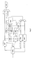
- Fig. 2 shows a block diagram of an RLL encoder according to the invention.
- a sequence of data blocks u i is input to a Control Block Builder 202.
- the Control Block Builder 202 having internally memorized the length of the tail part u tail,i -1 of the last processed data block u i -1 , assigns a certain number of bits from u i to its head part u head,i .
- the Control Block Builder 202 also assembles a polarity inverting control block 213 as ( u tail,i -1 , c inv,i , u head,i ).
- a counterpart, polarity preserving control block 214 is correspondingly composed as (u tail,i -1 , c pre,i , u head,i ), using a preserving control bit pattern c pre,i .
- the values of the preserving control bit pattern c pre,i and the inverting control bit pattern C inv,i are not constant, they depend on the context represented by the tail part u tail,i -1 and the head part u head,i surrounding them.
- the two control blocks 213, 214 thus composed are being dk-encoded in the subsequent First Control Block dk-encoder 208 and Second Control Block dk-encoder 209, respectively.
- a first and second dRDS Calculator 206, 207 calculate the Running Digital Sum differences dRDS inv ,dRDS pre of the dk-encoded polarity inverting and polarity preserving control blocks 213, 214, respectively.
- control block typically spans only a few bits
- the associated dk codewords and the corresponding dRDS values are advantageously stored in a lookup table, so that the functions of the first/second control block dk-encoder 208, 209 and the first/second dRDS calculator are actually achieved by two parallel memory readout operations.
- the Control Block Builder 202 strips it therefrom, forwarding only the body part u body,i and the tail part u tail,i to the subsequent Data Block dk-encoder 201.
- the Data Block dk-encoder 201 generates a dk-encoded body part v body,i , and feeds the tail part u tail,i which can not be encoded without look ahead, back to the Control Block Builder 202 to be processed together with the subsequent data block u i +1 .
- a third dRDS Calculator 203 calculates the body Running Digital Sum difference dRDS body .
- RDS inv RDS - dRDS body + dRDS inv . .
- a subsequent Control Block Selector 205 controls a multiplexer 210 to select, among the outputs of the first and second Control Block dk-encoder 208, 209, that dk-encoded output bitstream which corresponds to the control block which minimizes the absolute value of the RDS.
- the selected output bitstream consisting of a dk-encoded tail part v tail,i-1 of the previous data block u i -1 , of the dk-encoded control bits V ctrl,i and of the dk-encoded head part v head,i of the current data block u i is then concatenated in a time multiplexer 211 into the dk-encoded bitstream ⁇ i .
- Control Block Selector 205 forwards either the RDS of the parity preserving case RDS pre or the RDS of the parity inverting case RDS inv to an RDS register 204 for use in the next data block iteration, according to:
- the dk-encoded bitstream v i is precoded in a precoder 212 into a precoded stream w i .
- the Running Digital Sum calculations as described above amount to evaluating the Running Digital Sums at fixed positions at or near the boundaries of the data blocks, whereas the individual shape and slope of the RDS in between these evaluation positions is not being considered. Especially in the case of long data blocks, the random walk-like nature of the RDS as a function of the bit sequence index will be prominent, and selecting the control block by just looking at the RDS at the evaluation position may not be the optimal thing to do. It may be preferable to monitor the maxima and minima of RDS(i) and derive from these a selection criterion, instead.
- Fig. 4 shows a block diagram of an RLL-decoder to be used in connection with the RLL encoder according to the invention.
- a stream of readout bits, formatted into readout tuples x' is predecoded in a predecoder 403 into a stream of dk decodable tuples v', which in turn are dk-decoded in a dk-decoder 402 and are passed through a control bit extractor 401.
- the control bit extractor 401 simply extracts and removes the L c control bits after every L db data bits.
- a stream of RLL decoded tuples u' is obtained.
- the invention will now be applied to two industry standard RLL codes of look ahead and variable length type. For each of the two examples, it is shown how many head bits must be assigned and how the control bits must be set to make the control block either polarity preserving or polarity inverting. It is shown that the code of the first example needs at least 2 control bits to fulfil the method's requirements, and the code of the second example needs at least 3 control bits. The ideal case would be an RLL code requiring only a single control bit.
- Fig. 5 illustrates the first example, namely to use the invented method on the (1,7) RLL look ahead code according to US 4,337,458 .
- these cases correspond to a notion of "previous block has no tail", they are covered in lines 1 - 6 of the control bit insertion Table 503 shown in Fig. 5 .
- lines 1 - 2 cover the cases where the current data block starts with a "1", i.e. with a data word of "10" or "11".
- the preserving control bit pattern C pre,i and the inverting control bit pattern c inv,i are applied as depicted in the table lines, and the data word at the start of the current data block can be dk-encoded together with the subsequent bits.
- Lines 7 - 10 of the control bit insertion table 503 in Fig. 5 cover the cases where the last data word of the preceding data block must actually be considered a tail, because it cannot be dk-encoded without reference to subsequent bits outside that previous data block. This is the case when
- the Control bit insertion Table 503 of Fig. 5 reveals in lines 7 - 10 how the control bits have to be set for these cases of having a tail; to either preserve the polarity (i.e. to have an even number of "ones" within the coded control block) or to invert the polarity (i.e. to have an odd number of "ones" within the coded control block). With the given code, it so happens that no head bits need to be assigned to u i for these cases.
- Fig. 6 illustrates the second example, namely to use the invented method on a known (2,7) RLL variable length code using a single variable length basic coding table 601.
- the Control bit insertion table 602 of this RLL code is found through application of similar considerations as described above. Note that for this code, basic dk-encoding is done by independently translating groups of two, three, or four data bits to four, six, or eight code bits, respectively; the group length depending on the bit values. Note also, that with this given dk-encoding rule, it so happens that for the control blocks, cases exist where the control block must encompass both, a tail from the previous data block as well as a head from the current data block, as shown in lines 7 - 10 of the control bit insertion table 602 of Fig. 6 . As the control bit insertion table 602 shows, three control bits must be used here, resulting in a higher redundancy than in the example of Fig. 5 .
- control bits ( c inv ,c pre ) are periodically inserted into control blocks (108) which are dynamically placed and sized near the data block boundaries in such a way as to enable independent dk-encoding of the data blocks body ( u body,i ) and the control blocks (108).
- Running digital sum differences (dRDS inv ,dRDS pre , dRDS body ) are calculated.
- Control bit insertion is done in such a way that the d,k constraints of the RLL code are not violated, that the encoded dk sequence of the data block body (u body,i ) is not altered, and that the running digital sum (RDS) is minimized by eventually inverting the contribution of the data block body thereto. Compared to the number of data bits per data block, few control bits are sufficient to keep the digital sum variation DSV of the Running Digital Sum RDS small.
Landscapes
- Engineering & Computer Science (AREA)
- Theoretical Computer Science (AREA)
- Signal Processing (AREA)
- Signal Processing For Digital Recording And Reproducing (AREA)
Claims (8)
- Verfahren zur Kanalcodierung von Binärdaten, die aus einer Sequenz von Datenblöcken (ui) bestehen, wobei das Verfahren die folgenden Schritte umfasst:- Abtrennen von Anfangsblockteilen (uAnfangsblock,i) die individuelle Anfangsblock-Teillängen (LA,i) aufweisen, von den Datenblöcken (ui);- Trennen des Rests jedes der Datenblöcke (ui) in einen Rumpfteil (uRumpfteil,i) und in einen Endteil (UEnciteil,i), die individuelle Längen (LR,i, LE,i) aufweisen;- Kombinieren des Endteils eines vorhergehenden Datenblocks (uEndteil,i-1) mit einem umkehrenden Steuerbitmuster (cumk) und mit dem Anfangsblockteil eines gegenwärtigen Datenblocks (uAnfangsblock,i) zu einem polaritätsumkehrenden Steuerblock (213);- Kombinieren des Endteils des vorhergehenden Datenblocks (uEndteil,i-1) mit einem erhaltenden Steuerbitmuster (cerh) und mit dem Anfangsblockteil des gegenwärtigen Datenblocks (uAnfangsblock,i) zu einem polaritätserhaltenden Steuerblock (214),- dk-Codieren des polaritätsumkehrenden Steuerblocks (213) und des polaritätserhaltenden Steuerblocks (214);- Auswerten je einer Differenz laufender digitaler Summen (dRDSumk, dRDSerh) für den dk-codierten polaritätsumkehrenden Steuerblock (213) und für den dk-codierten polaritätserhaltenden Steuerblock (214); und Ableiten laufender digitaler Summen (RDSumk, RDSerh) für den paritätsumkehrenden Fall und für den paritätserhaltenden Fall daraus;- Auswählen des dk-codierten polaritätsumkehrenden Steuerblocks (213) oder des dk-codierten polaritätserhaltenden Steuerblocks (214), je nachdem, welche der laufenden digitalen Summen (RDSumk, RDSerh) einen kleineren Betrag hat, als einen ausgewählten Steuerblock;- Zeitmultiplexieren des ausgewählten Steuerblocks zusammen mit einem dk-codierten Rumpfteil (vRumpfteil,i) und NRZI-Modulieren des Ergebnisses zu den kanalcodierten Binärdaten wi;dadurch gekennzeichnet, dass die Anfangsblock-Teillängen (LA,i) individuell in der Weise gewählt werden, dass die dk-Codierung der Anfangsblockteile (uAnfangsblock,i) nicht von den nachfolgenden Resten der jeweiligen Datenblöcke (ui) abhängt, und dass die Rumpfteillängen (LR,i) individuell in der Weise gewählt werden, dass die dk-Codierung der Rumpfteile (uRumpfteil,i) nicht von den nachfolgenden Endteilen (uEndteil,i) der jeweiligen Datenblöcke (ui) abhängt.
- Verfahren nach Anspruch 1, bei dem der Schritt des Trennens umfasst:- Auffinden des Anfangs des Rumpfteils (URuwPfteil,i) eines Datenblocks (ui) als die erste Position innerhalb des Datenblocks (ui), bei der die beim zuweisen von Codebits zu Datenbits verwendete Bitgruppierung unabhängig von der zum Zuweisen innerhalb des dem Rumpfteil vorangehenden Steuerblocks verwendeten Gruppierung ist;- Auffinden des Anfangs des Endteils (uEndteil,i) eines Datenblocks (ui) als die erste Position innerhalb des Datenblocks (ui), bei der das Ableiten der Codebits für die Datenbits Informationen über mindestens ein Bit benötigt, das sich hinter dem Datenblock (ui) befindet.
- Verfahren nach Anspruch 1 oder 2, bei dem der Schritt des Ableitens einer laufenden digitalen Summe umfasst, dass zu einem vorhergehenden Wert der laufenden digitalen Summe das Folgende addiert wird:- für den paritätserhaltenden Fall: die Differenz laufender digitaler Summen (dRDSerh) des dk-codierten polaritätserhaltenden Steuerblocks (214) und eine Differenz laufender digitaler Summen (dRDSRumpfteil) des dk-codierten Rumpfteils (uRpumpftril,i),- für den paritätsumkehrenden Fall: die Differenz laufender digitaler Summen (dRDSumk) des dk-codierten paritätsumkehrenden Steuerblocks (213) und die negative Differenz laufender digitaler Summen (dRDSRumpteil) des dk-codierten Rumpfteils (uRumpfteil,i).
- Verfahren nach Anspruch 1 oder 2, bei dem die Schritte des dk-Codierens und Auswertens mit einer Tabellennachschlageoperation (213) ausgeführt werden.
- Verfahren nach Anspruch 4, bei dem der Schritt des Tabellennachschlagens umfasst:- Verwenden des Endteils des vorhergehenden Datenblocks (uEndteil,i-1) und des Anfangs des gegenwärtigen Datenblocks (ui) als einen Tabelleneintragsindex;- Abrufen, aus der dadurch zugegriffenen Tabellenzelle, des als das umkehrende Steuerbitmuster (cumk) zu verwendenden Werts und/oder des als das erhaltende Steuerbitmuster (cerh) zu verwendenden Werts und/oder von Codebits, die den dk-codierten Steuerblock bilden, und/oder des RDS-Beitrags des dk-codierten Steuerblocks (dRDSctrl).
- Vorrichtung zum Kanalcodieren von Binärdaten, die aus einer Sequenz von Datenblöcken (ui) bestehen, wobei die Vorrichtung umfasst:- eine Steuerblockbaueinrichtung (202), die so ausgestattet und konfiguriert ist, dass sie von den Datenblöcken (ui) Anfangsblockteile (uAnfangsblock,i), die individuelle Längen (LA,i) aufweisen, abtrennt; den Rest jedes der Datenblöcke (ui) in einen Rumpfteil (uRumpfteil,i) und in einen Endteil (uEndteil,i), die individuelle Längen (LR,i, LE,i) aufweisen, trennt; den Endteil eines vorhergehenden Datenblocks (uEndteil,i-1) mit einem umkehrenden Steuerbitmuster (cumk) und mit dem Anfangsblockteil des gegenwärtigen Datenblocks (uAnfangsblock,i) zu einem polaritätsumkehrenden Steuerblock (213) kombiniert und den Endteil des vorhergehenden Datenblocks (uEndteil,i-1) mit einem erhaltenden Steuerbitmuster (cerh) und mit dem Anfangsblockteil des gegenwärtigen Datenblocks (uAnfangsblock,i) zu einem polaritätserhaltenden Steuerblock (214) kombiniert;- einen dk-Codierer (201, 208, 209), der so ausgestattet und konfiguriert ist, dass er den polaritätsumkehrenden Steuerblock (213), den polaritätserhaltenden Steuerblock (214) und den Rumpfteil (uRumpfteil,i) dk-codiert;- eine Recheneinrichtung (203, 206, 207) für laufende digitale Summen, die so ausgestattet und konfiguriert ist, dass sie Differenzen laufender digitaler Summen (dPDSumk, dRDSerh, dRDSRumpfteil) des dk-codierten polaritätsumkehrenden Steuerblocks (213), des dk-codierten polaritätserhaltenden Steuerblocks (214) und des dk-codierten Rumpfteils berechnet; und daraus laufende digitale Summen (RDSumk, RDSerh) für den paritätsumkehrenden Fall und für den paritätserhaltenden Fall ableitet;- eine Auswahleinrichtung (205, 210, 211) zum Auswählen des dk-codierten polaritätsumkehrenden Steuerblocks (213) oder des dk-codierten polaritätserhaltenden Steuerblocks (214), je nachdem, welche der laufenden digitalen Summen einen kleineren Betrag hat, und zum Zeitmultiplexieren des ausgewählten Steuerblocks zusammen mit dem dk-codierten Rumpfteil (vRumpfteil,i); und- einen Modulator zum NRZI-Modulieren der zeitmultiplexierten Daten zu den kanalcodierten Binärdaten, (wi);dadurch gekennzeichnet, dass die Steuerblockbaueinrichtung (202) so ausgestattet und konfiguriert ist, dass sie die Anfangsblockteillängen (LA,i) individuell in der Weise wählt, dass das dk-Codieren der Anfangsblockteile (uAnfangsblock,i) nicht von den nachfolgenden Resten der jeweiligen Datenblöcke (ui) abhängt und dass sie die Rumpfteillängen (LR,i) individuell in der Weise wählt, dass die dk-Codierung der Rumpfteile (uRumpfteil,i) nicht von den nachfolgenden Endteilen (uEndteil,i) der jeweiligen Datenblöcke (ui) abhängt.
- Vorrichtung nach Anspruch 6, die außerdem eine Tabellennachschlageeinheit (213) umfasst, die so ausgestattet und konfiguriert ist, dass auf sie von der Steuerblockbaueinrichtung (202) und/oder von dem dk-Codierer (201, 208, 209) und/oder von der Berechnungseinrichtung (203, 206, 207) laufender digitaler Summen zugegriffen werden kann, wobei die Tabelle mindestens eine Art von Einträgen von als das jeweilige umkehrende Steuerbitmuster (cumk) zu verwendenden Werten, von als das jeweilige erhaltende Steuerbitmuster (cerh) zu verwendenden Werten, von Codebits, die den jeweiligen dk-codierten Steuerblock bilden, und von RDS-Beiträgen (dRDSStrg) des jeweiligen dk-codierten Steuerblocks enthält.
- Verfahren nach einem der Ansprüche 1 bis 5 oder Vorrichtung nach einem der Ansprüche 6 und 7, bei dem/der die kürzestmögliche Anfangsblock-Teillänge (LA,i) und die kürzestmögliche Endteillänge (LE,i) verwendet werden.
Priority Applications (1)
| Application Number | Priority Date | Filing Date | Title |
|---|---|---|---|
| EP08305114A EP1990919B1 (de) | 2007-05-07 | 2008-04-18 | Verfahren und Vorrichtung zur Kanalkodierung |
Applications Claiming Priority (2)
| Application Number | Priority Date | Filing Date | Title |
|---|---|---|---|
| EP07107630A EP1990918A1 (de) | 2007-05-07 | 2007-05-07 | Verfahren und Vorrichtung zur Kanalkodierung |
| EP08305114A EP1990919B1 (de) | 2007-05-07 | 2008-04-18 | Verfahren und Vorrichtung zur Kanalkodierung |
Publications (2)
| Publication Number | Publication Date |
|---|---|
| EP1990919A1 EP1990919A1 (de) | 2008-11-12 |
| EP1990919B1 true EP1990919B1 (de) | 2010-01-06 |
Family
ID=38566294
Family Applications (2)
| Application Number | Title | Priority Date | Filing Date |
|---|---|---|---|
| EP07107630A Withdrawn EP1990918A1 (de) | 2007-05-07 | 2007-05-07 | Verfahren und Vorrichtung zur Kanalkodierung |
| EP08305114A Not-in-force EP1990919B1 (de) | 2007-05-07 | 2008-04-18 | Verfahren und Vorrichtung zur Kanalkodierung |
Family Applications Before (1)
| Application Number | Title | Priority Date | Filing Date |
|---|---|---|---|
| EP07107630A Withdrawn EP1990918A1 (de) | 2007-05-07 | 2007-05-07 | Verfahren und Vorrichtung zur Kanalkodierung |
Country Status (3)
| Country | Link |
|---|---|
| US (1) | US7773001B2 (de) |
| EP (2) | EP1990918A1 (de) |
| DE (1) | DE602008000494D1 (de) |
Families Citing this family (4)
| Publication number | Priority date | Publication date | Assignee | Title |
|---|---|---|---|---|
| EP2187397A1 (de) * | 2008-11-05 | 2010-05-19 | Thomson Licensing | Verfahren und Vorrichtung zur Löschungsverschlüsselung in einem ECC-codierten Bitstrom |
| US8984369B2 (en) * | 2012-11-21 | 2015-03-17 | Micron Technology, Inc. | Shaping codes for memory |
| US20200356519A1 (en) * | 2018-03-29 | 2020-11-12 | Wayne Ballantyne | Techniques for serial communication |
| CN109412600A (zh) * | 2018-09-03 | 2019-03-01 | 何祥果 | 一种基于磁性特征的标识号编码方法 |
Family Cites Families (8)
| Publication number | Priority date | Publication date | Assignee | Title |
|---|---|---|---|---|
| US4337458A (en) | 1980-02-19 | 1982-06-29 | Sperry Corporation | Data encoding method and system employing two-thirds code rate with full word look-ahead |
| US5151699A (en) | 1990-09-05 | 1992-09-29 | Pioneer Electronic Corporation | Data converting apparatus |
| US6839004B2 (en) * | 2001-11-27 | 2005-01-04 | Seagate Technology Llc | High rate run length limited code |
| JP4132804B2 (ja) * | 2001-12-11 | 2008-08-13 | ソニー株式会社 | 変調装置および方法、記録媒体、並びにプログラム |
| JP3769753B2 (ja) * | 2003-03-24 | 2006-04-26 | ソニー株式会社 | 符号化装置および符号化方法、記録媒体、並びにプログラム |
| KR20070054241A (ko) * | 2004-09-15 | 2007-05-28 | 코닌클리케 필립스 일렉트로닉스 엔.브이. | 코더와, r=2의 rmtr 제약을 갖는 코드의 코딩방법 |
| US7142135B1 (en) * | 2005-09-06 | 2006-11-28 | Media Tek Inc. | Modulation methods and systems |
| US7378994B1 (en) * | 2007-01-08 | 2008-05-27 | Mediatek, Inc. | EFM/EFM+ encoder and method thereof |
-
2007
- 2007-05-07 EP EP07107630A patent/EP1990918A1/de not_active Withdrawn
-
2008
- 2008-04-18 EP EP08305114A patent/EP1990919B1/de not_active Not-in-force
- 2008-04-18 DE DE602008000494T patent/DE602008000494D1/de active Active
- 2008-04-30 US US12/150,680 patent/US7773001B2/en not_active Expired - Fee Related
Also Published As
| Publication number | Publication date |
|---|---|
| EP1990918A1 (de) | 2008-11-12 |
| EP1990919A1 (de) | 2008-11-12 |
| US7773001B2 (en) | 2010-08-10 |
| US20080278356A1 (en) | 2008-11-13 |
| DE602008000494D1 (de) | 2010-02-25 |
Similar Documents
| Publication | Publication Date | Title |
|---|---|---|
| US6150964A (en) | M=10 (2,10), D=3.75 runlength limited code for multi-level data | |
| EP0771078B1 (de) | Verfahren und Anordnung zur Erzeugung eines lauflängebegrenzten Codes mit Gleichstromsteuerung | |
| EP0344903A2 (de) | Coderegel-Verletzungsumsetzer für einen (d,k) Code | |
| KR100778885B1 (ko) | 이진 정보신호의 데이터 비트의 스트림을 제약을 받는 이진 채널신호의 데이터 비트의 스트림으로 변환하는 방법, 인코딩 장치, 기록매체와, 디코딩장치 | |
| AU1256499A (en) | Device for encoding/decoding N-bit source words into corresponding M-bit channelwords, and vice versa | |
| EP1990919A1 (de) | Verfahren und Vorrichtung zur Kanalkodierung | |
| KR101332142B1 (ko) | Lto-5 테이프용 rll 인코딩 | |
| US5781130A (en) | M-ary (d,k) runlength limited coding for multi-level data | |
| WO2001058102A9 (en) | Dc control of a multilevel signal | |
| HUP0202426A2 (en) | Method of converting a stream of databits of a binary information signal, into a stream of databits of a constrained binary channel signal, device for encoding, signal comprising a stream of databits of a constrained binary channel signal, ... | |
| US6545615B2 (en) | Device for encoding a stream of databits of a binary source signal into a stream of databits of a binary channel signal, memory means, device for recording information, record carrier, device for coding and device for playing back | |
| CN101221775A (zh) | Efm编码器及其采用的数字总和数值保护的方法 | |
| US5757293A (en) | M=8 (1,2) runlength limited code for multi-level data | |
| US6232896B1 (en) | Device for encoding n-bit source words into corresponding m-bit channel words and decoding m-bit channel words into corresponding n-bit source words | |
| Davey et al. | Two dimensional coding for a multiple-track, maximum-likelihood digital magnetic storage system | |
| US5657014A (en) | M=7 (3,7) runlength limited code for multi-level data | |
| US5682154A (en) | M=4 (1,2) runlength limited code for multi-level data | |
| US5682155A (en) | M=6(4,11) runlength limited code for multi-level data | |
| US5748118A (en) | M=7 (3,8) runlength limited code for multi-level data | |
| US5668546A (en) | M=6 (3,6) runlength limited code for multi-level data | |
| US5748117A (en) | M=8 (1,3) runlength limited code for multi-level data | |
| US5659310A (en) | M=5 (0,2) runlength limited code for multi-level data | |
| US5663723A (en) | M=7 (1,3) runlength limited code for multi-level data | |
| US5659311A (en) | M=6 (2,4) runlength limited code for multi-level data | |
| US5680128A (en) | M=6(3,8) runlength limited code for multi-level data |
Legal Events
| Date | Code | Title | Description |
|---|---|---|---|
| PUAI | Public reference made under article 153(3) epc to a published international application that has entered the european phase |
Free format text: ORIGINAL CODE: 0009012 |
|
| AK | Designated contracting states |
Kind code of ref document: A1 Designated state(s): AT BE BG CH CY CZ DE DK EE ES FI FR GB GR HR HU IE IS IT LI LT LU LV MC MT NL NO PL PT RO SE SI SK TR |
|
| AX | Request for extension of the european patent |
Extension state: AL BA MK RS |
|
| 17P | Request for examination filed |
Effective date: 20090518 |
|
| AKX | Designation fees paid |
Designated state(s): DE FR GB |
|
| GRAP | Despatch of communication of intention to grant a patent |
Free format text: ORIGINAL CODE: EPIDOSNIGR1 |
|
| GRAS | Grant fee paid |
Free format text: ORIGINAL CODE: EPIDOSNIGR3 |
|
| GRAA | (expected) grant |
Free format text: ORIGINAL CODE: 0009210 |
|
| AK | Designated contracting states |
Kind code of ref document: B1 Designated state(s): DE FR GB |
|
| REG | Reference to a national code |
Ref country code: GB Ref legal event code: FG4D |
|
| RAP2 | Party data changed (patent owner data changed or rights of a patent transferred) |
Owner name: THOMSON LICENSING |
|
| REF | Corresponds to: |
Ref document number: 602008000494 Country of ref document: DE Date of ref document: 20100225 Kind code of ref document: P |
|
| REG | Reference to a national code |
Ref country code: GB Ref legal event code: 746 Effective date: 20100209 |
|
| PLBE | No opposition filed within time limit |
Free format text: ORIGINAL CODE: 0009261 |
|
| STAA | Information on the status of an ep patent application or granted ep patent |
Free format text: STATUS: NO OPPOSITION FILED WITHIN TIME LIMIT |
|
| 26N | No opposition filed |
Effective date: 20101007 |
|
| REG | Reference to a national code |
Ref country code: FR Ref legal event code: PLFP Year of fee payment: 9 |
|
| PGFP | Annual fee paid to national office [announced via postgrant information from national office to epo] |
Ref country code: GB Payment date: 20160421 Year of fee payment: 9 Ref country code: DE Payment date: 20160411 Year of fee payment: 9 |
|
| PGFP | Annual fee paid to national office [announced via postgrant information from national office to epo] |
Ref country code: FR Payment date: 20160420 Year of fee payment: 9 |
|
| REG | Reference to a national code |
Ref country code: DE Ref legal event code: R119 Ref document number: 602008000494 Country of ref document: DE |
|
| GBPC | Gb: european patent ceased through non-payment of renewal fee |
Effective date: 20170418 |
|
| REG | Reference to a national code |
Ref country code: FR Ref legal event code: ST Effective date: 20171229 |
|
| PG25 | Lapsed in a contracting state [announced via postgrant information from national office to epo] |
Ref country code: FR Free format text: LAPSE BECAUSE OF NON-PAYMENT OF DUE FEES Effective date: 20170502 Ref country code: DE Free format text: LAPSE BECAUSE OF NON-PAYMENT OF DUE FEES Effective date: 20171103 |
|
| PG25 | Lapsed in a contracting state [announced via postgrant information from national office to epo] |
Ref country code: GB Free format text: LAPSE BECAUSE OF NON-PAYMENT OF DUE FEES Effective date: 20170418 |