EP1990565B1 - Sealing ring and seal assembly, enclosing the sealing ring - Google Patents
Sealing ring and seal assembly, enclosing the sealing ring Download PDFInfo
- Publication number
- EP1990565B1 EP1990565B1 EP20070009010 EP07009010A EP1990565B1 EP 1990565 B1 EP1990565 B1 EP 1990565B1 EP 20070009010 EP20070009010 EP 20070009010 EP 07009010 A EP07009010 A EP 07009010A EP 1990565 B1 EP1990565 B1 EP 1990565B1
- Authority
- EP
- European Patent Office
- Prior art keywords
- spring
- sealing ring
- sealing
- sealed
- sealing lip
- Prior art date
- Legal status (The legal status is an assumption and is not a legal conclusion. Google has not performed a legal analysis and makes no representation as to the accuracy of the status listed.)
- Active
Links
Images


Classifications
-
- F—MECHANICAL ENGINEERING; LIGHTING; HEATING; WEAPONS; BLASTING
- F16—ENGINEERING ELEMENTS AND UNITS; GENERAL MEASURES FOR PRODUCING AND MAINTAINING EFFECTIVE FUNCTIONING OF MACHINES OR INSTALLATIONS; THERMAL INSULATION IN GENERAL
- F16J—PISTONS; CYLINDERS; SEALINGS
- F16J15/00—Sealings
- F16J15/16—Sealings between relatively-moving surfaces
- F16J15/32—Sealings between relatively-moving surfaces with elastic sealings, e.g. O-rings
- F16J15/3204—Sealings between relatively-moving surfaces with elastic sealings, e.g. O-rings with at least one lip
- F16J15/3208—Sealings between relatively-moving surfaces with elastic sealings, e.g. O-rings with at least one lip provided with tension elements, e.g. elastic rings
- F16J15/3212—Sealings between relatively-moving surfaces with elastic sealings, e.g. O-rings with at least one lip provided with tension elements, e.g. elastic rings with metal springs
-
- F—MECHANICAL ENGINEERING; LIGHTING; HEATING; WEAPONS; BLASTING
- F16—ENGINEERING ELEMENTS AND UNITS; GENERAL MEASURES FOR PRODUCING AND MAINTAINING EFFECTIVE FUNCTIONING OF MACHINES OR INSTALLATIONS; THERMAL INSULATION IN GENERAL
- F16F—SPRINGS; SHOCK-ABSORBERS; MEANS FOR DAMPING VIBRATION
- F16F1/00—Springs
- F16F1/02—Springs made of steel or other material having low internal friction; Wound, torsion, leaf, cup, ring or the like springs, the material of the spring not being relevant
- F16F1/04—Wound springs
- F16F1/12—Attachments or mountings
Definitions
- the invention relates to a sealing ring comprising at least one dynamically stressed sealing lip which can be applied under elastic prestressing sealing to a sealed surface of a machine element to be sealed, wherein the sealing lip is radially outer peripheral side enclosed by an annular spring, wherein the spring has the shape of a helical compression spring, with Windings, which are associated with each other in the circumferential direction at a distance adjacent.
- Sealing rings are well known.
- the previously known sealing rings are formed for example as radial shaft seals, arranged in a relatively immovable housings stationary and dense rotating waves.
- the necessary for the sealing function of a radial shaft seal contact pressure of the sealing lip to the surface to be sealed is achieved in these cases by the radial expansion of the elastic sealing lip, which usually consists of an elastomeric material, and also by a tension spring which surrounds the outer edge of the sealing lip.
- the elastic sealing lip which usually consists of an elastomeric material
- a tension spring which surrounds the outer edge of the sealing lip.
- tension springs can be used with increased rigidity, the contact pressure of the spring by the winding ratio w (mean coil diameter of the spring to wire diameter) limits are set. Even with maximum utilization of this ratio, a lifting of the sealing lip at speeds greater than 5000 min -1 can no longer be prevented.
- seals which have at least one statically stressed sealing bead and are mounted with this stationary on the axis.
- the dynamically stressed sealing lip points radially outward and seals the inner peripheral side wall of a rotating housing.
- the necessary contact pressure of the sealing lip to the housing is achieved by a compression spring, wherein such a seal arrangement has an undesirably high friction between the sealing lip and housing due to the compression of the sealing lip and the compression spring.
- a helical spring having a number of interconnected connections which are spaced apart from one another. Each turn is at a predetermined acute angle to the center line of the Coil spring, so that the coil spring of its deflection in a loading direction, which extends approximately perpendicular to the center line of the coil spring, in a predetermined range opposes a substantially constant force.
- the ends of the spring may be connected to a ring. The object to be achieved is seen in compensating for changing conditions, such as dimensional changes due to wear, temperature and pressure change, with constant force of the coil spring.
- the helical spring can be used in a sealing ring made of elastomeric material, wherein a distance between the windings of about 0.2 mm is described for the illustrated embodiment.
- the sealing ring seals rotating or oscillating waves and is arranged in a stationary housing.
- a sealing ring is known, with a dynamically stressed sealing lip, which can be applied under elastic prestressing sealing to a sealed surface of an axis to be sealed.
- the sealing lip is held by a tension spring on the surface to be sealed, wherein the object of the prior art sealing ring is seen therein to keep the sealing lip on the surface to be sealed at high speeds of the sealing ring.
- the tension spring be held by holding devices on the surface to be sealed. These holding devices may be formed, for example, in that the tension spring is largely embedded in the elastomeric material of the sealing lip.
- the tension spring is in Fig. 3 schematically illustrated, which is described in the figure description that the tension spring is enclosed by a rubber body.
- the tension spring has a coil diameter of 4 mm, the wire diameter being 0.9 mm. According to another embodiment, the Winding diameter 3 mm, while the wire diameter is 0.45 mm. The winding ratio is therefore in one case about 4.5 in the other case 6.7.
- sealing ring which has a spring-loaded sealing lip.
- the previously known sealing ring is designed as a radial shaft seal, for sealing a rotating shaft, wherein the friction between the sealing lip and the machine element to be sealed is to be reduced to a minimum. Under dynamic conditions, the static sealing lip should be lifted off the surface to be sealed.
- the invention has the object of providing a simple standard sealing ring of the type mentioned in such a way that even at speeds of the sealing ring> 5000 min -1 secure sealing of the dynamically stressed sealing lip on the surface to be sealed is given to be sealed axis, that is, a lifting of the sealing lip of the surface to be sealed and / or jumping off the tension spring of the sealing lip under the conditions mentioned is avoided.
- a sealing ring in which the spring to compensate for operational centrifugal forces has adjacent turns having a pitch of 1.5 mm to 2.3 mm, wherein adjacent turns neither in the manufacturing condition nor during the Touch as directed.
- a spring has, based on conventional springs, in which adjacent turns in the condition of the condition of the sealing ring (unloaded state) abut each other at least on the inner circumference side, the advantage that adjacent turns of the spring of the sealing ring according to the invention by the same circumference by its configuration on the inner peripheral side are always arranged with a circumferential distance from each other and that such a spring has a much lower mass. Since the centrifugal force acting on the spring is proportional to the mass of the spring and the number of revolutions squared, a spring in which adjacent turns are always arranged circumferentially adjacent to each other can have up to 80% less mass.
- the spring has the shape of a helical compression spring.
- the adjacent turns of the annular spring have a pitch of at least 1.5 mm.
- the spring characteristic can under Others also be influenced by the slope of the spring winding. The greater the pitch of the spring coil, the higher the stiffness of the spring.
- sealing rings according to the invention can also be used arrive when in rotating cases with speeds of z. B. 12000 min -1 and more are operated. Even at these high speeds, a reliable contact pressure of the sealing lip is achieved on the surface to be sealed by the special design of the spring.
- the two front ends of the production-related straight spring may be formed together as a spring lock. It is advantageous that the ends of the spring can be easily and inexpensively connect to each other, for example, the fact that the spring for connecting the two ends together is first turned on something that the two ends then connected together and connect the spin automatically reversed becomes. Subsequently, the spring is annular.
- the spring may have a winding ratio w ⁇ 4.
- the winding ratio w describes the ratio of the mean winding diameter of the spring to the wire diameter. Winding ratios w ⁇ 4.5 are conventional
- the sealing lip is preferably made of an elastomeric material. Sealing rings with sealing lips made of elastomeric materials can be particularly easily adapted to the particular circumstances of the application and are simple and inexpensive to produce.
- the invention also relates to a sealing arrangement, comprising a sealing ring as described above, wherein the sealing ring with its sealing lip sealingly seals a sealed surface of an axis to be sealed under radial prestress, wherein the sealing ring is stationary in a housing and rotatably disposed together with the housing about the axis ,
- a seal arrangement is used, for example, for sealing hubs in cars or trucks or for sealing centrifuges or retarders.
- Such a seal assembly is tight even at speeds in the range of 12000 min -1 , since the sealing lip does not stand out from the surface to be sealed by the special, previously described spring even at such high speeds; In addition, the high stiffness of the spring, the risk that it jumps, reduced to a minimum.
- the invention relates to the use of a helical compression spring as a spring of a sealing ring and a sealing arrangement, each as described above.
- a helical compression spring as a spring of a sealing ring and a sealing arrangement, each as described above.
- Sealing rings with sealing lips made of elastomeric materials are also used when they rotate at speeds of more than 5000 min -1 around an axis. Expensive special designs for sealing under these operating conditions are therefore not required. Sealing rings, which have excellent performance characteristics for a long service life for this particular application, are easy and inexpensive to produce.
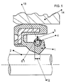
- FIG. 1 an embodiment of the seal assembly according to the invention is shown.
- the sealing arrangement comprises the sealing ring, which is designed as a radial shaft seal and has a dynamically stressed sealing lip 1.
- the dynamically stressed sealing lip 1 surrounds the sealed surface 2 of the sealed axis 3 under elastic prestressing sealing, wherein the sealing lip 1 is radially outer peripheral side of the annular spring 4 is enclosed.
- the sealing ring is pressed in place in the housing 14 and runs together with the housing 14 about the axis 3.
- the spring 4 is corresponding to the Figures 2 and 3 educated.
- FIG. 2 and 3 is the spring 4 off FIG. 1 shown as a single part.
- the spring 4 has turns 6.1, 6.2,. FIG. 2 ) / peripheral ( FIG. 3 ) Distance 7 are assigned adjacent.
- the spring 4 has the shape of a helical compression spring, wherein the adjacent turns 6.1, 6.2; 6.2, 6.3; ... have a pitch 8 of 1.5 mm in the exemplary embodiment shown here. Neither in the manufacturing condition ( FIG. 2 ), during the intended use ( FIG. 1 and FIG. 3 ) adjacent turns 6.1, 6.2; 6.2, 6.3; ....
- the two ends 9, 10 of the spring 4 are formed such that they, as in FIG. 3 shown, form a spring lock 11.
- the spring 4 has in the embodiment shown here, a winding ratio w of 3.8.
- a stiffness of the spring is achieved, which is proportional to the slope, wherein the spring has a lower mass, the greater the slope.
- FIGS. 4 and 5 conventional tension springs are shown as they are used in the prior art.
- the adjacent turns 6.1, 6.2, 6.3, ... are directly adjacent to each other and the number of turns 6.1, 6.2, 6.3, ... is comparatively large, whereby a high mass is conditional.
Description
Die Erfindung betrifft einen Dichtring, umfassend zumindest eine dynamisch beanspruchte Dichtlippe, die unter elastischer Vorspannung dichtend an eine abzudichtende Oberfläche eines abzudichtenden Maschinenelements anlegbar ist, wobei die Dichtlippe radial außenumfangsseitig von einer ringförmigen Feder umschlossen ist, wobei die Feder die Gestalt einer Schraubendruckfeder aufweist, mit Windungen, die einander in Umfangsrichtung mit Abstand benachbart zugeordnet sind.The invention relates to a sealing ring comprising at least one dynamically stressed sealing lip which can be applied under elastic prestressing sealing to a sealed surface of a machine element to be sealed, wherein the sealing lip is radially outer peripheral side enclosed by an annular spring, wherein the spring has the shape of a helical compression spring, with Windings, which are associated with each other in the circumferential direction at a distance adjacent.
Dichtringe sind allgemein bekannt. Die vorbekannten Dichtringe sind beispielsweise als Radialwellendichtringe ausgebildet, in relativ unbeweglichen Gehäusen ortsfest angeordnet und dichten rotierende Wellen ab. Die für die Dichtfunktion eines Radialwellendichtrings notwendige Anpresskraft der Dichtlippe an die abzudichtende Oberfläche wird in diesen Fällen durch die radiale Aufdehnung der elastischen Dichtlippe, die zumeist aus einem elastomeren Werkstoff besteht, und außerdem durch eine Zugfeder erreicht, die die Dichtlippe außenumfangsseitig umschließt.
Werden die vorbekannten Radialwellendichtringe ortsfest in um Achsen umlaufende Gehäuse eingebaut, wie beispielsweise in Radnaben von PKW, LKW oder in Sonderaggregaten wie z. B. in Retadem, müssen im Betrieb auftretende Zentrifugalkräfte, die auf die Dichtlippe und die Zugfeder wirken, durch die Anpresskraft der Dichtlippe und der Zugfeder kompensiert werden. Dies gelingt aber nur einigermaßen zuverlässig, so lange die Drehzahl von Gehäuse und Radialwellendichtring eine Drehzahl von etwa 2000 min-1 nicht überschreiten. Bei höheren Drehzahlen reichen die Anpresskraft der Dichtlippe und die Anpresskraft der Zugfeder nicht mehr aus, die Dichtlippe zuverlässig auf der abzudichtenden Oberfläche zu halten. Die Dichtlippe hebt von der Oberfläche ab. Es kommt zu unerwünscht hohen Leckagen.
Um die Dichtlippe auch bei höheren Drehzahlen länger auf der abzudichtenden Oberfläche zu halten, können auch Zugfedern mit erhöhter Steifigkeit eingesetzt werden, wobei der Anpresskraft der Feder durch das Wickelverhältnis w (mittlerer Windungsdurchmesser der Feder zu Drahtdurchmesser) Grenzen gesetzt sind. Auch bei maximaler Ausnutzung dieses Verhältnisses kann ein Abheben der Dichtlippe bei Drehzahlen größer 5000 min-1 nicht mehr verhindert werden.Sealing rings are well known. The previously known sealing rings are formed for example as radial shaft seals, arranged in a relatively immovable housings stationary and dense rotating waves. The necessary for the sealing function of a radial shaft seal contact pressure of the sealing lip to the surface to be sealed is achieved in these cases by the radial expansion of the elastic sealing lip, which usually consists of an elastomeric material, and also by a tension spring which surrounds the outer edge of the sealing lip.
If the previously known radial shaft seals are installed in a stationary manner in axes surrounding the housing, such as in wheel hubs of cars, Truck or in special units such. As in Retadem, occurring during operation centrifugal forces acting on the sealing lip and the tension spring, be compensated by the contact pressure of the sealing lip and the tension spring. But this succeeds only reasonably reliable, as long as the speed of the housing and radial shaft sealing ring does not exceed a speed of about 2000 min -1 . At higher speeds, the contact pressure of the sealing lip and the contact force of the tension spring are no longer sufficient to reliably hold the sealing lip on the surface to be sealed. The sealing lip lifts off the surface. It comes to undesirably high leakage.
To keep the sealing lip longer at higher speeds on the surface to be sealed, tension springs can be used with increased rigidity, the contact pressure of the spring by the winding ratio w (mean coil diameter of the spring to wire diameter) limits are set. Even with maximum utilization of this ratio, a lifting of the sealing lip at speeds greater than 5000 min -1 can no longer be prevented.
Außerdem sind Sonderdichtungen bekannt, die zumindest einen statisch beanspruchten Dichtwulst aufweisen und mit diesem ortsfest auf der Achse montiert sind. Die dynamisch beanspruchte Dichtlippe weist radial nach außen und dichtet die innenumfangsseitige Wand eines rotierenden Gehäuses ab. Die notwendige Anpresskraft der Dichtlippe an das Gehäuse wird durch eine Druckfeder erreicht, wobei eine solche Dichtungsanordnung eine unerwünscht hohe Reibung zwischen Dichtlippe und Gehäuse aufgrund der Stauchung der Dichtlippe und der Druckfeder aufweist.In addition, special seals are known, which have at least one statically stressed sealing bead and are mounted with this stationary on the axis. The dynamically stressed sealing lip points radially outward and seals the inner peripheral side wall of a rotating housing. The necessary contact pressure of the sealing lip to the housing is achieved by a compression spring, wherein such a seal arrangement has an undesirably high friction between the sealing lip and housing due to the compression of the sealing lip and the compression spring.
Aus der
Aus der
Die Dichtlippe wird von einer Zugfeder auf der abzudichtenden Oberfläche gehalten, wobei die Aufgabe des vorbekannten Dichtrings darin gesehen wird, die Dichtlippe auch bei hohen Drehzahlen des Dichtrings auf der abzudichtenden Oberfläche der Achse zu halten.
Zur Lösung der Aufgabe ist es vorgesehen, dass die Zugfeder durch Halteeinrichtungen auf der abzudichtenden Oberfläche gehalten werden. Diese Halteeinrichtungen können beispielsweise dadurch gebildet sein, dass die Zugfeder im elastomeren Werkstoff der Dichtlippe weitgehend eingebettet ist. Die Zugfeder ist in
To achieve the object, it is provided that the tension spring be held by holding devices on the surface to be sealed. These holding devices may be formed, for example, in that the tension spring is largely embedded in the elastomeric material of the sealing lip. The tension spring is in
Aus der
Aus der
Der Erfindung liegt die Aufgabe zugrunde, einen einfachen Standard-Dichtring der eingangs genannten Art derart weiterzuentwickeln, dass auch bei Drehzahlen des Dichtrings > 5000 min-1 eine sichere Abdichtung der dynamisch beanspruchten Dichtlippe auf der abzudichtenden Oberfläche der abzudichtenden Achse gegeben ist, d. h., dass ein Abheben der Dichtlippe von der abzudichtenden Oberfläche und/oder ein Abspringen der Zugfeder von der Dichtlippe unter den genannten Bedingungen sicher vermieden wird.The invention has the object of providing a simple standard sealing ring of the type mentioned in such a way that even at speeds of the sealing ring> 5000 min -1 secure sealing of the dynamically stressed sealing lip on the surface to be sealed is given to be sealed axis, that is, a lifting of the sealing lip of the surface to be sealed and / or jumping off the tension spring of the sealing lip under the conditions mentioned is avoided.
Diese Aufgabe wird erfindungsgemäß mit den Merkmalen von Anspruch 1 gelöst. Auf vorteilhafte Ausgestaltungen nehmen die Unteransprüche Bezug.This object is achieved with the features of claim 1. In advantageous embodiments, the dependent claims relate.
Zur Lösung der Aufgabe ist ein Dichtring vorgesehen, bei dem die Feder zum Ausgleich von betriebsbedingten Zentrifugalkräften einander benachbarte Windungen aufweist, die eine Steigung von 1,5 mm bis 2,3 mm aufweisen, wobei einander benachbarte Windungen sich weder im herstellungsbedingten Zustand noch während der bestimmungsgemäßen Verwendung berühren. Eine solche Feder hat, bezogen auf herkömmliche Zugfedern, bei denen einander benachbarte Windungen im herstellungsbedingten Zustand des Dichtrings (unbelasteter Zustand) zumindest innenumfangsseitig direkt aneinander anliegen, den Vorteil, dass einander benachbarte Windungen der Feder des erfindungsgemäßen Dichtrings bei gleichem Umfang durch ihre Ausgestaltung auch innenumfangsseitig stets mit umfangsseitigem Abstand zueinander angeordnet sind und dass eine solche Feder eine deutlich geringere Masse aufweist.
Da die auf die Feder wirkende Zentrifugalkraft proportional zur Masse der Feder und der Drehzahl zum Quadrat ist, kann eine Feder, bei der einander benachbarte Windungen stets mit umfangsseitigem Abstand benachbart zueinander angeordnet sind, eine um bis zu 80 % geringere Masse haben.To solve the problem, a sealing ring is provided, in which the spring to compensate for operational centrifugal forces has adjacent turns having a pitch of 1.5 mm to 2.3 mm, wherein adjacent turns neither in the manufacturing condition nor during the Touch as directed. Such a spring has, based on conventional springs, in which adjacent turns in the condition of the condition of the sealing ring (unloaded state) abut each other at least on the inner circumference side, the advantage that adjacent turns of the spring of the sealing ring according to the invention by the same circumference by its configuration on the inner peripheral side are always arranged with a circumferential distance from each other and that such a spring has a much lower mass.
Since the centrifugal force acting on the spring is proportional to the mass of the spring and the number of revolutions squared, a spring in which adjacent turns are always arranged circumferentially adjacent to each other can have up to 80% less mass.
Die Feder weist die Gestalt einer Schraubendruckfeder auf.The spring has the shape of a helical compression spring.
Die einander benachbarten Windungen der ringförmigen Feder weisen eine Steigung von zumindest 1,5 mm auf. Die Federcharakteristik kann unter anderem auch durch die Steigung der Federwicklung beeinflusst werden. Je größer die Steigung der Federwicklung, desto höher ist die Steifigkeit der Feder. Durch die zuvor beschriebene Reduzierung der Masse der Feder, die eine entsprechend geringere Zentrifugalkraft, die im Betrieb des Dichtrings auf die Zugfeder wirkt, zur Folge hat einerseits und die mit größerer Steigung der Federwicklung höhere Steifigkeit der Feder andererseits, können erfindungsgemäße Dichtringe auch dann zur Anwendung gelangen, wenn diese in rotierenden Gehäusen mit Drehzahlen von z. B. 12000 min-1 und mehr betrieben werden. Auch bei diesen hohen Drehzahlen wird durch die spezielle Ausgestaltung der Feder eine zuverlässige Anpressung der Dichtlippe an die abzudichtende Oberfläche erreicht.The adjacent turns of the annular spring have a pitch of at least 1.5 mm. The spring characteristic can under Others also be influenced by the slope of the spring winding. The greater the pitch of the spring coil, the higher the stiffness of the spring. By reducing the mass of the spring described above, which has a correspondingly lower centrifugal force acting on the tension spring in operation of the sealing ring on the one hand and the higher stiffness of the spring with a greater pitch of the spring winding on the other hand, sealing rings according to the invention can also be used arrive when in rotating cases with speeds of z. B. 12000 min -1 and more are operated. Even at these high speeds, a reliable contact pressure of the sealing lip is achieved on the surface to be sealed by the special design of the spring.
Für die meisten gängigen Abmessungen von Dichtringen ist die genannte Steigung von hervorzuhebendem Vorteil. Je größer die Steigung der Federwicklung, desto geringer ist, bei gleichem Umfang der Feder, die Masse und desto größer ist die Federsteifigkeit. Die Steigung beträgt zumindest 1,5 mm.For most common dimensions of sealing rings, the said slope of hervorzuhebendem advantage. The greater the pitch of the spring coil, the lower, with the same circumference of the spring, the mass and the greater the spring stiffness. The slope is at least 1.5 mm.
Die beiden stirnseitigen Enden der herstellungsbedingt geraden Feder können zusammen als Federschloss ausgebildet sein. Hierbei ist von Vorteil, dass sich die Enden der Feder einfach und kostengünstig miteinander verbinden lassen, beispielsweise dadurch, dass die Feder zur Verbindung der beiden Enden miteinander zunächst etwas aufgedreht wird, dass die beiden Enden anschließend miteinander verbunden und die Aufdrehung anschließen selbsttätig wieder rückgängig gemacht wird. Anschließend ist die Feder ringförmig ausgebildet.The two front ends of the production-related straight spring may be formed together as a spring lock. It is advantageous that the ends of the spring can be easily and inexpensively connect to each other, for example, the fact that the spring for connecting the two ends together is first turned on something that the two ends then connected together and connect the spin automatically reversed becomes. Subsequently, the spring is annular.
Die Feder kann ein Wickelverhältnis w < 4 aufweisen. Das Wickelverhältnis w beschreibt das Verhältnis aus mittlerem Windungsdurchmesser der Feder zum Drahtdurchmesser. Wickelverhältnisse w < 4,5 sind bei herkömmlichenThe spring may have a winding ratio w <4. The winding ratio w describes the ratio of the mean winding diameter of the spring to the wire diameter. Winding ratios w <4.5 are conventional
Federn nicht zu realisieren. Bei der erfindungsgemäßen Feder ist ein Wickelverhältnis < 4 ideal, weil bei gleichem Federdurchmesser eine dickere Drahtstärke, die eine höhere Kraft/Steifigkeit bewirkt benutzt werden kann. Bei richtiger Auslegung des erfindungsgemäßen Dichtrings / der erfindungsgemäßen Dichtungsanordnung ergibt sich bei geringen Gehäusedrehzahlen nur eine vernachlässigbar geringe Anpressung der Dichtlippe an der abzudichtenden Oberfläche.Do not realize springs. In the spring according to the invention a winding ratio <4 is ideal, because at the same spring diameter a thicker wire thickness, which causes a higher force / stiffness can be used. With the correct design of the sealing ring / seal assembly according to the invention, only a negligible contact pressure of the sealing lip on the surface to be sealed results at low housing speeds.
Die Dichtlippe besteht bevorzugt aus einem elastomeren Werkstoff. Dichtringe mit Dichtlippen aus elastomeren Werkstoffen können besonders einfach an die jeweiligen Gegebenheiten des Anwendungsfalles angepasst werden und sind einfach und kostengünstig herstellbar.The sealing lip is preferably made of an elastomeric material. Sealing rings with sealing lips made of elastomeric materials can be particularly easily adapted to the particular circumstances of the application and are simple and inexpensive to produce.
Die Erfindung betrifft außerdem eine Dichtungsanordnung, umfassend einen Dichtring wie zuvor beschrieben, wobei der Dichtring mit seiner Dichtlippe eine abzudichtende Oberfläche einer abzudichtenden Achse unter radialer Vorspannung dichtend umschließt, wobei der Dichtring in einem Gehäuse ortsfest und gemeinsam mit dem Gehäuse um die Achse drehbar angeordnet ist. Eine solche Dichtungsanordnung gelangt beispielsweise zur Abdichtung von Radnaben in PKW oder LKW oder zur Abdichtung von Zentrifugen oder Retardern zur Anwendung. Eine solche Dichtungsanordnung ist auch bei Drehzahlen im Bereich von 12000 min-1 dicht, da die Dichtlippe durch die spezielle, zuvor beschriebene Feder auch bei solchen hohen Drehzahlen nicht von der anzudichtenden Oberfläche abhebt; außerdem ist durch die hohe Steifigkeit der Feder die Gefahr, dass diese abspringt, auf ein Minimum reduziert.The invention also relates to a sealing arrangement, comprising a sealing ring as described above, wherein the sealing ring with its sealing lip sealingly seals a sealed surface of an axis to be sealed under radial prestress, wherein the sealing ring is stationary in a housing and rotatably disposed together with the housing about the axis , Such a seal arrangement is used, for example, for sealing hubs in cars or trucks or for sealing centrifuges or retarders. Such a seal assembly is tight even at speeds in the range of 12000 min -1 , since the sealing lip does not stand out from the surface to be sealed by the special, previously described spring even at such high speeds; In addition, the high stiffness of the spring, the risk that it jumps, reduced to a minimum.
Des Weiteren betrifft die Erfindung die Verwendung einer Schraubendruckfeder als Feder eines Dichtrings und einer Dichtungsanordnung, jeweils wie zuvor beschrieben. Durch eine solche Verwendung können an sich bekannte Dichtringe mit Dichtlippen aus elastomeren Werkstoffen auch dann verwendet werden, wenn sie mit Drehzahlen von mehr als 5000 min-1 um eine Achse rotieren. Teurer Sonderbauformen zur Abdichtung bei diesen Betriebsbedingungen bedarf es daher nicht. Dichtringe, die für diesen speziellen Anwendungsfall ausgezeichnete Gebrauchseigenschaften während einer langen Gebrauchsdauer aufweisen, sind einfach und kostengünstig herstellbar.Furthermore, the invention relates to the use of a helical compression spring as a spring of a sealing ring and a sealing arrangement, each as described above. By such use can be known per se Sealing rings with sealing lips made of elastomeric materials are also used when they rotate at speeds of more than 5000 min -1 around an axis. Expensive special designs for sealing under these operating conditions are therefore not required. Sealing rings, which have excellent performance characteristics for a long service life for this particular application, are easy and inexpensive to produce.
Ein Ausführungsbeispiel des erfindungsgemäßen Dichtrings und der erfindungsgemäßen Dichtungsanordnung wird nachfolgend anhand der
- Fig. 1
- ein Ausführungsbeispiel der erfindungsgemäßen Dichtungsanordnung mit dem erfindungsgemäßen Dichtring,
- Fig. 2
- die Feder, die in dem erfindungsgemäßen Dichtring gemäß
Figur 1 verwendet wird, - Fig. 3
- die
Feder aus Figur 2 ringförmig zusammengebaut, - Fig. 4
- eine typische Zugfeder, wie sie in Dichtringen im Stand der Technik zur Anwendung gelangt,
- Fig. 5
- die Zugfeder aus dem Stand der
Technik gemäß Figur 4 .
- Fig. 1
- An embodiment of the seal assembly according to the invention with the sealing ring according to the invention,
- Fig. 2
- the spring in accordance with the invention in the sealing ring
FIG. 1 is used, - Fig. 3
- the spring off
FIG. 2 assembled in a ring, - Fig. 4
- a typical tension spring, as used in sealing rings in the prior art,
- Fig. 5
- the tension spring from the prior art according to
FIG. 4 ,
In
Der Dichtring ist ortsfest in das Gehäuse 14 eingepresst und läuft gemeinsam mit dem Gehäuse 14 um die Achse 3 um.The sealing ring is pressed in place in the
Zum Ausgleich von betriebsbedingten Zentrifugalkräften 5, beispielsweise bei Drehzahlen um 12000 min-1, und um ein Abspringen der Feder 4 vom Dichtring zu verhindern, ist die Feder 4 entsprechend den
In den
Wie in
Die Feder 4 weist in dem hier dargestellten Ausführungsbeispiel ein Wickelverhältnis w von 3,8 auf.The
Durch die Verwendung einer Schraubendruckfeder als Feder eines Dichtrings und einer Dichtungsanordnung, jeweils wie zuvor beschrieben, wird eine Steifigkeit der Feder erreicht, die proportional zur Steigung ist, wobei die Feder eine geringere Masse aufweist je größer die Steigung ist. Das führt dazu, dass die Feder 4 in Dichtringen zur Anpressung einer Dichtlippe 1 an eine abzudichtende Oberfläche 2 auch dann eingesetzt werden kann und ausgezeichnet ihre Aufgabe erfüllt, wenn die Drehzahl des umlaufenden Dichtrings z. B. 12000 min-1 beträgt.By using a helical compression spring as a spring of a sealing ring and a sealing arrangement, each as described above, a stiffness of the spring is achieved, which is proportional to the slope, wherein the spring has a lower mass, the greater the slope. This results in that the
In den
Ein Beispiel für die vorteilhafte Funktion des erfindungsgemäßen Dichtrings in einer erfindungsgemäßen Dichtungsanordnung wird nachfolgend näher beschrieben. Bei gleichem Umfang der Feder 4, gleichem mittleren Windungsdurchmesser und gleichem Drahtdurchmesser werden bei konventionellen Zugfedern entsprechend der
- 11
- Dichtlippesealing lip
- 22
- abzudichtende Oberflächeto be sealed surface
- 33
- abzudichtende Achseaxis to be sealed
- 44
- Federfeather
- 55
- Zentrifugalkräftecentrifugal
- 6.1, 6.2, ...6.1, 6.2, ...
- Windungenturns
- 77
- axialer Abstandaxial distance
- 88th
- Steigungpitch
- 99
- erstes Endefirst end
- 1010
- zweites Endesecond end
- 1111
- Federschlossspring lock
- 1212
- mittlerer Windungsdurchmesser der Zugfedermean turn diameter of the tension spring
- 1313
- DrahtdurchmesserWire diameter
- 1414
- Gehäusecasing
Claims (6)
- Sealing ring, comprising at least one dynamically stressed sealing lip (1) which can be placed under elastic prestress in a sealing manner against a surface (2) to be sealed of a machine element to be sealed, wherein the sealing lip (1) is enclosed radially on the outer circumferential side by an annular spring (4), wherein the spring (4) is in the form of a helical compression spring, with coils (6.1, 6.2, ...) which are assigned adjacent to one another at a distance (7) in the circumferential direction, characterized in that the machine element is designed as an axle (3), in that, in order to compensate for operationally induced centrifugal forces (5), the spring (4) has mutually adjacent coils (6.1, 6.2; 6.2, 6.3; ...) which have a pitch (8) of 1.5 mm to 2.3 mm, and in that the mutually adjacent coils (6.1, 6.2; 6.2, 6.3; ...) are not in contact either in the state as a result of the manufacturing process or during use as intended.
- Sealing ring according to Claim 1, characterized in that the two end-side ends (9, 10) of the spring (4) which is rectilinear as a result of the manufacturing process are designed together as a spring lock (11).
- Sealing ring according to either of Claims 1 and 2, characterized in that the spring (4) has a winding ratio w<4.
- Sealing ring according to one of Claims 1 to 3, characterized in that the sealing lip (1) is composed of an elastomeric material.
- Seal assembly comprising a sealing ring according to one of Claims 1 to 4, wherein the sealing ring with the sealing lip (1) thereof surrounds a surface (2) to be sealed of an axle (3) to be sealed in a sealing manner under radial prestress, wherein the sealing ring is arranged in a fixed position in a housing (14) and so as to be rotatable together with the housing (14) around the axle (3).
- Use of a helical compression spring as a spring of a sealing ring according to one of Claims 1 to 4 in a seal assembly according to Claim 5.
Priority Applications (1)
| Application Number | Priority Date | Filing Date | Title |
|---|---|---|---|
| EP20070009010 EP1990565B1 (en) | 2007-05-04 | 2007-05-04 | Sealing ring and seal assembly, enclosing the sealing ring |
Applications Claiming Priority (1)
| Application Number | Priority Date | Filing Date | Title |
|---|---|---|---|
| EP20070009010 EP1990565B1 (en) | 2007-05-04 | 2007-05-04 | Sealing ring and seal assembly, enclosing the sealing ring |
Publications (2)
| Publication Number | Publication Date |
|---|---|
| EP1990565A1 EP1990565A1 (en) | 2008-11-12 |
| EP1990565B1 true EP1990565B1 (en) | 2014-07-16 |
Family
ID=38268827
Family Applications (1)
| Application Number | Title | Priority Date | Filing Date |
|---|---|---|---|
| EP20070009010 Active EP1990565B1 (en) | 2007-05-04 | 2007-05-04 | Sealing ring and seal assembly, enclosing the sealing ring |
Country Status (1)
| Country | Link |
|---|---|
| EP (1) | EP1990565B1 (en) |
Cited By (1)
| Publication number | Priority date | Publication date | Assignee | Title |
|---|---|---|---|---|
| KR102053062B1 (en) * | 2018-10-22 | 2019-12-06 | 대구보건대학교산학협력단 | Garter springs having improved assembly stability and garter spring assembling apparatus for manufacturing the same |
Family Cites Families (4)
| Publication number | Priority date | Publication date | Assignee | Title |
|---|---|---|---|---|
| DE1159226B (en) | 1963-05-20 | 1963-12-12 | Goetzewerke | Tension spring ring for shaft seals |
| US3256027A (en) | 1965-05-14 | 1966-06-14 | Univ Oklahoma State | Fluid seal |
| GB8325427D0 (en) | 1983-09-22 | 1983-10-26 | Fenner Co Ltd J H | Lip seals |
| US4655462A (en) | 1985-01-07 | 1987-04-07 | Peter J. Balsells | Canted coiled spring and seal |
-
2007
- 2007-05-04 EP EP20070009010 patent/EP1990565B1/en active Active
Cited By (1)
| Publication number | Priority date | Publication date | Assignee | Title |
|---|---|---|---|---|
| KR102053062B1 (en) * | 2018-10-22 | 2019-12-06 | 대구보건대학교산학협력단 | Garter springs having improved assembly stability and garter spring assembling apparatus for manufacturing the same |
Also Published As
| Publication number | Publication date |
|---|---|
| EP1990565A1 (en) | 2008-11-12 |
Similar Documents
| Publication | Publication Date | Title |
|---|---|---|
| EP2872793B1 (en) | Electromechanic vehicle steering with spindle drive and a belleville spring acting upon the ball nut of a roller bearing of the spindle drive with the spring having partially linear characteristics | |
| DE102011003704A1 (en) | Labyrinth seal of a radial bearing with radial flange | |
| EP2603708A1 (en) | Sealing assembly for a rolling bearing | |
| DE10324621A1 (en) | Electrical machine | |
| EP3458746B1 (en) | Rotary seal assembly with pressure-activatable rotary seal, and rotary seal | |
| WO2009156260A1 (en) | Cassette seal | |
| EP3032148B1 (en) | Axial shaft seal | |
| EP3218618B1 (en) | Daming valve for vibration damper | |
| DE102019103112A1 (en) | gear | |
| EP1992849B1 (en) | Sealing arrangement | |
| EP2625047B1 (en) | Wheel bearing unit | |
| EP2090801A1 (en) | Pneumatic spring rollIing bellows | |
| EP1990565B1 (en) | Sealing ring and seal assembly, enclosing the sealing ring | |
| WO2018202386A1 (en) | Damping valve for a vibration damper | |
| DE2600946A1 (en) | Hydraulic shock absorber spring ring - has radially pitched undulations which control piston valve over dynamically uniform range | |
| EP2708387B1 (en) | Bearing | |
| DE2716737A1 (en) | SAFETY TIRE SUPPORT FOR A WHEEL RIM | |
| DE102014219859A1 (en) | Universal joint | |
| DE102018205047A1 (en) | Thrust washer, bearing assembly and gearbox | |
| DE102007016729A1 (en) | Radial flexible rolling bearing | |
| EP2647889A2 (en) | Seal arrangement | |
| EP2466172B1 (en) | Gasket | |
| DE102018121558A1 (en) | Sealing arrangement and motorcycle axle with such | |
| DE112018007720T5 (en) | Drive roller and cycloid reduction gears and bearings with such a drive roller | |
| DE102017111996A1 (en) | bearing arrangement |
Legal Events
| Date | Code | Title | Description |
|---|---|---|---|
| PUAI | Public reference made under article 153(3) epc to a published international application that has entered the european phase |
Free format text: ORIGINAL CODE: 0009012 |
|
| 17P | Request for examination filed |
Effective date: 20080620 |
|
| AK | Designated contracting states |
Kind code of ref document: A1 Designated state(s): AT BE BG CH CY CZ DE DK EE ES FI FR GB GR HU IE IS IT LI LT LU LV MC MT NL PL PT RO SE SI SK TR |
|
| AX | Request for extension of the european patent |
Extension state: AL BA HR MK RS |
|
| AKX | Designation fees paid |
Designated state(s): AT BE BG CH CY CZ DE DK EE ES FI FR GB GR HU IE IS IT LI LT LU LV MC MT NL PL PT RO SE SI SK TR |
|
| 17Q | First examination report despatched |
Effective date: 20130917 |
|
| GRAP | Despatch of communication of intention to grant a patent |
Free format text: ORIGINAL CODE: EPIDOSNIGR1 |
|
| INTG | Intention to grant announced |
Effective date: 20140218 |
|
| GRAS | Grant fee paid |
Free format text: ORIGINAL CODE: EPIDOSNIGR3 |
|
| GRAA | (expected) grant |
Free format text: ORIGINAL CODE: 0009210 |
|
| AK | Designated contracting states |
Kind code of ref document: B1 Designated state(s): AT BE BG CH CY CZ DE DK EE ES FI FR GB GR HU IE IS IT LI LT LU LV MC MT NL PL PT RO SE SI SK TR |
|
| REG | Reference to a national code |
Ref country code: GB Ref legal event code: FG4D Free format text: NOT ENGLISH |
|
| REG | Reference to a national code |
Ref country code: CH Ref legal event code: EP |
|
| REG | Reference to a national code |
Ref country code: IE Ref legal event code: FG4D Free format text: LANGUAGE OF EP DOCUMENT: GERMAN |
|
| REG | Reference to a national code |
Ref country code: AT Ref legal event code: REF Ref document number: 677865 Country of ref document: AT Kind code of ref document: T Effective date: 20140815 |
|
| REG | Reference to a national code |
Ref country code: DE Ref legal event code: R096 Ref document number: 502007013279 Country of ref document: DE Effective date: 20140828 |
|
| REG | Reference to a national code |
Ref country code: NL Ref legal event code: VDEP Effective date: 20140716 |
|
| REG | Reference to a national code |
Ref country code: LT Ref legal event code: MG4D |
|
| PG25 | Lapsed in a contracting state [announced via postgrant information from national office to epo] |
Ref country code: LT Free format text: LAPSE BECAUSE OF FAILURE TO SUBMIT A TRANSLATION OF THE DESCRIPTION OR TO PAY THE FEE WITHIN THE PRESCRIBED TIME-LIMIT Effective date: 20140716 Ref country code: PT Free format text: LAPSE BECAUSE OF FAILURE TO SUBMIT A TRANSLATION OF THE DESCRIPTION OR TO PAY THE FEE WITHIN THE PRESCRIBED TIME-LIMIT Effective date: 20141117 Ref country code: FI Free format text: LAPSE BECAUSE OF FAILURE TO SUBMIT A TRANSLATION OF THE DESCRIPTION OR TO PAY THE FEE WITHIN THE PRESCRIBED TIME-LIMIT Effective date: 20140716 Ref country code: GR Free format text: LAPSE BECAUSE OF FAILURE TO SUBMIT A TRANSLATION OF THE DESCRIPTION OR TO PAY THE FEE WITHIN THE PRESCRIBED TIME-LIMIT Effective date: 20141017 Ref country code: BG Free format text: LAPSE BECAUSE OF FAILURE TO SUBMIT A TRANSLATION OF THE DESCRIPTION OR TO PAY THE FEE WITHIN THE PRESCRIBED TIME-LIMIT Effective date: 20141016 Ref country code: SE Free format text: LAPSE BECAUSE OF FAILURE TO SUBMIT A TRANSLATION OF THE DESCRIPTION OR TO PAY THE FEE WITHIN THE PRESCRIBED TIME-LIMIT Effective date: 20140716 Ref country code: ES Free format text: LAPSE BECAUSE OF FAILURE TO SUBMIT A TRANSLATION OF THE DESCRIPTION OR TO PAY THE FEE WITHIN THE PRESCRIBED TIME-LIMIT Effective date: 20140716 |
|
| PG25 | Lapsed in a contracting state [announced via postgrant information from national office to epo] |
Ref country code: CY Free format text: LAPSE BECAUSE OF FAILURE TO SUBMIT A TRANSLATION OF THE DESCRIPTION OR TO PAY THE FEE WITHIN THE PRESCRIBED TIME-LIMIT Effective date: 20140716 Ref country code: LV Free format text: LAPSE BECAUSE OF FAILURE TO SUBMIT A TRANSLATION OF THE DESCRIPTION OR TO PAY THE FEE WITHIN THE PRESCRIBED TIME-LIMIT Effective date: 20140716 Ref country code: PL Free format text: LAPSE BECAUSE OF FAILURE TO SUBMIT A TRANSLATION OF THE DESCRIPTION OR TO PAY THE FEE WITHIN THE PRESCRIBED TIME-LIMIT Effective date: 20140716 Ref country code: NL Free format text: LAPSE BECAUSE OF FAILURE TO SUBMIT A TRANSLATION OF THE DESCRIPTION OR TO PAY THE FEE WITHIN THE PRESCRIBED TIME-LIMIT Effective date: 20140716 Ref country code: IS Free format text: LAPSE BECAUSE OF FAILURE TO SUBMIT A TRANSLATION OF THE DESCRIPTION OR TO PAY THE FEE WITHIN THE PRESCRIBED TIME-LIMIT Effective date: 20141116 |
|
| REG | Reference to a national code |
Ref country code: DE Ref legal event code: R097 Ref document number: 502007013279 Country of ref document: DE |
|
| PG25 | Lapsed in a contracting state [announced via postgrant information from national office to epo] |
Ref country code: DK Free format text: LAPSE BECAUSE OF FAILURE TO SUBMIT A TRANSLATION OF THE DESCRIPTION OR TO PAY THE FEE WITHIN THE PRESCRIBED TIME-LIMIT Effective date: 20140716 Ref country code: RO Free format text: LAPSE BECAUSE OF FAILURE TO SUBMIT A TRANSLATION OF THE DESCRIPTION OR TO PAY THE FEE WITHIN THE PRESCRIBED TIME-LIMIT Effective date: 20140716 Ref country code: SK Free format text: LAPSE BECAUSE OF FAILURE TO SUBMIT A TRANSLATION OF THE DESCRIPTION OR TO PAY THE FEE WITHIN THE PRESCRIBED TIME-LIMIT Effective date: 20140716 Ref country code: IT Free format text: LAPSE BECAUSE OF FAILURE TO SUBMIT A TRANSLATION OF THE DESCRIPTION OR TO PAY THE FEE WITHIN THE PRESCRIBED TIME-LIMIT Effective date: 20140716 Ref country code: CZ Free format text: LAPSE BECAUSE OF FAILURE TO SUBMIT A TRANSLATION OF THE DESCRIPTION OR TO PAY THE FEE WITHIN THE PRESCRIBED TIME-LIMIT Effective date: 20140716 Ref country code: EE Free format text: LAPSE BECAUSE OF FAILURE TO SUBMIT A TRANSLATION OF THE DESCRIPTION OR TO PAY THE FEE WITHIN THE PRESCRIBED TIME-LIMIT Effective date: 20140716 |
|
| PLBE | No opposition filed within time limit |
Free format text: ORIGINAL CODE: 0009261 |
|
| STAA | Information on the status of an ep patent application or granted ep patent |
Free format text: STATUS: NO OPPOSITION FILED WITHIN TIME LIMIT |
|
| 26N | No opposition filed |
Effective date: 20150417 |
|
| PG25 | Lapsed in a contracting state [announced via postgrant information from national office to epo] |
Ref country code: SI Free format text: LAPSE BECAUSE OF FAILURE TO SUBMIT A TRANSLATION OF THE DESCRIPTION OR TO PAY THE FEE WITHIN THE PRESCRIBED TIME-LIMIT Effective date: 20140716 |
|
| REG | Reference to a national code |
Ref country code: CH Ref legal event code: PL |
|
| GBPC | Gb: european patent ceased through non-payment of renewal fee |
Effective date: 20150504 |
|
| PG25 | Lapsed in a contracting state [announced via postgrant information from national office to epo] |
Ref country code: CH Free format text: LAPSE BECAUSE OF NON-PAYMENT OF DUE FEES Effective date: 20150531 Ref country code: LI Free format text: LAPSE BECAUSE OF NON-PAYMENT OF DUE FEES Effective date: 20150531 Ref country code: LU Free format text: LAPSE BECAUSE OF FAILURE TO SUBMIT A TRANSLATION OF THE DESCRIPTION OR TO PAY THE FEE WITHIN THE PRESCRIBED TIME-LIMIT Effective date: 20150504 Ref country code: MC Free format text: LAPSE BECAUSE OF FAILURE TO SUBMIT A TRANSLATION OF THE DESCRIPTION OR TO PAY THE FEE WITHIN THE PRESCRIBED TIME-LIMIT Effective date: 20140716 |
|
| REG | Reference to a national code |
Ref country code: IE Ref legal event code: MM4A |
|
| REG | Reference to a national code |
Ref country code: FR Ref legal event code: ST Effective date: 20160129 |
|
| PG25 | Lapsed in a contracting state [announced via postgrant information from national office to epo] |
Ref country code: GB Free format text: LAPSE BECAUSE OF NON-PAYMENT OF DUE FEES Effective date: 20150504 Ref country code: IE Free format text: LAPSE BECAUSE OF NON-PAYMENT OF DUE FEES Effective date: 20150504 |
|
| PG25 | Lapsed in a contracting state [announced via postgrant information from national office to epo] |
Ref country code: FR Free format text: LAPSE BECAUSE OF NON-PAYMENT OF DUE FEES Effective date: 20150601 |
|
| REG | Reference to a national code |
Ref country code: AT Ref legal event code: MM01 Ref document number: 677865 Country of ref document: AT Kind code of ref document: T Effective date: 20150504 |
|
| PG25 | Lapsed in a contracting state [announced via postgrant information from national office to epo] |
Ref country code: AT Free format text: LAPSE BECAUSE OF NON-PAYMENT OF DUE FEES Effective date: 20150504 |
|
| PG25 | Lapsed in a contracting state [announced via postgrant information from national office to epo] |
Ref country code: MT Free format text: LAPSE BECAUSE OF FAILURE TO SUBMIT A TRANSLATION OF THE DESCRIPTION OR TO PAY THE FEE WITHIN THE PRESCRIBED TIME-LIMIT Effective date: 20140716 |
|
| PG25 | Lapsed in a contracting state [announced via postgrant information from national office to epo] |
Ref country code: HU Free format text: LAPSE BECAUSE OF FAILURE TO SUBMIT A TRANSLATION OF THE DESCRIPTION OR TO PAY THE FEE WITHIN THE PRESCRIBED TIME-LIMIT; INVALID AB INITIO Effective date: 20070504 |
|
| PG25 | Lapsed in a contracting state [announced via postgrant information from national office to epo] |
Ref country code: BE Free format text: LAPSE BECAUSE OF NON-PAYMENT OF DUE FEES Effective date: 20150531 |
|
| PG25 | Lapsed in a contracting state [announced via postgrant information from national office to epo] |
Ref country code: TR Free format text: LAPSE BECAUSE OF FAILURE TO SUBMIT A TRANSLATION OF THE DESCRIPTION OR TO PAY THE FEE WITHIN THE PRESCRIBED TIME-LIMIT Effective date: 20140716 |
|
| PGFP | Annual fee paid to national office [announced via postgrant information from national office to epo] |
Ref country code: DE Payment date: 20230525 Year of fee payment: 17 |