EP1990171B1 - Apparatus for feeding molten resin - Google Patents
Apparatus for feeding molten resin Download PDFInfo
- Publication number
- EP1990171B1 EP1990171B1 EP07708425A EP07708425A EP1990171B1 EP 1990171 B1 EP1990171 B1 EP 1990171B1 EP 07708425 A EP07708425 A EP 07708425A EP 07708425 A EP07708425 A EP 07708425A EP 1990171 B1 EP1990171 B1 EP 1990171B1
- Authority
- EP
- European Patent Office
- Prior art keywords
- molten resin
- extrusion
- feeding
- nozzle
- holding
- Prior art date
- Legal status (The legal status is an assumption and is not a legal conclusion. Google has not performed a legal analysis and makes no representation as to the accuracy of the status listed.)
- Expired - Fee Related
Links
- 229920005989 resin Polymers 0.000 title claims abstract description 178
- 239000011347 resin Substances 0.000 title claims abstract description 178
- 238000001125 extrusion Methods 0.000 claims abstract description 97
- 238000002347 injection Methods 0.000 claims abstract description 37
- 239000007924 injection Substances 0.000 claims abstract description 37
- 238000005520 cutting process Methods 0.000 claims description 17
- 239000002184 metal Substances 0.000 claims description 9
- 239000000126 substance Substances 0.000 claims description 8
- 229920000728 polyester Polymers 0.000 claims description 5
- 235000013361 beverage Nutrition 0.000 claims description 4
- 238000007599 discharging Methods 0.000 claims description 4
- 239000000112 cooling gas Substances 0.000 abstract 2
- 238000000748 compression moulding Methods 0.000 abstract 1
- 229920000139 polyethylene terephthalate Polymers 0.000 description 9
- 239000005020 polyethylene terephthalate Substances 0.000 description 9
- 239000012530 fluid Substances 0.000 description 7
- 229920003002 synthetic resin Polymers 0.000 description 6
- 239000000057 synthetic resin Substances 0.000 description 6
- 230000003247 decreasing effect Effects 0.000 description 5
- 230000006835 compression Effects 0.000 description 4
- 238000007906 compression Methods 0.000 description 4
- 238000004140 cleaning Methods 0.000 description 3
- 239000012809 cooling fluid Substances 0.000 description 3
- 239000007789 gas Substances 0.000 description 3
- 239000000463 material Substances 0.000 description 3
- 230000002411 adverse Effects 0.000 description 2
- 230000000052 comparative effect Effects 0.000 description 2
- 238000000151 deposition Methods 0.000 description 2
- 230000000694 effects Effects 0.000 description 2
- 239000012535 impurity Substances 0.000 description 2
- 239000011261 inert gas Substances 0.000 description 2
- 239000011810 insulating material Substances 0.000 description 2
- 230000005855 radiation Effects 0.000 description 2
- 230000001154 acute effect Effects 0.000 description 1
- 238000000071 blow moulding Methods 0.000 description 1
- 238000007664 blowing Methods 0.000 description 1
- 238000005266 casting Methods 0.000 description 1
- 238000010924 continuous production Methods 0.000 description 1
- 230000008021 deposition Effects 0.000 description 1
- 239000007788 liquid Substances 0.000 description 1
- 239000000155 melt Substances 0.000 description 1
- 230000002093 peripheral effect Effects 0.000 description 1
- 229920001225 polyester resin Polymers 0.000 description 1
- 239000004645 polyester resin Substances 0.000 description 1
- -1 polyethylene terephthalate Polymers 0.000 description 1
- 239000011343 solid material Substances 0.000 description 1
- 239000002904 solvent Substances 0.000 description 1
- 230000003068 static effect Effects 0.000 description 1
Images


Classifications
-
- B—PERFORMING OPERATIONS; TRANSPORTING
- B29—WORKING OF PLASTICS; WORKING OF SUBSTANCES IN A PLASTIC STATE IN GENERAL
- B29C—SHAPING OR JOINING OF PLASTICS; SHAPING OF MATERIAL IN A PLASTIC STATE, NOT OTHERWISE PROVIDED FOR; AFTER-TREATMENT OF THE SHAPED PRODUCTS, e.g. REPAIRING
- B29C31/00—Handling, e.g. feeding of the material to be shaped, storage of plastics material before moulding; Automation, i.e. automated handling lines in plastics processing plants, e.g. using manipulators or robots
- B29C31/04—Feeding of the material to be moulded, e.g. into a mould cavity
- B29C31/042—Feeding of the material to be moulded, e.g. into a mould cavity using dispensing heads, e.g. extruders, placed over or apart from the moulds
- B29C31/048—Feeding of the material to be moulded, e.g. into a mould cavity using dispensing heads, e.g. extruders, placed over or apart from the moulds the material being severed at the dispensing head exit, e.g. as ring, drop or gob, and transported immediately into the mould, e.g. by gravity
-
- B—PERFORMING OPERATIONS; TRANSPORTING
- B29—WORKING OF PLASTICS; WORKING OF SUBSTANCES IN A PLASTIC STATE IN GENERAL
- B29C—SHAPING OR JOINING OF PLASTICS; SHAPING OF MATERIAL IN A PLASTIC STATE, NOT OTHERWISE PROVIDED FOR; AFTER-TREATMENT OF THE SHAPED PRODUCTS, e.g. REPAIRING
- B29C43/00—Compression moulding, i.e. applying external pressure to flow the moulding material; Apparatus therefor
- B29C43/02—Compression moulding, i.e. applying external pressure to flow the moulding material; Apparatus therefor of articles of definite length, i.e. discrete articles
- B29C43/04—Compression moulding, i.e. applying external pressure to flow the moulding material; Apparatus therefor of articles of definite length, i.e. discrete articles using movable moulds
- B29C43/06—Compression moulding, i.e. applying external pressure to flow the moulding material; Apparatus therefor of articles of definite length, i.e. discrete articles using movable moulds continuously movable in one direction, e.g. mounted on chains, belts
- B29C43/08—Compression moulding, i.e. applying external pressure to flow the moulding material; Apparatus therefor of articles of definite length, i.e. discrete articles using movable moulds continuously movable in one direction, e.g. mounted on chains, belts with circular movement, e.g. mounted on rolls, turntables
-
- B—PERFORMING OPERATIONS; TRANSPORTING
- B29—WORKING OF PLASTICS; WORKING OF SUBSTANCES IN A PLASTIC STATE IN GENERAL
- B29C—SHAPING OR JOINING OF PLASTICS; SHAPING OF MATERIAL IN A PLASTIC STATE, NOT OTHERWISE PROVIDED FOR; AFTER-TREATMENT OF THE SHAPED PRODUCTS, e.g. REPAIRING
- B29C43/00—Compression moulding, i.e. applying external pressure to flow the moulding material; Apparatus therefor
- B29C43/32—Component parts, details or accessories; Auxiliary operations
- B29C43/34—Feeding the material to the mould or the compression means
-
- B—PERFORMING OPERATIONS; TRANSPORTING
- B29—WORKING OF PLASTICS; WORKING OF SUBSTANCES IN A PLASTIC STATE IN GENERAL
- B29C—SHAPING OR JOINING OF PLASTICS; SHAPING OF MATERIAL IN A PLASTIC STATE, NOT OTHERWISE PROVIDED FOR; AFTER-TREATMENT OF THE SHAPED PRODUCTS, e.g. REPAIRING
- B29C48/00—Extrusion moulding, i.e. expressing the moulding material through a die or nozzle which imparts the desired form; Apparatus therefor
- B29C48/001—Combinations of extrusion moulding with other shaping operations
- B29C48/0022—Combinations of extrusion moulding with other shaping operations combined with cutting
-
- B—PERFORMING OPERATIONS; TRANSPORTING
- B29—WORKING OF PLASTICS; WORKING OF SUBSTANCES IN A PLASTIC STATE IN GENERAL
- B29C—SHAPING OR JOINING OF PLASTICS; SHAPING OF MATERIAL IN A PLASTIC STATE, NOT OTHERWISE PROVIDED FOR; AFTER-TREATMENT OF THE SHAPED PRODUCTS, e.g. REPAIRING
- B29C48/00—Extrusion moulding, i.e. expressing the moulding material through a die or nozzle which imparts the desired form; Apparatus therefor
- B29C48/03—Extrusion moulding, i.e. expressing the moulding material through a die or nozzle which imparts the desired form; Apparatus therefor characterised by the shape of the extruded material at extrusion
- B29C48/06—Rod-shaped
-
- B—PERFORMING OPERATIONS; TRANSPORTING
- B29—WORKING OF PLASTICS; WORKING OF SUBSTANCES IN A PLASTIC STATE IN GENERAL
- B29C—SHAPING OR JOINING OF PLASTICS; SHAPING OF MATERIAL IN A PLASTIC STATE, NOT OTHERWISE PROVIDED FOR; AFTER-TREATMENT OF THE SHAPED PRODUCTS, e.g. REPAIRING
- B29C48/00—Extrusion moulding, i.e. expressing the moulding material through a die or nozzle which imparts the desired form; Apparatus therefor
- B29C48/25—Component parts, details or accessories; Auxiliary operations
- B29C48/88—Thermal treatment of the stream of extruded material, e.g. cooling
- B29C48/911—Cooling
-
- B—PERFORMING OPERATIONS; TRANSPORTING
- B29—WORKING OF PLASTICS; WORKING OF SUBSTANCES IN A PLASTIC STATE IN GENERAL
- B29B—PREPARATION OR PRETREATMENT OF THE MATERIAL TO BE SHAPED; MAKING GRANULES OR PREFORMS; RECOVERY OF PLASTICS OR OTHER CONSTITUENTS OF WASTE MATERIAL CONTAINING PLASTICS
- B29B11/00—Making preforms
- B29B11/06—Making preforms by moulding the material
- B29B11/12—Compression moulding
-
- B—PERFORMING OPERATIONS; TRANSPORTING
- B29—WORKING OF PLASTICS; WORKING OF SUBSTANCES IN A PLASTIC STATE IN GENERAL
- B29C—SHAPING OR JOINING OF PLASTICS; SHAPING OF MATERIAL IN A PLASTIC STATE, NOT OTHERWISE PROVIDED FOR; AFTER-TREATMENT OF THE SHAPED PRODUCTS, e.g. REPAIRING
- B29C43/00—Compression moulding, i.e. applying external pressure to flow the moulding material; Apparatus therefor
- B29C43/32—Component parts, details or accessories; Auxiliary operations
- B29C43/34—Feeding the material to the mould or the compression means
- B29C2043/3433—Feeding the material to the mould or the compression means using dispensing heads, e.g. extruders, placed over or apart from the moulds
-
- B—PERFORMING OPERATIONS; TRANSPORTING
- B29—WORKING OF PLASTICS; WORKING OF SUBSTANCES IN A PLASTIC STATE IN GENERAL
- B29C—SHAPING OR JOINING OF PLASTICS; SHAPING OF MATERIAL IN A PLASTIC STATE, NOT OTHERWISE PROVIDED FOR; AFTER-TREATMENT OF THE SHAPED PRODUCTS, e.g. REPAIRING
- B29C43/00—Compression moulding, i.e. applying external pressure to flow the moulding material; Apparatus therefor
- B29C43/32—Component parts, details or accessories; Auxiliary operations
- B29C43/34—Feeding the material to the mould or the compression means
- B29C2043/345—Feeding the material to the mould or the compression means using gas, e.g. air, to transport non liquid material
- B29C2043/3461—Feeding the material to the mould or the compression means using gas, e.g. air, to transport non liquid material for foils, sheets, gobs, e.g. floated
-
- B—PERFORMING OPERATIONS; TRANSPORTING
- B29—WORKING OF PLASTICS; WORKING OF SUBSTANCES IN A PLASTIC STATE IN GENERAL
- B29C—SHAPING OR JOINING OF PLASTICS; SHAPING OF MATERIAL IN A PLASTIC STATE, NOT OTHERWISE PROVIDED FOR; AFTER-TREATMENT OF THE SHAPED PRODUCTS, e.g. REPAIRING
- B29C43/00—Compression moulding, i.e. applying external pressure to flow the moulding material; Apparatus therefor
- B29C43/32—Component parts, details or accessories; Auxiliary operations
- B29C43/34—Feeding the material to the mould or the compression means
- B29C2043/3466—Feeding the material to the mould or the compression means using rotating supports, e.g. turntables or drums
- B29C2043/3472—Feeding the material to the mould or the compression means using rotating supports, e.g. turntables or drums using star wheels comprising arms
-
- B—PERFORMING OPERATIONS; TRANSPORTING
- B29—WORKING OF PLASTICS; WORKING OF SUBSTANCES IN A PLASTIC STATE IN GENERAL
- B29C—SHAPING OR JOINING OF PLASTICS; SHAPING OF MATERIAL IN A PLASTIC STATE, NOT OTHERWISE PROVIDED FOR; AFTER-TREATMENT OF THE SHAPED PRODUCTS, e.g. REPAIRING
- B29C2793/00—Shaping techniques involving a cutting or machining operation
- B29C2793/0027—Cutting off
-
- B—PERFORMING OPERATIONS; TRANSPORTING
- B29—WORKING OF PLASTICS; WORKING OF SUBSTANCES IN A PLASTIC STATE IN GENERAL
- B29C—SHAPING OR JOINING OF PLASTICS; SHAPING OF MATERIAL IN A PLASTIC STATE, NOT OTHERWISE PROVIDED FOR; AFTER-TREATMENT OF THE SHAPED PRODUCTS, e.g. REPAIRING
- B29C2793/00—Shaping techniques involving a cutting or machining operation
- B29C2793/009—Shaping techniques involving a cutting or machining operation after shaping
-
- B—PERFORMING OPERATIONS; TRANSPORTING
- B29—WORKING OF PLASTICS; WORKING OF SUBSTANCES IN A PLASTIC STATE IN GENERAL
- B29C—SHAPING OR JOINING OF PLASTICS; SHAPING OF MATERIAL IN A PLASTIC STATE, NOT OTHERWISE PROVIDED FOR; AFTER-TREATMENT OF THE SHAPED PRODUCTS, e.g. REPAIRING
- B29C48/00—Extrusion moulding, i.e. expressing the moulding material through a die or nozzle which imparts the desired form; Apparatus therefor
- B29C48/001—Combinations of extrusion moulding with other shaping operations
- B29C48/0011—Combinations of extrusion moulding with other shaping operations combined with compression moulding
-
- B—PERFORMING OPERATIONS; TRANSPORTING
- B29—WORKING OF PLASTICS; WORKING OF SUBSTANCES IN A PLASTIC STATE IN GENERAL
- B29C—SHAPING OR JOINING OF PLASTICS; SHAPING OF MATERIAL IN A PLASTIC STATE, NOT OTHERWISE PROVIDED FOR; AFTER-TREATMENT OF THE SHAPED PRODUCTS, e.g. REPAIRING
- B29C48/00—Extrusion moulding, i.e. expressing the moulding material through a die or nozzle which imparts the desired form; Apparatus therefor
- B29C48/03—Extrusion moulding, i.e. expressing the moulding material through a die or nozzle which imparts the desired form; Apparatus therefor characterised by the shape of the extruded material at extrusion
- B29C48/12—Articles with an irregular circumference when viewed in cross-section, e.g. window profiles
-
- B—PERFORMING OPERATIONS; TRANSPORTING
- B29—WORKING OF PLASTICS; WORKING OF SUBSTANCES IN A PLASTIC STATE IN GENERAL
- B29K—INDEXING SCHEME ASSOCIATED WITH SUBCLASSES B29B, B29C OR B29D, RELATING TO MOULDING MATERIALS OR TO MATERIALS FOR MOULDS, REINFORCEMENTS, FILLERS OR PREFORMED PARTS, e.g. INSERTS
- B29K2067/00—Use of polyesters or derivatives thereof, as moulding material
Definitions
- the present invention relates to an apparatus for feeding a molten resin which cuts the molten resin extruded from an extrusion opening of an extrusion nozzle by cutting means, holds the molten resin after cut by using holding means, and feeds the molten resin to a forming machine.
- Containers made of synthetic resin such as polyester have been widely put into practical use for containing beverages.
- Preforms from which synthetic resin containers are obtained by blow forming have, in recent years, been integrally formed by compression forming by using a compression-forming machine.
- the synthetic resin in a molten state as extruded from an extrusion opening of an extrusion nozzle is fed (conveyed) into the compression-forming machine in a manner as described below.
- the molten resin is heated and melted in an extruder, and is extruded from the extrusion opening of the extrusion nozzle of the extruder.
- the molten resin that is extruded is cut by cutting means, and is separated away from the extrusion opening.
- the molten resin (molten resin to be cut) that is cut is fed onto molten resin conveyer means arranged in a transfer mechanism.
- the conveyer means is selectively set to a closed state where it holds the molten resin and to an opened state where it discharges the molten resin that is held to the down side, and further moves about the rotary shaft thereof.
- the molten resin received by the holding means which is in the closed state moves to a position over a female mold of the compression-forming machine. Thereafter, when the holding means is placed in the opened state, the molten resin is discharged (falls) downward so as to be transferred into the female mold.
- the molten resin transferred into the female mold is compression-formed by the cooperation with a male mold of the compression-forming machine, and is formed into a polyester preform of any desired shape for forming a beverage bottle or is formed into various products.
- Japanese Patent No. 3674337 proposes an apparatus for cutting the extruded molten resin into a predetermined amount and for feeding it to a metal mold for compression forming.
- a trace amount of volatile components volatilizes from the surface of the extruded molten resin.
- the volatile components adhere on the surfaces of a cutting tool, conveyer means and metal molds; i.e., the components adhered on the surfaces build up thereon permitting resin components of low molecular weights to further deposit thereon. If the resin components deposit, the molten resin easily sticks onto the conveyer means, and the timing for feeding the molten resin to the metal mold varies. With the conventional apparatus for feeding the molten resin, therefore, the molten resin could not be fed to the metal mold maintaining stability for extended periods of time, and the tools and the metal molds had to be cleaned at regular intervals for carrying out the continuous production.
- the present invention was accomplished in view of the above circumstances and has an object of providing an apparatus for feeding a molten resin, which can be operated for extended periods of time maintaining stability without permitting the volatile components to deposit on the surfaces of the conveyer means.
- the present invention was accomplished by giving attention to the following fact. That is, the apparatus for feeding a molten resin was cleaned with a solvent and, thereafter, the molten resin was consecutively fed and interrupted to analyze the total amount of deposit on the portions that held the molten resin.
- the amount of the oligomer component was 0.1 to 0.15 ⁇ g and the amount of the high molecular PET component was about 0.15 ⁇ g per the cut and conveyance of the molten resin of each time.
- the amount of the oligomer component decreased down to 0.04 to 0.05 ⁇ g and the amount of the high molecular PET component decreased down to 0.003 ⁇ g per the cut and conveyance of the molten resin of each time.
- an apparatus for feeding a molten resin of the present invention for forming a beverage bottle comprises an extrusion nozzle for discharging the molten resin from an extrusion opening; a cutting tool for cutting the molten resin discharged from the extrusion opening of the extrusion nozzle; a holding member equipped with a mechanism for holding and releasing the molten resin discharged from the extrusion opening; and conveyer means for supporting the cutting tool and the holding member, and for conveying the holding member holding the molten resin after having been cut up to a female mold of a compression-forming metal mold; wherein the holding member is suitable for releasing the molten resin at a position over the female mold so as to be fed into the female mold; the apparatus for feeding a molten resin further comprising injection means for injecting gas or a gaseous substance to the surrounding of the extrusion nozzle, wherein an injection port of the injection means, which is provided in an annular shape to surround the extrusion nozzle, is directed to the surface
- the injection means is provided in an annular shape to surround the extrusion nozzle, and a gap for insulating the heat is formed in an annular shape between the fluid feeding means and the extrusion nozzle.
- the above apparatus for feeding a molten resin becomes more effective if the molten resin is a molten resin of polyester.
- Fig. 1 is a view of an apparatus 1 for feeding a molten resin according to the present invention and a compression-formingmachine 6 according to the present invention
- Fig. 2 is a view illustrating, on an enlarged scale, an extrusion unit 4 in an extruder 2 which uses the apparatus for feeding the synthetic resin
- Fig. 3 is a sectional view of a position where the molten resin from the extrusion unit 4 is handed over to a conveyer unit 20
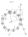
- Fig. 4 is a plan view of the conveyer unit 20 and a compression-forming machine 6
- Fig. 5 is a sectional view of a position where the molten resin from the conveyer unit 20 is handed over to the compression-forming machine 6.
- the apparatus 1 for feeding the molten resin which is a synthetic resin includes the extruder 2 of a cylindrical shape.
- the extruder 2 heats, melts and kneads the synthetic resin material such as polyethylene terephthalate (PET), and conveys the molten resin 11 to a gear pump 3.
- PET polyethylene terephthalate
- the gear pump 3 blows out the molten resin 11 by the mesh of the gears.
- the gear pump 3 is connected, through a pipe 2a, to the extrusion unit 4 that is downwardly directed as shown in Fig. 2 .
- the extrusion unit 4 has an extrusion opening 35c formed at a lower end portion thereof.
- the extrusion opening 35c has a circular shape in cross section, and the molten resin 11 is continuously extruded downward through the extrusion opening 35c being formed in nearly a cylindrical shape.
- the extruded molten resin 11 (drop) is cut by a cutter 12 and is separated away from the extrusion opening 35c.
- the molten resin 11 after cut is fed to a molten resin conveyer unit 20 in a transfer mechanism.
- the conveyer unit 20 opens and closes a holding unit 21 that holds the molten resin 11 so as to hold the molten resin 11 in its closed state and to downwardly discharge the molten resin 11 which it has held in its opened state.
- the holding unit 21 is allowed to move about the rotary shaft thereof.
- the molten resin 11 held by the holding unit 21 which is in the closed state is transferred to a position over a female mold 7 of the compression-forming machine 6. Thereafter, the holding unit 21 is opened, so that the molten resin 11 falls down due to the gravitational action, and is transferred into the female mold 7 shown in Figs. 4 and 5 .
- a preform from which a container will be obtained is formed by the female mold 7 and a male mold (not shown) of the compression-forming machine 6.
- Reference numeral 8 in Fig. 1 denotes a take-out mechanism for taking out the preform after having been formed.
- Fig. 2 is a sectional view of the extrusion unit 4 in the extruder on an enlarged scale.
- the extrusion unit 4 has an extrusion nozzle 30 attached to the lower portion of a cylindrical member 29.
- the extrusion unit 4 introduces the molten resin into the interior thereof and is forming a flow hole 29a of a circular shape in transverse cross section with its axis stretching up and down.
- a heater 31 is arranged surrounding the extrusion nozzle 30 to prevent the molten resin 11 passing through the flow hole 29a from being cooled.
- the heater 31 is surrounded by a support bracket 33 attached to the lower part of the cylindrical member 29.
- the support bracket 33 is nearly of a U-shape in its half cross section, i.e., of an annular shape with its open sides of U-shape being directed outward, and is supporting on its lower surface an air injection nozzle 35 that is connected to an air feed means 23 such as a pump (not shown) that feeds the air of normal temperature.
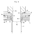
- An end nozzle 30a ( Fig. 6 is a view thereof of a further enlarged scale) is formed at the lower side of the position where the extrusion nozzle 30 is corresponded to the heater 31, and an end edge 30b at the lower end of the end nozzle 30a is formed at an acute angle like the edge of a knife.
- a micro-heater may be wound around this portion or a heater may be buried in this portion by casting.
- the air injection nozzle 35 is constituted by an annular upper plate 35a and an annular lower plate 35b arranged up and down, and is forming an air feed port 36 in an end portion thereof being connected to the air feed means 23.
- the air feed port 36 is forming an annular passage 37 surrounding the extrusion nozzle 30.
- the annular passage 37 extends aslant and downward on the inside in the radial direction of the annular air injection nozzle 35, and is communicated with an air injection passage 37a formed between the upper plate 35a and the lower plate 35b.
- An annular air injection port 37b is formed at the lower end of the air injection passage 37a.
- the air injection port 37b is positioned higher than the position of the end edge 30b of the extrusion nozzle 30. In other words, the end edge 30b of the extrusion nozzle 30 is arranged protruding downward beyond the air injection port 37b.
- the aslant angle of the air injection passage 37a must be such that the air injection passage 37a is directed to a position lower than the end edge 30b of the extrusion nozzle 30, so that the air injected from the air injection nozzle 35 is not blown to the end edge 30b but that the air is blown to the whole circumferential surface of the holding unit 21 which holds the molten resin and to which the molten resin 11 comes in contact.
- An annular gap 38 is formed between the end nozzle 30a of the extrusion nozzle 30 and the inner circumferential surface of the air injection nozzle 35.
- the extrusion unit 4 of the extruder 2 is so constituted as to move between the acting position (imaginary line) vertically over the locus of rotation of the holding unit 21 of the conveyer unit 20 and the non-acting position (solid line) retreated in a horizontal direction from the locus of rotation being driven by a drive source that is not shown.
- the conveyer unit 20 of the apparatus 1 for feeding the molten resin has a turntable 9.
- the turntable 9 is supported by a rotary shaft 9a having a vertical axis and is rotated clockwise in Fig. 4 by a drive source (not shown) such as an electric motor.
- the conveyer unit 20 is so conveyed as to pass through a position P1 opposed to the extrusion nozzle 30 to receive the molten resin 11, and a discharge position P2 opposed to the female mold 7 of the compression-formingmachine 6.
- the conveyer unit 20 is equipped with the cutter 12 for cutting the molten resin and the holding unit 21 for holding the molten resin.
- the cutter 12 is attached to a mounting portion 15 on the lower surface side of the turntable 9 of the conveyer unit 20. In a state where the cutter 12 is attached to the turntable 9, the blade tip 13 of the cutter 12 is so positioned as to horizontally protrude outward in the radial direction of the turn table 9 beyond the circumferential edge of the turntable 9.
- the blade tip 13 of the cutter 12 horizontally traverses just under the extrusion opening 35c maintaining a predetermined gap to thereby cut the molten resin 11 that is extruded vertically downward from the extrusion opening 35c.
- a shut-off valve 24 is provided between the air feed means 23 and the air feed port 36, and is opened and closed being controlled by a control unit 25.
- the control unit 25 Upon detecting the rotational angle of the cutter 12, the control unit 25 opens the shut-off valve 24 a predetermined rotational angle before the blade tip 13 of the cutter 12 cuts the molten resin 11 to inject the air onto the surface of the molten resin 11.
- the opening/closing degree of the shut-off valve 24, opening/closing time thereof and the timing for opening the shut-off valve 24 can be arbitrarily adjusted by the control unit 25.
- the holding unit 21 includes a first holding member 21a and a second holding member 21b.
- the holding members 21a and 21b are so constituted as to be opened and closed; i.e., the holding members 21a and 21b are closed at the position P1 opposed to the extrusion nozzle 30 for receiving the molten resin.
- Fig. 3 shows the holding members 21a and 21b in a state of holding the molten resin 11. At the position P2 for discharging the molten resin shown in Fig. 5 , the holding members 21a and 21b are opened permitting the molten resin 11 to fall down onto the female mold 7.
- the compression-formingmachine 6 is equipped with a rotary support member 6a and the forming molds inclusive of a plurality of female molds 7 arranged on the rotary support member 6a, and rotates counterclockwise as shown in Fig. 4 .
- the extrusion unit 4 of the extruder 2 shown in Fig. 1 is brought to the receiving position P1 shown in Figs. 3 and 4 . Due to the operation of the gear pump 3, the molten resin 11 is continuously extruded from the extrusion opening 35c. When the state of feeding the molten resin becomes stable, the molten resin 11 is fed onto the conveyer means.
- the control unit 25 instructs the shut-off valve 24 so as to be opened; i.e., the shut-off valve 24 is opened. Therefore, the air is fed with pressure from the air feed means 23 to the air feed port 36, passes through the annular passage 37, and is fed to the air injection passage 37a and to the air injection port 37b.
- the air is injected from the air injection port 37b onto the surface of the molten resin for a predetermined period of time; i.e., the air is blown onto the outer circumferential surface of the molten resin 11 as indicated by arrows A in Fig. 6 .
- the injected air blows off volatile components generated from the molten resin 11 so will not to deposit on the units which follow the cutting tool and, particularly, so will not to deposit on the surfaces of the holding members 21a, 21b of the holding unit 21.
- Adverse effect caused by the injection of the air is overcome in a manner as described below.
- the air injection passage 37a is directed to a position lower than the end edge 30b and, therefore, the end edge 30b is not cooled with the injected air.
- the injected air cools the surface only of the molten resin 11. Since the end edge 30b is not cooled, impurities do not deposit on the end edge 30b.
- the end edge 30b of the end nozzle 30b is so formed as to become thin toward the end, so that impurities are further prevented from depositing on the end edge 30b.
- the air injection nozzle 35 is arranged surrounding the end nozzle 30a of the extrusion nozzle 30 forming a gap 38 between the end nozzle 30a and the air injection nozzle 35.
- the air in the gap works as a heat-insulatingmaterial, and the end nozzle 30a is prevented from being cooled by the flow of the air.
- the air injected from the air injection nozzle 35 similarly works to prevent or suppress the rise of temperature caused by the heat of the molten resin 11.
- the adverse effect is prevented which otherwise is caused by the injection of the air onto the molten resin 11 extruded from the extrusion nozzle 30.
- the holding members 21a and 21b of the holding unit 21 hold the molten resin 11 (see Fig. 3 ).
- the turntable 9 of the conveyer unit 20 rotates in synchronism with the rotary support member 6a of the compression-formingmachine 6, which are driven by separate drive sources.
- the turntable 9 and the rotary support member 6a rotate in the directions opposite to each other, which, therefore, become the same at a contact point on the loci of rotation of the two. Therefore, a relatively static state is established at the exhaust position P2 at where the loci of rotation come in contact as the holding members 21a, 21b and the female mold 7 moves in synchronism.
- the holding state by the holding members 21a, 21b is released so that the molten resin 11 falls down so as to be fed into the female mold 7.
- a thin cooled film has been formed on the surface of the molten resin 11 having a temperature lower than the temperature on the inside thereof. Therefore, the molten resin 11 acquires a decreased viscosity, exhibits a decreased coefficient of friction to the surfaces of the holding members 21a, 21b, and is smoothly fed into the female mold 7.
- the apparatus for feeding the molten resin was operated under the following conditions in accordance with the present invention to measure the temperature on the surface of the molten resin and the number of times of feeding the molten resin.
- the molten resin extruded from the extrusion opening of the extruder was measured for its temperature on the surface thereof by using a radiation thermometer to be in a range of 250°C to 240°C.
- the apparatus for feeding the molten resin was cleaned and was continuously operated to measure the number of times of consecutive feeding per a set of the cutter 12 and the holding means 21 until the next cleaning became necessary.
- the molten resin (drop) could be consecutively fed up to about 10,000 to about 15,000 times.
- the material, amount of extrusion, diameter of the resin extrusion opening and the amount of extruding the molten resin were the same as those of the above Example.
- the molten resin was measured for its temperature on the surface thereof without blowing the air onto the surface of the molten resin, and the number of times of consecutively feeding the molten resin was measured in the same manner as in the above Example.
- the temperature on the surface of the molten resin was measured by using a radiation thermometer to be in a range of 288°C to 282°C.
- the number of times of consecutively feeding the molten resin from the apparatus for feeding the molten resin was measured to be about 2,000 to about 3,000 times before the cleaning of the next time was necessary.
- the Example of the present invention lowered the surface temperature of the molten resin by about 42°C to about 38°C and made it possible to increase the number of times of consecutively feeding the molten resin by about five folds.
- the gap 38 which is an annular space is formed as a heat-insulating member between the end nozzle 30a of the extrusion nozzle 30 and the inner peripheral surface of the air injection nozzle 35.
- a solid material having heat-insulating property may be arranged as a heat-insulating material to substitute for the air in the gap 38.
- the invention may be further applied to a feeding apparatus which continuously rotates but which is not of a circular motion of a constant radius to continuously inject the air during the operation.
- the above embodiment has used the air as the cooling fluid.
- the cooling fluid there can be also used, in addition to the air, an inert gas, the compressed air or the inert gas containing a liquid vapor.
- the molten resin is extruded from an extrusion opening of an extrusion nozzle, and the molten resin is cut with a cutting tool while injecting, or after having injected, the cooling fluid onto the surface portion of the molten resin maintaining a predetermined gap from the extrusion opening in a direction in which the molten resin is extruded. Therefore, the oligomer component and the high molecular PET on the surface of the molten resin are blown off with the fluid, or the surface of the molten resin is cooled to suppress the generation of the oligomer component and the high molecular PET.
- the molten resin just over the female mold is going to fall down into the female mold, no component has been deposited that impairs the slipping of the molten resin mass while the molten resin is being conveyed, and slipping property is maintained.
- the time for continuous operation can be lengthened for smoothly falling the molten resin from the holding member, and the operation efficiency of the apparatus can be increased.
- the apparatus for feeding a molten resin of the present invention comprises an extrusion nozzle for discharging the molten resin from an extrusion opening; a cutting tool for cutting the molten resin discharged from the extrusion opening of the extrusion nozzle; a holding member equipped with a mechanism for holding and releasing the molten resin discharged from the extrusion opening; and conveyer means for supporting the cutting tool and the holding member, and for conveying the holding member holding the molten resin after having been cut up to a female mold of a compression-forming metal mold; wherein the holding member releases the molten resin at a position over the female mold so as to be fed into the female mold; the apparatus for feeding a molten resin further comprising injection means for injecting a fluid to the surrounding of the extrusion nozzle, wherein an injection port of the injection means is directed to the surface of the molten resin maintaining a predetermined gap from the extrusion opening of the extrusion nozzle in a direction of extrusion of the extrusion nozzle,
- the injection means is provided in an annular shape to surround the extrusion nozzle, and a gap for insulating the heat is formed in an annular shape between the fluid feeding means and the extrusion nozzle. Therefore, the fluid from the injection means little receives the heat of the molten resin. Besides, the end of the extrusion nozzle is not very cooled by the fluid and, therefore, the molten resin can be blown maintaining stability, the volatile components on the surface of the molten resin after extruded are blown off and, besides, the surface of the extruded resin can be cooled.
- the above apparatus feeds the molten resin which is the polyester molten resin that easily deposits on the holding members.
- the present invention works to effectively decrease the deposition of matters on the holding portions.
Abstract
Description
- The present invention relates to an apparatus for feeding a molten resin which cuts the molten resin extruded from an extrusion opening of an extrusion nozzle by cutting means, holds the molten resin after cut by using holding means, and feeds the molten resin to a forming machine.
- Containers made of synthetic resin such as polyester have been widely put into practical use for containing beverages. Preforms from which synthetic resin containers are obtained by blow forming have, in recent years, been integrally formed by compression forming by using a compression-forming machine.
- In executing the compression forming, the synthetic resin in a molten state as extruded from an extrusion opening of an extrusion nozzle is fed (conveyed) into the compression-forming machine in a manner as described below.
- The molten resin is heated and melted in an extruder, and is extruded from the extrusion opening of the extrusion nozzle of the extruder. The molten resin that is extruded is cut by cutting means, and is separated away from the extrusion opening. The molten resin (molten resin to be cut) that is cut is fed onto molten resin conveyer means arranged in a transfer mechanism.
- The conveyer means is selectively set to a closed state where it holds the molten resin and to an opened state where it discharges the molten resin that is held to the down side, and further moves about the rotary shaft thereof. The molten resin received by the holding means which is in the closed state moves to a position over a female mold of the compression-forming machine. Thereafter, when the holding means is placed in the opened state, the molten resin is discharged (falls) downward so as to be transferred into the female mold.
- The molten resin transferred into the female mold is compression-formed by the cooperation with a male mold of the compression-forming machine, and is formed into a polyester preform of any desired shape for forming a beverage bottle or is formed into various products.
- Japanese Patent No.
3674337 - The present invention was accomplished in view of the above circumstances and has an object of providing an apparatus for feeding a molten resin, which can be operated for extended periods of time maintaining stability without permitting the volatile components to deposit on the surfaces of the conveyer means.
- The present invention was accomplished by giving attention to the following fact. That is, the apparatus for feeding a molten resin was cleaned with a solvent and, thereafter, the molten resin was consecutively fed and interrupted to analyze the total amount of deposit on the portions that held the molten resin. In this case, the amount of the oligomer component was 0.1 to 0.15 µg and the amount of the high molecular PET component was about 0.15 µg per the cut and conveyance of the molten resin of each time. On the other hand, when the air was blown with a pressure of 0.1 MPa onto the molten resin, the amount of the oligomer component decreased down to 0.04 to 0.05 µg and the amount of the high molecular PET component decreased down to 0.003 µg per the cut and conveyance of the molten resin of each time.
- In order to achieve the above object, an apparatus for feeding a molten resin of the present invention for forming a beverage bottle comprises an extrusion nozzle for discharging the molten resin from an extrusion opening; a cutting tool for cutting the molten resin discharged from the extrusion opening of the extrusion nozzle; a holding member equipped with a mechanism for holding and releasing the molten resin discharged from the extrusion opening; and conveyer means for supporting the cutting tool and the holding member, and for conveying the holding member holding the molten resin after having been cut up to a female mold of a compression-forming metal mold; wherein the holding member is suitable for releasing the molten resin at a position over the female mold so as to be fed into the female mold; the apparatus for feeding a molten resin further comprising injection means for injecting gas or a gaseous substance to the surrounding of the extrusion nozzle, wherein an injection port of the injection means, which is provided in an annular shape to surround the extrusion nozzle, is directed to the surface of the molten resin maintaining a predetermined gap from the extrusion opening of the extrusion nozzle in a direction of extrusion of the extrusion nozzle and the gas or gaseous substance is blown onto the molten resin extruded from the extrusion opening, and the molten resin of which the surface is cooled with the gas or gaseous substance is held by the holding member.
- In the above apparatus for feeding a molten resin, the injection means is provided in an annular shape to surround the extrusion nozzle, and a gap for insulating the heat is formed in an annular shape between the fluid feeding means and the extrusion nozzle.
- Further, the above apparatus for feeding a molten resin becomes more effective if the molten resin is a molten resin of polyester.
-
-
Fig. 1 is a plan view schematically illustrating an apparatus for feeding a molten resin according to an embodiment of the present invention; -
Fig. 2 is a sectional view of an extrusion unit in an extrusion-forming machine using the apparatus for feeding a molten resin ofFig. 1 ; -
Fig. 3 is a sectional view of a state where a holding member of conveyer means in the apparatus for feeding a molten resin ofFig. 1 is closed; -
Fig. 4 is a plan view of conveyer means in the apparatus for feeding a molten resin ofFig. 1 ; -
Fig. 5 is a sectional view of a state where the holding member of conveyer means in the apparatus for feeding a molten resin ofFig. 1 is opened; and -
Fig. 6 is a sectional view illustrating, on an enlarged scale, an extrusion nozzle of the extrusion unit in the extrusion-forming machine ofFig. 2 . - The apparatus for feeding a molten resin according to an embodiment of the invention will now be described with reference to the drawings.
-
Fig. 1 is a view of anapparatus 1 for feeding a molten resin according to the present invention and a compression-formingmachine 6 according to the present invention,Fig. 2 is a view illustrating, on an enlarged scale, anextrusion unit 4 in anextruder 2 which uses the apparatus for feeding the synthetic resin,Fig. 3 is a sectional view of a position where the molten resin from theextrusion unit 4 is handed over to aconveyer unit 20,Fig. 4 is a plan view of theconveyer unit 20 and a compression-formingmachine 6, andFig. 5 is a sectional view of a position where the molten resin from theconveyer unit 20 is handed over to the compression-formingmachine 6. - First, briefly described below is a flow of a
molten resin 11 formed by the extruder 2 (seeFig. 2 ). - The
apparatus 1 for feeding the molten resin which is a synthetic resin includes theextruder 2 of a cylindrical shape. The extruder 2 heats, melts and kneads the synthetic resin material such as polyethylene terephthalate (PET), and conveys themolten resin 11 to agear pump 3. To feed themolten resin 11 maintaining stability, thegear pump 3 blows out themolten resin 11 by the mesh of the gears. Thegear pump 3 is connected, through apipe 2a, to theextrusion unit 4 that is downwardly directed as shown inFig. 2 . Theextrusion unit 4 has an extrusion opening 35c formed at a lower end portion thereof. The extrusion opening 35c has a circular shape in cross section, and themolten resin 11 is continuously extruded downward through the extrusion opening 35c being formed in nearly a cylindrical shape. - Referring to
Fig. 3 , the extruded molten resin 11 (drop) is cut by acutter 12 and is separated away from the extrusion opening 35c. Themolten resin 11 after cut is fed to a moltenresin conveyer unit 20 in a transfer mechanism. - The
conveyer unit 20 opens and closes aholding unit 21 that holds themolten resin 11 so as to hold themolten resin 11 in its closed state and to downwardly discharge themolten resin 11 which it has held in its opened state. Theholding unit 21 is allowed to move about the rotary shaft thereof. Themolten resin 11 held by theholding unit 21 which is in the closed state is transferred to a position over afemale mold 7 of the compression-formingmachine 6. Thereafter, theholding unit 21 is opened, so that themolten resin 11 falls down due to the gravitational action, and is transferred into thefemale mold 7 shown inFigs. 4 and5 . A preform from which a container will be obtained is formed by thefemale mold 7 and a male mold (not shown) of the compression-formingmachine 6. -
Reference numeral 8 inFig. 1 denotes a take-out mechanism for taking out the preform after having been formed. -
Fig. 2 is a sectional view of theextrusion unit 4 in the extruder on an enlarged scale. - The
extrusion unit 4 has anextrusion nozzle 30 attached to the lower portion of acylindrical member 29. Theextrusion unit 4 introduces the molten resin into the interior thereof and is forming aflow hole 29a of a circular shape in transverse cross section with its axis stretching up and down. Aheater 31 is arranged surrounding theextrusion nozzle 30 to prevent themolten resin 11 passing through theflow hole 29a from being cooled. Theheater 31 is surrounded by asupport bracket 33 attached to the lower part of thecylindrical member 29. Thesupport bracket 33 is nearly of a U-shape in its half cross section, i.e., of an annular shape with its open sides of U-shape being directed outward, and is supporting on its lower surface anair injection nozzle 35 that is connected to an air feed means 23 such as a pump (not shown) that feeds the air of normal temperature. - An
end nozzle 30a (Fig. 6 is a view thereof of a further enlarged scale) is formed at the lower side of the position where theextrusion nozzle 30 is corresponded to theheater 31, and anend edge 30b at the lower end of theend nozzle 30a is formed at an acute angle like the edge of a knife. As required, a micro-heater may be wound around this portion or a heater may be buried in this portion by casting. - The
air injection nozzle 35 is constituted by an annularupper plate 35a and an annularlower plate 35b arranged up and down, and is forming anair feed port 36 in an end portion thereof being connected to the air feed means 23. Theair feed port 36 is forming anannular passage 37 surrounding theextrusion nozzle 30. Referring toFig. 6 , theannular passage 37 extends aslant and downward on the inside in the radial direction of the annularair injection nozzle 35, and is communicated with anair injection passage 37a formed between theupper plate 35a and thelower plate 35b. An annularair injection port 37b is formed at the lower end of theair injection passage 37a. Theair injection port 37b is positioned higher than the position of theend edge 30b of theextrusion nozzle 30. In other words, theend edge 30b of theextrusion nozzle 30 is arranged protruding downward beyond theair injection port 37b. - The aslant angle of the
air injection passage 37a must be such that theair injection passage 37a is directed to a position lower than theend edge 30b of theextrusion nozzle 30, so that the air injected from theair injection nozzle 35 is not blown to theend edge 30b but that the air is blown to the whole circumferential surface of the holdingunit 21 which holds the molten resin and to which themolten resin 11 comes in contact. Anannular gap 38 is formed between theend nozzle 30a of theextrusion nozzle 30 and the inner circumferential surface of theair injection nozzle 35. - Referring to
Fig. 1 , theextrusion unit 4 of theextruder 2 is so constituted as to move between the acting position (imaginary line) vertically over the locus of rotation of the holdingunit 21 of theconveyer unit 20 and the non-acting position (solid line) retreated in a horizontal direction from the locus of rotation being driven by a drive source that is not shown. - Referring to
Figs. 3 to 5 , theconveyer unit 20 of theapparatus 1 for feeding the molten resin has aturntable 9. Theturntable 9 is supported by arotary shaft 9a having a vertical axis and is rotated clockwise inFig. 4 by a drive source (not shown) such as an electric motor. Theconveyer unit 20 is so conveyed as to pass through a position P1 opposed to theextrusion nozzle 30 to receive themolten resin 11, and a discharge position P2 opposed to thefemale mold 7 of the compression-formingmachine 6. Theconveyer unit 20 is equipped with thecutter 12 for cutting the molten resin and the holdingunit 21 for holding the molten resin. - The
cutter 12 is attached to a mountingportion 15 on the lower surface side of theturntable 9 of theconveyer unit 20. In a state where thecutter 12 is attached to theturntable 9, theblade tip 13 of thecutter 12 is so positioned as to horizontally protrude outward in the radial direction of the turn table 9 beyond the circumferential edge of theturntable 9. - Therefore, as the
molten resin 11 is extruded from theextrusion opening 35c of theextrusion nozzle 30 and as theturntable 9 is rotated, theblade tip 13 of thecutter 12 horizontally traverses just under theextrusion opening 35c maintaining a predetermined gap to thereby cut themolten resin 11 that is extruded vertically downward from theextrusion opening 35c. - Referring to
Fig. 2 , a shut-offvalve 24 is provided between the air feed means 23 and theair feed port 36, and is opened and closed being controlled by acontrol unit 25. Upon detecting the rotational angle of thecutter 12, thecontrol unit 25 opens the shut-off valve 24 a predetermined rotational angle before theblade tip 13 of thecutter 12 cuts themolten resin 11 to inject the air onto the surface of themolten resin 11. The opening/closing degree of the shut-offvalve 24, opening/closing time thereof and the timing for opening the shut-offvalve 24 can be arbitrarily adjusted by thecontrol unit 25. - The holding
unit 21 includes a first holdingmember 21a and asecond holding member 21b. The holdingmembers members extrusion nozzle 30 for receiving the molten resin.Fig. 3 shows the holdingmembers molten resin 11. At the position P2 for discharging the molten resin shown inFig. 5 , the holdingmembers molten resin 11 to fall down onto thefemale mold 7. - The compression-
formingmachine 6 is equipped with arotary support member 6a and the forming molds inclusive of a plurality offemale molds 7 arranged on therotary support member 6a, and rotates counterclockwise as shown inFig. 4 . - Operation of this embodiment will be described below.
- In feeding the
molten resin 11 in the forming operation, first, theextrusion unit 4 of theextruder 2 shown inFig. 1 is brought to the receiving position P1 shown inFigs. 3 and4 . Due to the operation of thegear pump 3, themolten resin 11 is continuously extruded from theextrusion opening 35c. When the state of feeding the molten resin becomes stable, themolten resin 11 is fed onto the conveyer means. - Referring to
Fig. 2 , as themolten resin 11 is extruded from theextrusion opening 35c and thecutter 12 comes to a predetermined position, thecontrol unit 25 instructs the shut-offvalve 24 so as to be opened; i.e., the shut-offvalve 24 is opened. Therefore, the air is fed with pressure from the air feed means 23 to theair feed port 36, passes through theannular passage 37, and is fed to theair injection passage 37a and to theair injection port 37b. The air is injected from theair injection port 37b onto the surface of the molten resin for a predetermined period of time; i.e., the air is blown onto the outer circumferential surface of themolten resin 11 as indicated by arrows A inFig. 6 . The injected air blows off volatile components generated from themolten resin 11 so will not to deposit on the units which follow the cutting tool and, particularly, so will not to deposit on the surfaces of the holdingmembers unit 21. - Adverse effect caused by the injection of the air is overcome in a manner as described below. The
air injection passage 37a is directed to a position lower than theend edge 30b and, therefore, theend edge 30b is not cooled with the injected air. The injected air cools the surface only of themolten resin 11. Since theend edge 30b is not cooled, impurities do not deposit on theend edge 30b. Theend edge 30b of theend nozzle 30b is so formed as to become thin toward the end, so that impurities are further prevented from depositing on theend edge 30b. - In the
extrusion unit 4, theair injection nozzle 35 is arranged surrounding theend nozzle 30a of theextrusion nozzle 30 forming agap 38 between theend nozzle 30a and theair injection nozzle 35. The air in the gap works as a heat-insulatingmaterial, and theend nozzle 30a is prevented from being cooled by the flow of the air. The air injected from theair injection nozzle 35 similarly works to prevent or suppress the rise of temperature caused by the heat of themolten resin 11. Thus, the adverse effect is prevented which otherwise is caused by the injection of the air onto themolten resin 11 extruded from theextrusion nozzle 30. - As the
cutter 12 cuts themolten resin 11 accompanying the rotation of theconveyer unit 20, the holdingmembers unit 21 hold the molten resin 11 (seeFig. 3 ). Theturntable 9 of theconveyer unit 20 rotates in synchronism with therotary support member 6a of the compression-formingmachine 6, which are driven by separate drive sources. - Referring to
Fig. 4 or5 , theturntable 9 and therotary support member 6a rotate in the directions opposite to each other, which, therefore, become the same at a contact point on the loci of rotation of the two. Therefore, a relatively static state is established at the exhaust position P2 at where the loci of rotation come in contact as the holdingmembers female mold 7 moves in synchronism. When themolten resin 11 is brought to just over thefemale mold 7, therefore, the holding state by the holdingmembers molten resin 11 falls down so as to be fed into thefemale mold 7. At this moment, a thin cooled film has been formed on the surface of themolten resin 11 having a temperature lower than the temperature on the inside thereof. Therefore, themolten resin 11 acquires a decreased viscosity, exhibits a decreased coefficient of friction to the surfaces of the holdingmembers female mold 7. - As described above, matters such as oligomer and high molecular PET deposit less on the holding
members apparatus 1 is continuously operated for feeding the molten resin, a delay in the timing for falling themolten resin 11 onto thefemale mold 7 by releasing the holdingmembers molten resin 11 into thefemale molds 7 for extended periods of time maintaining stability, to continuously produce the preforms, to decrease the frequency for cleaning the holdingunits 21 and to improve the operation efficiency of theapparatus 1 for feeding the molten resin. - In the compression-forming
machine 6 shown inFig. 1 , as thefemale mold 7 that has received themolten resin 11 arrives at a predetermined position accompanying the rotation of therotary support member 6a, a male mold (not shown) disposed vertically over thefemale mold 7 starts descending to commence the compression forming which is completed at a predetermined position on the downstream side. Thus, the operation of theapparatus 1 is repeated for feeding the molten resin. - The apparatus for feeding the molten resin was operated under the following conditions in accordance with the present invention to measure the temperature on the surface of the molten resin and the number of times of feeding the molten resin.
- Material: PET
- Amount of extrusion: 300 kg/hour
- Diameter of resin extrusion opening: 20 mm
- Gap of air injection portion: 0.6 mm
- Diameter of air blow portion: 23 mm
- Air feed pressure: 0.1 MPa
- Amount of extruding the molten resin (drop): 25 g
- The molten resin extruded from the extrusion opening of the extruder was measured for its temperature on the surface thereof by using a radiation thermometer to be in a range of 250°C to 240°C.
- The apparatus for feeding the molten resin was cleaned and was continuously operated to measure the number of times of consecutive feeding per a set of the
cutter 12 and the holding means 21 until the next cleaning became necessary. The molten resin (drop) could be consecutively fed up to about 10,000 to about 15,000 times. - The material, amount of extrusion, diameter of the resin extrusion opening and the amount of extruding the molten resin were the same as those of the above Example. The molten resin was measured for its temperature on the surface thereof without blowing the air onto the surface of the molten resin, and the number of times of consecutively feeding the molten resin was measured in the same manner as in the above Example.
The temperature on the surface of the molten resin was measured by using a radiation thermometer to be in a range of 288°C to 282°C. - Further, the number of times of consecutively feeding the molten resin from the apparatus for feeding the molten resin was measured to be about 2,000 to about 3,000 times before the cleaning of the next time was necessary.
- As compared to the Comparative Example, the Example of the present invention lowered the surface temperature of the molten resin by about 42°C to about 38°C and made it possible to increase the number of times of consecutively feeding the molten resin by about five folds.
- Though an embodiment of the invention was described above, it should be noted that the invention can be varied or modified in a variety of other ways without departing from the technical scope of the invention as defined by the appended claims.
- In the above embodiment, for example, the
gap 38 which is an annular space is formed as a heat-insulating member between theend nozzle 30a of theextrusion nozzle 30 and the inner peripheral surface of theair injection nozzle 35. A solid material having heat-insulating property may be arranged as a heat-insulating material to substitute for the air in thegap 38. The invention may be further applied to a feeding apparatus which continuously rotates but which is not of a circular motion of a constant radius to continuously inject the air during the operation. - The above embodiment has used the air as the cooling fluid. As the cooling fluid, however, there can be also used, in addition to the air, an inert gas, the compressed air or the inert gas containing a liquid vapor.
- According to the invention, the molten resin is extruded from an extrusion opening of an extrusion nozzle, and the molten resin is cut with a cutting tool while injecting, or after having injected, the cooling fluid onto the surface portion of the molten resin maintaining a predetermined gap from the extrusion opening in a direction in which the molten resin is extruded. Therefore, the oligomer component and the high molecular PET on the surface of the molten resin are blown off with the fluid, or the surface of the molten resin is cooled to suppress the generation of the oligomer component and the high molecular PET. The oligomer component and the high molecular PET deposit or are transferred little onto the tools used in the steps after the step of using the cutting tool for cutting the molten resin. Therefore, the molten resin that is cut can be held and conveyed up to the female mold of the compression-forming metal mold. When the molten resin just over the female mold is going to fall down into the female mold, no component has been deposited that impairs the slipping of the molten resin mass while the molten resin is being conveyed, and slipping property is maintained. As a result, the time for continuous operation can be lengthened for smoothly falling the molten resin from the holding member, and the operation efficiency of the apparatus can be increased.
- The apparatus for feeding a molten resin of the present invention comprises an extrusion nozzle for discharging the molten resin from an extrusion opening; a cutting tool for cutting the molten resin discharged from the extrusion opening of the extrusion nozzle; a holding member equipped with a mechanism for holding and releasing the molten resin discharged from the extrusion opening; and conveyer means for supporting the cutting tool and the holding member, and for conveying the holding member holding the molten resin after having been cut up to a female mold of a compression-forming metal mold; wherein the holding member releases the molten resin at a position over the female mold so as to be fed into the female mold; the apparatus for feeding a molten resin further comprising injection means for injecting a fluid to the surrounding of the extrusion nozzle, wherein an injection port of the injection means is directed to the surface of the molten resin maintaining a predetermined gap from the extrusion opening of the extrusion nozzle in a direction of extrusion of the extrusion nozzle, and the molten resin of which the surface is cooled with the fluid is held by the holding member.
By forming a thin cooled film on the surface of the molten resin having a temperature different from the temperature in the interior thereof, matters deposit little on the members for holding the molten resin in the conveyer means. Since matters deposit little on the conveyer means, the molten resin can be smoothly fed for extended periods of time when it is going to be fallen down into the female mold of the compression-forming machine. As a result, the operation efficiency of the apparatus for feeding the molten resin can be improved. - In the apparatus for feeding the molten resin, the injection means is provided in an annular shape to surround the extrusion nozzle, and a gap for insulating the heat is formed in an annular shape between the fluid feeding means and the extrusion nozzle. Therefore, the fluid from the injection means little receives the heat of the molten resin. Besides, the end of the extrusion nozzle is not very cooled by the fluid and, therefore, the molten resin can be blown maintaining stability, the volatile components on the surface of the molten resin after extruded are blown off and, besides, the surface of the extruded resin can be cooled.
- Further, the above apparatus feeds the molten resin which is the polyester molten resin that easily deposits on the holding members. Here, the present invention works to effectively decrease the deposition of matters on the holding portions.
Claims (4)
- An apparatus (1) for feeding a molten resin (11) for forming a beverage bottle, comprising:an extrusion nozzle (30) for discharging the molten resin (11) from an extrusion opening (35c);acuttingtool (12) for cutting the molten resin discharged from the extrusion opening of said extrusion nozzle;a holding member (21) equipped with a mechanism for holding and releasing the molten resin discharged from said extrusion opening; andconveyer means (20) for supporting said cutting tool (12) and said holding member (21), and for conveying said holding member holding the molten resin after having been cut up to a female mold (7) of a compression-forming metal mold (6); whereinsaid holding member (21) being suitable for releasing the molten resin (11) at a position over said female mold (7) so as to be fed into said female mold;said apparatus for feeding a molten resin further comprising injection means (35) for injecting gas or a gaseous substance to the surrounding of said extrusion nozzle (30), wherein an injection port (37b) of said injection means, which is provided in an annular shape to surround the extrusion nozzle, is directed to the surface of the molten resin maintaining a predetermined gap (38) from said extrusion opening (35c) of said extrusion nozzle (30) in a direction of extrusion of said extrusion nozzle and the gas or gaseous substance is blown onto the molten resin extruded from the extrusion opening, and the molten resin of which the surface is cooled with the gas or gaseous substance is held by said holding member (21).
- The apparatus for feeding a molten resin according to claim 1, wherein a gap (38) for insulating the heat is formed in an annular shape between said gas or gaseous substance feeding means and said extrusion nozzle (30).
- The apparatus for feeding a molten resin according to claim 1 or 2, wherein said molten resin (11) is a molten resin of a polyester.
- The apparatus for feeding a molten resin according to any of claims 1 to 3, wherein the gas or gaseous substance is blown onto a portion, which is to come in contact with the holding unit, of the outer circumferential surface of the molten resin extruded from the extrusion opening.
Applications Claiming Priority (2)
| Application Number | Priority Date | Filing Date | Title |
|---|---|---|---|
| JP2006051659A JP4725362B2 (en) | 2006-02-28 | 2006-02-28 | Molten resin supply method and molten resin supply apparatus |
| PCT/JP2007/053460 WO2007105464A1 (en) | 2006-02-28 | 2007-02-20 | Molten resin supply method and molten resin supply device |
Publications (3)
| Publication Number | Publication Date |
|---|---|
| EP1990171A1 EP1990171A1 (en) | 2008-11-12 |
| EP1990171A4 EP1990171A4 (en) | 2010-06-02 |
| EP1990171B1 true EP1990171B1 (en) | 2012-07-04 |
Family
ID=38509300
Family Applications (1)
| Application Number | Title | Priority Date | Filing Date |
|---|---|---|---|
| EP07708425A Expired - Fee Related EP1990171B1 (en) | 2006-02-28 | 2007-02-20 | Apparatus for feeding molten resin |
Country Status (5)
| Country | Link |
|---|---|
| US (1) | US7776245B2 (en) |
| EP (1) | EP1990171B1 (en) |
| JP (1) | JP4725362B2 (en) |
| CN (1) | CN101389460B (en) |
| WO (1) | WO2007105464A1 (en) |
Families Citing this family (5)
| Publication number | Priority date | Publication date | Assignee | Title |
|---|---|---|---|---|
| US8911225B2 (en) | 2007-10-24 | 2014-12-16 | Toyo Seikan Kaisha, Ltd. | Compression-molding apparatus and compression-molding method |
| JP5023964B2 (en) * | 2007-10-24 | 2012-09-12 | 東洋製罐株式会社 | Compression molding equipment |
| JP5151566B2 (en) * | 2008-03-07 | 2013-02-27 | 東洋製罐株式会社 | A compression molding apparatus provided with a cutter for cutting a molten resin used for compression molding. |
| EP2684667B1 (en) | 2011-03-10 | 2017-05-31 | Toyo Seikan Group Holdings, Ltd. | System and method for feeding molten resin |
| CN117227130A (en) * | 2023-11-16 | 2023-12-15 | 雅安市兴元塑料制品有限公司 | Continuous forming equipment for processing fiber reinforced pipe |
Family Cites Families (11)
| Publication number | Priority date | Publication date | Assignee | Title |
|---|---|---|---|---|
| DE2836941A1 (en) | 1978-08-24 | 1980-03-13 | Walter Goern | Additional cooling for hollow extrusions - where compressed gas emerges from nozzle and cools by expansion within extrusions before escaping |
| DE3804464C1 (en) * | 1988-02-12 | 1989-06-08 | Aisa Automation Industrielle S.A., Vouvry, Ch | |
| JPH05293799A (en) | 1992-04-20 | 1993-11-09 | Japan Steel Works Ltd:The | Jet stream cutting method and device |
| JP2595867B2 (en) * | 1992-12-28 | 1997-04-02 | 株式会社新潟鉄工所 | Injection device for resin in injection compression molding machine |
| JP3674337B2 (en) * | 1998-10-02 | 2005-07-20 | 東洋製罐株式会社 | Synthetic resin feeder |
| US6349838B1 (en) * | 1998-12-25 | 2002-02-26 | Toyo Seikan Kaisha, Ltd. | Plastic bottle and method of producing the same |
| JP2002103428A (en) * | 2000-09-29 | 2002-04-09 | Toyo Seikan Kaisha Ltd | Multilayered preform and multilayered bottle manufactured using the same |
| ITRE20030012A1 (en) * | 2003-01-31 | 2004-08-01 | Sacmi | "DOSE SEPARATION AND TRANSPORTATION DEVICE |
| JP4042596B2 (en) * | 2003-03-14 | 2008-02-06 | 東洋製罐株式会社 | Synthetic resin feeder |
| JP4340853B2 (en) | 2003-04-11 | 2009-10-07 | 東洋製罐株式会社 | Compression molding method for hollow multilayer resin molded product |
| ITRE20040040A1 (en) | 2004-04-23 | 2004-07-23 | Sacmi | METHOD AND EQUIPMENT FOR TRANSFERRING DOSED BODIES OF POLYMERIC MATERIAL TO THE DIE CAVITY OF A MOLDING MACHINE |
-
2006
- 2006-02-28 JP JP2006051659A patent/JP4725362B2/en not_active Expired - Fee Related
-
2007
- 2007-02-20 CN CN2007800068962A patent/CN101389460B/en not_active Expired - Fee Related
- 2007-02-20 US US12/281,037 patent/US7776245B2/en not_active Expired - Fee Related
- 2007-02-20 WO PCT/JP2007/053460 patent/WO2007105464A1/en active Application Filing
- 2007-02-20 EP EP07708425A patent/EP1990171B1/en not_active Expired - Fee Related
Also Published As
| Publication number | Publication date |
|---|---|
| JP2007229981A (en) | 2007-09-13 |
| EP1990171A1 (en) | 2008-11-12 |
| CN101389460B (en) | 2012-04-18 |
| US20090236767A1 (en) | 2009-09-24 |
| US7776245B2 (en) | 2010-08-17 |
| WO2007105464A1 (en) | 2007-09-20 |
| JP4725362B2 (en) | 2011-07-13 |
| EP1990171A4 (en) | 2010-06-02 |
| CN101389460A (en) | 2009-03-18 |
Similar Documents
| Publication | Publication Date | Title |
|---|---|---|
| EP1990171B1 (en) | Apparatus for feeding molten resin | |
| US8007266B2 (en) | Compression moulding apparatus | |
| JP4573175B2 (en) | Method and apparatus for forcibly inserting a drop into a compression molding machine, and molding die follow-up type drop supply method and apparatus | |
| JP3674337B2 (en) | Synthetic resin feeder | |
| EP2206592B1 (en) | Compression-molding apparatus | |
| CN106414012B (en) | Method and device for applying annular shaped objects | |
| EP2436497A1 (en) | Apparatus for compression moulding plastics articles | |
| WO2005102646A1 (en) | Machine and method for transferring melted polymeric material bodies | |
| US9180611B2 (en) | Compression-forming system | |
| EP2193905B1 (en) | Apparatus for feeding molten resin | |
| EP2279051A2 (en) | Plant and apparatus for forming crown caps | |
| JP4670422B2 (en) | Compression molding method | |
| JP5572034B2 (en) | Method and apparatus for producing hollow extruded product using thermoplastic resin | |
| KR20020039668A (en) | Apparatus for manufacturing biodegradable plant fibre products | |
| AU2005235002A1 (en) | Apparatuses and method for transferring plastics material to a compression moulding machine |
Legal Events
| Date | Code | Title | Description |
|---|---|---|---|
| PUAI | Public reference made under article 153(3) epc to a published international application that has entered the european phase |
Free format text: ORIGINAL CODE: 0009012 |
|
| 17P | Request for examination filed |
Effective date: 20080821 |
|
| AK | Designated contracting states |
Kind code of ref document: A1 Designated state(s): DE FR GB IT |
|
| RBV | Designated contracting states (corrected) |
Designated state(s): DE FR GB IT |
|
| RIC1 | Information provided on ipc code assigned before grant |
Ipc: B29C 47/88 20060101ALI20100407BHEP Ipc: B29K 67/00 20060101ALI20100407BHEP Ipc: B29B 11/10 20060101ALI20100407BHEP Ipc: B29C 31/04 20060101ALI20100407BHEP Ipc: B29C 43/08 20060101ALI20100407BHEP Ipc: B29C 69/00 20060101ALN20100407BHEP Ipc: B29C 43/34 20060101AFI20071008BHEP |
|
| A4 | Supplementary search report drawn up and despatched |
Effective date: 20100503 |
|
| 17Q | First examination report despatched |
Effective date: 20100723 |
|
| RIC1 | Information provided on ipc code assigned before grant |
Ipc: B29C 31/04 20060101ALI20110913BHEP Ipc: B29K 67/00 20060101ALI20110913BHEP Ipc: B29B 11/10 20060101ALI20110913BHEP Ipc: B29C 69/00 20060101ALN20110913BHEP Ipc: B29C 43/34 20060101AFI20110913BHEP Ipc: B29C 43/08 20060101ALI20110913BHEP Ipc: B29C 47/88 20060101ALI20110913BHEP |
|
| RTI1 | Title (correction) |
Free format text: APPARATUS FOR FEEDING MOLTEN RESIN |
|
| GRAP | Despatch of communication of intention to grant a patent |
Free format text: ORIGINAL CODE: EPIDOSNIGR1 |
|
| RIC1 | Information provided on ipc code assigned before grant |
Ipc: B29C 47/88 20060101ALI20120208BHEP Ipc: B29K 67/00 20060101ALI20120208BHEP Ipc: B29C 31/04 20060101ALI20120208BHEP Ipc: B29C 69/00 20060101ALN20120208BHEP Ipc: B29C 43/34 20060101AFI20120208BHEP Ipc: B29C 43/08 20060101ALI20120208BHEP Ipc: B29B 11/10 20060101ALI20120208BHEP |
|
| DAX | Request for extension of the european patent (deleted) | ||
| GRAS | Grant fee paid |
Free format text: ORIGINAL CODE: EPIDOSNIGR3 |
|
| GRAA | (expected) grant |
Free format text: ORIGINAL CODE: 0009210 |
|
| AK | Designated contracting states |
Kind code of ref document: B1 Designated state(s): DE FR GB IT |
|
| REG | Reference to a national code |
Ref country code: GB Ref legal event code: FG4D |
|
| REG | Reference to a national code |
Ref country code: DE Ref legal event code: R096 Ref document number: 602007023789 Country of ref document: DE Effective date: 20120830 |
|
| PLBE | No opposition filed within time limit |
Free format text: ORIGINAL CODE: 0009261 |
|
| STAA | Information on the status of an ep patent application or granted ep patent |
Free format text: STATUS: NO OPPOSITION FILED WITHIN TIME LIMIT |
|
| 26N | No opposition filed |
Effective date: 20130405 |
|
| REG | Reference to a national code |
Ref country code: DE Ref legal event code: R097 Ref document number: 602007023789 Country of ref document: DE Effective date: 20130405 |
|
| REG | Reference to a national code |
Ref country code: FR Ref legal event code: PLFP Year of fee payment: 10 |
|
| REG | Reference to a national code |
Ref country code: FR Ref legal event code: PLFP Year of fee payment: 11 |
|
| REG | Reference to a national code |
Ref country code: FR Ref legal event code: PLFP Year of fee payment: 12 |
|
| PGFP | Annual fee paid to national office [announced via postgrant information from national office to epo] |
Ref country code: GB Payment date: 20190218 Year of fee payment: 13 Ref country code: IT Payment date: 20190225 Year of fee payment: 13 Ref country code: DE Payment date: 20190219 Year of fee payment: 13 |
|
| PGFP | Annual fee paid to national office [announced via postgrant information from national office to epo] |
Ref country code: FR Payment date: 20190220 Year of fee payment: 13 Ref country code: DE Payment date: 20190219 Year of fee payment: 13 |
|
| REG | Reference to a national code |
Ref country code: DE Ref legal event code: R119 Ref document number: 602007023789 Country of ref document: DE |
|
| GBPC | Gb: european patent ceased through non-payment of renewal fee |
Effective date: 20200220 |
|
| PG25 | Lapsed in a contracting state [announced via postgrant information from national office to epo] |
Ref country code: FR Free format text: LAPSE BECAUSE OF NON-PAYMENT OF DUE FEES Effective date: 20200229 Ref country code: GB Free format text: LAPSE BECAUSE OF NON-PAYMENT OF DUE FEES Effective date: 20200220 Ref country code: DE Free format text: LAPSE BECAUSE OF NON-PAYMENT OF DUE FEES Effective date: 20200901 |
|
| PG25 | Lapsed in a contracting state [announced via postgrant information from national office to epo] |
Ref country code: IT Free format text: LAPSE BECAUSE OF NON-PAYMENT OF DUE FEES Effective date: 20200220 |