EP1990026A2 - Partial humeral head prosthesis - Google Patents
Partial humeral head prosthesis Download PDFInfo
- Publication number
- EP1990026A2 EP1990026A2 EP08251602A EP08251602A EP1990026A2 EP 1990026 A2 EP1990026 A2 EP 1990026A2 EP 08251602 A EP08251602 A EP 08251602A EP 08251602 A EP08251602 A EP 08251602A EP 1990026 A2 EP1990026 A2 EP 1990026A2
- Authority
- EP
- European Patent Office
- Prior art keywords
- humeral head
- partial
- prosthetic
- prosthesis
- head prosthesis
- Prior art date
- Legal status (The legal status is an assumption and is not a legal conclusion. Google has not performed a legal analysis and makes no representation as to the accuracy of the status listed.)
- Granted
Links
Images





Classifications
-
- A—HUMAN NECESSITIES
- A61—MEDICAL OR VETERINARY SCIENCE; HYGIENE
- A61F—FILTERS IMPLANTABLE INTO BLOOD VESSELS; PROSTHESES; DEVICES PROVIDING PATENCY TO, OR PREVENTING COLLAPSING OF, TUBULAR STRUCTURES OF THE BODY, e.g. STENTS; ORTHOPAEDIC, NURSING OR CONTRACEPTIVE DEVICES; FOMENTATION; TREATMENT OR PROTECTION OF EYES OR EARS; BANDAGES, DRESSINGS OR ABSORBENT PADS; FIRST-AID KITS
- A61F2/00—Filters implantable into blood vessels; Prostheses, i.e. artificial substitutes or replacements for parts of the body; Appliances for connecting them with the body; Devices providing patency to, or preventing collapsing of, tubular structures of the body, e.g. stents
- A61F2/02—Prostheses implantable into the body
- A61F2/30—Joints
- A61F2/40—Joints for shoulders
- A61F2/4003—Replacing only the epiphyseal or metaphyseal parts of the humerus, i.e. endoprosthesis not comprising an entire humeral shaft
-
- A—HUMAN NECESSITIES
- A61—MEDICAL OR VETERINARY SCIENCE; HYGIENE
- A61B—DIAGNOSIS; SURGERY; IDENTIFICATION
- A61B17/00—Surgical instruments, devices or methods
- A61B17/16—Instruments for performing osteoclasis; Drills or chisels for bones; Trepans
- A61B17/1662—Instruments for performing osteoclasis; Drills or chisels for bones; Trepans for particular parts of the body
- A61B17/1684—Instruments for performing osteoclasis; Drills or chisels for bones; Trepans for particular parts of the body for the shoulder
-
- A—HUMAN NECESSITIES
- A61—MEDICAL OR VETERINARY SCIENCE; HYGIENE
- A61B—DIAGNOSIS; SURGERY; IDENTIFICATION
- A61B17/00—Surgical instruments, devices or methods
- A61B17/16—Instruments for performing osteoclasis; Drills or chisels for bones; Trepans
- A61B17/17—Guides or aligning means for drills, mills, pins or wires
- A61B17/1739—Guides or aligning means for drills, mills, pins or wires specially adapted for particular parts of the body
- A61B17/1778—Guides or aligning means for drills, mills, pins or wires specially adapted for particular parts of the body for the shoulder
-
- A—HUMAN NECESSITIES
- A61—MEDICAL OR VETERINARY SCIENCE; HYGIENE
- A61B—DIAGNOSIS; SURGERY; IDENTIFICATION
- A61B17/00—Surgical instruments, devices or methods
- A61B17/16—Instruments for performing osteoclasis; Drills or chisels for bones; Trepans
- A61B17/1613—Component parts
- A61B17/1615—Drill bits, i.e. rotating tools extending from a handpiece to contact the worked material
-
- A—HUMAN NECESSITIES
- A61—MEDICAL OR VETERINARY SCIENCE; HYGIENE
- A61B—DIAGNOSIS; SURGERY; IDENTIFICATION
- A61B17/00—Surgical instruments, devices or methods
- A61B17/56—Surgical instruments or methods for treatment of bones or joints; Devices specially adapted therefor
- A61B17/58—Surgical instruments or methods for treatment of bones or joints; Devices specially adapted therefor for osteosynthesis, e.g. bone plates, screws or setting implements
- A61B17/68—Internal fixation devices, including fasteners and spinal fixators, even if a part thereof projects from the skin
- A61B17/84—Fasteners therefor or fasteners being internal fixation devices
- A61B17/86—Pins or screws or threaded wires; nuts therefor
-
- A—HUMAN NECESSITIES
- A61—MEDICAL OR VETERINARY SCIENCE; HYGIENE
- A61F—FILTERS IMPLANTABLE INTO BLOOD VESSELS; PROSTHESES; DEVICES PROVIDING PATENCY TO, OR PREVENTING COLLAPSING OF, TUBULAR STRUCTURES OF THE BODY, e.g. STENTS; ORTHOPAEDIC, NURSING OR CONTRACEPTIVE DEVICES; FOMENTATION; TREATMENT OR PROTECTION OF EYES OR EARS; BANDAGES, DRESSINGS OR ABSORBENT PADS; FIRST-AID KITS
- A61F2/00—Filters implantable into blood vessels; Prostheses, i.e. artificial substitutes or replacements for parts of the body; Appliances for connecting them with the body; Devices providing patency to, or preventing collapsing of, tubular structures of the body, e.g. stents
- A61F2/02—Prostheses implantable into the body
- A61F2/30—Joints
- A61F2/46—Special tools for implanting artificial joints
- A61F2/4603—Special tools for implanting artificial joints for insertion or extraction of endoprosthetic joints or of accessories thereof
- A61F2/4612—Special tools for implanting artificial joints for insertion or extraction of endoprosthetic joints or of accessories thereof of shoulders
-
- A—HUMAN NECESSITIES
- A61—MEDICAL OR VETERINARY SCIENCE; HYGIENE
- A61F—FILTERS IMPLANTABLE INTO BLOOD VESSELS; PROSTHESES; DEVICES PROVIDING PATENCY TO, OR PREVENTING COLLAPSING OF, TUBULAR STRUCTURES OF THE BODY, e.g. STENTS; ORTHOPAEDIC, NURSING OR CONTRACEPTIVE DEVICES; FOMENTATION; TREATMENT OR PROTECTION OF EYES OR EARS; BANDAGES, DRESSINGS OR ABSORBENT PADS; FIRST-AID KITS
- A61F2/00—Filters implantable into blood vessels; Prostheses, i.e. artificial substitutes or replacements for parts of the body; Appliances for connecting them with the body; Devices providing patency to, or preventing collapsing of, tubular structures of the body, e.g. stents
- A61F2/02—Prostheses implantable into the body
- A61F2/30—Joints
- A61F2002/30001—Additional features of subject-matter classified in A61F2/28, A61F2/30 and subgroups thereof
- A61F2002/30316—The prosthesis having different structural features at different locations within the same prosthesis; Connections between prosthetic parts; Special structural features of bone or joint prostheses not otherwise provided for
- A61F2002/30329—Connections or couplings between prosthetic parts, e.g. between modular parts; Connecting elements
- A61F2002/30433—Connections or couplings between prosthetic parts, e.g. between modular parts; Connecting elements using additional screws, bolts, dowels, rivets or washers e.g. connecting screws
-
- A—HUMAN NECESSITIES
- A61—MEDICAL OR VETERINARY SCIENCE; HYGIENE
- A61F—FILTERS IMPLANTABLE INTO BLOOD VESSELS; PROSTHESES; DEVICES PROVIDING PATENCY TO, OR PREVENTING COLLAPSING OF, TUBULAR STRUCTURES OF THE BODY, e.g. STENTS; ORTHOPAEDIC, NURSING OR CONTRACEPTIVE DEVICES; FOMENTATION; TREATMENT OR PROTECTION OF EYES OR EARS; BANDAGES, DRESSINGS OR ABSORBENT PADS; FIRST-AID KITS
- A61F2/00—Filters implantable into blood vessels; Prostheses, i.e. artificial substitutes or replacements for parts of the body; Appliances for connecting them with the body; Devices providing patency to, or preventing collapsing of, tubular structures of the body, e.g. stents
- A61F2/02—Prostheses implantable into the body
- A61F2/30—Joints
- A61F2/30767—Special external or bone-contacting surface, e.g. coating for improving bone ingrowth
- A61F2/30771—Special external or bone-contacting surface, e.g. coating for improving bone ingrowth applied in original prostheses, e.g. holes or grooves
- A61F2002/3085—Special external or bone-contacting surface, e.g. coating for improving bone ingrowth applied in original prostheses, e.g. holes or grooves with a threaded, e.g. self-tapping, bone-engaging surface, e.g. external surface
-
- A—HUMAN NECESSITIES
- A61—MEDICAL OR VETERINARY SCIENCE; HYGIENE
- A61F—FILTERS IMPLANTABLE INTO BLOOD VESSELS; PROSTHESES; DEVICES PROVIDING PATENCY TO, OR PREVENTING COLLAPSING OF, TUBULAR STRUCTURES OF THE BODY, e.g. STENTS; ORTHOPAEDIC, NURSING OR CONTRACEPTIVE DEVICES; FOMENTATION; TREATMENT OR PROTECTION OF EYES OR EARS; BANDAGES, DRESSINGS OR ABSORBENT PADS; FIRST-AID KITS
- A61F2/00—Filters implantable into blood vessels; Prostheses, i.e. artificial substitutes or replacements for parts of the body; Appliances for connecting them with the body; Devices providing patency to, or preventing collapsing of, tubular structures of the body, e.g. stents
- A61F2/02—Prostheses implantable into the body
- A61F2/30—Joints
- A61F2/30767—Special external or bone-contacting surface, e.g. coating for improving bone ingrowth
- A61F2/30771—Special external or bone-contacting surface, e.g. coating for improving bone ingrowth applied in original prostheses, e.g. holes or grooves
- A61F2002/30878—Special external or bone-contacting surface, e.g. coating for improving bone ingrowth applied in original prostheses, e.g. holes or grooves with non-sharp protrusions, for instance contacting the bone for anchoring, e.g. keels, pegs, pins, posts, shanks, stems, struts
-
- A—HUMAN NECESSITIES
- A61—MEDICAL OR VETERINARY SCIENCE; HYGIENE
- A61F—FILTERS IMPLANTABLE INTO BLOOD VESSELS; PROSTHESES; DEVICES PROVIDING PATENCY TO, OR PREVENTING COLLAPSING OF, TUBULAR STRUCTURES OF THE BODY, e.g. STENTS; ORTHOPAEDIC, NURSING OR CONTRACEPTIVE DEVICES; FOMENTATION; TREATMENT OR PROTECTION OF EYES OR EARS; BANDAGES, DRESSINGS OR ABSORBENT PADS; FIRST-AID KITS
- A61F2/00—Filters implantable into blood vessels; Prostheses, i.e. artificial substitutes or replacements for parts of the body; Appliances for connecting them with the body; Devices providing patency to, or preventing collapsing of, tubular structures of the body, e.g. stents
- A61F2/02—Prostheses implantable into the body
- A61F2/30—Joints
- A61F2/30767—Special external or bone-contacting surface, e.g. coating for improving bone ingrowth
- A61F2/30771—Special external or bone-contacting surface, e.g. coating for improving bone ingrowth applied in original prostheses, e.g. holes or grooves
- A61F2002/30878—Special external or bone-contacting surface, e.g. coating for improving bone ingrowth applied in original prostheses, e.g. holes or grooves with non-sharp protrusions, for instance contacting the bone for anchoring, e.g. keels, pegs, pins, posts, shanks, stems, struts
- A61F2002/30899—Protrusions pierced with apertures
- A61F2002/30902—Protrusions pierced with apertures laterally or radially
-
- A—HUMAN NECESSITIES
- A61—MEDICAL OR VETERINARY SCIENCE; HYGIENE
- A61F—FILTERS IMPLANTABLE INTO BLOOD VESSELS; PROSTHESES; DEVICES PROVIDING PATENCY TO, OR PREVENTING COLLAPSING OF, TUBULAR STRUCTURES OF THE BODY, e.g. STENTS; ORTHOPAEDIC, NURSING OR CONTRACEPTIVE DEVICES; FOMENTATION; TREATMENT OR PROTECTION OF EYES OR EARS; BANDAGES, DRESSINGS OR ABSORBENT PADS; FIRST-AID KITS
- A61F2/00—Filters implantable into blood vessels; Prostheses, i.e. artificial substitutes or replacements for parts of the body; Appliances for connecting them with the body; Devices providing patency to, or preventing collapsing of, tubular structures of the body, e.g. stents
- A61F2/02—Prostheses implantable into the body
- A61F2/30—Joints
- A61F2/40—Joints for shoulders
- A61F2/4003—Replacing only the epiphyseal or metaphyseal parts of the humerus, i.e. endoprosthesis not comprising an entire humeral shaft
- A61F2002/4007—Replacing only the epiphyseal or metaphyseal parts of the humerus, i.e. endoprosthesis not comprising an entire humeral shaft implanted without ablation of the whole natural humeral head
-
- A—HUMAN NECESSITIES
- A61—MEDICAL OR VETERINARY SCIENCE; HYGIENE
- A61F—FILTERS IMPLANTABLE INTO BLOOD VESSELS; PROSTHESES; DEVICES PROVIDING PATENCY TO, OR PREVENTING COLLAPSING OF, TUBULAR STRUCTURES OF THE BODY, e.g. STENTS; ORTHOPAEDIC, NURSING OR CONTRACEPTIVE DEVICES; FOMENTATION; TREATMENT OR PROTECTION OF EYES OR EARS; BANDAGES, DRESSINGS OR ABSORBENT PADS; FIRST-AID KITS
- A61F2220/00—Fixations or connections for prostheses classified in groups A61F2/00 - A61F2/26 or A61F2/82 or A61F9/00 or A61F11/00 or subgroups thereof
- A61F2220/0025—Connections or couplings between prosthetic parts, e.g. between modular parts; Connecting elements
- A61F2220/0041—Connections or couplings between prosthetic parts, e.g. between modular parts; Connecting elements using additional screws, bolts, dowels or rivets, e.g. connecting screws
Definitions
- the present invention relates to surgical reconstitution of anatomical structures and, in particular, to prosthetic replacement of such structures.
- the humeral head may be replaced by first resecting the humeral head from the humerus and then installing a humeral prosthetic at the resection.
- a shoulder prostheses for example, includes a stem to be anchored in the humeral canal and a hemispherical head to be positioned within the glenoid cavity of the scapula.
- the more-recently devised modular shoulder prostheses generally are modular systems that allow flexibility with respect to either the tilt angle or the radial offset between the head and stem.
- the present invention provides a novel prosthetic assembly for prosthetic and surgical methods for reconstitution of a joint, with special applications to the shoulder joint.
- the prosthetic assembly includes a partial humeral head component.
- the present invention also provides a method of conducting surgery by providing a prosthetic assembly comprising a partial humeral head component fixed within a socket formed in the humerus.
- FIGS. 1-5 illustrate various views of a partial humeral head prosthesis according to a first embodiment of the present invention
- FIGS. 6-8 illustrate various views of a partial humeral head prosthesis duster of the present invention
- FIGS. 9-11 illustrate various views of a driver for the partial humeral head prosthesis of the present invention
- FIG. 12 illustrates a drill guide for installing the partial humeral head prosthesis of the present invention
- FIG. 13 illustrates a drill sleeve for use with the drill guide of the present invention
- FIG. 14 illustrates various views of a pin for retrograde drilling of the duster of FIGS. 6-8 in connection with the present invention
- FIGS. 15-21 illustrate steps of a method of replacing a portion of the humeral head with the partial humeral head prosthesis of the present invention.
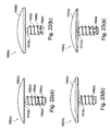
- FIGS. 22 and 23 illustrate various views of a partial humeral head prosthesis according to a second embodiment of the present invention.
- the invention provides prosthetic assembly for prosthetic and surgical methods for reconstitution of a joint, with special applications to the shoulder joint.
- the prosthetic assembly includes a partial humeral head prosthesis component that is configured to be inserted in a socket formed in the humerus.
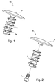
- FIGS. 1-5 illustrate a first exemplary embodiment of a partial humeral head prosthesis 10 of the present invention.
- Partial humeral head prosthesis 10 comprises a partial humeral head prosthesis cap 4 securely engaged to a partial implant or screw 2 by shoulder post 1.
- FIGS. 3(a)-(e) illustrate additional views of the partial humeral head prosthesis implant or screw.2.
- FIGS.4(a)-(c) illustrate additional views of the partial humeral head prosthesis cap 4.
- FIGS. 5(a)-(b) illustrate additional views of the shoulder post or pin 1.
- prosthesis cap 4 of the partial humeral head prosthesis 10 is configured to allow replacement of a portion of the humeral head with the prosthesis cap.
- partial humeral head prosthesis cap 4 has a convex configuration (a partial eclipse-type configuration), which is similar to the curvature of the humeral head to allow the prosthesis cap 4 to reconstruct the anatomy of the damaged humeral head.
- convex outer surface 4a ( FIGS. 4(a)-4(c) ) of the prosthesis cap 4 will permit both the full anatomical reconstruction of the humeral head and the introduction of the convex surface within the glenoid cavity.
- the concave, inner surface 4b ( FIG. 4(a) ) abuts the surface of the damaged articular bone to be replaced (i.e., portion of the humerus) and permits containment of any fractured, damaged humeral head.
- the dimension and measurements of the partial humeral head prosthesis cap 4 are a function of the patient's anatomy.
- the partial humeral head prosthesis implant or screw 2 shown in FIGS.3(a)-(e) is engaged to the prosthesis cap 4 through shoulder post or pin 1 shown in FIGS. 5(a)-(b) .
- implant or screw 2 is provided with threads 2a to allow the insertion and subsequent fixation of the screw (with prosthesis cap 4 attached thereto) into the humerus diaphyseal channel.
- a plurality of fenestrations or holes 2b formed through the body of the screw 2 permit the passage of any fixing material (such as acrylic cement, for example) through the walls of the screw 2, to increase the fixation of the device within the diaphyseal channel.
- Partial humeral head prosthesis 10 may be manufactured from titanium alloy or other metallic materials.
- the partial humeral head prosthesis cap 4 preferably is manufactured from materials similar to those of the screw 2 and pin 1.
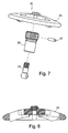
- FIGS. 6-8 illustrate various views of partial humeral head prosthesis duster 20 of the present invention.
- the partial humeral head prosthesis duster 20 comprises duster cap 25 securely engaging reamer 23 through ball post 21 and pin 22.
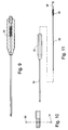
- FIGS. 9-11 illustrate a driver 30 for the partial humeral head prosthesis 10 of the present invention.
- Driver 30 comprises an inner rod 33 disposed within a cannulated rod 34, and a handle 32.
- Driver 30 also comprises a spring driver 36, a spring plug 35 and ball bearings 31.
- FIG. 12 illustrates a drill guide 40 for the partial humeral head prosthesis 10 of the present invention.
- Drill guide 40 comprises a handle frame 44, a guide arm 43, pins 41, 42 and spring latch 45.
- FIG. 13 shows a drill sleeve 50 for use with the drill guide 40 of FIG. 12 in connection with the present invention.
- FIG. 14 illustrates a threaded pin 60 for attachment to, and retrograde drilling of, duster 20 in connection with the present invention, as described in the technique below.
- the present invention also provides a method of conducting arthroscopic surgery by fixating the humeral head prosthesis 10 of the present invention within a socket in the humerus.
- Preparation for an exemplary surgical technique relies upon radiographic film, surgical templates, and trial implants to determine and select the appropriate combination of end cap 4, screw 2 and pin 1 that make up partial humeral head prosthesis (implant) 10 to meet the patient's anatomical requirements.
- the remaining fractured/damaged humerus is resected using appropriate instrumentation designed specifically for the implant system.
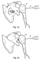
- FIGS. 15-21 depict a method of replacing a portion of the humeral head with the partial humeral head prosthesis 10 of the present invention
- FIGS. 22 and 23 illustrate front and perspective views, respectively, of additional embodiments of a partial humeral head prosthesis 100(a), 100(b) formed according to a second embodiment of the present invention.
- Partial humeral head prosthesis 100(a), 100(b) is similar to the partial humeral head prosthesis 10 described above, but differs in that humeral head prosthesis 100(a), 100(b) is formed as a unitary structure rather than as an assembled structure (i.e., a partial humeral head prosthesis cap is integral to a partial implant or screw, and not assembled to it).
- Partial humeral head prosthesis 100(a), 100(b) comprises a partial humeral head prosthesis cap 104(a), 104(b) securely attached to, and integral with, a partial implant or screw 102(a), 102(b).
- prosthesis cap 104(a), 104(b) is configured to allow replacement of a portion of the humeral head with the prosthesis cap.
- partial humeral head prosthesis cap 104(a), 104(b) has a convex configuration (a partial eclipse-type configuration), which is similar to the curvature of the humeral head to allow the prosthesis cap to reconstruct the anatomy of the damaged humeral head.
- the convex outer surface of the prosthesis cap 104(a), 104(b) permits both the full anatomical reconstruction of the humeral head and the introduction of the convex surface within the glenoid cavity.
- the concave, inner surface abuts the surface of the damaged articular bone to be replaced (i.e., portion of the humerus) and permits containment of any fractured, damaged humeral head.
- the dimension and measurements of the partial humeral head prosthesis cap 104(a), 104(b) are a function of the patient's anatomy.
- Engagement element (neck portion) 101(a), 101(b) is provided between the partial humeral head prosthesis implant or screw 102(a), 102(b) and the prosthesis cap 104(a), 104(b).
- Implant or screw 102(a), 102(b) is provided with threads 108(a), 108(b) to allow the insertion and subsequent fixation of the screw (with prosthesis cap attached thereto) into the humerus diaphyseal channel.
- the length of the implant 102(a), 102(b) varies according to the length of the diaphyseal channel of the humerus.
- a plurality of fenestrations or holes 106(a), 106(b) are formed through the body of the screw 102(a), 102(b) to permit the passage of any fixing material (such as acrylic cement, for example) through the walls of the screw, to increase the fixation of the device within the diaphyseal channel.
- the number of the fenestrations or holes 106(a), 106(b) depends on the length of the implant 102(a), 102(b) and also on the length of the diaphyseal channel of the humerus.
- Partial humeral head prosthesis 100(a), 100(b) may be manufactured from titanium alloy or other metallic materials.
- the partial humeral head prosthesis cap 104(a), 104(b) preferably is manufactured from materials similar to those of the screw 102(a), 102(b).
- Methods of conducting arthroscopic surgery by fixating the humeral head prosthesis 100(a), 100(b) within a socket in the humerus may be conducted by steps similar to those described and illustrated above with reference to humeral head prosthesis 10 of the first embodiment (for the humeral repair illustrated in FIGS. 15-21 ). Selection of the appropriate size for the partial humeral head prosthesis (implant) 100(a), 100(b) is based on the patient's anatomical requirements. The specific steps proceed as detailed above and with reference to FIGS. 15-21 .
Landscapes
- Health & Medical Sciences (AREA)
- Life Sciences & Earth Sciences (AREA)
- Surgery (AREA)
- Veterinary Medicine (AREA)
- Animal Behavior & Ethology (AREA)
- Orthopedic Medicine & Surgery (AREA)
- Oral & Maxillofacial Surgery (AREA)
- Engineering & Computer Science (AREA)
- Biomedical Technology (AREA)
- Heart & Thoracic Surgery (AREA)
- Public Health (AREA)
- General Health & Medical Sciences (AREA)
- Nuclear Medicine, Radiotherapy & Molecular Imaging (AREA)
- Molecular Biology (AREA)
- Medical Informatics (AREA)
- Dentistry (AREA)
- Cardiology (AREA)
- Transplantation (AREA)
- Vascular Medicine (AREA)
- Prostheses (AREA)
Abstract
Description
- The present invention relates to surgical reconstitution of anatomical structures and, in particular, to prosthetic replacement of such structures.
- Instability and other maladies of human joints, such as arthrosis or fracture, can be sufficiently acute that prosthetic replacement of compromised joint features may be indicated. For example, in shoulder reconstruction, the humeral head may be replaced by first resecting the humeral head from the humerus and then installing a humeral prosthetic at the resection.
- Various prostheses have been designed to mimic the portion of the joint or joint region being replaced. A shoulder prostheses, for example, includes a stem to be anchored in the humeral canal and a hemispherical head to be positioned within the glenoid cavity of the scapula. The more-recently devised modular shoulder prostheses generally are modular systems that allow flexibility with respect to either the tilt angle or the radial offset between the head and stem.
- The present invention provides a novel prosthetic assembly for prosthetic and surgical methods for reconstitution of a joint, with special applications to the shoulder joint. The prosthetic assembly includes a partial humeral head component.
- The present invention also provides a method of conducting surgery by providing a prosthetic assembly comprising a partial humeral head component fixed within a socket formed in the humerus.
- These and other features and advantages of the invention will be more apparent from the following detailed description that is provided in connection with the accompanying drawings and illustrated exemplary embodiments of the invention.
-
FIGS. 1-5 illustrate various views of a partial humeral head prosthesis according to a first embodiment of the present invention; -
FIGS. 6-8 illustrate various views of a partial humeral head prosthesis duster of the present invention; -
FIGS. 9-11 illustrate various views of a driver for the partial humeral head prosthesis of the present invention; -
FIG. 12 illustrates a drill guide for installing the partial humeral head prosthesis of the present invention; -
FIG. 13 illustrates a drill sleeve for use with the drill guide of the present invention; -
FIG. 14 illustrates various views of a pin for retrograde drilling of the duster ofFIGS. 6-8 in connection with the present invention; -
FIGS. 15-21 illustrate steps of a method of replacing a portion of the humeral head with the partial humeral head prosthesis of the present invention; and -
FIGS. 22 and 23 illustrate various views of a partial humeral head prosthesis according to a second embodiment of the present invention. - The invention provides prosthetic assembly for prosthetic and surgical methods for reconstitution of a joint, with special applications to the shoulder joint. As detailed below, the prosthetic assembly includes a partial humeral head prosthesis component that is configured to be inserted in a socket formed in the humerus.
- Referring now to the drawings, where like elements are designated by like reference numerals,
FIGS. 1-5 illustrate a first exemplary embodiment of a partialhumeral head prosthesis 10 of the present invention. Partialhumeral head prosthesis 10 comprises a partial humeralhead prosthesis cap 4 securely engaged to a partial implant orscrew 2 by shoulder post 1.FIGS. 3(a)-(e) illustrate additional views of the partial humeral head prosthesis implant or screw.2.FIGS.4(a)-(c) illustrate additional views of the partial humeralhead prosthesis cap 4.FIGS. 5(a)-(b) illustrate additional views of the shoulder post or pin 1. - As shown in the drawings,
prosthesis cap 4 of the partialhumeral head prosthesis 10 is configured to allow replacement of a portion of the humeral head with the prosthesis cap. In an exemplary embodiment, and as shown inFIGS.4(a)-(c) , partial humeralhead prosthesis cap 4 has a convex configuration (a partial eclipse-type configuration), which is similar to the curvature of the humeral head to allow theprosthesis cap 4 to reconstruct the anatomy of the damaged humeral head. As described below, convexouter surface 4a (FIGS. 4(a)-4(c) ) of theprosthesis cap 4 will permit both the full anatomical reconstruction of the humeral head and the introduction of the convex surface within the glenoid cavity. The concave,inner surface 4b (FIG. 4(a) ) abuts the surface of the damaged articular bone to be replaced (i.e., portion of the humerus) and permits containment of any fractured, damaged humeral head. The dimension and measurements of the partial humeralhead prosthesis cap 4 are a function of the patient's anatomy. - The partial humeral head prosthesis implant or
screw 2 shown inFIGS.3(a)-(e) is engaged to theprosthesis cap 4 through shoulder post or pin 1 shown inFIGS. 5(a)-(b) . As detailed inFIGS. 3(a)-(e) , implant orscrew 2 is provided withthreads 2a to allow the insertion and subsequent fixation of the screw (withprosthesis cap 4 attached thereto) into the humerus diaphyseal channel. A plurality of fenestrations orholes 2b formed through the body of thescrew 2 permit the passage of any fixing material (such as acrylic cement, for example) through the walls of thescrew 2, to increase the fixation of the device within the diaphyseal channel. - Partial
humeral head prosthesis 10 may be manufactured from titanium alloy or other metallic materials. The partial humeralhead prosthesis cap 4 preferably is manufactured from materials similar to those of thescrew 2 and pin 1. -
FIGS. 6-8 illustrate various views of partial humeralhead prosthesis duster 20 of the present invention. As shown in the drawings, the partial humeralhead prosthesis duster 20 comprisesduster cap 25 securely engagingreamer 23 throughball post 21 andpin 22. -
FIGS. 9-11 illustrate adriver 30 for the partialhumeral head prosthesis 10 of the present invention.Driver 30 comprises aninner rod 33 disposed within acannulated rod 34, and ahandle 32.Driver 30 also comprises aspring driver 36, aspring plug 35 andball bearings 31. -
FIG. 12 illustrates adrill guide 40 for the partialhumeral head prosthesis 10 of the present invention.Drill guide 40 comprises ahandle frame 44, aguide arm 43,pins spring latch 45. -
FIG. 13 shows adrill sleeve 50 for use with thedrill guide 40 ofFIG. 12 in connection with the present invention.FIG. 14 illustrates a threadedpin 60 for attachment to, and retrograde drilling of,duster 20 in connection with the present invention, as described in the technique below. - The present invention also provides a method of conducting arthroscopic surgery by fixating the
humeral head prosthesis 10 of the present invention within a socket in the humerus. Preparation for an exemplary surgical technique relies upon radiographic film, surgical templates, and trial implants to determine and select the appropriate combination ofend cap 4,screw 2 and pin 1 that make up partial humeral head prosthesis (implant) 10 to meet the patient's anatomical requirements. The remaining fractured/damaged humerus is resected using appropriate instrumentation designed specifically for the implant system. - Specific steps of an exemplary method of humeral repair according to the present invention are detailed below and with reference to
FIGS. 15-21 (which depict a method of replacing a portion of the humeral head with the partialhumeral head prosthesis 10 of the present invention): - Use
drill guide 40 with orthogonal orientation features to place 2.4 mm drill pin thruhumeral head 88, exiting at center of focal defect (FIG. 15 ). - Remove
drill guide 40, leaving the 2.4 mm drill pin in place. - Over-drill with 4 mm cannulated drill over 2.4 mm drill pin to form tunnel or hole 80 (
FIG. 16 ) through thehumerus 88, remove 4 mm drill leaving 2.4 mm drill pin in place. - Place
sleeve component 50 over 2.4 mm drill pin, verifying whethersleeve 50 is in view with arthroscope. Remove 2.4 mm drill pin. - Insert threaded
pin component 60 upsleeve 50 into view of arthroscope. Bring duster component 20 (FIG. 17 ), loaded onto insertion hand instrument, through rotator cuff interval portal into view. Assembleduster 20 to threadedpin 60 by hand. - Load power drill onto threaded
pin 60 and apply retrograde force while running drill to create a counterbore socket at focal defect location (FIG. 18 ). - Remove power drill. Grasp
duster component 20 with insertion hand instrument and remove threadedpin 60, then removeduster component 20.Sleeve 50 should still be in place. - Insert
implant inserter component 10 up sleeve into view of arthroscope. Bringimplant 10, loaded onto insertion hand instrument, thru the rotator cuff interval portal into view (FIG. 19 ). Assembleimplant 10 on inserter by hand. -
Retrograde insert implant 10 into the prepared socket untilcap 4 ofimplant 10 is flush with the surrounding articular surface of the humerus (FIG. 20 ). - Remove the inserter, remove
sleeve 50 and confirm thatimplant 10 is correctly installed (FIG. 21 ). -
FIGS. 22 and 23 illustrate front and perspective views, respectively, of additional embodiments of a partial humeral head prosthesis 100(a), 100(b) formed according to a second embodiment of the present invention. Partial humeral head prosthesis 100(a), 100(b) is similar to the partialhumeral head prosthesis 10 described above, but differs in that humeral head prosthesis 100(a), 100(b) is formed as a unitary structure rather than as an assembled structure (i.e., a partial humeral head prosthesis cap is integral to a partial implant or screw, and not assembled to it). Partial humeral head prosthesis 100(a), 100(b) comprises a partial humeral head prosthesis cap 104(a), 104(b) securely attached to, and integral with, a partial implant or screw 102(a), 102(b). - As shown in
FIGS. 22 and 23 , prosthesis cap 104(a), 104(b) is configured to allow replacement of a portion of the humeral head with the prosthesis cap. As in the previously-described embodiment, partial humeral head prosthesis cap 104(a), 104(b) has a convex configuration (a partial eclipse-type configuration), which is similar to the curvature of the humeral head to allow the prosthesis cap to reconstruct the anatomy of the damaged humeral head. The convex outer surface of the prosthesis cap 104(a), 104(b) permits both the full anatomical reconstruction of the humeral head and the introduction of the convex surface within the glenoid cavity. The concave, inner surface abuts the surface of the damaged articular bone to be replaced (i.e., portion of the humerus) and permits containment of any fractured, damaged humeral head. The dimension and measurements of the partial humeral head prosthesis cap 104(a), 104(b) are a function of the patient's anatomy. - Engagement element (neck portion) 101(a), 101(b) is provided between the partial humeral head prosthesis implant or screw 102(a), 102(b) and the prosthesis cap 104(a), 104(b). Implant or screw 102(a), 102(b) is provided with threads 108(a), 108(b) to allow the insertion and subsequent fixation of the screw (with prosthesis cap attached thereto) into the humerus diaphyseal channel. As shown in
FIGS. 22 and 23 , the length of the implant 102(a), 102(b) varies according to the length of the diaphyseal channel of the humerus. - A plurality of fenestrations or holes 106(a), 106(b) are formed through the body of the screw 102(a), 102(b) to permit the passage of any fixing material (such as acrylic cement, for example) through the walls of the screw, to increase the fixation of the device within the diaphyseal channel. The number of the fenestrations or holes 106(a), 106(b) depends on the length of the implant 102(a), 102(b) and also on the length of the diaphyseal channel of the humerus.
- Partial humeral head prosthesis 100(a), 100(b) may be manufactured from titanium alloy or other metallic materials. The partial humeral head prosthesis cap 104(a), 104(b) preferably is manufactured from materials similar to those of the screw 102(a), 102(b).
- Methods of conducting arthroscopic surgery by fixating the humeral head prosthesis 100(a), 100(b) within a socket in the humerus may be conducted by steps similar to those described and illustrated above with reference to humeral head prosthesis 10 of the first embodiment (for the humeral repair illustrated in
FIGS. 15-21 ). Selection of the appropriate size for the partial humeral head prosthesis (implant) 100(a), 100(b) is based on the patient's anatomical requirements. The specific steps proceed as detailed above and with reference toFIGS. 15-21 . - The above description and drawings illustrate preferred embodiments which achieve the objects, features and advantages of the present invention. It is not intended that the present invention be limited to the illustrated embodiments. Any modification of the present invention which comes within the spirit and scope of the following claims should be considered part of the present invention.
Claims (8)
- A prosthetic for replacing a portion of a bone, comprising:a spherical head having a convex surface suitable to be introduced within a joint cavity and a concave surface that contacts the bone a stem extending perpendicularly from the spherical head; anda post, attached to the stem, for insertion into the bone.
- The prosthetic of claim 1, wherein the spherical head is contoured to engage a complementary articular surface.
- The prosthetic of claim 1, wherein the joint cavity is the humerus glenoid cavity.
- The prosthetic of claim 1, wherein the post is a cannulated member insertable within a diaphyseal channel of the bone.
- The prosthetic of claim 4, wherein the cannulated member is a threaded screw.
- The prosthetic of claim 4, wherein the cannulated member is provided with a plurality of fenestrations.
- The prosthetic of claim 1, wherein the post, the spherical head, and the stem are removably attached to each other.
- The prosthetic of claim 1, wherein the post, the spherical head, and the stem are provided as a unitary, integral structure.
Applications Claiming Priority (1)
| Application Number | Priority Date | Filing Date | Title |
|---|---|---|---|
| US91528007P | 2007-05-01 | 2007-05-01 |
Publications (3)
| Publication Number | Publication Date |
|---|---|
| EP1990026A2 true EP1990026A2 (en) | 2008-11-12 |
| EP1990026A3 EP1990026A3 (en) | 2008-11-19 |
| EP1990026B1 EP1990026B1 (en) | 2014-03-12 |
Family
ID=39769226
Family Applications (1)
| Application Number | Title | Priority Date | Filing Date |
|---|---|---|---|
| EP08251602.2A Active EP1990026B1 (en) | 2007-05-01 | 2008-05-01 | Prosthetic for replacing a portion of a bone |
Country Status (2)
| Country | Link |
|---|---|
| US (1) | US8591592B2 (en) |
| EP (1) | EP1990026B1 (en) |
Cited By (2)
| Publication number | Priority date | Publication date | Assignee | Title |
|---|---|---|---|---|
| CN102188298A (en) * | 2011-07-13 | 2011-09-21 | 张前法 | Biotype femoral head surface substitutive prosthesis |
| IT201600080874A1 (en) * | 2016-08-01 | 2018-02-01 | Alfonso Sciarrabone | SHOULDER PROSTHETIC IMPLANTATION |
Families Citing this family (82)
| Publication number | Priority date | Publication date | Assignee | Title |
|---|---|---|---|---|
| US8177841B2 (en) | 2000-05-01 | 2012-05-15 | Arthrosurface Inc. | System and method for joint resurface repair |
| US6610067B2 (en) | 2000-05-01 | 2003-08-26 | Arthrosurface, Incorporated | System and method for joint resurface repair |
| EP2314257B9 (en) | 2000-05-01 | 2013-02-27 | ArthroSurface, Inc. | System for joint resurface repair |
| US7914545B2 (en) | 2002-12-03 | 2011-03-29 | Arthrosurface, Inc | System and method for retrograde procedure |
| US8388624B2 (en) | 2003-02-24 | 2013-03-05 | Arthrosurface Incorporated | Trochlear resurfacing system and method |
| WO2005051231A2 (en) | 2003-11-20 | 2005-06-09 | Arthrosurface, Inc. | Retrograde delivery of resurfacing devices |
| JP2008504107A (en) | 2004-06-28 | 2008-02-14 | アースロサーフィス・インコーポレーテッド | Joint surface replacement system |
| US7828853B2 (en) | 2004-11-22 | 2010-11-09 | Arthrosurface, Inc. | Articular surface implant and delivery system |
| US8172855B2 (en) | 2004-11-24 | 2012-05-08 | Abdou M S | Devices and methods for inter-vertebral orthopedic device placement |
| AU2007332787A1 (en) | 2006-12-11 | 2008-06-19 | Arthrosurface Incorporated | Retrograde resection apparatus and method |
| US20090287309A1 (en) | 2007-01-30 | 2009-11-19 | Tornier Sas | Intra-articular joint replacement |
| WO2009111481A1 (en) | 2008-03-03 | 2009-09-11 | Arthrosurface Incorporated | Bone resurfacing system and method |
| US20100087923A1 (en) * | 2008-08-23 | 2010-04-08 | Abdou M Samy | Implants for facet joint repair and methods use |
| US20100145451A1 (en) | 2008-12-04 | 2010-06-10 | Derek Dee | Joint support and subchondral support system |
| US10610364B2 (en) | 2008-12-04 | 2020-04-07 | Subchondral Solutions, Inc. | Method for ameliorating joint conditions and diseases and preventing bone hypertrophy |
| CA3064646C (en) | 2009-04-17 | 2023-01-03 | Arthrosurface Incorporated | Glenoid resurfacing system and method |
| WO2010121250A1 (en) | 2009-04-17 | 2010-10-21 | Arthrosurface Incorporated | Glenoid resurfacing system and method |
| US10945743B2 (en) | 2009-04-17 | 2021-03-16 | Arthrosurface Incorporated | Glenoid repair system and methods of use thereof |
| US8764806B2 (en) | 2009-12-07 | 2014-07-01 | Samy Abdou | Devices and methods for minimally invasive spinal stabilization and instrumentation |
| FR2955247B1 (en) | 2010-01-21 | 2013-04-26 | Tornier Sa | GLENOIDAL COMPONENT OF SHOULDER PROSTHESIS |
| US8968411B2 (en) * | 2009-12-17 | 2015-03-03 | Zimmer, Inc. | Modular elbow prosthesis |
| EP2712564B1 (en) * | 2010-02-26 | 2017-04-05 | Biedermann Technologies GmbH & Co. KG | Bone screw |
| BR112012022482A2 (en) | 2010-03-05 | 2016-07-19 | Arthrosurface Inc | tibial surface recomposition system and method. |
| USD685474S1 (en) | 2010-07-06 | 2013-07-02 | Tornier, Inc. | Prosthesis anchor |
| FR2971144A1 (en) | 2011-02-08 | 2012-08-10 | Tornier Sa | GLENOIDAL IMPLANT FOR SHOULDER PROSTHESIS AND SURGICAL KIT |
| EP2484315B1 (en) * | 2011-02-07 | 2014-06-11 | Arthrex, Inc. | Minimally invasive total hip replacement |
| US9066716B2 (en) | 2011-03-30 | 2015-06-30 | Arthrosurface Incorporated | Suture coil and suture sheath for tissue repair |
| US9364333B1 (en) * | 2011-04-01 | 2016-06-14 | The Lonnie and Shannon Paulos Trust | Transosseous methods and systems for joint repair |
| FR2978912A1 (en) | 2011-08-10 | 2013-02-15 | Tornier Inc | ANCILLARY EXTRACTION OF A PROSTHESIS |
| US8845728B1 (en) | 2011-09-23 | 2014-09-30 | Samy Abdou | Spinal fixation devices and methods of use |
| EP2804565B1 (en) | 2011-12-22 | 2018-03-07 | Arthrosurface Incorporated | System for bone fixation |
| US9078673B2 (en) * | 2012-01-18 | 2015-07-14 | Ortho Innovations, Inc. | Method of humeral head resurfacing and/or replacement and system for accomplishing the method |
| US20130226240A1 (en) | 2012-02-22 | 2013-08-29 | Samy Abdou | Spinous process fixation devices and methods of use |
| US10201374B2 (en) | 2012-06-22 | 2019-02-12 | Zimmer, Inc. | Assembly tool for a prosthesis |
| US8936647B2 (en) | 2012-06-22 | 2015-01-20 | Zimmer, Inc. | Elbow prosthesis |
| DE112013003358T5 (en) | 2012-07-03 | 2015-03-19 | Arthrosurface, Inc. | System and procedure for joint surface replacement and repair |
| US9198767B2 (en) | 2012-08-28 | 2015-12-01 | Samy Abdou | Devices and methods for spinal stabilization and instrumentation |
| US9610084B2 (en) | 2012-09-12 | 2017-04-04 | Peter Michael Sutherland Walker | Method and apparatus for hip replacements |
| US9320617B2 (en) | 2012-10-22 | 2016-04-26 | Cogent Spine, LLC | Devices and methods for spinal stabilization and instrumentation |
| US10973646B2 (en) | 2013-03-11 | 2021-04-13 | Catalyst Orthoscience Inc. | Stabilized drill guide |
| US20170319348A1 (en) | 2015-08-10 | 2017-11-09 | Catalyst Orthoscience Inc. | Arthroplasty prostheses with multi-axis fixation |
| US9814588B2 (en) | 2015-08-10 | 2017-11-14 | Catalyst Orthoscience Inc. | Glenoid arthroplasty with multi-directional fixation |
| US11007063B2 (en) | 2013-03-11 | 2021-05-18 | Catalyst Orthoscience Inc. | Offset reamers |
| US9814471B2 (en) | 2013-03-11 | 2017-11-14 | Catalyst Orthoscience Inc. | Glenoid arthroplasty and offset reamers |
| US9775716B2 (en) | 2013-03-11 | 2017-10-03 | Catalyst Orthoscience Inc. | Glenoid arthroplasty |
| US9492200B2 (en) | 2013-04-16 | 2016-11-15 | Arthrosurface Incorporated | Suture system and method |
| EP3777777B1 (en) | 2014-01-03 | 2023-04-05 | Howmedica Osteonics Corp. | Glenoid implant for a shoulder prosthesis |
| US10456264B2 (en) | 2014-01-24 | 2019-10-29 | Tornier, Inc. | Humeral implant anchor system |
| US12023253B2 (en) | 2014-01-24 | 2024-07-02 | Howmedica Osteonics Corp. | Humeral implant anchor system |
| US9931219B2 (en) | 2014-03-07 | 2018-04-03 | Arthrosurface Incorporated | Implant and anchor assembly |
| US10624748B2 (en) | 2014-03-07 | 2020-04-21 | Arthrosurface Incorporated | System and method for repairing articular surfaces |
| US11607319B2 (en) | 2014-03-07 | 2023-03-21 | Arthrosurface Incorporated | System and method for repairing articular surfaces |
| US9681960B2 (en) | 2014-05-16 | 2017-06-20 | Howmedica Osteonics Corp. | Guides for fracture system |
| US10575968B2 (en) | 2014-05-16 | 2020-03-03 | Howmedica Osteonics Corp. | Guides for fracture system |
| US10722374B2 (en) | 2015-05-05 | 2020-07-28 | Tornier, Inc. | Convertible glenoid implant |
| US10857003B1 (en) | 2015-10-14 | 2020-12-08 | Samy Abdou | Devices and methods for vertebral stabilization |
| CN108495595B (en) | 2015-11-25 | 2022-02-01 | 软骨解决方案股份有限公司 | Methods, systems, and devices for repairing anatomical joint conditions |
| US10463499B2 (en) | 2016-03-25 | 2019-11-05 | Tornier, Inc. | Stemless shoulder implant with fixation components |
| WO2018022227A1 (en) | 2016-07-28 | 2018-02-01 | Tornier, Inc. | Stemless prosthesis anchor component |
| US10744000B1 (en) | 2016-10-25 | 2020-08-18 | Samy Abdou | Devices and methods for vertebral bone realignment |
| US10973648B1 (en) | 2016-10-25 | 2021-04-13 | Samy Abdou | Devices and methods for vertebral bone realignment |
| CN110709034A (en) * | 2017-06-02 | 2020-01-17 | Ot医疗技术股份有限公司 | Radial head implant |
| CA3108761A1 (en) | 2017-08-04 | 2019-02-07 | Arthrosurface Incorporated | Multicomponent articular surface implant |
| WO2019060780A2 (en) | 2017-09-25 | 2019-03-28 | Tornier, Inc. | Patient specific stemless prosthesis anchor components |
| EP4497417B1 (en) | 2017-10-16 | 2026-04-29 | Stryker European Operations Limited | Shoulder implants |
| US11399948B2 (en) | 2017-12-11 | 2022-08-02 | Howmedica Osteonics Corp. | Stemless prosthesis anchor components and kits |
| IL275811B2 (en) | 2018-01-02 | 2025-05-01 | Cartiheal 2009 Ltd | Implantation protocol for optimized solid substrates for promoting cell and tissue growth |
| US10813769B2 (en) | 2018-07-24 | 2020-10-27 | DePuy Synthes Products, Inc. | Baseplate of a modular shoulder joint prosthesis and related methods for implanting the same |
| AU2019352591B2 (en) | 2018-10-02 | 2021-08-12 | Howmedica Osteonics Corp. | Shoulder prosthesis components and assemblies |
| US11179248B2 (en) | 2018-10-02 | 2021-11-23 | Samy Abdou | Devices and methods for spinal implantation |
| CN109730760A (en) * | 2019-01-24 | 2019-05-10 | 丁伟 | A device for osseous repair and reconstruction of shoulder joint |
| GB2609338B (en) | 2019-03-12 | 2023-06-14 | Arthrosurface Inc | Humeral and glenoid articular surface implant systems and methods |
| AU2020276186C1 (en) | 2019-05-13 | 2022-07-21 | Howmedica Osteonics Corp. | Glenoid baseplate and implant assemblies |
| NL1043315B1 (en) * | 2019-06-27 | 2021-02-01 | Jointsphere B V | Plug-shaped implant for the replacement and regeneration of biological tissue and method for preparing the implant |
| US20220265290A1 (en) | 2019-08-09 | 2022-08-25 | Howmedica Osteonics Corp. | Apparatuses and methods for implanting glenoid prostheses |
| CN114502106A (en) | 2019-10-01 | 2022-05-13 | 赫迈迪卡奥斯特尼克斯公司 | Shoulder prosthesis components and assemblies |
| USD951449S1 (en) | 2019-10-01 | 2022-05-10 | Howmedica Osteonics Corp. | Humeral implant |
| AU2021202801A1 (en) | 2020-05-07 | 2021-11-25 | Howmedica Osteonics Corp. | Stemless metaphyseal humeral implant |
| JP7620116B2 (en) | 2021-02-26 | 2025-01-22 | ハウメディカ オステオニクス コーポレイション | Glenoid implant components and instruments thereof |
| RU210322U1 (en) * | 2021-09-05 | 2022-04-07 | Андрей Юрьевич Худошин | Shaftless endoprosthesis of the shoulder joint |
| WO2025151535A1 (en) * | 2024-01-08 | 2025-07-17 | Hyalex Orthopaedics, Inc. | Metatarsophalangeal joint implants and methods thereof |
| CN119279868A (en) * | 2024-06-26 | 2025-01-10 | 北京市春立正达医疗器械股份有限公司 | An implant prosthesis for partial surface shoulder replacement |
Citations (5)
| Publication number | Priority date | Publication date | Assignee | Title |
|---|---|---|---|---|
| FR2578739A1 (en) | 1985-03-12 | 1986-09-19 | Rambert Andre | Humeral prosthesis |
| WO1997047257A1 (en) | 1996-06-14 | 1997-12-18 | Mosseri Raphael | Total hip prosthesis for endo-articular implantation, and ancillary device therefor |
| US20020022889A1 (en) | 1995-08-23 | 2002-02-21 | Jean Chibrac | Joint prosthesis members and method for making same |
| EP1260200A1 (en) | 2001-05-18 | 2002-11-27 | Copf, Peter, Dr. med | Cementless hip joint endoprosthesis for replacing the surface of the proximal femur |
| EP1407728A1 (en) | 2002-10-07 | 2004-04-14 | Centerpulse Orthopedics Ltd. | Femoral head prosthesis |
Family Cites Families (7)
| Publication number | Priority date | Publication date | Assignee | Title |
|---|---|---|---|---|
| CH648197A5 (en) * | 1980-05-28 | 1985-03-15 | Synthes Ag | IMPLANT AND SCREW FASTENING ON ITS BONE. |
| US5100405A (en) * | 1990-09-07 | 1992-03-31 | Mclaren Alexander C | Locking cap for medical implants |
| US5409332A (en) * | 1991-10-02 | 1995-04-25 | Chabot, Jr.; Bertin R. | Universal joint |
| US7901408B2 (en) * | 2002-12-03 | 2011-03-08 | Arthrosurface, Inc. | System and method for retrograde procedure |
| WO2005016123A2 (en) * | 2003-08-11 | 2005-02-24 | Chudik Steven C M D | Devices and methods used for shoulder replacement |
| WO2005051231A2 (en) * | 2003-11-20 | 2005-06-09 | Arthrosurface, Inc. | Retrograde delivery of resurfacing devices |
| US7503921B2 (en) * | 2004-01-13 | 2009-03-17 | Symmetry Medical, Inc. | Variable angle orthopaedic reamer driver |
-
2008
- 2008-05-01 US US12/113,849 patent/US8591592B2/en active Active
- 2008-05-01 EP EP08251602.2A patent/EP1990026B1/en active Active
Patent Citations (5)
| Publication number | Priority date | Publication date | Assignee | Title |
|---|---|---|---|---|
| FR2578739A1 (en) | 1985-03-12 | 1986-09-19 | Rambert Andre | Humeral prosthesis |
| US20020022889A1 (en) | 1995-08-23 | 2002-02-21 | Jean Chibrac | Joint prosthesis members and method for making same |
| WO1997047257A1 (en) | 1996-06-14 | 1997-12-18 | Mosseri Raphael | Total hip prosthesis for endo-articular implantation, and ancillary device therefor |
| EP1260200A1 (en) | 2001-05-18 | 2002-11-27 | Copf, Peter, Dr. med | Cementless hip joint endoprosthesis for replacing the surface of the proximal femur |
| EP1407728A1 (en) | 2002-10-07 | 2004-04-14 | Centerpulse Orthopedics Ltd. | Femoral head prosthesis |
Cited By (2)
| Publication number | Priority date | Publication date | Assignee | Title |
|---|---|---|---|---|
| CN102188298A (en) * | 2011-07-13 | 2011-09-21 | 张前法 | Biotype femoral head surface substitutive prosthesis |
| IT201600080874A1 (en) * | 2016-08-01 | 2018-02-01 | Alfonso Sciarrabone | SHOULDER PROSTHETIC IMPLANTATION |
Also Published As
| Publication number | Publication date |
|---|---|
| US20080306601A1 (en) | 2008-12-11 |
| EP1990026A3 (en) | 2008-11-19 |
| US8591592B2 (en) | 2013-11-26 |
| EP1990026B1 (en) | 2014-03-12 |
Similar Documents
| Publication | Publication Date | Title |
|---|---|---|
| EP1990026B1 (en) | Prosthetic for replacing a portion of a bone | |
| EP2353549B1 (en) | Articulating humeral head prosthesis | |
| US9295556B2 (en) | Minimally invasive total hip replacement | |
| US20240415673A1 (en) | Shoulder patient specific instrument | |
| US8632603B2 (en) | Implant positioning systems for orienting prosthesis | |
| CN103442665B (en) | implant | |
| CN103533912B (en) | Arthroplasty plate | |
| EP2792334B1 (en) | Orthopaedic implant | |
| US6783549B1 (en) | Modular humeral head resurfacing system | |
| US8317845B2 (en) | Screw and method of use | |
| US7691150B2 (en) | Modular plate and keel provisionals | |
| EP1986575B1 (en) | A glenoid component of a shoulder joint prosthesis | |
| US20040059424A1 (en) | Metal back prosthetic glenoid component with cemented pegs and hollow metal cage screw | |
| US10426624B2 (en) | Glenosphere guide tool | |
| US11298245B2 (en) | Method for surgical application of a glenoid prosthesis component of a shoulder joint prosthesis and relating surgical instruments | |
| US20160113645A1 (en) | Implant with suture anchor fixation capability | |
| AU2022227496A9 (en) | Glenoid implant components and instruments therefor |
Legal Events
| Date | Code | Title | Description |
|---|---|---|---|
| PUAI | Public reference made under article 153(3) epc to a published international application that has entered the european phase |
Free format text: ORIGINAL CODE: 0009012 |
|
| PUAL | Search report despatched |
Free format text: ORIGINAL CODE: 0009013 |
|
| AK | Designated contracting states |
Kind code of ref document: A2 Designated state(s): AT BE BG CH CY CZ DE DK EE ES FI FR GB GR HR HU IE IS IT LI LT LU LV MC MT NL NO PL PT RO SE SI SK TR |
|
| AX | Request for extension of the european patent |
Extension state: AL BA MK RS |
|
| AK | Designated contracting states |
Kind code of ref document: A3 Designated state(s): AT BE BG CH CY CZ DE DK EE ES FI FR GB GR HR HU IE IS IT LI LT LU LV MC MT NL NO PL PT RO SE SI SK TR |
|
| AX | Request for extension of the european patent |
Extension state: AL BA MK RS |
|
| 17P | Request for examination filed |
Effective date: 20090519 |
|
| AKX | Designation fees paid |
Designated state(s): AT BE BG CH CY CZ DE DK EE ES FI FR GB GR HR HU IE IS IT LI LT LU LV MC MT NL NO PL PT RO SE SI SK TR |
|
| 17Q | First examination report despatched |
Effective date: 20120120 |
|
| GRAP | Despatch of communication of intention to grant a patent |
Free format text: ORIGINAL CODE: EPIDOSNIGR1 |
|
| INTG | Intention to grant announced |
Effective date: 20130924 |
|
| GRAS | Grant fee paid |
Free format text: ORIGINAL CODE: EPIDOSNIGR3 |
|
| GRAA | (expected) grant |
Free format text: ORIGINAL CODE: 0009210 |
|
| AK | Designated contracting states |
Kind code of ref document: B1 Designated state(s): AT BE BG CH CY CZ DE DK EE ES FI FR GB GR HR HU IE IS IT LI LT LU LV MC MT NL NO PL PT RO SE SI SK TR |
|
| REG | Reference to a national code |
Ref country code: GB Ref legal event code: FG4D |
|
| REG | Reference to a national code |
Ref country code: CH Ref legal event code: EP |
|
| REG | Reference to a national code |
Ref country code: AT Ref legal event code: REF Ref document number: 655725 Country of ref document: AT Kind code of ref document: T Effective date: 20140315 |
|
| REG | Reference to a national code |
Ref country code: IE Ref legal event code: FG4D |
|
| REG | Reference to a national code |
Ref country code: DE Ref legal event code: R096 Ref document number: 602008030768 Country of ref document: DE Effective date: 20140424 |
|
| REG | Reference to a national code |
Ref country code: NL Ref legal event code: VDEP Effective date: 20140312 |
|
| PG25 | Lapsed in a contracting state [announced via postgrant information from national office to epo] |
Ref country code: NO Free format text: LAPSE BECAUSE OF FAILURE TO SUBMIT A TRANSLATION OF THE DESCRIPTION OR TO PAY THE FEE WITHIN THE PRESCRIBED TIME-LIMIT Effective date: 20140612 Ref country code: LT Free format text: LAPSE BECAUSE OF FAILURE TO SUBMIT A TRANSLATION OF THE DESCRIPTION OR TO PAY THE FEE WITHIN THE PRESCRIBED TIME-LIMIT Effective date: 20140312 |
|
| REG | Reference to a national code |
Ref country code: LT Ref legal event code: MG4D |
|
| PG25 | Lapsed in a contracting state [announced via postgrant information from national office to epo] |
Ref country code: SE Free format text: LAPSE BECAUSE OF FAILURE TO SUBMIT A TRANSLATION OF THE DESCRIPTION OR TO PAY THE FEE WITHIN THE PRESCRIBED TIME-LIMIT Effective date: 20140312 Ref country code: CY Free format text: LAPSE BECAUSE OF FAILURE TO SUBMIT A TRANSLATION OF THE DESCRIPTION OR TO PAY THE FEE WITHIN THE PRESCRIBED TIME-LIMIT Effective date: 20140312 Ref country code: FI Free format text: LAPSE BECAUSE OF FAILURE TO SUBMIT A TRANSLATION OF THE DESCRIPTION OR TO PAY THE FEE WITHIN THE PRESCRIBED TIME-LIMIT Effective date: 20140312 |
|
| PG25 | Lapsed in a contracting state [announced via postgrant information from national office to epo] |
Ref country code: HR Free format text: LAPSE BECAUSE OF FAILURE TO SUBMIT A TRANSLATION OF THE DESCRIPTION OR TO PAY THE FEE WITHIN THE PRESCRIBED TIME-LIMIT Effective date: 20140312 Ref country code: LV Free format text: LAPSE BECAUSE OF FAILURE TO SUBMIT A TRANSLATION OF THE DESCRIPTION OR TO PAY THE FEE WITHIN THE PRESCRIBED TIME-LIMIT Effective date: 20140312 |
|
| PG25 | Lapsed in a contracting state [announced via postgrant information from national office to epo] |
Ref country code: EE Free format text: LAPSE BECAUSE OF FAILURE TO SUBMIT A TRANSLATION OF THE DESCRIPTION OR TO PAY THE FEE WITHIN THE PRESCRIBED TIME-LIMIT Effective date: 20140312 Ref country code: CZ Free format text: LAPSE BECAUSE OF FAILURE TO SUBMIT A TRANSLATION OF THE DESCRIPTION OR TO PAY THE FEE WITHIN THE PRESCRIBED TIME-LIMIT Effective date: 20140312 Ref country code: RO Free format text: LAPSE BECAUSE OF FAILURE TO SUBMIT A TRANSLATION OF THE DESCRIPTION OR TO PAY THE FEE WITHIN THE PRESCRIBED TIME-LIMIT Effective date: 20140312 Ref country code: IS Free format text: LAPSE BECAUSE OF FAILURE TO SUBMIT A TRANSLATION OF THE DESCRIPTION OR TO PAY THE FEE WITHIN THE PRESCRIBED TIME-LIMIT Effective date: 20140712 Ref country code: NL Free format text: LAPSE BECAUSE OF FAILURE TO SUBMIT A TRANSLATION OF THE DESCRIPTION OR TO PAY THE FEE WITHIN THE PRESCRIBED TIME-LIMIT Effective date: 20140312 Ref country code: BG Free format text: LAPSE BECAUSE OF FAILURE TO SUBMIT A TRANSLATION OF THE DESCRIPTION OR TO PAY THE FEE WITHIN THE PRESCRIBED TIME-LIMIT Effective date: 20140612 |
|
| PG25 | Lapsed in a contracting state [announced via postgrant information from national office to epo] |
Ref country code: ES Free format text: LAPSE BECAUSE OF FAILURE TO SUBMIT A TRANSLATION OF THE DESCRIPTION OR TO PAY THE FEE WITHIN THE PRESCRIBED TIME-LIMIT Effective date: 20140312 Ref country code: SK Free format text: LAPSE BECAUSE OF FAILURE TO SUBMIT A TRANSLATION OF THE DESCRIPTION OR TO PAY THE FEE WITHIN THE PRESCRIBED TIME-LIMIT Effective date: 20140312 Ref country code: PL Free format text: LAPSE BECAUSE OF FAILURE TO SUBMIT A TRANSLATION OF THE DESCRIPTION OR TO PAY THE FEE WITHIN THE PRESCRIBED TIME-LIMIT Effective date: 20140312 |
|
| REG | Reference to a national code |
Ref country code: DE Ref legal event code: R097 Ref document number: 602008030768 Country of ref document: DE |
|
| PG25 | Lapsed in a contracting state [announced via postgrant information from national office to epo] |
Ref country code: LU Free format text: LAPSE BECAUSE OF FAILURE TO SUBMIT A TRANSLATION OF THE DESCRIPTION OR TO PAY THE FEE WITHIN THE PRESCRIBED TIME-LIMIT Effective date: 20140501 Ref country code: PT Free format text: LAPSE BECAUSE OF FAILURE TO SUBMIT A TRANSLATION OF THE DESCRIPTION OR TO PAY THE FEE WITHIN THE PRESCRIBED TIME-LIMIT Effective date: 20140714 |
|
| REG | Reference to a national code |
Ref country code: CH Ref legal event code: PL |
|
| PLBE | No opposition filed within time limit |
Free format text: ORIGINAL CODE: 0009261 |
|
| STAA | Information on the status of an ep patent application or granted ep patent |
Free format text: STATUS: NO OPPOSITION FILED WITHIN TIME LIMIT |
|
| PG25 | Lapsed in a contracting state [announced via postgrant information from national office to epo] |
Ref country code: MC Free format text: LAPSE BECAUSE OF FAILURE TO SUBMIT A TRANSLATION OF THE DESCRIPTION OR TO PAY THE FEE WITHIN THE PRESCRIBED TIME-LIMIT Effective date: 20140312 Ref country code: DK Free format text: LAPSE BECAUSE OF FAILURE TO SUBMIT A TRANSLATION OF THE DESCRIPTION OR TO PAY THE FEE WITHIN THE PRESCRIBED TIME-LIMIT Effective date: 20140312 Ref country code: CH Free format text: LAPSE BECAUSE OF NON-PAYMENT OF DUE FEES Effective date: 20140531 Ref country code: LI Free format text: LAPSE BECAUSE OF NON-PAYMENT OF DUE FEES Effective date: 20140531 |
|
| 26N | No opposition filed |
Effective date: 20141215 |
|
| REG | Reference to a national code |
Ref country code: IE Ref legal event code: MM4A |
|
| REG | Reference to a national code |
Ref country code: DE Ref legal event code: R097 Ref document number: 602008030768 Country of ref document: DE Effective date: 20141215 |
|
| PG25 | Lapsed in a contracting state [announced via postgrant information from national office to epo] |
Ref country code: IE Free format text: LAPSE BECAUSE OF NON-PAYMENT OF DUE FEES Effective date: 20140501 |
|
| PG25 | Lapsed in a contracting state [announced via postgrant information from national office to epo] |
Ref country code: SI Free format text: LAPSE BECAUSE OF FAILURE TO SUBMIT A TRANSLATION OF THE DESCRIPTION OR TO PAY THE FEE WITHIN THE PRESCRIBED TIME-LIMIT Effective date: 20140312 |
|
| PG25 | Lapsed in a contracting state [announced via postgrant information from national office to epo] |
Ref country code: MT Free format text: LAPSE BECAUSE OF FAILURE TO SUBMIT A TRANSLATION OF THE DESCRIPTION OR TO PAY THE FEE WITHIN THE PRESCRIBED TIME-LIMIT Effective date: 20140312 |
|
| REG | Reference to a national code |
Ref country code: FR Ref legal event code: PLFP Year of fee payment: 9 |
|
| PG25 | Lapsed in a contracting state [announced via postgrant information from national office to epo] |
Ref country code: GR Free format text: LAPSE BECAUSE OF FAILURE TO SUBMIT A TRANSLATION OF THE DESCRIPTION OR TO PAY THE FEE WITHIN THE PRESCRIBED TIME-LIMIT Effective date: 20140613 |
|
| PG25 | Lapsed in a contracting state [announced via postgrant information from national office to epo] |
Ref country code: HU Free format text: LAPSE BECAUSE OF FAILURE TO SUBMIT A TRANSLATION OF THE DESCRIPTION OR TO PAY THE FEE WITHIN THE PRESCRIBED TIME-LIMIT; INVALID AB INITIO Effective date: 20080501 Ref country code: TR Free format text: LAPSE BECAUSE OF FAILURE TO SUBMIT A TRANSLATION OF THE DESCRIPTION OR TO PAY THE FEE WITHIN THE PRESCRIBED TIME-LIMIT Effective date: 20140312 Ref country code: BE Free format text: LAPSE BECAUSE OF FAILURE TO SUBMIT A TRANSLATION OF THE DESCRIPTION OR TO PAY THE FEE WITHIN THE PRESCRIBED TIME-LIMIT Effective date: 20140531 |
|
| PGRI | Patent reinstated in contracting state [announced from national office to epo] |
Ref country code: BE Effective date: 20160425 |
|
| REG | Reference to a national code |
Ref country code: FR Ref legal event code: PLFP Year of fee payment: 10 |
|
| REG | Reference to a national code |
Ref country code: FR Ref legal event code: PLFP Year of fee payment: 11 |
|
| PGFP | Annual fee paid to national office [announced via postgrant information from national office to epo] |
Ref country code: DE Payment date: 20250305 Year of fee payment: 18 |
|
| PGFP | Annual fee paid to national office [announced via postgrant information from national office to epo] |
Ref country code: IT Payment date: 20250422 Year of fee payment: 18 |
|
| PGFP | Annual fee paid to national office [announced via postgrant information from national office to epo] |
Ref country code: AT Payment date: 20250425 Year of fee payment: 18 |
|
| PGFP | Annual fee paid to national office [announced via postgrant information from national office to epo] |
Ref country code: GB Payment date: 20260313 Year of fee payment: 19 |
|
| PGFP | Annual fee paid to national office [announced via postgrant information from national office to epo] |
Ref country code: BE Payment date: 20260317 Year of fee payment: 19 |
|
| PGFP | Annual fee paid to national office [announced via postgrant information from national office to epo] |
Ref country code: FR Payment date: 20260309 Year of fee payment: 19 |