EP1989531B1 - Fluorescence filtering system and method for molecular imaging - Google Patents
Fluorescence filtering system and method for molecular imaging Download PDFInfo
- Publication number
- EP1989531B1 EP1989531B1 EP06720779.5A EP06720779A EP1989531B1 EP 1989531 B1 EP1989531 B1 EP 1989531B1 EP 06720779 A EP06720779 A EP 06720779A EP 1989531 B1 EP1989531 B1 EP 1989531B1
- Authority
- EP
- European Patent Office
- Prior art keywords
- light
- filters
- detector
- imaging optics
- filter
- Prior art date
- Legal status (The legal status is an assumption and is not a legal conclusion. Google has not performed a legal analysis and makes no representation as to the accuracy of the status listed.)
- Expired - Lifetime
Links
Images



Classifications
-
- G—PHYSICS
- G01—MEASURING; TESTING
- G01N—INVESTIGATING OR ANALYSING MATERIALS BY DETERMINING THEIR CHEMICAL OR PHYSICAL PROPERTIES
- G01N21/00—Investigating or analysing materials by the use of optical means, i.e. using sub-millimetre waves, infrared, visible or ultraviolet light
- G01N21/62—Systems in which the material investigated is excited whereby it emits light or causes a change in wavelength of the incident light
- G01N21/63—Systems in which the material investigated is excited whereby it emits light or causes a change in wavelength of the incident light optically excited
- G01N21/64—Fluorescence; Phosphorescence
- G01N21/6428—Measuring fluorescence of fluorescent products of reactions or of fluorochrome labelled reactive substances, e.g. measuring quenching effects, using measuring "optrodes"
-
- G—PHYSICS
- G01—MEASURING; TESTING
- G01N—INVESTIGATING OR ANALYSING MATERIALS BY DETERMINING THEIR CHEMICAL OR PHYSICAL PROPERTIES
- G01N21/00—Investigating or analysing materials by the use of optical means, i.e. using sub-millimetre waves, infrared, visible or ultraviolet light
- G01N21/62—Systems in which the material investigated is excited whereby it emits light or causes a change in wavelength of the incident light
- G01N21/63—Systems in which the material investigated is excited whereby it emits light or causes a change in wavelength of the incident light optically excited
- G01N21/64—Fluorescence; Phosphorescence
- G01N21/645—Specially adapted constructive features of fluorimeters
- G01N21/6456—Spatial resolved fluorescence measurements; Imaging
-
- G—PHYSICS
- G01—MEASURING; TESTING
- G01N—INVESTIGATING OR ANALYSING MATERIALS BY DETERMINING THEIR CHEMICAL OR PHYSICAL PROPERTIES
- G01N21/00—Investigating or analysing materials by the use of optical means, i.e. using sub-millimetre waves, infrared, visible or ultraviolet light
- G01N21/62—Systems in which the material investigated is excited whereby it emits light or causes a change in wavelength of the incident light
- G01N21/63—Systems in which the material investigated is excited whereby it emits light or causes a change in wavelength of the incident light optically excited
- G01N21/64—Fluorescence; Phosphorescence
- G01N2021/6417—Spectrofluorimetric devices
- G01N2021/6419—Excitation at two or more wavelengths
-
- G—PHYSICS
- G01—MEASURING; TESTING
- G01N—INVESTIGATING OR ANALYSING MATERIALS BY DETERMINING THEIR CHEMICAL OR PHYSICAL PROPERTIES
- G01N21/00—Investigating or analysing materials by the use of optical means, i.e. using sub-millimetre waves, infrared, visible or ultraviolet light
- G01N21/62—Systems in which the material investigated is excited whereby it emits light or causes a change in wavelength of the incident light
- G01N21/63—Systems in which the material investigated is excited whereby it emits light or causes a change in wavelength of the incident light optically excited
- G01N21/64—Fluorescence; Phosphorescence
- G01N2021/6417—Spectrofluorimetric devices
- G01N2021/6421—Measuring at two or more wavelengths
-
- G—PHYSICS
- G01—MEASURING; TESTING
- G01N—INVESTIGATING OR ANALYSING MATERIALS BY DETERMINING THEIR CHEMICAL OR PHYSICAL PROPERTIES
- G01N21/00—Investigating or analysing materials by the use of optical means, i.e. using sub-millimetre waves, infrared, visible or ultraviolet light
- G01N21/62—Systems in which the material investigated is excited whereby it emits light or causes a change in wavelength of the incident light
- G01N21/63—Systems in which the material investigated is excited whereby it emits light or causes a change in wavelength of the incident light optically excited
- G01N21/64—Fluorescence; Phosphorescence
- G01N21/645—Specially adapted constructive features of fluorimeters
- G01N2021/6463—Optics
- G01N2021/6471—Special filters, filter wheel
Definitions
- a fluorescence optical system illuminates a fluorophore-labeled target with light whose wavelength content falls within the absorption band and collects light whose wavelength content is in the emission band.
- An emission filter placed in front of a detector filters light that is not in the emission band.
- One challenge with emission filters is that unwanted photon rejection depends on the angle at which light traverses the filter. Specifically, as the angle of incidence increases, the transmission/reflection of the filter shifts to lower wavelengths. Accordingly, even if the field of view is a single point that provides an axial ray at a 0 degree angle, other rays of the same light beam will pass through the filter at non-0 degree angles and, accordingly, may experience different amounts of filtering.
- Hwang et al. describes an optical system in which a collimator is placed between imaging optics and an emission filter.
- the collimator ensures that all rays in a light beam originating from a certain point in the image field will pass through the filter at a 0 degree angle and, thus, will receive the same type of filtering.
- light beams emanating from the edge of the field, while still collimated will pass through the filter at an angle. This results in different amounts of excitation leakage across the field.
- a diamonds are detected by passing the emitted radiation through a narrow band pass filter and sensing the Raman radiation with a photo-multiplier tube.
- a filter In front of the photo-multiplier tube a filter is positioned and in front of the filter a lens.
- a system comprising a light source, a filter that transmits light of a selected spectral range. The light passing the filter is directed onto a sample that is capable of responsively fluorescing and emitting light when so illuminated.
- a light detector is provided with in front of the light detector a lens and in front of the lens a filter.
- US2004/125370 A1 discloses a device for optical examination of biological material arranged to illuminate a specific pixel by focusing excitation light and analyzing the light emitted from this pixel using a detector. The full field of view of the biological material is screened by moving the table onto which is applied the biological material.
- US 6,345,115 B1 discloses an imaging system where the field of view is illuminated using a ring light system in order to maximize the light transfer from the lens to the light detector. To that purpose, an object telecentric space is created.
- a method for fluorescence filtering and a fluorescence filtering system for molecular imaging comprising a source subsystem comprising a light source and a set of excitation filters designed to pass wavelengths of light in an absorption band of a fluorescent material.
- a detector system is also disclosed comprising a light detector, imaging optics, a first set of filters designed to pass wavelengths of light in an emission band of the fluorescent material, and an aperture located at a front focal plane of the imaging optics.
- a telecentric space is created between the light detector and the imaging optics, such that axial rays from a plurality of field points emerge from the imaging optics parallel to each other and perpendicular to the first set of filters.
- Other preferred embodiments are provided, and each of the preferred embodiments described herein can be used alone or in combination with one another within the scope of the appended claims.
- Fluorescence detection is a tool for molecular imaging. It enables researchers to detect particular components of complex bio-molecular assemblies, such as in live cells. Fluorescence is a photo-physical process that involves the interaction of light with certain molecules called fluorophores or fluorescent dyes. It consists of the absorption of light energy at the appropriate wavelength by such molecules and the subsequent emission of other light photons at longer wavelengths. The wavelength ranges that a fluorophore molecule can absorb and emit at are called absorption and emission bands, respectively.
- a fluorescence optical system illuminates a fluorophore-labeled target with light whose wavelength content falls within the absorption band and collects light whose wavelength content is in the emission band.
- the source(s) and optics that generate the illumination part of the system are called the “excitation optics,” and the optics used to collect the fluorescence emission are called the “emission optics.” Since it is rarely possible to find a light source that has a spectral content (i.e., wavelength range) that exactly matches every fluorophore absorption band, special optical filters (usually band-pass filters) are used along with the light sources to limit the range of illuminating wavelengths to that of the absorption band and not the emission band. At the same time, other filters are used in the emission path to allow light with wavelengths in the emission band only to reach the detector.
- the task of a fluorescence optical system design is to make sure that photons with wavelengths in the absorption band only reach the target, and photons with wavelengths in the emission band only reach the detector. If not, photons from the light source will wrongly be considered as fluorescence, and, therefore, a wrong measure of the amount of fluorophore dye results.
- This can be a tough task if the amount of emitted fluorescence is much less than the amount of excitation light scattered by the target surface (i.e., not absorbed). This is usually the case for in-vivo imaging, such as in small animal imaging, since there are a number of challenges to achieving good signal-to-noise performance when imaging fluorescence targets deep inside small animals.
- the amount of excitation light that reaches the inside of an animal is usually quite low because of the significant absorption and scattering caused by the various body parts (skin, muscle, fat, bone, etc.).
- the transmission through "shaved skin + fat layer + whole rib cage + abdominal wall" is in the order of 10 -6 and varies with the thickness and composition of each of those parts.
- the emitted fluorescence will have to traverse a comparable tissue path back up towards the detection system.
- the level of fluorescence is ⁇ 10 -12 times that of the excitation signal.
- optical filter technology e.g., thin-film emission filters, such as multi-cavity designs
- SBR Signal-to-Background
- SNR Signal-to-Noise
- Figures 1A and 1B are graphs (transmission and transmission (dB), respectively) showing wavelength shifting of a band-pass filter due to a varying angle of incidence (0, 10, and 20 degrees). As shown in these graphs, as the angle of collected light increases relative to the normal to the filter, the effective transmission band shifts to lower wavelengths, and the amounts of transmitted fluorescence and background signals change accordingly.
- Light from the target spans a significant range of field angles when a relatively large field of view is imaged, such as in the case of small animal imaging. Therefore, in small animal imaging where a relatively large field of view is imaged, the resulting emission filtering (i.e., transmitted SBR) is non-constant across the image. Accordingly, it is desired to use special spectral filtering solutions in order to improve the rejection of non-fluorescence light across the whole field of view (i.e., where light is collected at different angles).
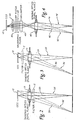
- the filter 5 will provide different photon rejection characteristics of the axial rays 20, 30. This is also true in the arrangement in Figure 3 .
- the filter 5 is behind the imaging optics 10. Because the pupil plane (i.e., the plane at which axial rays of all light beams cross) is in the center of the imaging optics 10, the axial ray passes through the imaging optics 10 without changing direction.
- the filter 5 in Figure 3 like the filter 5 in Figure 2 , will provide different photon rejection characteristics of the axial rays 20, 30. Accordingly, in both arrangements, the angular spectral dependence of the filter 5 results in a significant amount of excitation leakage that both limits the achievable SBR and is non-constant across the image.
- FIG. 4 is an illustration of the arrangement disclosed in Hwang et al. As shown in Figure 4 , a collimator 40 is placed between imaging optics 45 and band-pass and holographic filters 50, 55. (Hwang suggests the use of a holographic notch filter 55 to enhance the rejection capability of the band-pass filter 50.) A lens 60 focuses the light beams passing through the filters 50, 55 onto a CCD detector 65.
- the collimator 40 causes the rays of each of the light beams to exit the collimator 40 parallel to each other.
- the field of view is a single point that provides an axial ray 70 through the filters 50, 55 at a 0 degree angle
- other rays of the same light beam 75 will also pass through the filters 50, 55 at a 0 degree angle because of the effect of the collimator 40.
- a light beam 80 emanating from the edge of the field, while still collimated traverses the filters 50, 55 at an angle.
- the pupil plane is in the center of the imaging optics 45, and the axial ray 85 of light beam 80 passes through the imaging optics 45 without changing direction. Accordingly, light from different field points enter the filters 50, 55 at different angles and, therefore, results in different amounts of excitation leakage across the field.
- FIG. 5 is an illustration of a detector system 100 of a preferred embodiment that minimizes field dependence and maximizes the Signal to Background Ratio (SBR) performance of spectral filtering.
- the detector system 100 comprises a light detector 105 (such as a CCD), imaging optics 110 with an equivalent focal length F, a set of filters 115 positioned between the light detector 105 and the imaging optics 110, and an aperture 120 located at a front focal plane of the imaging optics 110.
- the term "imaging optics” refers to one or more optical elements whose function collectively is to project a scene onto a detector (e.g., a sensor array) such as a CCD camera.
- Imaging optics can comprise a single lens if its placement allows it to project the picture of a given scene onto the detector. Imaging optics can also comprise two or more lenses together in such a way that they all work together to produce the same function (i.e., project the image of a scene onto a detector).
- imaging optics can be used interchangeably with the terms “imaging lens” and “imaging lens assembly.” Further, imaging optics can include components other than lenses (e.g., mirrors).
- a "set" can include one or more than one member. Accordingly, a set of filters, for example, can contain a single filter or a plurality of filters. In this way, one can stack one or more filters to achieve the desired background rejection.
- the pupil plane i.e., the plane at which axial rays of all light beams cross
- the pupil plane is not in the center of the imaging optics 110, and axial rays that hit the imaging optics 110 at non-0 degree angles will change direction when exiting the imaging optics 110.
- the pupil aperture 120 located at a front focal plane of the imaging optics 110 the pupil plane is in the front focal plane of the imaging optics 110, and a telecentric space is created between the imaging optics 110 and the light detector 105.
- each of the axial rays will receive the same filtering from the set of filters 115. While the non-axial rays of each light beam will hit the set of filters 115 at non-0 degree angles and, hence, be subject to varying filtering effects due to the angular dependence problem, such rays from each light beam will see the same effect.
- Figure 6 is an illustration of a detector system 200 of another preferred embodiment.
- This system 200 is similar to the system 100 in Figure 5 , and common components are labeled the same.
- the system 200 in Figure 6 has an additional set of filters 210 in front of the imaging optics 110.
- the set of filters 210 comprises one or more dichroic filters.
- This system 200 takes advantage of the fact that rays that traverse a filter placed in front of imaging optics at large angles will traverse a filter placed behind the imaging optics at smaller angles and vise versa. This has the effect of balancing out any residual leakage and, thus, flattening the field.
- the additional set of filters 210 in front of the imaging optics 110, the angular effect from the first set of filters 115 is balanced out more evenly across the field.
- the additional set of filters 210 in this embodiment is located on a filter wheel 230 comprising at least one additional set of filters (not shown).
- the set of filters 115 can be placed in a filter wheel 240 comprising at least one additional set of filters (not shown). This allows different "colors" of filters to image different labels.
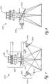
- FIG. 7 is an illustration of a fluorescence filtering system 300 of another preferred embodiment.
- This system 300 comprises a source subsystem 310 comprising two light sources 320, 330, each with a set of filters 340, 350 designed to pass wavelengths of light in an absorption band of a fluorescent material. (As discussed above, a filter may leak wavelengths of light in other bands.)
- the system 300 also comprises a detector subsystem 360, identical to the detector system 200 in Figure 6 (components are labeled the same).
- rejection performance of the set of excitation filters 340, 350 in the excitation paths matches the rejection performance of the set of emission filters 115.
- the rejection by both the set of excitation and emission filters 115, 340, 350 is preferably matched so that leakage from the set of excitation filters 340, 350 in the emission band will have the same effect as a comparable leakage from the set of emission filters 115 in the excitation band.
- Figure 7 shows two light sources 320, 330, three or more light sources can be used.
- the number of light sources does not have to match the number of sets of filters. For example, one can use one light source with one filter set and then split the output to act like separate sources. Alternatively, one can split the output to more than one port and put filter sets in front of each port.
- FIG 8 is an illustration of an alternate system 400, in which a single source 410 is used with a dichoric splitter 420.
- the dichroic splitter 420 is positioned such that light from the light source 410 illuminates a target and light emitted from the target reaches the detector 430.
- the dichroic splitter 420 also has filtering properties like the set of filters 210 in Figures 6 and 7 .
- the advantage of using the set of filters 210 in Figures 6 and 7 is that they prevents any possible specular reflections from getting into the collection optics.
- the detector is a Hamamatsu ORCA_AG detector
- the imaging optics 110 is a Canon 50mm/ F2.0 lens
- the set of emission filters 115 are Omega 822DF20 filters
- the second set of filters 210 is a Semrock 800LP filter, operating at a nominal zero-degree angle of incidence.
- the excitation sources preferably consist of two fiber-coupled, symmetrically-positioned identical laser diode sources (782nm) as the light sources 320, 300 and a set of two excitation filters 340, 350 in front of each laser 320, 330. Both excitation and emission filters have about OD6 rejection each.
- Figure 9 is a graph showing transmission curves for the excitation and emission filters.
- Figure 10 shows the same data in log scale so that the rejection level can be better evaluated. Tests were conducted to confirm that rejection with a configuration of (2, 2) excitation and emission filter sets is better than (1, 1), (1, 2), and (2, 1) configurations. Of course, if further rejection is needed, one can use (3, 3), (4, 4), etc.
- Figure 11 is a graph showing reduction in residual leakage from the filtering architecture shown in Figure 7 . A comparison between Figures 10 and 11 show the theoretical level of reduction in background leakage that can be achieved by doubling the rejection capability of both the excitation and emission filters.
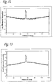
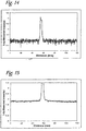
- Figures 12-15 show horizontal cross-sections from images obtained with the prototype system described above.
- the target is a nitro-cellulose membrane with 5 IRDye ® 800 labeled fluorescent spots.
- the membrane produces a significant amount of scattering from the excitation laser and is thus used to obtain a measure of the rejection capability of the filters and the flatness of the residual background.
- the cross-section is arbitrarily chosen to pass through a fluorescent spot located near the center of the image. Such fluorescent spot is used to measure the fluorescence transmission efficiency. This way, a measure of Signal-to-Background (SBR) can easily be obtained.
- SBR Signal-to-Background
- the graph is displayed in log-scale in order to enhance the levels of the background.
- Figures 12 and 13 only one emission filter was placed in front and in the back of the lens, respectively. This is similar to what is done in most prior small animal imaging solutions. It also shows how the non-flatness of the background in both cases complements each other, and, therefore, by placing filters on both sides of the lens, a more balanced rejection is obtained.
- Figures 14 and 15 show the image with filters configured according to the preferred embodiment of Figure 7 .
- the exposure time is increased to 120s in order to enhance the detection of any residual background leakage. As is clear from the image, even though the fluorescent signal is much higher than saturation, the leakage is still flat and non-significant.
- the SBR improvement in this case is estimated to be ⁇ 30x.
- each of the excitation filter sets can pass wavelengths in more than one excitation band
- emission filter sets can pass wavelengths in more that one emission band.
- any of the sets of filters disclosed herein can be placed on a filter wheel.
Landscapes
- Health & Medical Sciences (AREA)
- Chemical & Material Sciences (AREA)
- Immunology (AREA)
- Physics & Mathematics (AREA)
- Life Sciences & Earth Sciences (AREA)
- Analytical Chemistry (AREA)
- Biochemistry (AREA)
- General Health & Medical Sciences (AREA)
- General Physics & Mathematics (AREA)
- Nuclear Medicine, Radiotherapy & Molecular Imaging (AREA)
- Pathology (AREA)
- Chemical Kinetics & Catalysis (AREA)
- Optics & Photonics (AREA)
- Investigating, Analyzing Materials By Fluorescence Or Luminescence (AREA)
Description
- A fluorescence optical system illuminates a fluorophore-labeled target with light whose wavelength content falls within the absorption band and collects light whose wavelength content is in the emission band. An emission filter placed in front of a detector filters light that is not in the emission band. One challenge with emission filters is that unwanted photon rejection depends on the angle at which light traverses the filter. Specifically, as the angle of incidence increases, the transmission/reflection of the filter shifts to lower wavelengths. Accordingly, even if the field of view is a single point that provides an axial ray at a 0 degree angle, other rays of the same light beam will pass through the filter at non-0 degree angles and, accordingly, may experience different amounts of filtering.
- This situation is addressed in Hwang et al., "The influence of improved interference filter performance for molecular imaging using frequency domain photon migration measurements," Optical Tomography and Spectroscopy of Tissue VI, SPIE vol. 5693, pp. 503-512. Hwang et al. describes an optical system in which a collimator is placed between imaging optics and an emission filter. The collimator ensures that all rays in a light beam originating from a certain point in the image field will pass through the filter at a 0 degree angle and, thus, will receive the same type of filtering. However, if a relatively large field of view is used, light beams emanating from the edge of the field, while still collimated, will pass through the filter at an angle. This results in different amounts of excitation leakage across the field.
- There is a need, therefore, for a fluorescence filtering method and system that will overcome this problem.
- In
US 5 206 699 A diamonds are detected by passing the emitted radiation through a narrow band pass filter and sensing the Raman radiation with a photo-multiplier tube. In front of the photo-multiplier tube a filter is positioned and in front of the filter a lens. - In
US 5 943 129 A a system is disclosed comprising a light source, a filter that transmits light of a selected spectral range. The light passing the filter is directed onto a sample that is capable of responsively fluorescing and emitting light when so illuminated. A light detector is provided with in front of the light detector a lens and in front of the lens a filter. -
US2004/125370 A1 discloses a device for optical examination of biological material arranged to illuminate a specific pixel by focusing excitation light and analyzing the light emitted from this pixel using a detector. The full field of view of the biological material is screened by moving the table onto which is applied the biological material. -
US 6,345,115 B1 discloses an imaging system where the field of view is illuminated using a ring light system in order to maximize the light transfer from the lens to the light detector. To that purpose, an object telecentric space is created. - The present invention is defined by the following claims.
- By way of introduction, it is disclosed a method for fluorescence filtering and a fluorescence filtering system for molecular imaging comprising a source subsystem comprising a light source and a set of excitation filters designed to pass wavelengths of light in an absorption band of a fluorescent material. A detector system is also disclosed comprising a light detector, imaging optics, a first set of filters designed to pass wavelengths of light in an emission band of the fluorescent material, and an aperture located at a front focal plane of the imaging optics. A telecentric space is created between the light detector and the imaging optics, such that axial rays from a plurality of field points emerge from the imaging optics parallel to each other and perpendicular to the first set of filters. Other preferred embodiments are provided, and each of the preferred embodiments described herein can be used alone or in combination with one another within the scope of the appended claims.
- The preferred embodiments will now be described with reference to the attached drawings.
-
-
Figures 1A and 1B are graphs showing wavelength shifting of a band-pass filter due to incident angular variation. -
Figure 2 is an illustration of an optical arrangement in which an emission filter is placed in front of imaging optics. -
Figure 3 is an illustration of an optical arrangement in which an emission filter is placed between the imaging optics and a detector. -
Figure 4 is an illustration of an optical arrangement using a collimator. -
Figure 5 is an illustration of a detector system of a preferred embodiment. -
Figure 6 is an illustration of a detector system with a filter wheel of a preferred embodiment. -
Figure 7 is an illustration of a fluorescence filtering system of a preferred embodiment. -
Figure 8 is an illustration of a fluorescence filtering system of another preferred embodiment. -
Figure 9 is a graph of transmission curves for excitation and emission filters of a preferred embodiment. -
Figure 10 is a graph showing the same data as inFigure 9 but in log scale. -
Figure 11 is a graph showing reduction in residual leakage using the filtering architecture shown inFigure 7 . -
Figure 12 is a graph showing a horizontal cross-section from a fluorescence image obtained with a prototype system of a preferred embodiment with one band-pass filter placed in front of the lens at T = 5 s. -
Figure 13 is a graph showing a horizontal cross-section from a fluorescence image obtained with a prototype system of a preferred embodiment with one band-pass filter placed behind the lens at T = 5 s. -
Figure 14 is a graph showing a horizontal cross-section from a fluorescence image obtained with a prototype system of a preferred embodiment at T = 5 s. -
Figure 15 is a graph showing a horizontal cross-section from a fluorescence image obtained with a prototype system of a preferred embodiment at T = 120 s. - Fluorescence detection is a tool for molecular imaging. It enables researchers to detect particular components of complex bio-molecular assemblies, such as in live cells. Fluorescence is a photo-physical process that involves the interaction of light with certain molecules called fluorophores or fluorescent dyes. It consists of the absorption of light energy at the appropriate wavelength by such molecules and the subsequent emission of other light photons at longer wavelengths. The wavelength ranges that a fluorophore molecule can absorb and emit at are called absorption and emission bands, respectively.
- A fluorescence optical system illuminates a fluorophore-labeled target with light whose wavelength content falls within the absorption band and collects light whose wavelength content is in the emission band. The source(s) and optics that generate the illumination part of the system are called the "excitation optics," and the optics used to collect the fluorescence emission are called the "emission optics." Since it is rarely possible to find a light source that has a spectral content (i.e., wavelength range) that exactly matches every fluorophore absorption band, special optical filters (usually band-pass filters) are used along with the light sources to limit the range of illuminating wavelengths to that of the absorption band and not the emission band. At the same time, other filters are used in the emission path to allow light with wavelengths in the emission band only to reach the detector.
- The task of a fluorescence optical system design is to make sure that photons with wavelengths in the absorption band only reach the target, and photons with wavelengths in the emission band only reach the detector. If not, photons from the light source will wrongly be considered as fluorescence, and, therefore, a wrong measure of the amount of fluorophore dye results. This can be a tough task if the amount of emitted fluorescence is much less than the amount of excitation light scattered by the target surface (i.e., not absorbed). This is usually the case for in-vivo imaging, such as in small animal imaging, since there are a number of challenges to achieving good signal-to-noise performance when imaging fluorescence targets deep inside small animals.
- One challenge is that the amount of excitation light that reaches the inside of an animal is usually quite low because of the significant absorption and scattering caused by the various body parts (skin, muscle, fat, bone, etc.). For example, the transmission through "shaved skin + fat layer + whole rib cage + abdominal wall" is in the order of 10-6 and varies with the thickness and composition of each of those parts. The emitted fluorescence will have to traverse a comparable tissue path back up towards the detection system. Thus, the level of fluorescence is <<10-12 times that of the excitation signal. So, for example, if a flux density of 1mW/cm2 impinges upon the outside of a mouse or other small animal, only a sub-nano Watt optical signal actually reaches dye-labeled cells inside the abdomen, and, in turn, only sub-femto Watt of fluorescence signal reaches the detector. The low amount of emitted fluorescence is further reduced by absorption and scattering as it makes its way out towards the detector. This means that the scattering from the excitation light that occurs at the outer parts of the animal can cause much higher levels than the fluorescence signal itself. At the same time, existing optical filter technology (e.g., thin-film emission filters, such as multi-cavity designs) can, at best, provide rejection of unwanted photons only in the order of OD6 (10-6). So, standard fluorescence methods would allow through high non-fluorescent background levels and, in turn, result in low Signal-to-Background (SBR) and Signal-to-Noise (SNR) ratios.
- Another challenge is that unwanted photon rejection also depends on the angle at which light traverses the filter, as the spectral properties of optical thin film filters vary with the angle of incidence of light. Specifically, as the angle of incidence increases, the transmission/reflection of the filter shifts to lower wavelengths ("blue shift"). This shift can be described by

n is the effective index of refraction of the thin-film. The value ofn is typically in the range of 1.5 to 2.5 and varies with polarization. -
Figures 1A and 1B are graphs (transmission and transmission (dB), respectively) showing wavelength shifting of a band-pass filter due to a varying angle of incidence (0, 10, and 20 degrees). As shown in these graphs, as the angle of collected light increases relative to the normal to the filter, the effective transmission band shifts to lower wavelengths, and the amounts of transmitted fluorescence and background signals change accordingly. Light from the target spans a significant range of field angles when a relatively large field of view is imaged, such as in the case of small animal imaging. Therefore, in small animal imaging where a relatively large field of view is imaged, the resulting emission filtering (i.e., transmitted SBR) is non-constant across the image. Accordingly, it is desired to use special spectral filtering solutions in order to improve the rejection of non-fluorescence light across the whole field of view (i.e., where light is collected at different angles). - Many current area fluorescence imaging techniques use the same excitation and emission filters designed for microscopy and scanning systems and use arrangements where the
emission filter 5 is placed in front of the imaging optics 10 (as inFigure 2 ) or behind it (as inFigure 3 , where theemission filter 5 is between theimaging optics 10 and the detector 15 (here, a CCD)). (The horizontal lines from which the emission is originating in these and other figures herein represent a target, such as mouse or other small animal.) These filters are typically multi-cavity interference filters optimized for maximum rejection in the excitation band and maximum transmission in the emission band. As discussed earlier, the spectral properties of such filters vary with the angle of incidence of light. Because, inFigure 2 , the axial ray 20 (i.e., the "chief' or center ray of a light beam) oflight beam 25 is at a 0 degree angle to thefilter 5, while theaxial ray 30 oflight beam 35 is at about a 45 degree angle to thefilter 5, thefilter 5 will provide different photon rejection characteristics of theaxial rays Figure 3 . InFigure 3 , thefilter 5 is behind theimaging optics 10. Because the pupil plane (i.e., the plane at which axial rays of all light beams cross) is in the center of theimaging optics 10, the axial ray passes through theimaging optics 10 without changing direction. Accordingly, thefilter 5 inFigure 3 , like thefilter 5 inFigure 2 , will provide different photon rejection characteristics of theaxial rays filter 5 results in a significant amount of excitation leakage that both limits the achievable SBR and is non-constant across the image. - It should be noted that, even in the instance where the
axial ray 20 passes through thefilter 5 at a 0 degree angle, other rays of thelight beam 25 pass through thefilter 5 at a non-0 degree angle. Accordingly, even if the field of view is a single point that provides an axial ray at a 0 degree angle, other rays of the same light beam will pass through thefilter 5 at non-0 degree angles and, accordingly, may experience different amounts of filtering by thefilter 5 due to the angular spectral dependence problem. - This situation is addressed in Hwang et al., "The influence of improved interference filter performance for molecular imaging using frequency domain photon migration measurements," Optical Tomography and Spectroscopy of Tissue VI, SPIE vol. 5693, pp. 503-512.
Figure 4 is an illustration of the arrangement disclosed in Hwang et al. As shown inFigure 4 , acollimator 40 is placed between imaging optics 45 and band-pass andholographic filters holographic notch filter 55 to enhance the rejection capability of the band-pass filter 50.) Alens 60 focuses the light beams passing through thefilters CCD detector 65. Thecollimator 40 causes the rays of each of the light beams to exit thecollimator 40 parallel to each other. As a result, unlike the situation noted above, if the field of view is a single point that provides anaxial ray 70 through thefilters same light beam 75 will also pass through thefilters collimator 40. However, as shown inFigure 4 , if a relatively large field of view is used, alight beam 80 emanating from the edge of the field, while still collimated, traverses thefilters axial ray 85 oflight beam 80 passes through the imaging optics 45 without changing direction. Accordingly, light from different field points enter thefilters -
Figure 5 is an illustration of adetector system 100 of a preferred embodiment that minimizes field dependence and maximizes the Signal to Background Ratio (SBR) performance of spectral filtering. Thedetector system 100 comprises a light detector 105 (such as a CCD),imaging optics 110 with an equivalent focal length F, a set offilters 115 positioned between thelight detector 105 and theimaging optics 110, and anaperture 120 located at a front focal plane of theimaging optics 110. As used herein, the term "imaging optics" refers to one or more optical elements whose function collectively is to project a scene onto a detector (e.g., a sensor array) such as a CCD camera. Imaging optics can comprise a single lens if its placement allows it to project the picture of a given scene onto the detector. Imaging optics can also comprise two or more lenses together in such a way that they all work together to produce the same function (i.e., project the image of a scene onto a detector). The term "imaging optics" can be used interchangeably with the terms "imaging lens" and "imaging lens assembly." Further, imaging optics can include components other than lenses (e.g., mirrors). As also used herein, a "set" can include one or more than one member. Accordingly, a set of filters, for example, can contain a single filter or a plurality of filters. In this way, one can stack one or more filters to achieve the desired background rejection. - By locating the
aperture 120 in front of theimaging optics 110, the pupil plane (i.e., the plane at which axial rays of all light beams cross) is not in the center of theimaging optics 110, and axial rays that hit theimaging optics 110 at non-0 degree angles will change direction when exiting theimaging optics 110. Further, because thepupil aperture 120 located at a front focal plane of theimaging optics 110, the pupil plane is in the front focal plane of theimaging optics 110, and a telecentric space is created between theimaging optics 110 and thelight detector 105. This will cause the axial rays from a plurality of field points (i.e., locations in the imaged target) to emerge from theimaging optics 110 parallel to each other and perpendicular (i.e., at a 0-degree angle) to the set offilters 115. (A telecentric approach also eliminates otherwise unavoidable ghost images when the set offilters 115 comprises more than one filter.) As a result, each of the axial rays will receive the same filtering from the set offilters 115. While the non-axial rays of each light beam will hit the set offilters 115 at non-0 degree angles and, hence, be subject to varying filtering effects due to the angular dependence problem, such rays from each light beam will see the same effect. In other words, in the telecentric space, all the field points (light emanating from different parts of the image) traverse the set offilters 115 in the same manner, centered around the zero-degree angle. This minimizes the angular variation across the field and, thus, the resulting spectral filtering variation. Accordingly, unlike with the optical arrangement inFigure 4 , light from different field points entering the set offilters 115 at different angles will result in substantially the same amount of excitation leakage across the field. -
Figure 6 is an illustration of adetector system 200 of another preferred embodiment. Thissystem 200 is similar to thesystem 100 inFigure 5 , and common components are labeled the same. However, thesystem 200 inFigure 6 has an additional set offilters 210 in front of theimaging optics 110. Preferably, the set offilters 210 comprises one or more dichroic filters. Thissystem 200 takes advantage of the fact that rays that traverse a filter placed in front of imaging optics at large angles will traverse a filter placed behind the imaging optics at smaller angles and vise versa. This has the effect of balancing out any residual leakage and, thus, flattening the field. Therefore, by placing the additional set offilters 210 in front of theimaging optics 110, the angular effect from the first set offilters 115 is balanced out more evenly across the field. Although not necessary, the additional set offilters 210 in this embodiment is located on afilter wheel 230 comprising at least one additional set of filters (not shown). Similarly, the set offilters 115 can be placed in afilter wheel 240 comprising at least one additional set of filters (not shown). This allows different "colors" of filters to image different labels. - Turning again to the drawings,
Figure 7 is an illustration of afluorescence filtering system 300 of another preferred embodiment. Thissystem 300 comprises asource subsystem 310 comprising twolight sources filters system 300 also comprises adetector subsystem 360, identical to thedetector system 200 inFigure 6 (components are labeled the same). Preferably, rejection performance of the set ofexcitation filters detector 105 responds to all the photons that pass through the excitation as well the emission bands, the rejection by both the set of excitation andemission filters excitation filters emission filters 115 in the excitation band. It should be noted that, whileFigure 7 shows twolight sources -
Figure 8 is an illustration of analternate system 400, in which asingle source 410 is used with adichoric splitter 420. Thedichroic splitter 420 is positioned such that light from thelight source 410 illuminates a target and light emitted from the target reaches thedetector 430. Thedichroic splitter 420 also has filtering properties like the set offilters 210 inFigures 6 and7 . However, the advantage of using the set offilters 210 inFigures 6 and7 is that they prevents any possible specular reflections from getting into the collection optics. - In one presently preferred embodiment of the
system 300 shown inFigure 7 , the detector is a Hamamatsu ORCA_AG detector, theimaging optics 110 is a Canon 50mm/ F2.0 lens, the set ofemission filters 115 are Omega 822DF20 filters, and the second set offilters 210 is a Semrock 800LP filter, operating at a nominal zero-degree angle of incidence. The excitation sources preferably consist of two fiber-coupled, symmetrically-positioned identical laser diode sources (782nm) as thelight sources excitation filters laser - Turning again to the drawings,
Figure 9 is a graph showing transmission curves for the excitation and emission filters.Figure 10 shows the same data in log scale so that the rejection level can be better evaluated. Tests were conducted to confirm that rejection with a configuration of (2, 2) excitation and emission filter sets is better than (1, 1), (1, 2), and (2, 1) configurations. Of course, if further rejection is needed, one can use (3, 3), (4, 4), etc.Figure 11 is a graph showing reduction in residual leakage from the filtering architecture shown inFigure 7 . A comparison betweenFigures 10 and 11 show the theoretical level of reduction in background leakage that can be achieved by doubling the rejection capability of both the excitation and emission filters. -
Figures 12-15 show horizontal cross-sections from images obtained with the prototype system described above. The target is a nitro-cellulose membrane with 5 IRDye®800 labeled fluorescent spots. The membrane produces a significant amount of scattering from the excitation laser and is thus used to obtain a measure of the rejection capability of the filters and the flatness of the residual background. The cross-section is arbitrarily chosen to pass through a fluorescent spot located near the center of the image. Such fluorescent spot is used to measure the fluorescence transmission efficiency. This way, a measure of Signal-to-Background (SBR) can easily be obtained. In each figure, the graph is displayed in log-scale in order to enhance the levels of the background. - In
Figures 12 and 13 , only one emission filter was placed in front and in the back of the lens, respectively. This is similar to what is done in most prior small animal imaging solutions. It also shows how the non-flatness of the background in both cases complements each other, and, therefore, by placing filters on both sides of the lens, a more balanced rejection is obtained.Figures 14 and 15 show the image with filters configured according to the preferred embodiment ofFigure 7 . InFigure 15 , the exposure time is increased to 120s in order to enhance the detection of any residual background leakage. As is clear from the image, even though the fluorescent signal is much higher than saturation, the leakage is still flat and non-significant. The SBR improvement in this case is estimated to be ~ 30x. - There are several alternatives that can be used with these disclosures. For example, while the preferred invention illustrated above with respect to an application for fluorescence filtering for molecular imaging, these arrangements can be used in any suitable application. Accordingly, the filters do not have to be designed to pass wavelengths of light in absorption and emission bands of fluorescent materials. Also, while these disclosures were illustrated in terms of imaging a small animal, such as a mouse, they can be used to image other targets. Additionally, any suitable light source, detector, filter, imaging optics, and aperture can be used. Further, any of the embodiments disclosed herein can be used by itself or in combination with any of the other embodiments disclosed herein. Finally, each of the excitation filter sets can pass wavelengths in more than one excitation band, and emission filter sets can pass wavelengths in more that one emission band. Also, any of the sets of filters disclosed herein can be placed on a filter wheel.
- The foregoing detailed description is to be understood as an illustration of selected forms that the invention can take and not as a definition of the invention. The following claims, including all equivalents, define the scope of this invention.
Claims (15)
- A detector system comprising:• a light detector (105);• imaging optics (110);• a first set of filters (115), designed to pass wavelength of light in an emission band of a fluorescent material, positioned between the light detector and the imaging optics;characterized in that• an aperture (120) is located at a front focal plane (F) of the imaging optics (110), wherein a telecentric space is created between the light detector (105) and the imaging optics (110), such that non-parallel axial rays from a plurality of field points emerge from the imaging optics parallel to each other and perpendicular to the first set of filters.
- The detector system of claim 1, wherein a second set of filters (210) is located on the opposite side of the imaging optics compared to the first set of filters (115).
- The detector system of Claim 2, wherein the second set of filters (210) comprises a dichroic filter.
- The detector system of Claim 2 or 3, wherein the second set of filters (210) is located on a filter wheel (230) comprising at least one additional set of filters.
- A fluorescence filtering system comprising:
a source subsystem (310) comprising:• a light source (320, 330); and• a set of excitation filters (340, 350) designed to pass wavelengths of light in an absorption band of a fluorescent material; and• a detector system (360) according to claim 1. - The fluorescence filtering system of Claim 5, wherein rejection performance of the set of excitation filters (340, 350) matches rejection performance of the first set of filters (115).
- The fluorescence filtering system of Claim 5 or 6 further comprising a dichroic splitter (420) between the light source (410) and the detector (430), the dichroic splitter positioned such that light from the light source illuminates a target and light emitted from the target reaches the detector.
- A method for fluorescence filtering, the method comprising:(a) illuminating a target comprising a fluorescent material with light in an absorption band of the fluorescent material, wherein, in response to absorbing the light in the absorption band, the fluorescent material emits light in an emission band of the fluorescent material;(b) causing non-parallel axial rays of light beams from a plurality of field points in the target, after passing through an aperture located at a front focal plane of an imaging optics, to emerge from the imaging optics (110) parallel to each other and perpendicular to a first set of filters designed (115) to pass wavelengths of light in the emission band and(c) detecting light passed through the first set of filters (115).
- The method of Claim 8 further comprising, before (a), passing light from a light source (320, 330) through a set of excitation filters (340, 350) designed to pass light in the absorption band.
- The method of Claim 9, wherein rejection performance of the first set of filters (115) designed to pass wavelengths of light in the emission band matches rejection performance of the set of excitation filters (340, 350) designed to pass wavelengths of light in the absorption band.
- The method of Claim 10, further comprising, between (a) and (b), passing the light emitted from the fluorescent material through a second set of filters (210) designed to pass wavelength of light in the emission band.
- The method of claim 11, wherein the second set of filters (210) comprises a dichroic filter.
- The method of Claim 11 or 12, wherein the second set of filters (210) are located on a filter wheel (230) comprising at least one additional set of filters.
- The method according to any of Claims 11 to 13, wherein (a) is performed by a single light source.
- The method according to any of Claims 11 to 13, wherein (a) is performed by two or more light sources.
Applications Claiming Priority (2)
| Application Number | Priority Date | Filing Date | Title |
|---|---|---|---|
| PCT/US2006/005341 WO2007094782A1 (en) | 2006-02-15 | 2006-02-15 | Fluorescence filtering system and method for molecular imaging |
| US11/355,848 US7286232B2 (en) | 2006-02-15 | 2006-02-15 | Fluorescence filtering system and method for molecular imaging |
Publications (3)
| Publication Number | Publication Date |
|---|---|
| EP1989531A1 EP1989531A1 (en) | 2008-11-12 |
| EP1989531A4 EP1989531A4 (en) | 2013-10-16 |
| EP1989531B1 true EP1989531B1 (en) | 2022-01-05 |
Family
ID=42734761
Family Applications (1)
| Application Number | Title | Priority Date | Filing Date |
|---|---|---|---|
| EP06720779.5A Expired - Lifetime EP1989531B1 (en) | 2006-02-15 | 2006-02-15 | Fluorescence filtering system and method for molecular imaging |
Country Status (5)
| Country | Link |
|---|---|
| US (1) | US7286232B2 (en) |
| EP (1) | EP1989531B1 (en) |
| JP (1) | JP2009526993A (en) |
| CA (1) | CA2640441C (en) |
| WO (1) | WO2007094782A1 (en) |
Families Citing this family (22)
| Publication number | Priority date | Publication date | Assignee | Title |
|---|---|---|---|---|
| US7211414B2 (en) | 2000-12-01 | 2007-05-01 | Visigen Biotechnologies, Inc. | Enzymatic nucleic acid synthesis: compositions and methods for altering monomer incorporation fidelity |
| US7668697B2 (en) | 2006-02-06 | 2010-02-23 | Andrei Volkov | Method for analyzing dynamic detectable events at the single molecule level |
| WO2009115945A1 (en) * | 2008-03-20 | 2009-09-24 | Koninklijke Philips Electronics N.V. | Photo-detector and method of measuring light |
| JP4711009B2 (en) * | 2008-10-16 | 2011-06-29 | ソニー株式会社 | Optical measuring device |
| US8982349B2 (en) | 2010-03-31 | 2015-03-17 | Konica Minolta Optics, Inc. | Measuring optical system, and color luminance meter and colorimeter using the same |
| US8681247B1 (en) * | 2010-05-12 | 2014-03-25 | Li-Cor, Inc. | Field flattening correction method for fluorescence imaging system |
| US8743241B2 (en) | 2010-05-12 | 2014-06-03 | Li-Cor, Inc. | Wide dynamic range imaging |
| US8436321B2 (en) | 2010-05-21 | 2013-05-07 | Li-Cor, Inc. | Optical background suppression systems and methods for fluorescence imaging |
| FR2964458B1 (en) * | 2010-09-06 | 2012-09-07 | Commissariat Energie Atomique | HIGH-RESOLUTION CARTOGRAPHY AND ANALYSIS DEVICE FOR ELEMENTS IN SOLIDS |
| US9134241B2 (en) | 2011-04-11 | 2015-09-15 | Li-Cor, Inc. | Differential scan imaging systems and methods |
| JP5937799B2 (en) * | 2011-09-28 | 2016-06-22 | 株式会社トプコン | Spectral image acquisition device |
| WO2014197786A2 (en) | 2013-06-06 | 2014-12-11 | Kintz Gregory J | Apparatus and methods for detecting optical signals from implanted sensors |
| US9541750B2 (en) * | 2014-06-23 | 2017-01-10 | Li-Cor, Inc. | Telecentric, wide-field fluorescence scanning systems and methods |
| JP6585728B2 (en) | 2015-02-23 | 2019-10-02 | リ−コール,インコーポレイティド | Biopsy specimen fluorescence imaging apparatus and method |
| WO2016210340A1 (en) | 2015-06-26 | 2016-12-29 | Li-Cor, Inc. | Fluorescence biopsy specimen imager and methods |
| US10489964B2 (en) | 2016-04-21 | 2019-11-26 | Li-Cor, Inc. | Multimodality multi-axis 3-D imaging with X-ray |
| WO2017223378A1 (en) | 2016-06-23 | 2017-12-28 | Li-Cor, Inc. | Complementary color flashing for multichannel image presentation |
| US10993622B2 (en) | 2016-11-23 | 2021-05-04 | Li-Cor, Inc. | Motion-adaptive interactive imaging method |
| CN110100172B (en) * | 2016-12-21 | 2021-12-24 | Lg电子株式会社 | Planktonic microorganism measuring device and air conditioning device including same |
| WO2018200261A1 (en) | 2017-04-25 | 2018-11-01 | Li-Cor, Inc. | Top-down and rotational side view biopsy specimen imager and methods |
| JP7098146B2 (en) | 2018-07-05 | 2022-07-11 | 株式会社Iddk | Microscopic observation device, fluorescence detector and microscopic observation method |
| US10667693B1 (en) * | 2018-11-16 | 2020-06-02 | Perkinelmer Health Sciences, Inc. | Systems, methods, and apparatus for interference filter correction based on angle of incidence |
Citations (3)
| Publication number | Priority date | Publication date | Assignee | Title |
|---|---|---|---|---|
| US6345115B1 (en) * | 1997-08-07 | 2002-02-05 | Imaging Research, Inc. | Digital imaging system for assays in well plates, gels and blots |
| US20030086624A1 (en) * | 2001-11-08 | 2003-05-08 | Garcia Kevin J. | Ghost image correction system and method |
| WO2005114643A2 (en) * | 2004-05-21 | 2005-12-01 | Silicon Light Machines Corporation | Optical positioning device using telecentric imaging |
Family Cites Families (15)
| Publication number | Priority date | Publication date | Assignee | Title |
|---|---|---|---|---|
| US3641344A (en) * | 1969-04-01 | 1972-02-08 | Perkin Elmer Corp | Solar-stimulated fluorescent radiation detection method and apparatus |
| US5206699A (en) * | 1988-05-06 | 1993-04-27 | Gersan Establishment | Sensing a narrow frequency band of radiation and gemstones |
| JPH02300616A (en) * | 1989-05-15 | 1990-12-12 | Nissan Motor Co Ltd | Measuring instrument |
| US5943129A (en) * | 1997-08-07 | 1999-08-24 | Cambridge Research & Instrumentation Inc. | Fluorescence imaging system |
| JP3682834B2 (en) * | 1998-12-01 | 2005-08-17 | ホーチキ株式会社 | Optical device using wavelength tunable interference filter |
| JP2000230902A (en) * | 1999-02-12 | 2000-08-22 | Fuji Photo Film Co Ltd | Image forming apparatus |
| US6252664B1 (en) | 1999-10-15 | 2001-06-26 | Biocrystal Ltd. | Fluorescence filter cube for fluorescence detection and imaging |
| CA2392228A1 (en) * | 1999-11-19 | 2001-05-25 | Ming Xiao | Compact spectrofluorometer |
| EP1311824A4 (en) * | 2000-06-25 | 2010-12-08 | Affymetrix Inc | Optically active substrates |
| JP3741051B2 (en) * | 2001-05-10 | 2006-02-01 | 横河電機株式会社 | Biochip reader |
| US6856466B2 (en) * | 2001-07-05 | 2005-02-15 | Science & Engineering Associates, Inc. | Multiple imaging system |
| EP2315027A1 (en) * | 2002-08-16 | 2011-04-27 | Decision Biomarkers Incorporated | Substrates for isolating, reacting and microscopically analyzing materials |
| JP4037294B2 (en) * | 2003-03-20 | 2008-01-23 | オリンパス株式会社 | Method for determining the existence ratio of multiple intrinsic spectral components from spectral images |
| US7031084B2 (en) * | 2003-07-23 | 2006-04-18 | Eastman Kodak Company | Imaging system using combined dichroic/high-pass filters |
| US7295316B2 (en) * | 2004-01-14 | 2007-11-13 | Applera Corporation | Fluorescent detector with automatic changing filters |
-
2006
- 2006-02-15 WO PCT/US2006/005341 patent/WO2007094782A1/en not_active Ceased
- 2006-02-15 EP EP06720779.5A patent/EP1989531B1/en not_active Expired - Lifetime
- 2006-02-15 JP JP2008555208A patent/JP2009526993A/en active Pending
- 2006-02-15 CA CA2640441A patent/CA2640441C/en not_active Expired - Lifetime
- 2006-02-15 US US11/355,848 patent/US7286232B2/en not_active Expired - Lifetime
Patent Citations (3)
| Publication number | Priority date | Publication date | Assignee | Title |
|---|---|---|---|---|
| US6345115B1 (en) * | 1997-08-07 | 2002-02-05 | Imaging Research, Inc. | Digital imaging system for assays in well plates, gels and blots |
| US20030086624A1 (en) * | 2001-11-08 | 2003-05-08 | Garcia Kevin J. | Ghost image correction system and method |
| WO2005114643A2 (en) * | 2004-05-21 | 2005-12-01 | Silicon Light Machines Corporation | Optical positioning device using telecentric imaging |
Also Published As
| Publication number | Publication date |
|---|---|
| CA2640441A1 (en) | 2007-08-23 |
| US20070188760A1 (en) | 2007-08-16 |
| EP1989531A1 (en) | 2008-11-12 |
| CA2640441C (en) | 2015-11-24 |
| EP1989531A4 (en) | 2013-10-16 |
| US7286232B2 (en) | 2007-10-23 |
| WO2007094782A1 (en) | 2007-08-23 |
| JP2009526993A (en) | 2009-07-23 |
Similar Documents
| Publication | Publication Date | Title |
|---|---|---|
| CA2640441C (en) | Fluorescence filtering system and method for molecular imaging | |
| US20090080194A1 (en) | Fluorescence filtering system and method for molecular imaging | |
| US7420674B2 (en) | Method and arrangement for analyzing samples | |
| KR102600559B1 (en) | Multimodal fluorescence imaging flow cytometry system | |
| US7329860B2 (en) | Confocal imaging methods and apparatus | |
| US9046419B2 (en) | Systems and methods for spectrally encoded imaging | |
| EP3203215A1 (en) | Optical imaging spectroscopy of large-area samples | |
| JP5828440B1 (en) | Fine particle measuring device | |
| CN105806816A (en) | Detecting device and method for multichannel up-conversion luminescence | |
| JP2012521540A (en) | Sequential line scan encoded multicolor fluorescence microscopy and image flow cytometry | |
| US10520438B2 (en) | Collection optics system for spectrometer and Raman spectral system | |
| WO2009081969A1 (en) | Biological image acquisition device | |
| JP4533628B2 (en) | Subsurface autofluorescence spectrometer | |
| US8633432B2 (en) | Reflective focusing and transmissive projection device | |
| JP5551907B2 (en) | Method, microscope, and data storage carrier for imaging a sample using a microscope | |
| CN116249891A (en) | Method for detecting emitted light, detection device and laser scanning microscope | |
| CN107430263A (en) | Confocal inspection system with average illumination path and average collecting path | |
| KR20190024510A (en) | Collection optics system for spectrometer and Raman spectral system | |
| JP2005524069A (en) | Fluorescence detection apparatus and method having light emitting diode as excitation light source | |
| US20090306519A1 (en) | Measurement with multiplexed detection | |
| JP4983929B2 (en) | Biological image acquisition device | |
| JPH01316619A (en) | Spectrofluorescent device |
Legal Events
| Date | Code | Title | Description |
|---|---|---|---|
| PUAI | Public reference made under article 153(3) epc to a published international application that has entered the european phase |
Free format text: ORIGINAL CODE: 0009012 |
|
| 17P | Request for examination filed |
Effective date: 20080911 |
|
| AK | Designated contracting states |
Kind code of ref document: A1 Designated state(s): AT BE BG CH CY CZ DE DK EE ES FI FR GB GR HU IE IS IT LI LT LU LV MC NL PL PT RO SE SI SK TR |
|
| AX | Request for extension of the european patent |
Extension state: AL BA HR MK YU |
|
| A4 | Supplementary search report drawn up and despatched |
Effective date: 20130912 |
|
| RIC1 | Information provided on ipc code assigned before grant |
Ipc: G01N 21/64 20060101AFI20130906BHEP |
|
| STAA | Information on the status of an ep patent application or granted ep patent |
Free format text: STATUS: EXAMINATION IS IN PROGRESS |
|
| 17Q | First examination report despatched |
Effective date: 20170324 |
|
| GRAP | Despatch of communication of intention to grant a patent |
Free format text: ORIGINAL CODE: EPIDOSNIGR1 |
|
| STAA | Information on the status of an ep patent application or granted ep patent |
Free format text: STATUS: GRANT OF PATENT IS INTENDED |
|
| INTG | Intention to grant announced |
Effective date: 20210727 |
|
| GRAS | Grant fee paid |
Free format text: ORIGINAL CODE: EPIDOSNIGR3 |
|
| GRAA | (expected) grant |
Free format text: ORIGINAL CODE: 0009210 |
|
| STAA | Information on the status of an ep patent application or granted ep patent |
Free format text: STATUS: THE PATENT HAS BEEN GRANTED |
|
| AK | Designated contracting states |
Kind code of ref document: B1 Designated state(s): AT BE BG CH CY CZ DE DK EE ES FI FR GB GR HU IE IS IT LI LT LU LV MC NL PL PT RO SE SI SK TR |
|
| REG | Reference to a national code |
Ref country code: GB Ref legal event code: FG4D |
|
| REG | Reference to a national code |
Ref country code: CH Ref legal event code: EP |
|
| REG | Reference to a national code |
Ref country code: AT Ref legal event code: REF Ref document number: 1461011 Country of ref document: AT Kind code of ref document: T Effective date: 20220115 |
|
| REG | Reference to a national code |
Ref country code: DE Ref legal event code: R096 Ref document number: 602006060269 Country of ref document: DE |
|
| REG | Reference to a national code |
Ref country code: IE Ref legal event code: FG4D |
|
| REG | Reference to a national code |
Ref country code: LT Ref legal event code: MG9D |
|
| REG | Reference to a national code |
Ref country code: NL Ref legal event code: MP Effective date: 20220105 |
|
| PGFP | Annual fee paid to national office [announced via postgrant information from national office to epo] |
Ref country code: FR Payment date: 20220216 Year of fee payment: 17 |
|
| REG | Reference to a national code |
Ref country code: AT Ref legal event code: MK05 Ref document number: 1461011 Country of ref document: AT Kind code of ref document: T Effective date: 20220105 |
|
| PG25 | Lapsed in a contracting state [announced via postgrant information from national office to epo] |
Ref country code: NL Free format text: LAPSE BECAUSE OF FAILURE TO SUBMIT A TRANSLATION OF THE DESCRIPTION OR TO PAY THE FEE WITHIN THE PRESCRIBED TIME-LIMIT Effective date: 20220105 |
|
| PG25 | Lapsed in a contracting state [announced via postgrant information from national office to epo] |
Ref country code: SE Free format text: LAPSE BECAUSE OF FAILURE TO SUBMIT A TRANSLATION OF THE DESCRIPTION OR TO PAY THE FEE WITHIN THE PRESCRIBED TIME-LIMIT Effective date: 20220105 Ref country code: PT Free format text: LAPSE BECAUSE OF FAILURE TO SUBMIT A TRANSLATION OF THE DESCRIPTION OR TO PAY THE FEE WITHIN THE PRESCRIBED TIME-LIMIT Effective date: 20220505 Ref country code: LT Free format text: LAPSE BECAUSE OF FAILURE TO SUBMIT A TRANSLATION OF THE DESCRIPTION OR TO PAY THE FEE WITHIN THE PRESCRIBED TIME-LIMIT Effective date: 20220105 Ref country code: ES Free format text: LAPSE BECAUSE OF FAILURE TO SUBMIT A TRANSLATION OF THE DESCRIPTION OR TO PAY THE FEE WITHIN THE PRESCRIBED TIME-LIMIT Effective date: 20220105 Ref country code: BG Free format text: LAPSE BECAUSE OF FAILURE TO SUBMIT A TRANSLATION OF THE DESCRIPTION OR TO PAY THE FEE WITHIN THE PRESCRIBED TIME-LIMIT Effective date: 20220405 |
|
| PG25 | Lapsed in a contracting state [announced via postgrant information from national office to epo] |
Ref country code: PL Free format text: LAPSE BECAUSE OF FAILURE TO SUBMIT A TRANSLATION OF THE DESCRIPTION OR TO PAY THE FEE WITHIN THE PRESCRIBED TIME-LIMIT Effective date: 20220105 Ref country code: LV Free format text: LAPSE BECAUSE OF FAILURE TO SUBMIT A TRANSLATION OF THE DESCRIPTION OR TO PAY THE FEE WITHIN THE PRESCRIBED TIME-LIMIT Effective date: 20220105 Ref country code: GR Free format text: LAPSE BECAUSE OF FAILURE TO SUBMIT A TRANSLATION OF THE DESCRIPTION OR TO PAY THE FEE WITHIN THE PRESCRIBED TIME-LIMIT Effective date: 20220406 Ref country code: FI Free format text: LAPSE BECAUSE OF FAILURE TO SUBMIT A TRANSLATION OF THE DESCRIPTION OR TO PAY THE FEE WITHIN THE PRESCRIBED TIME-LIMIT Effective date: 20220105 Ref country code: AT Free format text: LAPSE BECAUSE OF FAILURE TO SUBMIT A TRANSLATION OF THE DESCRIPTION OR TO PAY THE FEE WITHIN THE PRESCRIBED TIME-LIMIT Effective date: 20220105 |
|
| PG25 | Lapsed in a contracting state [announced via postgrant information from national office to epo] |
Ref country code: IS Free format text: LAPSE BECAUSE OF FAILURE TO SUBMIT A TRANSLATION OF THE DESCRIPTION OR TO PAY THE FEE WITHIN THE PRESCRIBED TIME-LIMIT Effective date: 20220505 |
|
| REG | Reference to a national code |
Ref country code: DE Ref legal event code: R097 Ref document number: 602006060269 Country of ref document: DE |
|
| REG | Reference to a national code |
Ref country code: CH Ref legal event code: PL |
|
| REG | Reference to a national code |
Ref country code: BE Ref legal event code: MM Effective date: 20220228 |
|
| PG25 | Lapsed in a contracting state [announced via postgrant information from national office to epo] |
Ref country code: SK Free format text: LAPSE BECAUSE OF FAILURE TO SUBMIT A TRANSLATION OF THE DESCRIPTION OR TO PAY THE FEE WITHIN THE PRESCRIBED TIME-LIMIT Effective date: 20220105 Ref country code: RO Free format text: LAPSE BECAUSE OF FAILURE TO SUBMIT A TRANSLATION OF THE DESCRIPTION OR TO PAY THE FEE WITHIN THE PRESCRIBED TIME-LIMIT Effective date: 20220105 Ref country code: MC Free format text: LAPSE BECAUSE OF FAILURE TO SUBMIT A TRANSLATION OF THE DESCRIPTION OR TO PAY THE FEE WITHIN THE PRESCRIBED TIME-LIMIT Effective date: 20220105 Ref country code: LU Free format text: LAPSE BECAUSE OF NON-PAYMENT OF DUE FEES Effective date: 20220215 Ref country code: EE Free format text: LAPSE BECAUSE OF FAILURE TO SUBMIT A TRANSLATION OF THE DESCRIPTION OR TO PAY THE FEE WITHIN THE PRESCRIBED TIME-LIMIT Effective date: 20220105 Ref country code: DK Free format text: LAPSE BECAUSE OF FAILURE TO SUBMIT A TRANSLATION OF THE DESCRIPTION OR TO PAY THE FEE WITHIN THE PRESCRIBED TIME-LIMIT Effective date: 20220105 Ref country code: CZ Free format text: LAPSE BECAUSE OF FAILURE TO SUBMIT A TRANSLATION OF THE DESCRIPTION OR TO PAY THE FEE WITHIN THE PRESCRIBED TIME-LIMIT Effective date: 20220105 |
|
| PLBE | No opposition filed within time limit |
Free format text: ORIGINAL CODE: 0009261 |
|
| STAA | Information on the status of an ep patent application or granted ep patent |
Free format text: STATUS: NO OPPOSITION FILED WITHIN TIME LIMIT |
|
| 26N | No opposition filed |
Effective date: 20221006 |
|
| PG25 | Lapsed in a contracting state [announced via postgrant information from national office to epo] |
Ref country code: LI Free format text: LAPSE BECAUSE OF NON-PAYMENT OF DUE FEES Effective date: 20220228 Ref country code: IE Free format text: LAPSE BECAUSE OF NON-PAYMENT OF DUE FEES Effective date: 20220215 Ref country code: CH Free format text: LAPSE BECAUSE OF NON-PAYMENT OF DUE FEES Effective date: 20220228 |
|
| PG25 | Lapsed in a contracting state [announced via postgrant information from national office to epo] |
Ref country code: SI Free format text: LAPSE BECAUSE OF FAILURE TO SUBMIT A TRANSLATION OF THE DESCRIPTION OR TO PAY THE FEE WITHIN THE PRESCRIBED TIME-LIMIT Effective date: 20220105 Ref country code: BE Free format text: LAPSE BECAUSE OF NON-PAYMENT OF DUE FEES Effective date: 20220228 |
|
| P01 | Opt-out of the competence of the unified patent court (upc) registered |
Effective date: 20230517 |
|
| PG25 | Lapsed in a contracting state [announced via postgrant information from national office to epo] |
Ref country code: IT Free format text: LAPSE BECAUSE OF FAILURE TO SUBMIT A TRANSLATION OF THE DESCRIPTION OR TO PAY THE FEE WITHIN THE PRESCRIBED TIME-LIMIT Effective date: 20220105 |
|
| PG25 | Lapsed in a contracting state [announced via postgrant information from national office to epo] |
Ref country code: FR Free format text: LAPSE BECAUSE OF NON-PAYMENT OF DUE FEES Effective date: 20230228 |
|
| REG | Reference to a national code |
Ref country code: DE Ref legal event code: R081 Ref document number: 602006060269 Country of ref document: DE Owner name: LI-COR BIOTECH, LLC (N.D.GES.D. STAATES DELAWA, US Free format text: FORMER OWNER: LI-COR, INC., LINCOLN, NE, US |
|
| REG | Reference to a national code |
Ref country code: GB Ref legal event code: 732E Free format text: REGISTERED BETWEEN 20240222 AND 20240228 |
|
| PG25 | Lapsed in a contracting state [announced via postgrant information from national office to epo] |
Ref country code: HU Free format text: LAPSE BECAUSE OF FAILURE TO SUBMIT A TRANSLATION OF THE DESCRIPTION OR TO PAY THE FEE WITHIN THE PRESCRIBED TIME-LIMIT; INVALID AB INITIO Effective date: 20060215 |
|
| PG25 | Lapsed in a contracting state [announced via postgrant information from national office to epo] |
Ref country code: CY Free format text: LAPSE BECAUSE OF FAILURE TO SUBMIT A TRANSLATION OF THE DESCRIPTION OR TO PAY THE FEE WITHIN THE PRESCRIBED TIME-LIMIT Effective date: 20220105 |
|
| REG | Reference to a national code |
Ref country code: DE Ref legal event code: R082 Ref document number: 602006060269 Country of ref document: DE Representative=s name: STRAUS, ALEXANDER, DIPL.-CHEM.UNIV. DR.PHIL., DE |
|
| PGFP | Annual fee paid to national office [announced via postgrant information from national office to epo] |
Ref country code: DE Payment date: 20250218 Year of fee payment: 20 |
|
| PGFP | Annual fee paid to national office [announced via postgrant information from national office to epo] |
Ref country code: GB Payment date: 20250219 Year of fee payment: 20 |
|
| PG25 | Lapsed in a contracting state [announced via postgrant information from national office to epo] |
Ref country code: TR Free format text: LAPSE BECAUSE OF FAILURE TO SUBMIT A TRANSLATION OF THE DESCRIPTION OR TO PAY THE FEE WITHIN THE PRESCRIBED TIME-LIMIT Effective date: 20220105 |
|
| REG | Reference to a national code |
Ref country code: DE Ref legal event code: R071 Ref document number: 602006060269 Country of ref document: DE |
|
| REG | Reference to a national code |
Ref country code: GB Ref legal event code: PE20 Expiry date: 20260214 |