EP1989041B1 - A system for forming a layer of elastomeric material on a user unit. - Google Patents
A system for forming a layer of elastomeric material on a user unit. Download PDFInfo
- Publication number
- EP1989041B1 EP1989041B1 EP07705501A EP07705501A EP1989041B1 EP 1989041 B1 EP1989041 B1 EP 1989041B1 EP 07705501 A EP07705501 A EP 07705501A EP 07705501 A EP07705501 A EP 07705501A EP 1989041 B1 EP1989041 B1 EP 1989041B1
- Authority
- EP
- European Patent Office
- Prior art keywords
- axis
- unit
- forming unit
- conveyor
- supporting
- Prior art date
- Legal status (The legal status is an assumption and is not a legal conclusion. Google has not performed a legal analysis and makes no representation as to the accuracy of the status listed.)
- Not-in-force
Links
- 239000013536 elastomeric material Substances 0.000 title claims abstract description 12
- 230000015572 biosynthetic process Effects 0.000 description 2
- 239000000463 material Substances 0.000 description 1
- 230000000284 resting effect Effects 0.000 description 1
- 238000011144 upstream manufacturing Methods 0.000 description 1
Images

Classifications
-
- B—PERFORMING OPERATIONS; TRANSPORTING
- B29—WORKING OF PLASTICS; WORKING OF SUBSTANCES IN A PLASTIC STATE IN GENERAL
- B29D—PRODUCING PARTICULAR ARTICLES FROM PLASTICS OR FROM SUBSTANCES IN A PLASTIC STATE
- B29D30/00—Producing pneumatic or solid tyres or parts thereof
- B29D30/06—Pneumatic tyres or parts thereof (e.g. produced by casting, moulding, compression moulding, injection moulding, centrifugal casting)
- B29D30/08—Building tyres
- B29D30/10—Building tyres on round cores, i.e. the shape of the core is approximately identical with the shape of the completed tyre
- B29D30/16—Applying the layers; Guiding or stretching the layers during application
-
- B—PERFORMING OPERATIONS; TRANSPORTING
- B29—WORKING OF PLASTICS; WORKING OF SUBSTANCES IN A PLASTIC STATE IN GENERAL
- B29D—PRODUCING PARTICULAR ARTICLES FROM PLASTICS OR FROM SUBSTANCES IN A PLASTIC STATE
- B29D30/00—Producing pneumatic or solid tyres or parts thereof
- B29D30/06—Pneumatic tyres or parts thereof (e.g. produced by casting, moulding, compression moulding, injection moulding, centrifugal casting)
- B29D30/08—Building tyres
- B29D30/20—Building tyres by the flat-tyre method, i.e. building on cylindrical drums
- B29D30/30—Applying the layers; Guiding or stretching the layers during application
-
- B—PERFORMING OPERATIONS; TRANSPORTING
- B29—WORKING OF PLASTICS; WORKING OF SUBSTANCES IN A PLASTIC STATE IN GENERAL
- B29D—PRODUCING PARTICULAR ARTICLES FROM PLASTICS OR FROM SUBSTANCES IN A PLASTIC STATE
- B29D30/00—Producing pneumatic or solid tyres or parts thereof
- B29D30/06—Pneumatic tyres or parts thereof (e.g. produced by casting, moulding, compression moulding, injection moulding, centrifugal casting)
- B29D30/52—Unvulcanised treads, e.g. on used tyres; Retreading
- B29D30/58—Applying bands of rubber treads, i.e. applying camel backs
- B29D30/60—Applying bands of rubber treads, i.e. applying camel backs by winding narrow strips
Definitions
- the present invention relates to a system for forming a layer of elastomeric material on a user unit.
- the present invention relates to a systems, in which at least one extruder is used to feed extruded elastomeric material, normally in rope form, to at least one unit for applying the extruded elastomeric material to a user unit, specifically a toroidal body, such as a vehicle tyre carcass, having a rubber-covering surface and rotated about a respective axis, to form a cover layer on the rubber-covering surface, e.g. a layer constituting a component part of the tyre.
- Patent specification US 3455764 - A discloses an apparatus for feeding a tire tread stock to a tire carcass.
- Patent application DE 1556022 - A discloses a variable-length conveyor for transporting sheet-like materials.
- Patent specification US 4240863 - A and international patent application WO 2005/009726 - A disclose conveying devices which are pivotable around one or more orthogonal axis.
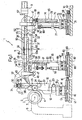
- Number 1 in Figure 1 indicates as a whole a system for forming a layer 4 of elastomeric material on a rubber-covering surface 2 of a toroidal body 3, e.g. a tyre carcass, by applying a shaped strip 5 of elastomeric material.
- System 1 comprises a unit 6 for supporting and rotating toroidal body 3 about a horizontal axis 7; an extruder 8 for producing a rope 9 of rubber; a forming unit 10 for receiving and drawing rope 9 into shaped strip 5, and for applying shaped strip 5 onto surface 2; and a feed unit 11 interposed between extruder 8 and forming unit 10 to feed rope 9 to an input of forming unit 10.
- Forming unit 10 is substantially known, and comprises a bed 12 having a horizontal guide 13 on top, crosswise to axis 7 and along which runs a carriage 14 powered by a motor 15 via a drive 16, e.g. a screw-nut screw drive.
- Carriage 14 in turn has a horizontal guide 17 on top, crosswise to guide 13 and normally parallel to axis 7, and along which runs a powered carriage 18 supporting a rotary fixture 19 rotated about a vertical axis 21 by a motor 20.
- a tubular frame 22 extends upwards from rotary fixture 19, rotates with rotary fixture 19 about axis 21, and houses an applicator roller 23, which is substantially tangent to axis 21, rotates on tubular frame 22 about a horizontal axis 24 crosswise to axis 21, and is moved into a position tangent to rubber-covering surface 2 by moving carriages 14 and 18.
- Applicator roller 23 receives shaped strip 5 from a powered roller calender 25 housed inside tubular frame 22, over applicator roller 23, to receive and shape rope 9 into shaped strip 5, and feed shaped strip 5 to applicator roller 23.
- Tubular frame 22 extends above roller calender 25 to support a female portion 26 of a releasable ball and socket joint 27, which comprises a male portion 28 extending downwards from an output end of a frame 29 of feed unit 11, and connected to frame 29 by a bearing 30, the axis 31 of which is substantially vertical and extends, in use, through the centre of ball and socket joint 27, and through the input of calender 25.
- Frame 29 is a telescopic frame, which has an axis 32 substantially crosswise to axis 7, and comprises a first portion - hereinafter referred to as “fixed portion” 33 - adjacent to the outlet of extruder 8; and a second portion - hereinafter referred to as “movable portion” 34 - which is mounted to slide on fixed portion 33, is fitted with male portion 28 of ball and socket joint 27, and is connectable to forming unit 10 by ball and socket joint 27.
- fixed portion 33 comprises a frame defined by a tubular body 35, through the end of which, facing forming unit 10, slides one end of a tubular beam 36 defining the frame of movable portion 34 and fitted, on its free end facing forming unit 10, with an L-shaped appendix 37, which extends beyond the relative end of tubular beam 36, is positioned, in use, over forming unit 10, and supports bearing 30 and male portion 28 of ball and socket joint 27.
- Frame 29 supports a conveyor 38 for receiving rope 9 from extruder 8 and conveying rope 9 to forming unit 10 in a direction 39 substantially parallel to axis 32.
- Conveyor 38 comprises a possibly powered input roller bed 40 supported by tubular body 35 and having a central gap, through which operates a known takeup roller unit 41 supported by tubular body 35, and a takeup roller 42 of which moves through roller bed 40 in a substantially vertical direction crosswise to axis 32.
- Conveyor 38 also comprises a possibly powered output roller bed 43 supported by tubular beam 36 and having an input portion 44 coplanar with roller bed 40, and a downward-sloping output portion 45 terminating, in use, over the input of roller calender 25.
- roller bed 43 has a gap, through which operates a known takeup roller unit 46 supported by tubular beam 36, and a takeup roller 47 of which moves through roller bed 43 in a substantially vertical direction crosswise to axis 32.
- Roller beds 40 and 43 are connected by a powered, variable-length, belt conveyor 48 comprising an endless belt 49 and defining a central portion of conveyor 38.
- Belt conveyor 48 comprises a conveying branch 50 - coplanar with roller bed 40 and with input portion 44 of roller bed 43 - and a return branch 51, which are defined by an input pulley 52 fitted in rotary manner to tubular body 35, and by an output pulley 53 fitted in rotary manner to tubular beam 36.
- Return branch 51 winds about a guide pulley 54 fitted in rotary manner to tubular body 35, and about two guide pulleys 55a and 55b.
- Pulley 55a is fitted in rotary manner to tubular body 35, and pulley 55b is interposed between pulleys 54 and 55a, is fitted in rotary manner to tubular beam 36, and defines, with pulley 55a and for belt 49, a known variable-capacity store 56 for compensating the variations in length of conveying branch 50 caused by movable portion 34 moving with respect to fixed portion 33.
- conveyor 38 comprises two cutting devices 57 and 58 for cutting rope 9. More specifically, cutting device 57 is fitted to tubular body 35, immediately upstream from roller bed 40, and cutting device 58 is fitted to tubular beam 36, at the output of roller bed 43.
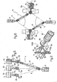
- Cutting devices 57 and 58 may be known straightforward guillotine devices, or, as shown in Figure 2 , at least one of cutting devices 57, 58, preferably at least cutting device 58, comprises two cutting cylinders 59 located on opposite sides of the path of rope 9, rotated in opposite directions about respective axes, and having respective blades 60, each of which extends radially outwards from an outer surface of relative cutting cylinder 59, and has a cutting edge 61 movable along a cylinder substantially tangent to the cylinder travelled by cutting edge 61 of the other blade 60.
- Cutting cylinders 59 are counter-rotated, in time with each other, by a motor 62, the output of which is connected to the input of a drive 63 comprising two identical meshing gears 64, each of which is coaxial and integral with relative cutting cylinder 59 to move relative cutting edge 61 in the same travelling direction as travelling direction 39 of rope 9 at a point at which cutting edge 61 is a minimum distance from the other cutting edge 61.
- Conveyor 38 has two supporting and adjusting devices, one of which is a supporting device 65 connected permanently to tubular body 35 and adjacent to extruder 8, and the other is a temporary supporting device 66 adjacent to forming unit 10.
- supporting device 65 comprises a bed 67 having a horizontal guide 68 on top, substantially crosswise to axis 7 and along which runs a carriage 69 powered by a motor 70 via a drive 71, e.g. a screw-nut screw drive.
- Carriage 69 in turn has a horizontal guide 72 on top, crosswise to guide 68, and along which runs a powered carriage 73 supporting a vertical guide 74, along which slides an upright 75 powered by a motor 76 via a drive 77, e.g. a screw-nut screw drive.
- Upright 75 is fitted on top with a thrust bearing 78 having a vertical axis 79 and connected to the bottom surface of tubular body 35 by a hinge 80 having a horizontal axis 81 substantially parallel to axis 7.
- supporting device 66 comprises a bed 82 having a horizontal guide 83 on top, parallel to guide 68 and along which runs a carriage 84 powered by a motor 85 via a drive 86, e.g. a screw-nut screw drive.
- Carriage 84 in turn has a horizontal guide 87 on top, crosswise to guide 83, and along which runs a powered carriage 88 supporting an upright 89, along which extends a vertical guide 90 for a carriage 91, which is connected to carriage 88 with the interposition of a hydraulic jack 92, and supports the vertical-axis male portion 93 of a releasable ball and socket joint 94, the female portion 95 of which is connected integrally to a bottom surface of tubular beam 36.
- feed unit 11 set beforehand so that it is shorter in length than the distance between extruder 8 and forming unit 10
- feed unit 11 is inserted, by operating carriages 73 and 88, between extruder 8 and forming unit 10 so that the input of roller bed 40 is aligned with the outlet of extruder 8, and appendix 37 is aligned with female portion 26 of ball and socket joint 27.
- carriage 91 is raised by means of jack 92, so that the whole of conveyor 38 rotates upwards about axis 81, and male portion 28 of ball and socket joint 27 is set to a height above relative female portion 26.
- conveyor 38 is lengthened to position male portion 28 directly over female portion 26; male portion 28 is inserted inside female portion 26 to engage ball and socket joint 27; and male portion 93 is withdrawn from female portion 95 to release ball and socket joint 94.
- Feed unit 11 is thus set in the operating position resting at one end on supporting device 65, and at the other end on forming unit 10, which, by operating carriage 14, is moved to position applicator roller 23 substantially contacting rubber-covering surface 2.
- conveyor 38 when forming layer 4, conveyor 38, as regards its length and its angular position about axis 79, is totally passive, and is lengthened, shortened, and rotated about axis 79 at all times by forming unit 10 by means of ball and socket joint 27.
- Figures 3 and 4 show respective systems 1a and 1b for covering rubber-covering surface 2 with a multilayer 4a comprising superimposed layers - in the example shown, two superimposed layers 4b and 4c - made of different mixes. This is done using a number of extruders 8, each for forming a respective rope 9 made of a respective mix; one forming unit 10; and one feed unit 11 connectable selectively to each of extruders 8 to feed ropes 9 selectively to forming unit 10.
- system 1a comprises two side by side extruders 8a and 8b located at the same height and for producing respective ropes 9a and 9b.
- feed unit 11 is connected selectively to extruders 8a and 8b by operation of carriage 73 rotating it about axis 31.
- extruders 8a and 8b are positioned radially with respect to, and at the same distance from, axis 31, and guide 72 is a circular guide coaxial with axis 31, then carriage 69 remains locked, and the length of conveyor 38 remains constant as carriage 73 is moved. If the extruders are different distances from axis 31, carriage 69 is also operated when rotating feed unit 11 about axis 31.
- each rope 9a, 9b is cut by cutting device 57.
- System 1b comprises two extruders 8c and 8d superimposed in the same plane through axis 31, and for producing respective ropes 9b and 9a.
- feed unit 11 is connected selectively to extruders 8c and 8d by operation of upright 75 rotating it about a horizontal axis 96, extending parallel to axis 81 and through the centre of ball and socket joint 27, and simultaneously about axis 81 itself. If extruders 8c and 8d are positioned radially with respect to, and at the same distance from, axis 96, then carriage 69 remains locked, and the length of conveyor 38 remains constant as upright 75 is moved. If extruders 8c and 8d are different distances from axis 96, carriage 69 is also operated when rotating feed unit 11.
- each rope 9a, 9b is cut by cutting device 57.
- Figures 5 and 6 show respective systems 1c and 1d, in which an extruder 8 and one feed unit 11 are employed to feed the relative rope 9 to a group of forming units 10 arranged parallel and each connected to a respective supporting unit 6.
- the parallel forming units 10 are three in number, are indicated 10a, 10b, 10c, and are connected to respective supporting units 6a, 6b, 6c, though a different number of parallel forming units 10 may obviously be employed.
- feed unit 11 is connected selectively to forming units 10a-10c by operation of carriage 88 rotating it about axis 79. More specifically, in actual use, feed unit 11 performs a succession of operating cycles, in each of which, feed unit 11 is first positioned between extruder 8 and forming unit 10a, as described relative to system1.
- feed unit 11 is first positioned between extruder 8 and forming unit 10a, as described relative to system1.
- rope 9 is cut by cutting device 58, and roller calender 25 of forming unit 10a is emptied to complete layer 4.
- jack 92 is operated to engage ball and socket joint 94, rotate frame 29 upwards about axis 81, release ball and socket joint 27 connecting feed unit 11 to forming unit 10a, and withdraw male portion 28 completely from female portion 26 of forming unit 10a.
- carriage 88 and possibly also carriage 84 are operated to rotate conveyor 38 about axis 79 and possibly adjust the length of frame 29 to position male portion 28 directly over female portion 26 of forming unit 10b.
- jack 92 is lowered to connect feed unit 11 to forming unit 10b as described relative to system 1.
Landscapes
- Engineering & Computer Science (AREA)
- Mechanical Engineering (AREA)
- Tyre Moulding (AREA)
- Extrusion Moulding Of Plastics Or The Like (AREA)
- Processing And Handling Of Plastics And Other Materials For Molding In General (AREA)
- Paper (AREA)
- Water Treatment By Sorption (AREA)
- Spinning Or Twisting Of Yarns (AREA)
- Materials For Medical Uses (AREA)
- Photographic Developing Apparatuses (AREA)
Abstract
Description
- The present invention relates to a system for forming a layer of elastomeric material on a user unit.
- In particular, the present invention relates to a systems, in which at least one extruder is used to feed extruded elastomeric material, normally in rope form, to at least one unit for applying the extruded elastomeric material to a user unit, specifically a toroidal body, such as a vehicle tyre carcass, having a rubber-covering surface and rotated about a respective axis, to form a cover layer on the rubber-covering surface, e.g. a layer constituting a component part of the tyre.
Patent specificationUS 3455764 - A discloses an apparatus for feeding a tire tread stock to a tire carcass.
Patent applicationDE 1556022 - A discloses a variable-length conveyor for transporting sheet-like materials.
Patent specificationUS 4240863 - A and international patent applicationWO 2005/009726 - A disclose conveying devices which are pivotable around one or more orthogonal axis. - It is an object of the present invention to provide a relatively straightforward, low-cost, multipurpose system of the type disclosed above to produce homogenous cover layers, i.e. made of one mix, or multilayer cover layers, i.e. formed by superimposing two or more homogeneous layers of respective different mixes.
- According to the present invention, there is provided a system for forming a layer of elastomeric material on a user unit, specifically on at least one toroidal body, as claimed in Claim 1 and preferably in any one of the Claims depending directly or indirectly on Claim 1.
- The invention will now be described by way of examples and with reference to the accompanying drawings, in which:
-
Figure 1 shows a schematic side view of a preferred embodiment of the system of the present invention; -
Figure 2 shows a larger-scale view in perspective of a preferred embodiment of a detail inFigure 1 ; -
Figures 3 to 6 show respective variations of theFigure 1 system. - Number 1 in
Figure 1 indicates as a whole a system for forming a layer 4 of elastomeric material on a rubber-coveringsurface 2 of atoroidal body 3, e.g. a tyre carcass, by applying ashaped strip 5 of elastomeric material. - System 1 comprises a
unit 6 for supporting and rotatingtoroidal body 3 about ahorizontal axis 7; anextruder 8 for producing arope 9 of rubber; a formingunit 10 for receiving and drawingrope 9 intoshaped strip 5, and for applyingshaped strip 5 ontosurface 2; and afeed unit 11 interposed betweenextruder 8 and formingunit 10 to feedrope 9 to an input of formingunit 10. - Forming
unit 10 is substantially known, and comprises abed 12 having ahorizontal guide 13 on top, crosswise toaxis 7 and along which runs acarriage 14 powered by amotor 15 via adrive 16, e.g. a screw-nut screw drive.Carriage 14 in turn has a horizontal guide 17 on top, crosswise to guide 13 and normally parallel toaxis 7, and along which runs a poweredcarriage 18 supporting arotary fixture 19 rotated about avertical axis 21 by amotor 20. Atubular frame 22 extends upwards fromrotary fixture 19, rotates withrotary fixture 19 aboutaxis 21, and houses anapplicator roller 23, which is substantially tangent toaxis 21, rotates ontubular frame 22 about ahorizontal axis 24 crosswise toaxis 21, and is moved into a position tangent to rubber-covering surface 2 by movingcarriages Applicator roller 23. receivesshaped strip 5 from a poweredroller calender 25 housed insidetubular frame 22, overapplicator roller 23, to receive andshape rope 9 intoshaped strip 5, and feed shapedstrip 5 toapplicator roller 23. -
Tubular frame 22 extends aboveroller calender 25 to support afemale portion 26 of a releasable ball andsocket joint 27, which comprises amale portion 28 extending downwards from an output end of aframe 29 offeed unit 11, and connected toframe 29 by abearing 30, theaxis 31 of which is substantially vertical and extends, in use, through the centre of ball andsocket joint 27, and through the input ofcalender 25. -
Frame 29 is a telescopic frame, which has anaxis 32 substantially crosswise toaxis 7, and comprises a first portion - hereinafter referred to as "fixed portion" 33 - adjacent to the outlet ofextruder 8; and a second portion - hereinafter referred to as "movable portion" 34 - which is mounted to slide on fixedportion 33, is fitted withmale portion 28 of ball andsocket joint 27, and is connectable to formingunit 10 by ball andsocket joint 27. - More specifically,
fixed portion 33 comprises a frame defined by a tubular body 35, through the end of which, facing formingunit 10, slides one end of atubular beam 36 defining the frame ofmovable portion 34 and fitted, on its free end facing formingunit 10, with an L-shaped appendix 37, which extends beyond the relative end oftubular beam 36, is positioned, in use, over formingunit 10, and supports bearing 30 andmale portion 28 of ball andsocket joint 27. -
Frame 29 supports aconveyor 38 for receivingrope 9 fromextruder 8 and conveyingrope 9 to formingunit 10 in adirection 39 substantially parallel toaxis 32.Conveyor 38 comprises a possibly poweredinput roller bed 40 supported by tubular body 35 and having a central gap, through which operates a knowntakeup roller unit 41 supported by tubular body 35, and atakeup roller 42 of which moves throughroller bed 40 in a substantially vertical direction crosswise toaxis 32.Conveyor 38 also comprises a possibly poweredoutput roller bed 43 supported bytubular beam 36 and having aninput portion 44 coplanar withroller bed 40, and a downward-slopingoutput portion 45 terminating, in use, over the input ofroller calender 25. Betweeninput portion 44 andoutput portion 45,roller bed 43 has a gap, through which operates a knowntakeup roller unit 46 supported bytubular beam 36, and atakeup roller 47 of which moves throughroller bed 43 in a substantially vertical direction crosswise toaxis 32.Roller beds belt conveyor 48 comprising anendless belt 49 and defining a central portion ofconveyor 38. -
Belt conveyor 48 comprises a conveying branch 50 - coplanar withroller bed 40 and withinput portion 44 of roller bed 43 - and a return branch 51, which are defined by aninput pulley 52 fitted in rotary manner to tubular body 35, and by anoutput pulley 53 fitted in rotary manner totubular beam 36. Return branch 51 winds about aguide pulley 54 fitted in rotary manner to tubular body 35, and about twoguide pulleys 55a and 55b. Pulley 55a is fitted in rotary manner to tubular body 35, andpulley 55b is interposed betweenpulleys 54 and 55a, is fitted in rotary manner totubular beam 36, and defines, with pulley 55a and forbelt 49, a known variable-capacity store 56 for compensating the variations in length of conveyingbranch 50 caused bymovable portion 34 moving with respect to fixedportion 33. - Finally,
conveyor 38 comprises twocutting devices cutting rope 9. More specifically,cutting device 57 is fitted to tubular body 35, immediately upstream fromroller bed 40, andcutting device 58 is fitted totubular beam 36, at the output ofroller bed 43. -
Cutting devices Figure 2 , at least one ofcutting devices cutting device 58, comprises twocutting cylinders 59 located on opposite sides of the path ofrope 9, rotated in opposite directions about respective axes, and havingrespective blades 60, each of which extends radially outwards from an outer surface ofrelative cutting cylinder 59, and has acutting edge 61 movable along a cylinder substantially tangent to the cylinder travelled bycutting edge 61 of theother blade 60.Cutting cylinders 59 are counter-rotated, in time with each other, by a motor 62, the output of which is connected to the input of adrive 63 comprising twoidentical meshing gears 64, each of which is coaxial and integral withrelative cutting cylinder 59 to moverelative cutting edge 61 in the same travelling direction as travellingdirection 39 ofrope 9 at a point at which cuttingedge 61 is a minimum distance from theother cutting edge 61. -
Conveyor 38 has two supporting and adjusting devices, one of which is a supportingdevice 65 connected permanently to tubular body 35 and adjacent toextruder 8, and the other is a temporary supportingdevice 66 adjacent to formingunit 10. - As shown in
Figure 1 , supportingdevice 65 comprises abed 67 having ahorizontal guide 68 on top, substantially crosswise toaxis 7 and along which runs acarriage 69 powered by amotor 70 via a drive 71, e.g. a screw-nut screw drive. Carriage 69 in turn has ahorizontal guide 72 on top, crosswise to guide 68, and along which runs a poweredcarriage 73 supporting avertical guide 74, along which slides an upright 75 powered by amotor 76 via a drive 77, e.g. a screw-nut screw drive. Upright 75 is fitted on top with a thrust bearing 78 having avertical axis 79 and connected to the bottom surface of tubular body 35 by ahinge 80 having ahorizontal axis 81 substantially parallel toaxis 7. - As shown in
Figure 1 , supportingdevice 66 comprises abed 82 having ahorizontal guide 83 on top, parallel to guide 68 and along which runs acarriage 84 powered by amotor 85 via adrive 86, e.g. a screw-nut screw drive. Carriage 84 in turn has ahorizontal guide 87 on top, crosswise to guide 83, and along which runs a poweredcarriage 88 supporting an upright 89, along which extends a vertical guide 90 for acarriage 91, which is connected tocarriage 88 with the interposition of ahydraulic jack 92, and supports the vertical-axismale portion 93 of a releasable ball andsocket joint 94, thefemale portion 95 of which is connected integrally to a bottom surface oftubular beam 36. - Setup of system 1 will now be described as of the instant in which
toroidal body 3 is fitted to supportingunit 6, formingunit 10 is positioned facing rubber-covering surface 2, with applicator roller 23 a given distance from rubber-covering surface 2, andextruder 8 is mounted facing and a given distance from formingunit 10, and at a given height, normally higher than the input ofroller calender 25, with respect to formingunit 10. - At this point,
feed unit 11, set beforehand so that it is shorter in length than the distance betweenextruder 8 and formingunit 10, is inserted, byoperating carriages extruder 8 and formingunit 10 so that the input ofroller bed 40 is aligned with the outlet ofextruder 8, andappendix 37 is aligned withfemale portion 26 of ball andsocket joint 27. - With supporting
device 66 locked, upright 75 andcarriage 69 are now operated to position the input ofroller bed 40 at a height just beneath the outlet ofextruder 8 and at a given distance from the outlet ofextruder 8 respectively. - Next, with supporting
device 65 locked,carriage 91 is raised by means ofjack 92, so that the whole ofconveyor 38 rotates upwards aboutaxis 81, andmale portion 28 of ball andsocket joint 27 is set to a height above relativefemale portion 26. Whencarriage 84 is operated, andcarriage 91 then lowered, the following occur in succession:conveyor 38 is lengthened to positionmale portion 28 directly overfemale portion 26;male portion 28 is inserted insidefemale portion 26 to engage ball andsocket joint 27; andmale portion 93 is withdrawn fromfemale portion 95 to release ball andsocket joint 94. -
Feed unit 11 is thus set in the operating position resting at one end on supportingdevice 65, and at the other end on formingunit 10, which, by operatingcarriage 14, is moved toposition applicator roller 23 substantially contacting rubber-coveringsurface 2. - Successive operation of
extruder 8 androller calender 25, operation ofbelt conveyor 48, programmed rotation (clockwise inFigure 1 ) oftoroidal body 3 aboutaxis 7, and programmed operation ofcarriages rotary fixture 19 of formingunit 10 result, successively and in known manner, in the formation ofrope 9, supply ofrope 9 toroller calender 25 to formshaped strip 5, application ofshaped strip 5 to rubber-covering surface 2, and the formation of layer 4. - In connection with the above, it should be pointed out that, if, as is often the case, supporting
unit 6 is movable in the direction ofaxis 7,carriage 18 may be left locked when forming layer 4. - It should also be pointed out that, when forming layer 4,
conveyor 38, as regards its length and its angular position aboutaxis 79, is totally passive, and is lengthened, shortened, and rotated aboutaxis 79 at all times by formingunit 10 by means of ball andsocket joint 27. - In system 1, connecting one
extruder 8 to one formingunit 10 to produce a homogenous layer 4, i.e. made from one mix,rope 9 is normally cut by cuttingdevice 57, once layer 4 is formed, andcutting device 58 may even be dispensed with. -
Figures 3 and 4 show respective systems 1a and 1b for covering rubber-coveringsurface 2 with amultilayer 4a comprising superimposed layers - in the example shown, twosuperimposed layers extruders 8, each for forming arespective rope 9 made of a respective mix; one formingunit 10; and onefeed unit 11 connectable selectively to each ofextruders 8 to feedropes 9 selectively to formingunit 10. - More specifically, system 1a comprises two side by
side extruders respective ropes feed unit 11 is connected selectively toextruders carriage 73 rotating it aboutaxis 31. - With reference to
Figure 1 , ifextruders axis 31, andguide 72 is a circular guide coaxial withaxis 31, thencarriage 69 remains locked, and the length ofconveyor 38 remains constant ascarriage 73 is moved. If the extruders are different distances fromaxis 31,carriage 69 is also operated when rotatingfeed unit 11 aboutaxis 31. - Once the
relative layer rope device 57. - System 1b comprises two
extruders axis 31, and for producingrespective ropes feed unit 11 is connected selectively toextruders horizontal axis 96, extending parallel toaxis 81 and through the centre of ball andsocket joint 27, and simultaneously aboutaxis 81 itself. Ifextruders axis 96, thencarriage 69 remains locked, and the length ofconveyor 38 remains constant as upright 75 is moved. Ifextruders axis 96,carriage 69 is also operated when rotatingfeed unit 11. - In this case, too, once the
relative layer rope device 57. - By combining systems 1a and 1b, it is possible to obtain a system (not shown), in which one forming
unit 10, served by onefeed unit 11, is connectable selectively to a number ofextruders 8 arranged in a given space (preferably in rows and columns) to form, on rubber-coveringsurface 2, amultilayer 4a defined by a number of superimposed layers, each made from a mix differing from those of the adjacent layers. -
Figures 5 and 6 showrespective systems extruder 8 and onefeed unit 11 are employed to feed therelative rope 9 to a group of formingunits 10 arranged parallel and each connected to a respective supportingunit 6. - In the
Figure 5 example, the parallel formingunits 10 are three in number, are indicated 10a, 10b, 10c, and are connected to respective supportingunits units 10 may obviously be employed. - In this case, feed
unit 11 is connected selectively to formingunits 10a-10c by operation ofcarriage 88 rotating it aboutaxis 79. More specifically, in actual use, feedunit 11 performs a succession of operating cycles, in each of which, feedunit 11 is first positioned betweenextruder 8 and formingunit 10a, as described relative to system1. When layer 4 is nearly completed on thetoroidal body 3 fitted to supportingunit 6a,rope 9 is cut by cuttingdevice 58, androller calender 25 of formingunit 10a is emptied to complete layer 4. At the same time,jack 92 is operated to engage ball and socket joint 94, rotateframe 29 upwards aboutaxis 81, release ball and socket joint 27 connectingfeed unit 11 to formingunit 10a, and withdrawmale portion 28 completely fromfemale portion 26 of formingunit 10a. Withframe 29 still in the raised position,carriage 88 and possibly alsocarriage 84 are operated to rotateconveyor 38 aboutaxis 79 and possibly adjust the length offrame 29 to positionmale portion 28 directly overfemale portion 26 of formingunit 10b. At which point,jack 92 is lowered to connectfeed unit 11 to formingunit 10b as described relative to system 1. - Once layer 4 is completed on the
toroidal body 3 fitted to supportingunit 6b,rope 9 is cut by cuttingdevice 58,roller calender 25 of formingunit 10b is emptied to complete layer 4, and feedunit 11 is disconnected from formingunit 10b and connected first to formingunit 10c, as described above, and then again to formingunit 10a. - In the
Figure 6 system 1d, twosystems 1c - sharing two formingunits respective ropes units toroidal bodies 3,respective multilayers 4a, each defined by twosuperimposed layers
Claims (15)
- A system for forming a layer (4; 4a; 4b; 4c) of elastomeric material (9) on at least one toroidal body (3), the system (1, 1a; 1b; 1c; 1d) comprising a supporting unit (6; 6a; 6b; 6c) for rotating the toroidal body (3) about a respective axis of rotation (7); at least one extruder (8; 8a, 8b; 8c, 8d) for producing a rope (9) of elastomeric material; at least one forming unit (10; 10a; 10b; 10c) connected to'the supporting unit (6; 6a; 6b; 6c) and for converting the rope (9) into a shaped strip (5) and applying the shaped strip (5) to the toroidal body (3) to form said layer (4; 4a; 4b; 4c); and at least one feed unit (11) for feeding the rope (9) from the extruder (8; 8a, 8b; 8c, 8d) to the forming unit (10; 10a; 10b; 10c); the system being characterized in that the feed unit (11) comprises a variable-length conveyor (38) comprising a variable-length frame (29); a first supporting device (65) connected to the frame (29) at an input end of the conveyor (38) to allow the conveyor (38) to rotate about a vertical first axis (79) and a horizontal second axis (81), both crosswise to a travelling direction (39) of the elastomeric material (9) along the conveyor (38); a first releasable joint (27) interposed between the frame (29) and the forming unit (10; 10a; 10b; 10c) at the output end of the conveyor (38), and a second supporting device (66) connectable releasably, by a normally-open second releasable joint (94), to the frame (29) at the output end of the conveyor (38).
- A system as claimed in Claim 1, wherein the first supporting device (65) comprises first extension means (76-77) for adjusting the height of the input end of the conveyor (38).
- A system as claimed in Claim 1 or 2, wherein the second supporting device (66) comprises second extension means (91, 92) for adjusting the height of the output end of the conveyor (38), and for engaging and releasing the second releasable joint (94).
- A system as claimed in anyone of the foregoing Claims, wherein the first and second releasable joint (27, 94) each comprise a male portion (28; 93) and a female portion (26; 95) detachable in a substantially vertical direction.
- A system as claimed in anyone of the foregoing Claims, wherein the first and second releasable joint (27, 94) are each a ball and socket joint.
- A system as claimed in anyone of the foregoing Claims, wherein said first and said second supporting device (65, 66) are each movable in a respective first and respective second horizontal direction perpendicular to each other.
- A system as claimed in anyone of the foregoing Claims, wherein the forming unit (10; 10a; 10b; 10c) comprises an applicator roller (23) having, in use, at least one point of substantial tangency with the toroidal body (3); and a rotary fixture (19) allowing the forming unit (10; 10a; 10b; 10c) to rotate about a vertical axis (21) passing substantially through the point of tangency; actuating means (18, 14) being provided to impart a first relative movement of the forming unit (10; 10a; 10b; 10c) with respect to the toroidal body (3) in a direction parallel to the axis of rotation (7) of the toroidal body (3), and a second relative movement of the forming unit (10; 10a; 10b; 10c) with respect to the toroidal body (3) in a direction crosswise to the axis of rotation (7) of the toroidal body (3).
- A system as claimed in anyone of the foregoing Claims, wherein the forming unit (10; 10a; 10b; 10c) has an input; and wherein the first releasable joint (27) permits rotation of the forming unit (10; 10a; 10b; 10c) and the feed unit (11) with respect to each other about a substantially vertical third axis (31) passing through said input, and about a substantially horizontal fourth axis (96).
- A system as claimed in anyone of the foregoing Claims, and comprising at least two extruders (8a, 8b; 8c, 8d); one forming unit (10) connected to the supporting unit (6) supporting the relative toroidal body (3); and one feed unit (11) connected, at the output, to the forming unit (10) by the first releasable joint (27), and connectable selectively, at the input, to the extruders (8a, 8b; 8c, 8d).
- A system as claimed in anyone of the foregoing Claims, wherein the two extruders (8a, 8b) are located at the same height; the feed unit (11) being selectively connectable to the extruders (8a, 8b) by at least rotating about the third axis (31).
- A system as claimed in Claims 8 and 9, wherein the two extruders (8c, 8d) are located at respective different heights; the feed unit (11) being selectively connectable to the extruders (8c, 8d) by at least rotating about the fourth axis (96).
- A system as claimed in anyone of Claims 9 to 11, and comprising a cutting device (57) for cutting the rope (9); the cutting device (57) being located at said input end.
- A system as claimed in anyone of Claims 1 to 8, and comprising one extruder (8); at least two forming units (10a, 10b), each connected to a respective supporting unit (6a; 6b) supporting the relative toroidal body (3); and one feed unit (11) connected, at the input, to the extruder (8), and connectable selectively, at the output, to the forming units (10a, 10b) by the respective first releasable joints (27) and by rotating about the first and second axis (79, 81).
- A system as claimed in Claim 13, and comprising a cutting device (58) for cutting the rope (9); the cutting device (58) being located at said output end.
- A system as claimed in one of Claims 1 to 8, and comprising a first and a second extruder (8); a first and a second forming unit (10a; 10b), each connected to a respective supporting unit (6a; 6b) supporting the relative toroidal body (3); and a first and a second feed unit (11) connected, at the input, to the first and second extruder (8) respectively, and connectable selectively, at the output, to the first and second forming unit (10a; 10b) by the respective first releasable joints (27) and by rotating about the respective first and second axis (79, 81).
Applications Claiming Priority (2)
| Application Number | Priority Date | Filing Date | Title |
|---|---|---|---|
| IT000065A ITTO20060065A1 (en) | 2006-02-01 | 2006-02-01 | SUPPLY UNIT OF ELASTOMERIC MATERIAL TO A USER UNIT. |
| PCT/IB2007/000223 WO2007088455A2 (en) | 2006-02-01 | 2007-01-31 | Feed unit for feeding elastomeric material to a user unit |
Publications (2)
| Publication Number | Publication Date |
|---|---|
| EP1989041A2 EP1989041A2 (en) | 2008-11-12 |
| EP1989041B1 true EP1989041B1 (en) | 2009-09-02 |
Family
ID=38255864
Family Applications (1)
| Application Number | Title | Priority Date | Filing Date |
|---|---|---|---|
| EP07705501A Not-in-force EP1989041B1 (en) | 2006-02-01 | 2007-01-31 | A system for forming a layer of elastomeric material on a user unit. |
Country Status (6)
| Country | Link |
|---|---|
| US (1) | US8012281B2 (en) |
| EP (1) | EP1989041B1 (en) |
| AT (1) | ATE441516T1 (en) |
| DE (1) | DE602007002281D1 (en) |
| IT (1) | ITTO20060065A1 (en) |
| WO (1) | WO2007088455A2 (en) |
Families Citing this family (12)
| Publication number | Priority date | Publication date | Assignee | Title |
|---|---|---|---|---|
| WO2009031435A1 (en) * | 2007-09-05 | 2009-03-12 | Bridgestone Corporation | Method and apparatus for manufacturing unvulcanized tire |
| DE102007049870A1 (en) * | 2007-10-18 | 2009-04-23 | Continental Aktiengesellschaft | Device for applying strips of material to a green tire or a building drum |
| DE102007056220B4 (en) | 2007-11-22 | 2021-10-07 | Continental Reifen Deutschland Gmbh | Method for producing tire components from strips of material |
| DE102008016569A1 (en) * | 2008-04-01 | 2009-10-08 | Continental Aktiengesellschaft | Method and device for transporting an extruded round cord of a rubber mixture to a calendering device |
| KR101426429B1 (en) | 2008-04-23 | 2014-08-06 | 피렐리 타이어 소시에떼 퍼 아찌오니 | Process and Apparatus for Building Tyres |
| FR2975040B1 (en) * | 2011-05-10 | 2013-06-28 | Michelin Soc Tech | TOOL FOR INSTALLING A BANDLET FOR REALIZING A PNEUMATIC BRAKE |
| CN103182789A (en) * | 2011-12-31 | 2013-07-03 | 软控股份有限公司 | Belt ply feeding rack and feeding method thereof |
| EP2905123B1 (en) * | 2012-10-02 | 2018-02-28 | Sumitomo Rubber Industries, Ltd. | Tire manufacturing system |
| US20150041067A1 (en) * | 2013-08-07 | 2015-02-12 | The Goodyear Tire & Rubber Company | Component applying/cutting apparatus for a tire building machine |
| DE102014015490A1 (en) * | 2014-10-14 | 2016-04-14 | Harburg-Freudenberger Maschinenbau Gmbh | Apparatus and process for the production of green tires |
| JP6723518B2 (en) * | 2016-07-22 | 2020-07-15 | 住友ゴム工業株式会社 | Rubber rubber molding equipment |
| WO2018089307A2 (en) * | 2016-11-10 | 2018-05-17 | Bridgestone Americas Tire Operations, Llc | Tire with variable ribbon size tread and system and method for making same |
Family Cites Families (11)
| Publication number | Priority date | Publication date | Assignee | Title |
|---|---|---|---|---|
| US3455764A (en) * | 1966-04-21 | 1969-07-15 | Nat Standard Co | Tire treading apparatus |
| DE1556022A1 (en) * | 1967-10-11 | 1970-01-15 | Th Jaeger Feinpappenfabrik | Endose conveyor belt |
| US3904024A (en) * | 1974-01-21 | 1975-09-09 | Huss Equipment Corp | Apparatus for transferring objects |
| US4279555A (en) * | 1978-12-29 | 1981-07-21 | Rydell Edmund W F | Machine for stacking panels |
| US4240863A (en) * | 1979-04-12 | 1980-12-23 | Caterpillar Tractor Co. | Control system for an elastomer extrusion and applicator apparatus |
| DE3616485A1 (en) * | 1986-05-20 | 1987-11-26 | Orenstein & Koppel Ag | DISTRIBUTOR WITH CONNECTOR |
| DE4111740A1 (en) * | 1991-04-06 | 1992-10-08 | Knaup Maschfgmbh & Co | Loader for piece goods, with three conveyor belts - has trolley with two-part projecting arm, and one belt, pivoted through 180 deg. |
| CA2128453A1 (en) * | 1993-07-22 | 1995-01-23 | Garth B. Maughan | Ball and socket joint assembly |
| JP3322648B2 (en) * | 1999-03-03 | 2002-09-09 | 住友ゴム工業株式会社 | Rubber conveying device and rubber molding device using the same |
| JP4375866B2 (en) * | 2000-01-25 | 2009-12-02 | 横浜ゴム株式会社 | Method and device for winding rubber strip material |
| NL1024009C2 (en) | 2003-07-28 | 2005-02-07 | Vmi Epe Holland | Tread application device. |
-
2006
- 2006-02-01 IT IT000065A patent/ITTO20060065A1/en unknown
-
2007
- 2007-01-31 WO PCT/IB2007/000223 patent/WO2007088455A2/en not_active Ceased
- 2007-01-31 US US12/162,884 patent/US8012281B2/en not_active Expired - Fee Related
- 2007-01-31 EP EP07705501A patent/EP1989041B1/en not_active Not-in-force
- 2007-01-31 DE DE602007002281T patent/DE602007002281D1/en active Active
- 2007-01-31 AT AT07705501T patent/ATE441516T1/en not_active IP Right Cessation
Also Published As
| Publication number | Publication date |
|---|---|
| EP1989041A2 (en) | 2008-11-12 |
| DE602007002281D1 (en) | 2009-10-15 |
| ATE441516T1 (en) | 2009-09-15 |
| WO2007088455A3 (en) | 2007-10-18 |
| WO2007088455A8 (en) | 2008-08-21 |
| US20090223637A1 (en) | 2009-09-10 |
| WO2007088455A2 (en) | 2007-08-09 |
| ITTO20060065A1 (en) | 2007-08-02 |
| US8012281B2 (en) | 2011-09-06 |
Similar Documents
| Publication | Publication Date | Title |
|---|---|---|
| US8012281B2 (en) | Feed unit for feeding elastomeric material to a user unit | |
| US8622199B2 (en) | Adjustable conveyor extensions | |
| CN103009651B (en) | High-efficiency three-drum forming machine | |
| EP2598322B1 (en) | Method and device for manufacturing green tyres | |
| US8800629B2 (en) | Tire ply applier | |
| CN104960316A (en) | Novel composite colorful steel plate streamline | |
| EP4194190B1 (en) | Tire production device and tire production method | |
| CN103862691A (en) | Method and apparatus for building a tire | |
| CN112590357B (en) | Automatic stacking and feeding device for composite material production | |
| JP2010506766A (en) | Assembly for manufacturing tire component and method for manufacturing tire component | |
| JP2026016537A (en) | Systems and methods for manufacturing composite components | |
| KR102501574B1 (en) | Belt forming system and method for manufacturing at least a portion of a tire belt | |
| CN1974194A (en) | Split cord geodesic configurations for a tire | |
| SU1736333A3 (en) | Plant for manufacture of triplex | |
| EP2116362B1 (en) | 3-dimensional strip winding system for special giant all-steel radial OTR tire | |
| CN214395536U (en) | Cord splice device | |
| US9114581B2 (en) | Method of applying ply to a tire building drum | |
| EP1993817B1 (en) | Variable-centreline tyre building drum | |
| CN112848433A (en) | Cord fabric connector device | |
| CN217455003U (en) | Forming machine | |
| EP2607064B1 (en) | Method and apparatus for applying a sheet of flexible material to a cylindrical body | |
| CN224013023U (en) | Drum type laminating machine | |
| JP5681222B2 (en) | Cylindrical member manufacturing apparatus and manufacturing method | |
| CN1974195A (en) | Cord tensioning and feed mechanism for a tire cord applicator head | |
| CN110900695A (en) | An automatic rotating table of a sponge cutting machine |
Legal Events
| Date | Code | Title | Description |
|---|---|---|---|
| PUAI | Public reference made under article 153(3) epc to a published international application that has entered the european phase |
Free format text: ORIGINAL CODE: 0009012 |
|
| 17P | Request for examination filed |
Effective date: 20080830 |
|
| AK | Designated contracting states |
Kind code of ref document: A2 Designated state(s): AT BE BG CH CY CZ DE DK EE ES FI FR GB GR HU IE IS IT LI LT LU LV MC NL PL PT RO SE SI SK TR |
|
| GRAP | Despatch of communication of intention to grant a patent |
Free format text: ORIGINAL CODE: EPIDOSNIGR1 |
|
| GRAC | Information related to communication of intention to grant a patent modified |
Free format text: ORIGINAL CODE: EPIDOSCIGR1 |
|
| RTI1 | Title (correction) |
Free format text: A SYSTEM FOR FORMING A LAYER OF ELASTOMERIC MATERIAL ON A USER UNIT. |
|
| GRAS | Grant fee paid |
Free format text: ORIGINAL CODE: EPIDOSNIGR3 |
|
| GRAA | (expected) grant |
Free format text: ORIGINAL CODE: 0009210 |
|
| AK | Designated contracting states |
Kind code of ref document: B1 Designated state(s): AT BE BG CH CY CZ DE DK EE ES FI FR GB GR HU IE IS IT LI LT LU LV MC NL PL PT RO SE SI SK TR |
|
| REG | Reference to a national code |
Ref country code: CH Ref legal event code: EP |
|
| REG | Reference to a national code |
Ref country code: IE Ref legal event code: FG4D |
|
| REF | Corresponds to: |
Ref document number: 602007002281 Country of ref document: DE Date of ref document: 20091015 Kind code of ref document: P |
|
| PG25 | Lapsed in a contracting state [announced via postgrant information from national office to epo] |
Ref country code: LT Free format text: LAPSE BECAUSE OF FAILURE TO SUBMIT A TRANSLATION OF THE DESCRIPTION OR TO PAY THE FEE WITHIN THE PRESCRIBED TIME-LIMIT Effective date: 20090902 Ref country code: SE Free format text: LAPSE BECAUSE OF FAILURE TO SUBMIT A TRANSLATION OF THE DESCRIPTION OR TO PAY THE FEE WITHIN THE PRESCRIBED TIME-LIMIT Effective date: 20090902 Ref country code: FI Free format text: LAPSE BECAUSE OF FAILURE TO SUBMIT A TRANSLATION OF THE DESCRIPTION OR TO PAY THE FEE WITHIN THE PRESCRIBED TIME-LIMIT Effective date: 20090902 |
|
| LTIE | Lt: invalidation of european patent or patent extension |
Effective date: 20090902 |
|
| PG25 | Lapsed in a contracting state [announced via postgrant information from national office to epo] |
Ref country code: LV Free format text: LAPSE BECAUSE OF FAILURE TO SUBMIT A TRANSLATION OF THE DESCRIPTION OR TO PAY THE FEE WITHIN THE PRESCRIBED TIME-LIMIT Effective date: 20090902 Ref country code: SI Free format text: LAPSE BECAUSE OF FAILURE TO SUBMIT A TRANSLATION OF THE DESCRIPTION OR TO PAY THE FEE WITHIN THE PRESCRIBED TIME-LIMIT Effective date: 20090902 Ref country code: PL Free format text: LAPSE BECAUSE OF FAILURE TO SUBMIT A TRANSLATION OF THE DESCRIPTION OR TO PAY THE FEE WITHIN THE PRESCRIBED TIME-LIMIT Effective date: 20090902 |
|
| REG | Reference to a national code |
Ref country code: SK Ref legal event code: T3 Ref document number: E 6396 Country of ref document: SK |
|
| PG25 | Lapsed in a contracting state [announced via postgrant information from national office to epo] |
Ref country code: CY Free format text: LAPSE BECAUSE OF FAILURE TO SUBMIT A TRANSLATION OF THE DESCRIPTION OR TO PAY THE FEE WITHIN THE PRESCRIBED TIME-LIMIT Effective date: 20090902 |
|
| PG25 | Lapsed in a contracting state [announced via postgrant information from national office to epo] |
Ref country code: ES Free format text: LAPSE BECAUSE OF FAILURE TO SUBMIT A TRANSLATION OF THE DESCRIPTION OR TO PAY THE FEE WITHIN THE PRESCRIBED TIME-LIMIT Effective date: 20091213 Ref country code: RO Free format text: LAPSE BECAUSE OF FAILURE TO SUBMIT A TRANSLATION OF THE DESCRIPTION OR TO PAY THE FEE WITHIN THE PRESCRIBED TIME-LIMIT Effective date: 20090902 Ref country code: PT Free format text: LAPSE BECAUSE OF FAILURE TO SUBMIT A TRANSLATION OF THE DESCRIPTION OR TO PAY THE FEE WITHIN THE PRESCRIBED TIME-LIMIT Effective date: 20100104 Ref country code: EE Free format text: LAPSE BECAUSE OF FAILURE TO SUBMIT A TRANSLATION OF THE DESCRIPTION OR TO PAY THE FEE WITHIN THE PRESCRIBED TIME-LIMIT Effective date: 20090902 Ref country code: IS Free format text: LAPSE BECAUSE OF FAILURE TO SUBMIT A TRANSLATION OF THE DESCRIPTION OR TO PAY THE FEE WITHIN THE PRESCRIBED TIME-LIMIT Effective date: 20100102 |
|
| PG25 | Lapsed in a contracting state [announced via postgrant information from national office to epo] |
Ref country code: BE Free format text: LAPSE BECAUSE OF FAILURE TO SUBMIT A TRANSLATION OF THE DESCRIPTION OR TO PAY THE FEE WITHIN THE PRESCRIBED TIME-LIMIT Effective date: 20090902 Ref country code: AT Free format text: LAPSE BECAUSE OF FAILURE TO SUBMIT A TRANSLATION OF THE DESCRIPTION OR TO PAY THE FEE WITHIN THE PRESCRIBED TIME-LIMIT Effective date: 20090902 |
|
| PLBE | No opposition filed within time limit |
Free format text: ORIGINAL CODE: 0009261 |
|
| STAA | Information on the status of an ep patent application or granted ep patent |
Free format text: STATUS: NO OPPOSITION FILED WITHIN TIME LIMIT |
|
| PG25 | Lapsed in a contracting state [announced via postgrant information from national office to epo] |
Ref country code: DK Free format text: LAPSE BECAUSE OF FAILURE TO SUBMIT A TRANSLATION OF THE DESCRIPTION OR TO PAY THE FEE WITHIN THE PRESCRIBED TIME-LIMIT Effective date: 20090902 |
|
| 26N | No opposition filed |
Effective date: 20100603 |
|
| PG25 | Lapsed in a contracting state [announced via postgrant information from national office to epo] |
Ref country code: MC Free format text: LAPSE BECAUSE OF NON-PAYMENT OF DUE FEES Effective date: 20100131 |
|
| PG25 | Lapsed in a contracting state [announced via postgrant information from national office to epo] |
Ref country code: GR Free format text: LAPSE BECAUSE OF FAILURE TO SUBMIT A TRANSLATION OF THE DESCRIPTION OR TO PAY THE FEE WITHIN THE PRESCRIBED TIME-LIMIT Effective date: 20091203 |
|
| PG25 | Lapsed in a contracting state [announced via postgrant information from national office to epo] |
Ref country code: IE Free format text: LAPSE BECAUSE OF NON-PAYMENT OF DUE FEES Effective date: 20100131 |
|
| PGRI | Patent reinstated in contracting state [announced from national office to epo] |
Ref country code: IT Effective date: 20110501 |
|
| PGRI | Patent reinstated in contracting state [announced from national office to epo] |
Ref country code: IT Effective date: 20110501 |
|
| REG | Reference to a national code |
Ref country code: CH Ref legal event code: PL |
|
| GBPC | Gb: european patent ceased through non-payment of renewal fee |
Effective date: 20110131 |
|
| PG25 | Lapsed in a contracting state [announced via postgrant information from national office to epo] |
Ref country code: LI Free format text: LAPSE BECAUSE OF NON-PAYMENT OF DUE FEES Effective date: 20110131 Ref country code: CH Free format text: LAPSE BECAUSE OF NON-PAYMENT OF DUE FEES Effective date: 20110131 |
|
| PG25 | Lapsed in a contracting state [announced via postgrant information from national office to epo] |
Ref country code: GB Free format text: LAPSE BECAUSE OF NON-PAYMENT OF DUE FEES Effective date: 20110131 |
|
| PG25 | Lapsed in a contracting state [announced via postgrant information from national office to epo] |
Ref country code: LU Free format text: LAPSE BECAUSE OF NON-PAYMENT OF DUE FEES Effective date: 20100131 Ref country code: HU Free format text: LAPSE BECAUSE OF FAILURE TO SUBMIT A TRANSLATION OF THE DESCRIPTION OR TO PAY THE FEE WITHIN THE PRESCRIBED TIME-LIMIT Effective date: 20100303 Ref country code: BG Free format text: LAPSE BECAUSE OF FAILURE TO SUBMIT A TRANSLATION OF THE DESCRIPTION OR TO PAY THE FEE WITHIN THE PRESCRIBED TIME-LIMIT Effective date: 20090902 |
|
| PG25 | Lapsed in a contracting state [announced via postgrant information from national office to epo] |
Ref country code: TR Free format text: LAPSE BECAUSE OF FAILURE TO SUBMIT A TRANSLATION OF THE DESCRIPTION OR TO PAY THE FEE WITHIN THE PRESCRIBED TIME-LIMIT Effective date: 20090902 |
|
| PGFP | Annual fee paid to national office [announced via postgrant information from national office to epo] |
Ref country code: NL Payment date: 20140110 Year of fee payment: 8 Ref country code: SK Payment date: 20140109 Year of fee payment: 8 Ref country code: DE Payment date: 20140129 Year of fee payment: 8 Ref country code: CZ Payment date: 20140114 Year of fee payment: 8 |
|
| PGFP | Annual fee paid to national office [announced via postgrant information from national office to epo] |
Ref country code: FR Payment date: 20140108 Year of fee payment: 8 Ref country code: IT Payment date: 20140123 Year of fee payment: 8 |
|
| REG | Reference to a national code |
Ref country code: DE Ref legal event code: R119 Ref document number: 602007002281 Country of ref document: DE |
|
| REG | Reference to a national code |
Ref country code: NL Ref legal event code: V1 Effective date: 20150801 |
|
| PG25 | Lapsed in a contracting state [announced via postgrant information from national office to epo] |
Ref country code: NL Free format text: LAPSE BECAUSE OF NON-PAYMENT OF DUE FEES Effective date: 20150801 |
|
| REG | Reference to a national code |
Ref country code: SK Ref legal event code: MM4A Ref document number: E 6396 Country of ref document: SK Effective date: 20150131 |
|
| PG25 | Lapsed in a contracting state [announced via postgrant information from national office to epo] |
Ref country code: DE Free format text: LAPSE BECAUSE OF NON-PAYMENT OF DUE FEES Effective date: 20150801 Ref country code: SK Free format text: LAPSE BECAUSE OF NON-PAYMENT OF DUE FEES Effective date: 20150131 Ref country code: CZ Free format text: LAPSE BECAUSE OF NON-PAYMENT OF DUE FEES Effective date: 20150131 |
|
| REG | Reference to a national code |
Ref country code: FR Ref legal event code: ST Effective date: 20150930 |
|
| PG25 | Lapsed in a contracting state [announced via postgrant information from national office to epo] |
Ref country code: FR Free format text: LAPSE BECAUSE OF NON-PAYMENT OF DUE FEES Effective date: 20150202 |
|
| PG25 | Lapsed in a contracting state [announced via postgrant information from national office to epo] |
Ref country code: IT Free format text: LAPSE BECAUSE OF NON-PAYMENT OF DUE FEES Effective date: 20150131 |