EP1989023B1 - Dreiwege-ratschenantriebsmechanismus - Google Patents
Dreiwege-ratschenantriebsmechanismus Download PDFInfo
- Publication number
- EP1989023B1 EP1989023B1 EP07701810.9A EP07701810A EP1989023B1 EP 1989023 B1 EP1989023 B1 EP 1989023B1 EP 07701810 A EP07701810 A EP 07701810A EP 1989023 B1 EP1989023 B1 EP 1989023B1
- Authority
- EP
- European Patent Office
- Prior art keywords
- housing
- spring
- sleeve
- ratchet
- drive mechanism
- Prior art date
- Legal status (The legal status is an assumption and is not a legal conclusion. Google has not performed a legal analysis and makes no representation as to the accuracy of the status listed.)
- Active
Links
- 230000007246 mechanism Effects 0.000 title claims description 40
- 230000006835 compression Effects 0.000 claims description 5
- 238000007906 compression Methods 0.000 claims description 5
- 230000000717 retained effect Effects 0.000 claims description 4
- 229910000831 Steel Inorganic materials 0.000 description 8
- 239000010959 steel Substances 0.000 description 8
- 239000000463 material Substances 0.000 description 4
- 230000009977 dual effect Effects 0.000 description 2
- XAGFODPZIPBFFR-UHFFFAOYSA-N aluminium Chemical compound [Al] XAGFODPZIPBFFR-UHFFFAOYSA-N 0.000 description 1
- 229910052782 aluminium Inorganic materials 0.000 description 1
- 230000001010 compromised effect Effects 0.000 description 1
- 230000007774 longterm Effects 0.000 description 1
- 239000000203 mixture Substances 0.000 description 1
- 238000012986 modification Methods 0.000 description 1
- 230000004048 modification Effects 0.000 description 1
Images


Classifications
-
- B—PERFORMING OPERATIONS; TRANSPORTING
- B25—HAND TOOLS; PORTABLE POWER-DRIVEN TOOLS; MANIPULATORS
- B25B—TOOLS OR BENCH DEVICES NOT OTHERWISE PROVIDED FOR, FOR FASTENING, CONNECTING, DISENGAGING OR HOLDING
- B25B15/00—Screwdrivers
- B25B15/02—Screwdrivers operated by rotating the handle
- B25B15/04—Screwdrivers operated by rotating the handle with ratchet action
-
- B—PERFORMING OPERATIONS; TRANSPORTING
- B25—HAND TOOLS; PORTABLE POWER-DRIVEN TOOLS; MANIPULATORS
- B25B—TOOLS OR BENCH DEVICES NOT OTHERWISE PROVIDED FOR, FOR FASTENING, CONNECTING, DISENGAGING OR HOLDING
- B25B13/00—Spanners; Wrenches
- B25B13/46—Spanners; Wrenches of the ratchet type, for providing a free return stroke of the handle
- B25B13/461—Spanners; Wrenches of the ratchet type, for providing a free return stroke of the handle with concentric driving and driven member
- B25B13/462—Spanners; Wrenches of the ratchet type, for providing a free return stroke of the handle with concentric driving and driven member the ratchet parts engaging in a direction radial to the tool operating axis
- B25B13/463—Spanners; Wrenches of the ratchet type, for providing a free return stroke of the handle with concentric driving and driven member the ratchet parts engaging in a direction radial to the tool operating axis a pawl engaging an externally toothed wheel
-
- B—PERFORMING OPERATIONS; TRANSPORTING
- B25—HAND TOOLS; PORTABLE POWER-DRIVEN TOOLS; MANIPULATORS
- B25B—TOOLS OR BENCH DEVICES NOT OTHERWISE PROVIDED FOR, FOR FASTENING, CONNECTING, DISENGAGING OR HOLDING
- B25B13/00—Spanners; Wrenches
- B25B13/46—Spanners; Wrenches of the ratchet type, for providing a free return stroke of the handle
- B25B13/461—Spanners; Wrenches of the ratchet type, for providing a free return stroke of the handle with concentric driving and driven member
- B25B13/468—Spanners; Wrenches of the ratchet type, for providing a free return stroke of the handle with concentric driving and driven member with possibility of locking the ratchet mechanism
-
- F—MECHANICAL ENGINEERING; LIGHTING; HEATING; WEAPONS; BLASTING
- F16—ENGINEERING ELEMENTS AND UNITS; GENERAL MEASURES FOR PRODUCING AND MAINTAINING EFFECTIVE FUNCTIONING OF MACHINES OR INSTALLATIONS; THERMAL INSULATION IN GENERAL
- F16D—COUPLINGS FOR TRANSMITTING ROTATION; CLUTCHES; BRAKES
- F16D41/00—Freewheels or freewheel clutches
- F16D41/12—Freewheels or freewheel clutches with hinged pawl co-operating with teeth, cogs, or the like
- F16D41/16—Freewheels or freewheel clutches with hinged pawl co-operating with teeth, cogs, or the like the action being reversible
Definitions
- the present invention relates to a ratchet drive mechanism for a screwdriver bit or other work tool.
- ratchet tools There are a wide variety of known designs for ratchet tools. Typically, such tools have two modes of operation, either one of which may be selectively set by the user. In the first mode (for example to tighten a screw) ratcheting operation is enabled in a clockwise direction. In the second mode (for example to loosen a screw) ratcheting operation is enabled in an anti-clockwise direction.
- first mode for example to tighten a screw
- second mode for example to loosen a screw
- ratcheting operation is enabled in an anti-clockwise direction.
- the present invention provides a three-way ratchet drive mechanism which not only may be set, selectively, to enable ratcheting operation in a clockwise direction, or to enable ratcheting operation in an anti-clockwise direction, but also to enable non-ratcheting operation where ratcheting behaviour is locked out and disabled and the drive mechanism engages whether the tool is turned clockwise or anti-clockwise.
- a three-way ratchet drive mechanism for a work tool which mechanism is settable, selectively, to a desired one of three modes of operation, namely, a first mode of operation where ratcheting operation is enabled in a clockwise direction, a second mode of operation where ratcheting operation is enabled in an anti-clockwise direction, or a third mode of operation where the drive mechanism is locked and ratcheting operation is disabled, said mechanism comprising:
- the overall length of the sleeve and housing may be made very compact.
- the first and seconds tabs of the selector sleeve provide for a positive, reliable control which acts directly on the pawls against the bias of the pawl spring.
- the foregoing ratchet drive mechanism includes a bearing sleeve axially aligned with and longitudinally spaced from the guide tube.
- the bearing sleeve is sized for providing lateral bearing support to the second end portion of the drive shaft.
- the bearing sleeve is fitted to the housing and, for compactness, is fitted to the housing within the selector sleeve.
- the foregoing ratchet drive mechanism may include a shaft bearing abutting the proximal end of the drive shaft.
- the drive shaft may have a radially stepped cylindrical configuration, the first end portion of the shaft having a diameter less than the diameter of the second end portion of the shaft.
- the smaller diameter of the first end portion allows for more room within the housing for the positioning of the ratchet wheel and other elements.
- the selector sleeve retaining means comprises:
- the pawl spring performs not only the function of biasing the pawls but also the function of the selector ball and selector spring in the immediate previously described embodiment.
- the lower part of a drive mechanism in accordance with the present invention may include differently sized splines adapted to engage a screwdriver handle when press fitted to the mechanism. As discussed below, this is a commercially practical feature which better enables the proper alignment of any desired trade marks or other identifying indicia.
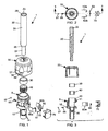
- Drive mechanism 1 includes a die cast aluminum ratchet housing generally designated 5, a generally cylindrical steel drive shaft 20 extending from a relatively small diameter proximal end 21 of end portion 22 of the shaft to a relatively large diameter distal end 29 of end portion 28 of the shaft, an annular plastic bearing sleeve 30 fitted to the housing, a steel spline or ratchet wheel 40 which is coaxially press fitted on end portion 22 of shaft 20, a resilient plastic selector sleeve generally designated 50, a pair of J-shaped steel ratchet pawls 60a, 60b which are of substantially the same size, and a plastic retaining clip 70.
- a die cast aluminum ratchet housing generally designated 5
- a generally cylindrical steel drive shaft 20 extending from a relatively small diameter proximal end 21 of end portion 22 of the shaft to a relatively large diameter distal end 29 of end portion 28 of the shaft
- an annular plastic bearing sleeve 30 fitted to the housing
- drive mechanism 1 includes an inner steel coil spring 90, a steel selector spring 95, a steel selector ball 97, and a steel shaft bearing 98, the latter of which is a seated in a recess 7 formed in housing 5 at the bottom of guide tube 8 also formed in housing 5.
- Guide tube 8 and bearing sleeve 30 are in axial alignment.
- Shaft bearing 98 abuts proximal end 21 of shaft 20 on the longitudinal axis of the shaft. While not considered essential, it advantageously enables easier rotation of the shaft when compression forces are acting on the shaft.
- Shaft 20 includes a socket 23 which is sized to receive and magnetically hold a conventional screwdriver bit or other work tool (not shown). Between end portions 22, 28, shaft 20 includes a stepped cylindrical portion 25 against which ratchet wheel 40 abuts.
- shaft 20 is supported not only longitudinally by shaft bearing 98 but also laterally at longitudinally spaced locations by bearing sleeve 30 and guide tube 8.
- the inner cylindrical wall of guide tube 8 is sized for providing lateral bearing support to the first end portion 22 of shaft 20.
- the inner cylindrical wall 35 of bearing sleeve 30 is sized for providing lateral bearing support to the second end portion of shaft 20. Such lateral support enables shaft 20 to better resist side forces and impacts on the shaft or on a work tool carried by the shaft.
- Housing 5 is configured and selector sleeve 50 is cooperatively configured to enable the sleeve to be coaxially snap-fitted over the housing. More particularly, housing 5 includes a downwardly and outwardly tapered portion 10 which merges with a radially inwardly extending annular channel 11. Radially inwardly extending tabs 51 of selector sleeve 50 engage housing 5 in channel 11, the engagement being enabled because selector sleeve 50 resiliently flexes outwardly as tabs 51 ride down on tapered portion 10 toward channel 11. The engagement is sufficiently loose to permit easy rotation of the selector sleeve relative to the housing.
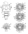
- housing 5 The lower part of housing 5 includes wings or splines 12, 13 and barbs 14 to engage a screwdriver handle (not shown) when press fitted onto the housing.
- splines 12 and 13 are of differing dimensions.
- Spline 12 is shorter than spline 13.
- spline12 is narrower than spline 13.
- the indicia which appears on selector sleeve 50 at least includes directional markings.
- these markings include a marking 57 which designates the direction of movement of sleeve 50 for setting clockwise ratcheting operation (viz. a first mode of operation), a marking 59 which designates the direction of movement of sleeve 50 for setting anti-clockwise ratcheting operation (viz. a second mode operation), and a marking 58 which designates the position of sleeve 50 to enable non-ratcheting operation (viz. a third mode of operation) where ratcheting behaviour is disabled.
- selector spring 95 is a compression spring seated in a cylindrical recess 15 in housing 5 and serves to urge selector ball 97 into a selected one of three recesses 54, 55, 56 in the lower inner wall of selector sleeve 50 (see also FIGS. 12 and 13 ).
- ball 97 is urged into recess 55 where non-ratcheting operation is enabled. If selector sleeve 50 is rotated anti-clockwise from the position shown in FIG. 9 , then ball 97 will be urged into recess 56 where clockwise ratcheting operation is enabled. Conversely, if selector sleeve 50 is rotated clockwise from the position shown FIG. 9 , then ball 97 will be urged into recess 54 where anti-clockwise ratcheting operation is enabled.
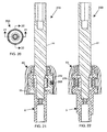
- retaining clip 70 holds coil spring 90 (best seen in FIGS. 15-16 ) in a position where its arms 91, 92 bear against pawls 60a, 60b thereby urging the pawls substantially linearly towards ratchet wheel 40.
- selector sleeve 50 is centrally positioned for non-ratcheting operation then, as shown in FIG. 8 , pawl 60a is urged into abutment with tooth 41a of ratchet wheel 40 and pawl 60b is urged into abutment with tooth 41 b of the ratchet wheel. This effectively disables ratcheting operation because ratchet wheel 40 cannot advance either clockwise or anti-clockwise.
- coil spring 90 can also be performed by other means.
- a leaf spring 190 with left and right arms 191, 192 as shown in FIGS. 17 - 18 may be substituted for coil spring 90 with left and right arms 91, 92.
- the means used to perform the function of coil spring 90 in the first embodiment advantageously can also be used to perform the function of selector spring 95 and selector ball 97 in the first embodiment.
- the result is fewer parts since the need for the selector spring and selector ball is avoided.
- ratchet drive mechanism 200 which is substantially the same as ratchet drive mechanism 1 but for the following differences:
- Retaining clip 270 holds spring 290 in a position where its arms 291, 292 bear against pawls 60a, 60b thereby urging the pawls substantially linearly towards ratchet wheel 40.
- spring action urges the central main body portion of spring 290 outwardly through opening 272 in the outer wall of clip 270 into a selected one of three recesses 254, 255, 256.
- FIGS. 21 and 23 show spring 290 urged into recess 255 which is a non-ratcheting position operating essentially as described above with respect to the first embodiment. Parenthetically, it may be noted that FIG. 7 is equally representative of the both the first and second embodiments. The sectional view shown in FIG. 23 may be considered as one taken along section line 8-8 in FIG. 7 .
- selector sleeve 50 If selector sleeve 50 is rotated anti-clockwise relative to housing 5 from the position shown in FIG. 23 , then spring 290 will move from recess 255 into recess 254. This enables ratcheting operation in a clockwise direction in essentially the same manner as described above with respect to the first embodiment. Conversely, if selector sleeve 50 is rotated clockwise relative to housing 5 from the position shown in FIG. 23 , then spring 290 will move from recess 255 into recess 256. This enables ratcheting operation in an anti-clockwise direction in essentially the same manner as described above with respect to the first embodiment.
- housing 5 and selector sleeve 50 as shown in the drawings have been configured to accommodate either embodiment.
- housing 5 includes a cylindrical recess 15 which holds selector spring 95 in the first embodiment, but which is not necessary for the second embodiment.
- selector sleeve 50 includes recesses 54, 55, 56 which are used for the first embodiment, but which are not necessary for the second embodiment.
- selector sleeve 50 includes recesses 254, 255, 256 which are used for the second embodiment but which are not necessary for the first embodiment.
Landscapes
- Engineering & Computer Science (AREA)
- Mechanical Engineering (AREA)
- General Engineering & Computer Science (AREA)
- Mechanical Operated Clutches (AREA)
- Details Of Spanners, Wrenches, And Screw Drivers And Accessories (AREA)
Claims (10)
- Dreiwege-Sperrklinkenantriebsmechanismus für ein Arbeitswerkzeug, wobei der Mechanismus selektiv auf einen gewünschten von drei Betriebsmodi einstellbar ist, nämlich einen ersten Betriebsmodus, in dem Sperrklinkenbetrieb im Uhrzeigersinn ermöglicht ist, einen zweiten Betriebsmodus, in dem Sperrklinkenbetrieb gegen den Uhrzeigersinn ermöglicht ist, oder einen dritten Betriebsmodus, in dem der Mechanismus gesperrt und Sperrklinkenbetrieb deaktiviert ist, der Mechanismus enthaltend:a) ein Sperrklinkengehäuse (5), wobei das Gehäuse ein Führungsrohr (8) enthält, das im Gehäuse ausgebildet ist;b) eine Antriebswelle (20), die längs von einem proximalen Ende (21) eines ersten Endabschnitts (22) der Welle zu einem distalen Ende (29) eines zweiten Endabschnitts (28) der Welle verläuft, wobei der erste Endabschnitt in das Führungsrohr verläuft, wobei das Führungsrohr zum Vorsehen von seitlicher Lagerstütze für den ersten Endabschnitt bemessen ist;c) ein Sperrklinkenrad (40), das koaxial innerhalb des Gehäuses an den ersten Endabschnitt der Welle in einer Position über dem Führungsrohr gepasst ist;d) eine Sperrklinkenfeder (90, 190, 290), die innerhalb des Gehäuses gehalten ist, wobei die Feder einen ersten (91, 191, 291) und einen zweiten (92, 192, 292) Federarm aufweist;e) gegenüberliegende erste (60a) und zweite (60b), J-förmige Sperrklinken, die innerhalb des Gehäuses angebracht sind, wobei jede Sperrklinke durch einen zugeordneten der Federarme im Wesentlichen linear zu einer Eingriffsposition mit dem Sperrklinkenrad vorgespannt ist, sodass:wenn beide Sperrklinken in Eingriffspositionen mit dem Sperrklinkenrad sind, dann ein Sperrklinkenbetrieb deaktiviert ist;ansonsten, wenn nur die erste Sperrklinke (60a) in einer Eingriffsposition mit dem Sperrklinkenrad ist, dann Sperrklinkenbetrieb in einer ersten Drehrichtung ermöglicht ist;ansonsten, wenn nur die zweite Sperrklinke (60b) in einer Eingriffsposition mit dem Sperrklinkenrad ist, dann Sperrklinkenbetrieb in einer zweiten Drehrichtung ermöglicht ist, die der erste Richtung entgegengesetzt ist;f) einen Halteclip (70, 270) zum Halten der Sperrklinkenfeder in einer Position, in der die Federarme gegen die Sperrklinken drücken und die Sperrklinken im Wesentlichen linear zum Sperrklinkenrad hin zwingen;g) eine Auswahlbuchse (50), die koaxial über die Oberseite des Gehäuses zur Drehbewegung bezüglich des Gehäuses in Richtungen, welche der ersten und zweiten Drehrichtung entsprechen, gepasst ist, wobei die Buchse erste (52) und zweite (53) Zungen enthält, die in das Gehäuse vorstehen,
wobei die erste Zunge (52) zur Ineingriffnahme und zum zwangsläufigen Drücken der ersten Sperrklinke (60a) im Wesentlichen linear außer Eingriff mit dem Sperrklinkenrad angeordnet ist, wenn die Buchse gegen die Vorspannung des ersten Federarms gedreht wird;
wobei die zweite Zunge (53) zur Ineingriffnahme und zum zwangsläufigen Drücken der zweiten Sperrklinke (60b) im Wesentlichen linear außer Eingriff mit dem Sperrklinkenrad angeordnet ist, wenn die Buchse gegen die Vorspannung des zweiten Federarms gedreht wird;
undh) Auswahlbuchsenhaltemittel zum Halten der Auswahlbuchse in einer Drehposition bezüglich des Gehäuses, die einer gewünschten der drei Betriebsmodi entspricht. - Sperrklinkenantriebsmechanismus nach Anspruch 1, ferner enthaltend eine Lagerbuchse (30), die axial am Führungsrohr (8) ausgerichtet und längs davon beabstandet ist, wobei die Lagerbuchse zum Vorsehen von seitlicher Lagerstütze für den zweiten Endabschnitt (28) der Antriebswelle (20) bemessen ist.
- Sperrklinkenantriebsmechanismus nach Anspruch 2, wobei die Lagerbuchse (30) innerhalb der Auswahlbuchse (50) an das Gehäuse (5) gepasst ist.
- Sperrklinkenantriebsmechanismus nach einem der Ansprüche 1, 2 oder 3, ferner enthaltend ein Wellenlager (98), das an das proximale Ende (21) der Antriebswelle (20) anstößt.
- Sperrklinkenantriebsmechanismus nach einem der Ansprüche 1, 2 oder 3, wobei die Sperrklinkenfeder eine Druckfeder (90, 290) ist.
- Sperrklinkenantriebsmechanismus nach einem der Ansprüche 1, 2 oder 3, wobei die Sperrklinkenfeder eine Blattfeder (190) ist.
- Sperrklinkenantriebsmechanismus nach einem der Ansprüche 1, 2 oder 3, wobei das Auswahlbuchsenhaltemittel Folgendes enthält:a) umfänglich beabstandete Aussparungen (54, 55, 56), die sich in einer Innenwand der Auswahlbuchse (50) befinden, wobei jede der Aussparungen einem eindeutigen der drei Betriebsmodi zugeordnet ist;b) eine Auswahlkugel (97); undc) eine Auswahlfeder (95), die in einer Aussparung (15) im Gehäuse (5) zum Zwingen der Kugel in eine ausgewählte der Aussparungen sitzt.
- Sperrklinkenantriebsmechanismus nach einem der Ansprüche 1, 2 oder 3, wobei:a) die Feder (290) eine Druckfeder ist, die innerhalb des Gehäuses (5) durch den Halteclip (280) gehalten ist, welcher eine Öffnung (272) aufweist, durch die ein mittiger Hauptkörperabschnitt der Feder (290) durch die Feder nach außen gezwungen wird; undb) das Auswahlbuchsenhaltemittel umfänglich beabstandete Aussparungen (254, 255, 256) enthält, die sich in einer Innenwand der Auswahlbuchse (50) befinden, wobei jede der Aussparungen einem eindeutigen der drei Betriebsmodi zugeordnet ist und jede zur Ineingriffnahme des Hauptkörperabschnitts abhängig vom ausgewählten Betriebsmodus bemessen ist.
- Sperrklinkenantriebsmechanismus nach einem der Ansprüche 1, 2 oder 3, wobei ein unteres Teil des Gehäuses (5) unterschiedlich bemessene Keilwellenprofile (12, 13) aufweist, die zur Ineingriffnahme eines Schraubenziehergriffs geeignet sind, wenn er in den Mechanismus eingepresst wird, wobei die Keilwellenprofile ermöglichen, dass der Griff in nur einer Winkelposition bezüglich des Gehäuses an das Gehäuse gepasst ist.
- Sperrklinkenantriebsmechanismus nach einem der Ansprüche 1, 2 oder 3, wobei die Antriebswelle (20) eine radial abgestufte, zylindrische Konfiguration aufweist, wobei der erste Endabschnitt (22) einen Durchmesser aufweist, der geringer als der Durchmesser des zweiten Endabschnitts (28) ist.
Applications Claiming Priority (2)
| Application Number | Priority Date | Filing Date | Title |
|---|---|---|---|
| US77462706P | 2006-02-21 | 2006-02-21 | |
| PCT/CA2007/000265 WO2007095736A1 (en) | 2006-02-21 | 2007-02-20 | Three-way ratchet drive mechanism |
Publications (3)
| Publication Number | Publication Date |
|---|---|
| EP1989023A1 EP1989023A1 (de) | 2008-11-12 |
| EP1989023A4 EP1989023A4 (de) | 2012-12-26 |
| EP1989023B1 true EP1989023B1 (de) | 2015-08-26 |
Family
ID=38436885
Family Applications (1)
| Application Number | Title | Priority Date | Filing Date |
|---|---|---|---|
| EP07701810.9A Active EP1989023B1 (de) | 2006-02-21 | 2007-02-20 | Dreiwege-ratschenantriebsmechanismus |
Country Status (4)
| Country | Link |
|---|---|
| US (1) | US8122791B2 (de) |
| EP (1) | EP1989023B1 (de) |
| CA (1) | CA2637434C (de) |
| WO (1) | WO2007095736A1 (de) |
Families Citing this family (9)
| Publication number | Priority date | Publication date | Assignee | Title |
|---|---|---|---|---|
| US8544365B2 (en) * | 2011-08-16 | 2013-10-01 | Tzu-Chien Wang | Ratchet tool |
| US9427861B2 (en) | 2013-02-28 | 2016-08-30 | Sicom Industries Ltd. | Bit tool having a bit storage member, light assembly for a bit tool and bit tool having a ratcheting handle assembly |
| US10926383B2 (en) * | 2013-03-14 | 2021-02-23 | Milwaukee Electric Tool Corporation | Impact tool |
| US9162348B2 (en) * | 2013-07-01 | 2015-10-20 | Shih-Chi Ho | Steering and positioning structure of a ratchet screwdriver |
| US9630301B2 (en) * | 2013-08-14 | 2017-04-25 | Lawrence Ryans | Compact gas cylinder valve ratchet driver tool |
| US9931739B2 (en) | 2014-01-16 | 2018-04-03 | Milwaukee Electric Tool Corporation | Screwdriver |
| TWI581914B (zh) * | 2016-12-30 | 2017-05-11 | ri-xiong Xu | 能夠容置起子頭之套筒 |
| USD913070S1 (en) * | 2018-02-05 | 2021-03-16 | Jin-Lan Lai | Inertial ring for hand tool |
| US11691252B2 (en) | 2021-01-08 | 2023-07-04 | Yi-Wen Chen | Ratchet driven screwdriver with bits storage |
Family Cites Families (21)
| Publication number | Priority date | Publication date | Assignee | Title |
|---|---|---|---|---|
| US2720296A (en) * | 1952-02-28 | 1955-10-11 | Amalite Inc | Ratchet tools |
| US4427100A (en) * | 1982-03-15 | 1984-01-24 | General Clutch Corp. | Reversible tool handle |
| US4621718A (en) * | 1982-11-29 | 1986-11-11 | Stanley Works | Ratchet screwdriver |
| US5437212A (en) * | 1993-12-02 | 1995-08-01 | Snap-On Incorporated | Ratcheting screwdriver |
| US5613585A (en) * | 1995-05-02 | 1997-03-25 | Beere Precision Medical Instruments, Inc. | Ratcheting screwdriver |
| US5573093A (en) * | 1995-10-06 | 1996-11-12 | Lee; Song M. | Ratchet transmission control mechanism of a screwdriver |
| US5685204A (en) * | 1996-01-16 | 1997-11-11 | Snap-On Technologies, Inc. | Miniature reversible ratcheting screwdriver |
| US5749272A (en) * | 1996-04-24 | 1998-05-12 | Phan; Tan Thanh | Ratchet screw driver |
| US6047801A (en) * | 1997-12-09 | 2000-04-11 | Liao; Yung-Chuan | Ratchet screwdriver |
| GB2340199A (en) * | 1998-08-03 | 2000-02-16 | Stanley Works Ltd | Ratchet mechanism |
| US6293173B1 (en) * | 1998-08-03 | 2001-09-25 | The Stanley Works Limited | Tool-bit magazine for hand tool |
| US6151995A (en) * | 1999-01-12 | 2000-11-28 | Shu; Zu-Shung | Ratchet mechanism housing assembly for a ratchet screwdriver |
| US6059083A (en) * | 1999-05-05 | 2000-05-09 | Tseng; Hung Kui | Ratchet mechanism |
| US6227077B1 (en) * | 1999-07-02 | 2001-05-08 | Shu Chi Chiang | Ratchet mechanism for tool |
| US6250183B1 (en) * | 2000-01-15 | 2001-06-26 | Shu Chi Chiang | Ratchet tool having various tool members |
| US6272952B1 (en) * | 2000-05-10 | 2001-08-14 | Yu-Tu Hsu | Double-reversible screwdriver and wrench combination hand tool |
| US6568693B2 (en) * | 2000-05-24 | 2003-05-27 | Black & Decker Inc. | Ratcheting hand held tool |
| TW447373U (en) * | 2000-12-21 | 2001-07-21 | Shiau Jie Ren | Ratchet mechanism for hand tool |
| US20030126958A1 (en) * | 2002-01-09 | 2003-07-10 | Great Neck Saw Manufacturers, Inc. | Ratchet driver |
| US7137320B2 (en) * | 2003-02-07 | 2006-11-21 | Easco Hand Tools, Inc. | Ratcheting tool driver |
| US20080092695A1 (en) * | 2006-10-19 | 2008-04-24 | Hector Ray Hernandez | Bi-directional ratchet drive |
-
2007
- 2007-02-20 EP EP07701810.9A patent/EP1989023B1/de active Active
- 2007-02-20 WO PCT/CA2007/000265 patent/WO2007095736A1/en active Application Filing
- 2007-02-20 CA CA2637434A patent/CA2637434C/en not_active Expired - Fee Related
- 2007-02-20 US US12/224,129 patent/US8122791B2/en active Active - Reinstated
Also Published As
| Publication number | Publication date |
|---|---|
| EP1989023A4 (de) | 2012-12-26 |
| CA2637434A1 (en) | 2007-08-30 |
| US20090301264A1 (en) | 2009-12-10 |
| US8122791B2 (en) | 2012-02-28 |
| EP1989023A1 (de) | 2008-11-12 |
| WO2007095736A1 (en) | 2007-08-30 |
| CA2637434C (en) | 2013-05-28 |
Similar Documents
| Publication | Publication Date | Title |
|---|---|---|
| EP1989023B1 (de) | Dreiwege-ratschenantriebsmechanismus | |
| EP0978355B1 (de) | Ratschenantrieb | |
| US7430945B2 (en) | Ratcheting torque wrench | |
| US6622597B2 (en) | Ratchel tool having longitudinally movable pawls | |
| US6047802A (en) | Ratchet driving mechanism | |
| US6227077B1 (en) | Ratchet mechanism for tool | |
| US7290470B1 (en) | Multi-bit driver with rotatable sleeve | |
| US5520073A (en) | Reversible ratcheting screwdriver with spinner and ergonomic handle | |
| EP1563960A2 (de) | Schlagwerkzeug mit einem Schlagwerk, dessen Schlagschrauberbetriebsart wahlweise aktiviert oder deaktiviert werden kann | |
| US7181997B1 (en) | Ratchet screwdriver and method of making same | |
| US20060196323A1 (en) | Compact auxiliary positioning driver for wrench | |
| US6042310A (en) | Bit attaching arrangement for power tool | |
| US5842391A (en) | Wrench with ratcheting action | |
| JP2008514444A5 (de) | ||
| US7249770B2 (en) | Locking drill chuck | |
| US20010035079A1 (en) | Multi-functional hand tool assembly with storage handle and multiple tool attachments | |
| US6349619B1 (en) | Ratchet driving tool | |
| US6059083A (en) | Ratchet mechanism | |
| US7207243B1 (en) | Clutch type screwdriver | |
| US6550357B1 (en) | Wrench connector | |
| US4996896A (en) | Dual use screwdriver | |
| US6732613B2 (en) | Screwdriver with changeable operation modes | |
| US20070000356A1 (en) | Ratcheting device | |
| US6902047B2 (en) | Ratchet device comprising two sets of symmetrical pawls to enhance torsion thereof | |
| EP3703908B1 (de) | Verbesserter achsensicherungsmechanismus für ein werkzeug |
Legal Events
| Date | Code | Title | Description |
|---|---|---|---|
| PUAI | Public reference made under article 153(3) epc to a published international application that has entered the european phase |
Free format text: ORIGINAL CODE: 0009012 |
|
| 17P | Request for examination filed |
Effective date: 20080918 |
|
| AK | Designated contracting states |
Kind code of ref document: A1 Designated state(s): AT BE BG CH CY CZ DE DK EE ES FI FR GB GR HU IE IS IT LI LT LU LV MC NL PL PT RO SE SI SK TR |
|
| DAX | Request for extension of the european patent (deleted) | ||
| A4 | Supplementary search report drawn up and despatched |
Effective date: 20121128 |
|
| RIC1 | Information provided on ipc code assigned before grant |
Ipc: B25B 13/46 20060101ALI20121122BHEP Ipc: B25B 15/04 20060101AFI20121122BHEP Ipc: F16D 41/16 20060101ALI20121122BHEP |
|
| GRAP | Despatch of communication of intention to grant a patent |
Free format text: ORIGINAL CODE: EPIDOSNIGR1 |
|
| INTG | Intention to grant announced |
Effective date: 20140505 |
|
| GRAP | Despatch of communication of intention to grant a patent |
Free format text: ORIGINAL CODE: EPIDOSNIGR1 |
|
| INTG | Intention to grant announced |
Effective date: 20141113 |
|
| GRAP | Despatch of communication of intention to grant a patent |
Free format text: ORIGINAL CODE: EPIDOSNIGR1 |
|
| INTG | Intention to grant announced |
Effective date: 20150408 |
|
| GRAS | Grant fee paid |
Free format text: ORIGINAL CODE: EPIDOSNIGR3 |
|
| GRAA | (expected) grant |
Free format text: ORIGINAL CODE: 0009210 |
|
| AK | Designated contracting states |
Kind code of ref document: B1 Designated state(s): AT BE BG CH CY CZ DE DK EE ES FI FR GB GR HU IE IS IT LI LT LU LV MC NL PL PT RO SE SI SK TR |
|
| REG | Reference to a national code |
Ref country code: GB Ref legal event code: FG4D |
|
| REG | Reference to a national code |
Ref country code: CH Ref legal event code: EP |
|
| REG | Reference to a national code |
Ref country code: AT Ref legal event code: REF Ref document number: 744888 Country of ref document: AT Kind code of ref document: T Effective date: 20150915 |
|
| REG | Reference to a national code |
Ref country code: IE Ref legal event code: FG4D |
|
| REG | Reference to a national code |
Ref country code: DE Ref legal event code: R096 Ref document number: 602007042765 Country of ref document: DE |
|
| REG | Reference to a national code |
Ref country code: AT Ref legal event code: MK05 Ref document number: 744888 Country of ref document: AT Kind code of ref document: T Effective date: 20150826 |
|
| REG | Reference to a national code |
Ref country code: LT Ref legal event code: MG4D |
|
| PG25 | Lapsed in a contracting state [announced via postgrant information from national office to epo] |
Ref country code: LT Free format text: LAPSE BECAUSE OF FAILURE TO SUBMIT A TRANSLATION OF THE DESCRIPTION OR TO PAY THE FEE WITHIN THE PRESCRIBED TIME-LIMIT Effective date: 20150826 Ref country code: GR Free format text: LAPSE BECAUSE OF FAILURE TO SUBMIT A TRANSLATION OF THE DESCRIPTION OR TO PAY THE FEE WITHIN THE PRESCRIBED TIME-LIMIT Effective date: 20151127 Ref country code: FI Free format text: LAPSE BECAUSE OF FAILURE TO SUBMIT A TRANSLATION OF THE DESCRIPTION OR TO PAY THE FEE WITHIN THE PRESCRIBED TIME-LIMIT Effective date: 20150826 Ref country code: LV Free format text: LAPSE BECAUSE OF FAILURE TO SUBMIT A TRANSLATION OF THE DESCRIPTION OR TO PAY THE FEE WITHIN THE PRESCRIBED TIME-LIMIT Effective date: 20150826 |
|
| REG | Reference to a national code |
Ref country code: NL Ref legal event code: MP Effective date: 20150826 |
|
| REG | Reference to a national code |
Ref country code: FR Ref legal event code: PLFP Year of fee payment: 10 |
|
| PG25 | Lapsed in a contracting state [announced via postgrant information from national office to epo] |
Ref country code: AT Free format text: LAPSE BECAUSE OF FAILURE TO SUBMIT A TRANSLATION OF THE DESCRIPTION OR TO PAY THE FEE WITHIN THE PRESCRIBED TIME-LIMIT Effective date: 20150826 Ref country code: IS Free format text: LAPSE BECAUSE OF FAILURE TO SUBMIT A TRANSLATION OF THE DESCRIPTION OR TO PAY THE FEE WITHIN THE PRESCRIBED TIME-LIMIT Effective date: 20151226 Ref country code: PT Free format text: LAPSE BECAUSE OF FAILURE TO SUBMIT A TRANSLATION OF THE DESCRIPTION OR TO PAY THE FEE WITHIN THE PRESCRIBED TIME-LIMIT Effective date: 20151228 Ref country code: PL Free format text: LAPSE BECAUSE OF FAILURE TO SUBMIT A TRANSLATION OF THE DESCRIPTION OR TO PAY THE FEE WITHIN THE PRESCRIBED TIME-LIMIT Effective date: 20150826 Ref country code: SE Free format text: LAPSE BECAUSE OF FAILURE TO SUBMIT A TRANSLATION OF THE DESCRIPTION OR TO PAY THE FEE WITHIN THE PRESCRIBED TIME-LIMIT Effective date: 20150826 Ref country code: ES Free format text: LAPSE BECAUSE OF FAILURE TO SUBMIT A TRANSLATION OF THE DESCRIPTION OR TO PAY THE FEE WITHIN THE PRESCRIBED TIME-LIMIT Effective date: 20150826 |
|
| PG25 | Lapsed in a contracting state [announced via postgrant information from national office to epo] |
Ref country code: NL Free format text: LAPSE BECAUSE OF FAILURE TO SUBMIT A TRANSLATION OF THE DESCRIPTION OR TO PAY THE FEE WITHIN THE PRESCRIBED TIME-LIMIT Effective date: 20150826 |
|
| PG25 | Lapsed in a contracting state [announced via postgrant information from national office to epo] |
Ref country code: EE Free format text: LAPSE BECAUSE OF FAILURE TO SUBMIT A TRANSLATION OF THE DESCRIPTION OR TO PAY THE FEE WITHIN THE PRESCRIBED TIME-LIMIT Effective date: 20150826 Ref country code: IT Free format text: LAPSE BECAUSE OF FAILURE TO SUBMIT A TRANSLATION OF THE DESCRIPTION OR TO PAY THE FEE WITHIN THE PRESCRIBED TIME-LIMIT Effective date: 20150826 Ref country code: SK Free format text: LAPSE BECAUSE OF FAILURE TO SUBMIT A TRANSLATION OF THE DESCRIPTION OR TO PAY THE FEE WITHIN THE PRESCRIBED TIME-LIMIT Effective date: 20150826 Ref country code: DK Free format text: LAPSE BECAUSE OF FAILURE TO SUBMIT A TRANSLATION OF THE DESCRIPTION OR TO PAY THE FEE WITHIN THE PRESCRIBED TIME-LIMIT Effective date: 20150826 Ref country code: CZ Free format text: LAPSE BECAUSE OF FAILURE TO SUBMIT A TRANSLATION OF THE DESCRIPTION OR TO PAY THE FEE WITHIN THE PRESCRIBED TIME-LIMIT Effective date: 20150826 |
|
| REG | Reference to a national code |
Ref country code: DE Ref legal event code: R097 Ref document number: 602007042765 Country of ref document: DE |
|
| PG25 | Lapsed in a contracting state [announced via postgrant information from national office to epo] |
Ref country code: BE Free format text: LAPSE BECAUSE OF NON-PAYMENT OF DUE FEES Effective date: 20160229 Ref country code: RO Free format text: LAPSE BECAUSE OF FAILURE TO SUBMIT A TRANSLATION OF THE DESCRIPTION OR TO PAY THE FEE WITHIN THE PRESCRIBED TIME-LIMIT Effective date: 20150826 |
|
| PLBE | No opposition filed within time limit |
Free format text: ORIGINAL CODE: 0009261 |
|
| STAA | Information on the status of an ep patent application or granted ep patent |
Free format text: STATUS: NO OPPOSITION FILED WITHIN TIME LIMIT |
|
| 26N | No opposition filed |
Effective date: 20160530 |
|
| PG25 | Lapsed in a contracting state [announced via postgrant information from national office to epo] |
Ref country code: SI Free format text: LAPSE BECAUSE OF FAILURE TO SUBMIT A TRANSLATION OF THE DESCRIPTION OR TO PAY THE FEE WITHIN THE PRESCRIBED TIME-LIMIT Effective date: 20150826 |
|
| PG25 | Lapsed in a contracting state [announced via postgrant information from national office to epo] |
Ref country code: MC Free format text: LAPSE BECAUSE OF FAILURE TO SUBMIT A TRANSLATION OF THE DESCRIPTION OR TO PAY THE FEE WITHIN THE PRESCRIBED TIME-LIMIT Effective date: 20150826 Ref country code: LU Free format text: LAPSE BECAUSE OF FAILURE TO SUBMIT A TRANSLATION OF THE DESCRIPTION OR TO PAY THE FEE WITHIN THE PRESCRIBED TIME-LIMIT Effective date: 20160220 |
|
| REG | Reference to a national code |
Ref country code: CH Ref legal event code: PL |
|
| PG25 | Lapsed in a contracting state [announced via postgrant information from national office to epo] |
Ref country code: LI Free format text: LAPSE BECAUSE OF NON-PAYMENT OF DUE FEES Effective date: 20160229 Ref country code: CH Free format text: LAPSE BECAUSE OF NON-PAYMENT OF DUE FEES Effective date: 20160229 |
|
| REG | Reference to a national code |
Ref country code: IE Ref legal event code: MM4A |
|
| PG25 | Lapsed in a contracting state [announced via postgrant information from national office to epo] |
Ref country code: BE Free format text: LAPSE BECAUSE OF FAILURE TO SUBMIT A TRANSLATION OF THE DESCRIPTION OR TO PAY THE FEE WITHIN THE PRESCRIBED TIME-LIMIT Effective date: 20150826 |
|
| PG25 | Lapsed in a contracting state [announced via postgrant information from national office to epo] |
Ref country code: IE Free format text: LAPSE BECAUSE OF NON-PAYMENT OF DUE FEES Effective date: 20160220 |
|
| REG | Reference to a national code |
Ref country code: FR Ref legal event code: PLFP Year of fee payment: 11 |
|
| REG | Reference to a national code |
Ref country code: FR Ref legal event code: PLFP Year of fee payment: 12 |
|
| PG25 | Lapsed in a contracting state [announced via postgrant information from national office to epo] |
Ref country code: HU Free format text: LAPSE BECAUSE OF FAILURE TO SUBMIT A TRANSLATION OF THE DESCRIPTION OR TO PAY THE FEE WITHIN THE PRESCRIBED TIME-LIMIT; INVALID AB INITIO Effective date: 20070220 Ref country code: CY Free format text: LAPSE BECAUSE OF FAILURE TO SUBMIT A TRANSLATION OF THE DESCRIPTION OR TO PAY THE FEE WITHIN THE PRESCRIBED TIME-LIMIT Effective date: 20150826 |
|
| PG25 | Lapsed in a contracting state [announced via postgrant information from national office to epo] |
Ref country code: TR Free format text: LAPSE BECAUSE OF FAILURE TO SUBMIT A TRANSLATION OF THE DESCRIPTION OR TO PAY THE FEE WITHIN THE PRESCRIBED TIME-LIMIT Effective date: 20150826 |
|
| PG25 | Lapsed in a contracting state [announced via postgrant information from national office to epo] |
Ref country code: BG Free format text: LAPSE BECAUSE OF FAILURE TO SUBMIT A TRANSLATION OF THE DESCRIPTION OR TO PAY THE FEE WITHIN THE PRESCRIBED TIME-LIMIT Effective date: 20150826 |
|
| REG | Reference to a national code |
Ref country code: DE Ref legal event code: R082 Ref document number: 602007042765 Country of ref document: DE Representative=s name: GLEIM PETRI PATENT- UND RECHTSANWALTSPARTNERSC, DE Ref country code: DE Ref legal event code: R082 Ref document number: 602007042765 Country of ref document: DE Representative=s name: GLEIM PETRI OEHMKE PATENT- UND RECHTSANWALTSPA, DE |
|
| PGFP | Annual fee paid to national office [announced via postgrant information from national office to epo] |
Ref country code: FR Payment date: 20230213 Year of fee payment: 17 |
|
| REG | Reference to a national code |
Ref country code: DE Ref legal event code: R082 Ref document number: 602007042765 Country of ref document: DE Representative=s name: GLEIM PETRI PATENT- UND RECHTSANWALTSPARTNERSC, DE |
|
| PGFP | Annual fee paid to national office [announced via postgrant information from national office to epo] |
Ref country code: DE Payment date: 20240207 Year of fee payment: 18 Ref country code: GB Payment date: 20240123 Year of fee payment: 18 |