EP1988208A1 - Home laundry drier - Google Patents
Home laundry drier Download PDFInfo
- Publication number
- EP1988208A1 EP1988208A1 EP07107260A EP07107260A EP1988208A1 EP 1988208 A1 EP1988208 A1 EP 1988208A1 EP 07107260 A EP07107260 A EP 07107260A EP 07107260 A EP07107260 A EP 07107260A EP 1988208 A1 EP1988208 A1 EP 1988208A1
- Authority
- EP
- European Patent Office
- Prior art keywords
- laundry
- sheet
- drum
- drier
- lateral wall
- Prior art date
- Legal status (The legal status is an assumption and is not a legal conclusion. Google has not performed a legal analysis and makes no representation as to the accuracy of the status listed.)
- Granted
Links
- 238000001035 drying Methods 0.000 claims abstract description 11
- 239000000463 material Substances 0.000 claims description 24
- 239000002184 metal Substances 0.000 claims description 13
- 239000004033 plastic Substances 0.000 claims description 9
- 229920003023 plastic Polymers 0.000 claims description 9
- 239000006260 foam Substances 0.000 claims description 5
- 229920000642 polymer Polymers 0.000 claims description 5
- 239000003000 extruded plastic Substances 0.000 claims description 4
- 230000003993 interaction Effects 0.000 description 1
- 238000004519 manufacturing process Methods 0.000 description 1
- 229920001084 poly(chloroprene) Polymers 0.000 description 1
- 229920002635 polyurethane Polymers 0.000 description 1
- 239000004814 polyurethane Substances 0.000 description 1
- 239000007787 solid Substances 0.000 description 1
- 238000001228 spectrum Methods 0.000 description 1
Images
Classifications
-
- D—TEXTILES; PAPER
- D06—TREATMENT OF TEXTILES OR THE LIKE; LAUNDERING; FLEXIBLE MATERIALS NOT OTHERWISE PROVIDED FOR
- D06F—LAUNDERING, DRYING, IRONING, PRESSING OR FOLDING TEXTILE ARTICLES
- D06F58/00—Domestic laundry dryers
- D06F58/02—Domestic laundry dryers having dryer drums rotating about a horizontal axis
- D06F58/04—Details
Definitions
- the present invention relates to a home laundry drier.
- the present invention relates to a rotary-drum home laundry drier, to which the following description refers purely by way of example.
- rotary-drum laundry driers substantially comprise a substantially parallelepiped-shaped outer box casing; a cylindrical laundry drum housed in axially rotating manner inside the box casing, directly facing a laundry loading and unloading opening formed in the front face of the casing; a door hinged to the front face of the casing to rotate to and from a work position closing the opening in the front face of the casing to seal the laundry drum; and an electric motor for rotating the laundry drum about its longitudinal axis inside the casing.
- Rotary-drum laundry driers of the above type also comprise a closed-circuit, hot-air generator designed to circulate inside the laundry drum a stream of hot air with a low moisture content and which flows through the laundry drum and over the laundry inside the drum to rapidly dry the laundry.
- the acoustic frequencies of the noise produced by metal parts in the laundry striking the cylindrical wall of the laundry drum are normally amplified by the casing, which acts as a resonator, with all the drawbacks this entails.
- a home laundry drier as claimed in Claim 1 and preferably, though not necessarily, in any one of the Claims depending directly or indirectly on Claim 1.
- Number 1 in Figure 1 indicates as a whole a home laundry drier substantially comprising a preferably, though not necessarily, parallelepiped-shaped outer box casing 2; an airtight, preferably, though not necessarily, cylindrical laundry drying tub or chamber (not shown) for housing the laundry to be dried, and which is fixed substantially horizontally inside casing 2, directly facing a laundry loading and unloading opening 2a formed in the front face of casing 2; a door 3 hinged to the front face of casing 2 to rotate to and from a work position closing opening 2a in the front face to seal the laundry drying tub; and a preferably, though not necessarily, cylindrical laundry drum 4 for housing the laundry for drying, and which is housed in axially rotating manner and preferably, though not necessarily, horizontally inside the drying tub.
- laundry drum 4 is mounted for rotation about its longitudinal axis L, which, in the example shown, coincides with the longitudinal axis of the drying tub; is made of metal; has an end wall 4a and possibly a cylindrical lateral wall 4b, which are perforated or at any rate permeable to air, to assist airflow into the drum; and preferably, though not necessarily, has a number of ribs or projections 5 projecting towards the centre of the drum from the surface of cylindrical lateral wall 4b.
- projections 5 extend, substantially parallel to longitudinal axis L, along the surface of cylindrical lateral wall 4b, and are equally spaced angularly along the whole circumference of cylindrical lateral wall 4b.
- Laundry drier 1 also comprises an electric motor (not shown) or similar, which, on command, rotates laundry drum 4 about longitudinal axis L inside the drying tub; and a closed-circuit, hot-air generator (not shown) housed inside casing 2 and designed to circulate inside the drying tub and laundry drum 4 a stream of hot air with a low humidity content, and which flows over, to rapidly dry, the laundry inside the drum.
- an electric motor not shown
- a closed-circuit, hot-air generator housed inside casing 2 and designed to circulate inside the drying tub and laundry drum 4 a stream of hot air with a low humidity content, and which flows over, to rapidly dry, the laundry inside the drum.
- laundry drier 1 also comprises an internal jacket 6 of predetermined thickness, which is fixed firmly, but in easily removable manner, inside laundry drum 4 to line and protect the surface of cylindrical lateral wall 4b of laundry drum 4.
- Jacket 6 substantially consists of a sheet 7 of soft lining material of appropriate thickness, which is shaped to line the surface of cylindrical lateral wall 4b of laundry drum 4, preferably, though not necessary, with the exception of the areas occupied by projections 5; and of fastening means 8 designed to fix sheet 7 of lining material firmly, but in easily removable manner, to the surface of cylindrical lateral wall 4b.
- sheet 7 of lining material is defined by a sheet 7 of plastic material of preferably, though not necessarily, 1 to 10 millimetre thickness, and is divided into a number of cylindrical sectors, each of which is shaped to completely line the surface of cylindrical lateral wall 4b of laundry drum 4 bounded laterally by two adjacent projections 5.
- sheet 7 of lining material in the example shown comprises a number of solid mats of open- or closed-cell plastic polymer foam (such as neoprene or polyurethane), each of which is 1 to 10 millimetres thick, is shaped to completely line the surface of cylindrical lateral wall 4b of laundry drum 4 bounded laterally by two adjacent projections 5, and has, embedded in it, a number of permanent magnets 8 for securing the plastic polymer foam mat magnetically to the surface of cylindrical lateral wall 4b of laundry drum 4.
- open- or closed-cell plastic polymer foam such as neoprene or polyurethane
- At least cylindrical lateral wall 4b of laundry drum 4 must be made of metal.
- Permanent magnets 8 define the fastening means 8 of jacket 6, and must be so arranged along the whole plastic polymer foam mat 7 that the attraction force produced by interaction between the magnetic field generated by permanent magnets 8 and the metal body of laundry drum 4 is sufficient to ensure adhesion of the plastic polymer foam mat 7 to the surface of cylindrical lateral wall 4b of the drum.
- sheet 7 of lining material may comprise one or more sheets of extruded plastic mesh or perforated material to facilitate airflow through cylindrical lateral wall 4b of laundry drum 4, if this wall is also perforated or at any rate permeable to air.
- the sheets of extruded plastic mesh or perforated material may be 1 to 10 millimetres thick, and permanent magnets 8 may be embedded in them to fix each sheet of extruded plastic material to the surface of cylindrical lateral wall 4b of laundry drum 4.
- Sheet 7 of lining material may also have soundproofing properties to further deaden the noise produced by metal parts in the laundry rotating inside laundry drum 4 striking jacket 6, thus further reducing the noise level of the household appliance.
- jacket 6 can also be applied to the laundry drums of existing driers, with all the advantages this entails.
- laundry drier 1 is not provided with an airtight laundry drying tub or chamber, and the laundry drum 4 is mounted in axially rotating manner directly inside box casing 2.
- end wall 4a of the laundry drum 4 is perforated or permeable to air, and the front opening of the laundry drum 4 directly faces the laundry loading and unloading opening 2a in the front face of box casing 2.
- door 3 seals in airtight manner directly the front opening of laundry drum 4.
- permanent magnets 8 may be replaced with press-studs or other click-on fastening devices, though these are obviously not so easy to use.
- cylindrical lateral wall 4b may be the only part of the drum made of metal.
Landscapes
- Engineering & Computer Science (AREA)
- Textile Engineering (AREA)
- Detail Structures Of Washing Machines And Dryers (AREA)
- Drying Of Solid Materials (AREA)
- Centrifugal Separators (AREA)
Abstract
Description
- The present invention relates to a home laundry drier.
- More specifically, the present invention relates to a rotary-drum home laundry drier, to which the following description refers purely by way of example.
- As is known, rotary-drum laundry driers substantially comprise a substantially parallelepiped-shaped outer box casing; a cylindrical laundry drum housed in axially rotating manner inside the box casing, directly facing a laundry loading and unloading opening formed in the front face of the casing; a door hinged to the front face of the casing to rotate to and from a work position closing the opening in the front face of the casing to seal the laundry drum; and an electric motor for rotating the laundry drum about its longitudinal axis inside the casing.
- Rotary-drum laundry driers of the above type also comprise a closed-circuit, hot-air generator designed to circulate inside the laundry drum a stream of hot air with a low moisture content and which flows through the laundry drum and over the laundry inside the drum to rapidly dry the laundry.
- Though highly efficient, the high noise level of rotary-drum laundry driers in certain operating conditions has been the object of frequent criticism over the past few years.
- More specifically, in recent years, users of rotary-drum laundry driers have voiced complaints about the annoying tinkling sound produced by metal parts in the laundry continually striking the cylindrical wall of the laundry drum, which has always been made of metal.
- The reason for this lies in the fact that the noise produced by metal parts in the laundry striking the cylindrical wall of the laundry drum has normally higher acoustic frequencies than the other noises produced when the household appliance is running, and very often falls within the acoustic frequency spectrum to which the human ear is more sensitive, thus making it particularly annoying.
- Moreover, the acoustic frequencies of the noise produced by metal parts in the laundry striking the cylindrical wall of the laundry drum are normally amplified by the casing, which acts as a resonator, with all the drawbacks this entails.
- It is an object of the present invention to provide a home laundry drier designed to eliminate the aforementioned drawbacks.
- According to the present invention, there is provided a home laundry drier as claimed in Claim 1 and preferably, though not necessarily, in any one of the Claims depending directly or indirectly on Claim 1.
- A non-limiting embodiment of the present invention will be described by way of example with reference to the accompanying drawings, in which :
-
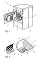
Figure 1 shows a view in perspective, with parts removed for clarity, of a rotary-drum laundry drier in accordance with the teachings of the present invention; -
Figure 2 shows a view in perspective, with parts in section and parts removed for clarity, of a detail of theFigure 1 rotary-drum laundry drier. - Number 1 in
Figure 1 indicates as a whole a home laundry drier substantially comprising a preferably, though not necessarily, parallelepiped-shapedouter box casing 2; an airtight, preferably, though not necessarily, cylindrical laundry drying tub or chamber (not shown) for housing the laundry to be dried, and which is fixed substantially horizontally insidecasing 2, directly facing a laundry loading and unloadingopening 2a formed in the front face ofcasing 2; adoor 3 hinged to the front face ofcasing 2 to rotate to and from a workposition closing opening 2a in the front face to seal the laundry drying tub; and a preferably, though not necessarily,cylindrical laundry drum 4 for housing the laundry for drying, and which is housed in axially rotating manner and preferably, though not necessarily, horizontally inside the drying tub. - More specifically, with reference to
Figures 1 and 2 ,laundry drum 4 is mounted for rotation about its longitudinal axis L, which, in the example shown, coincides with the longitudinal axis of the drying tub; is made of metal; has anend wall 4a and possibly a cylindricallateral wall 4b, which are perforated or at any rate permeable to air, to assist airflow into the drum; and preferably, though not necessarily, has a number of ribs orprojections 5 projecting towards the centre of the drum from the surface of cylindricallateral wall 4b. - In the example shown,
projections 5 extend, substantially parallel to longitudinal axis L, along the surface of cylindricallateral wall 4b, and are equally spaced angularly along the whole circumference of cylindricallateral wall 4b. - Laundry drier 1 also comprises an electric motor (not shown) or similar, which, on command, rotates
laundry drum 4 about longitudinal axis L inside the drying tub; and a closed-circuit, hot-air generator (not shown) housed insidecasing 2 and designed to circulate inside the drying tub andlaundry drum 4 a stream of hot air with a low humidity content, and which flows over, to rapidly dry, the laundry inside the drum. -
Casing 2, the drying tub,door 3,laundry drum 4, the electric motor, and the hot-air generator are commonly known parts in the industry, and therefore not described in detail. - With reference to
Figures 1 and 2 , laundry drier 1 also comprises aninternal jacket 6 of predetermined thickness, which is fixed firmly, but in easily removable manner, insidelaundry drum 4 to line and protect the surface of cylindricallateral wall 4b oflaundry drum 4. -
Jacket 6 substantially consists of asheet 7 of soft lining material of appropriate thickness, which is shaped to line the surface of cylindricallateral wall 4b oflaundry drum 4, preferably, though not necessary, with the exception of the areas occupied byprojections 5; and of fastening means 8 designed to fixsheet 7 of lining material firmly, but in easily removable manner, to the surface of cylindricallateral wall 4b. - In the example shown,
sheet 7 of lining material is defined by asheet 7 of plastic material of preferably, though not necessarily, 1 to 10 millimetre thickness, and is divided into a number of cylindrical sectors, each of which is shaped to completely line the surface of cylindricallateral wall 4b oflaundry drum 4 bounded laterally by twoadjacent projections 5. - More specifically, with reference to
Figure 2 ,sheet 7 of lining material in the example shown comprises a number of solid mats of open- or closed-cell plastic polymer foam (such as neoprene or polyurethane), each of which is 1 to 10 millimetres thick, is shaped to completely line the surface of cylindricallateral wall 4b oflaundry drum 4 bounded laterally by twoadjacent projections 5, and has, embedded in it, a number ofpermanent magnets 8 for securing the plastic polymer foam mat magnetically to the surface of cylindricallateral wall 4b oflaundry drum 4. - Obviously, at least cylindrical
lateral wall 4b oflaundry drum 4 must be made of metal. -
Permanent magnets 8 define the fastening means 8 ofjacket 6, and must be so arranged along the whole plasticpolymer foam mat 7 that the attraction force produced by interaction between the magnetic field generated bypermanent magnets 8 and the metal body oflaundry drum 4 is sufficient to ensure adhesion of the plasticpolymer foam mat 7 to the surface of cylindricallateral wall 4b of the drum. - In an alternative embodiment,
sheet 7 of lining material may comprise one or more sheets of extruded plastic mesh or perforated material to facilitate airflow through cylindricallateral wall 4b oflaundry drum 4, if this wall is also perforated or at any rate permeable to air. - In this case too, the sheets of extruded plastic mesh or perforated material may be 1 to 10 millimetres thick, and
permanent magnets 8 may be embedded in them to fix each sheet of extruded plastic material to the surface of cylindricallateral wall 4b oflaundry drum 4. - Operation of laundry drier 1 will be clear from the foregoing description, with no further explanation required, other than to state that
jacket 6 prevents the metal parts in the laundry rotating insidelaundry drum 4 from directly contacting cylindricallateral wall 4b of the drum, thus eliminating the noise typical of metal-on-metal impact. -
Sheet 7 of lining material may also have soundproofing properties to further deaden the noise produced by metal parts in the laundry rotating insidelaundry drum 4striking jacket 6, thus further reducing the noise level of the household appliance. - Using
permanent magnets 8 to fixsheet 7 of plastic material to the surface of cylindricallateral wall 4b oflaundry drum 4 is also highly versatile, and involves no change in the manufacturing process ofmetal laundry drum 4. - Using
permanent magnets 8,jacket 6 can also be applied to the laundry drums of existing driers, with all the advantages this entails. - Clearly, changes may be made to laundry drier 1 as described herein without, however, departing from the scope of the present invention.
- For example, laundry drier 1 is not provided with an airtight laundry drying tub or chamber, and the
laundry drum 4 is mounted in axially rotating manner directly insidebox casing 2. In this embodiment onlyend wall 4a of thelaundry drum 4 is perforated or permeable to air, and the front opening of thelaundry drum 4 directly faces the laundry loading and unloadingopening 2a in the front face ofbox casing 2. Obviously, when placed in its work position,door 3 seals in airtight manner directly the front opening oflaundry drum 4. - As concerns the
internal jacket 6, in an alternative embodimentpermanent magnets 8 may be replaced with press-studs or other click-on fastening devices, though these are obviously not so easy to use. - As regards
laundry drum 4, cylindricallateral wall 4b may be the only part of the drum made of metal.
Claims (10)
- A home laundry drier (1) comprising an outer box casing (2), and a rotary laundry drum (4) for housing the laundry for drying, and which is mounted for rotation about its longitudinal axis (L) inside said box casing (2); the laundry drum (4) being substantially cylindrical and said laundry drier (1) being characterized by also comprising a jacket (6) fixed firmly, but in easily removable manner, to the inside of the laundry drum (4) to line and protect the surface of the cylindrical lateral wall (4b) of said laundry drum (4).
- A laundry drier as claimed in Claim 1, characterized in that said jacket (6) comprises a sheet (7) of soft lining material of predetermined thickness, which is shaped to line the surface of the cylindrical lateral wall (4b) of the laundry drum (4); and fastening means (8) designed to fix said sheet (7) of lining material firmly, but in easily removable manner, to the surface of said cylindrical lateral wall (4b).
- A laundry drier as claimed in Claim 2, characterized in that said laundry drum (4) comprises a number of projections (5) projecting from the surface of the cylindrical lateral wall (4b) towards the centre of the laundry drum, and extending substantially parallel to the longitudinal axis (L) of said laundry drum; said sheet (7) of lining material being divided into a number of cylindrical sectors, each of which is shaped to completely line the surface of the cylindrical lateral wall (4b) of the laundry drum (4) bounded laterally by two adjacent projections (5).
- A laundry drier as claimed in Claim 2 or 3, characterized in that said sheet (7) of lining material is a sheet (7) of plastic material of predetermined thickness.
- A laundry drier as claimed in Claim 4, characterized in that said sheet (7) of plastic material is 1 to 10 millimetres thick.
- A laundry drier as claimed in any one of Claims 2 to 5, characterized in that said sheet (7) of lining material comprises at least one mat (7) of open- or closed-cell plastic polymer foam.
- A laundry drier as claimed in any one of Claims 2 to 5, characterized in that said sheet (7) of lining material comprises at least one sheet (7) of extruded plastic mesh or perforated material.
- A laundry drier as claimed in any one of the foregoing Claims, characterized in that at least the cylindrical lateral wall (4b) of said laundry drum (4) is made of metal.
- A laundry drier as claimed in Claim 8, characterized in that said fastening means (8) comprise a number of permanent magnets (8) arranged inside the sheet (7) of lining material to fix said sheet (7) of lining material magnetically to the surface of the cylindrical lateral wall (4b) of the laundry drum (4).
- A laundry drier as claimed in any one of Claims 2 to 9, characterized in that said sheet (7) of lining material is made of soundproofing material.
Priority Applications (5)
| Application Number | Priority Date | Filing Date | Title |
|---|---|---|---|
| ES07107260T ES2365256T3 (en) | 2007-04-30 | 2007-04-30 | DOMESTIC CLOTHES DRYER. |
| PL07107260T PL1988208T3 (en) | 2007-04-30 | 2007-04-30 | Home laundry drier |
| AT07107260T ATE512246T1 (en) | 2007-04-30 | 2007-04-30 | DRYER FOR HOUSEHOLD |
| EP07107260A EP1988208B1 (en) | 2007-04-30 | 2007-04-30 | Home laundry drier |
| RU2008117254/12A RU2467109C2 (en) | 2007-04-30 | 2008-04-29 | Household dryer for clothes |
Applications Claiming Priority (1)
| Application Number | Priority Date | Filing Date | Title |
|---|---|---|---|
| EP07107260A EP1988208B1 (en) | 2007-04-30 | 2007-04-30 | Home laundry drier |
Publications (2)
| Publication Number | Publication Date |
|---|---|
| EP1988208A1 true EP1988208A1 (en) | 2008-11-05 |
| EP1988208B1 EP1988208B1 (en) | 2011-06-08 |
Family
ID=38521268
Family Applications (1)
| Application Number | Title | Priority Date | Filing Date |
|---|---|---|---|
| EP07107260A Not-in-force EP1988208B1 (en) | 2007-04-30 | 2007-04-30 | Home laundry drier |
Country Status (5)
| Country | Link |
|---|---|
| EP (1) | EP1988208B1 (en) |
| AT (1) | ATE512246T1 (en) |
| ES (1) | ES2365256T3 (en) |
| PL (1) | PL1988208T3 (en) |
| RU (1) | RU2467109C2 (en) |
Cited By (1)
| Publication number | Priority date | Publication date | Assignee | Title |
|---|---|---|---|---|
| US20120291302A1 (en) * | 2011-05-16 | 2012-11-22 | Bsh Home Appliances Corporation | Noise-reducing laundry drum for a household appliance |
Citations (6)
| Publication number | Priority date | Publication date | Assignee | Title |
|---|---|---|---|---|
| US4254139A (en) * | 1979-12-20 | 1981-03-03 | Colgate-Palmolive Company | Laundry conditioner dispensing article |
| JPH02142599A (en) * | 1988-11-24 | 1990-05-31 | Hitachi Ltd | clothes dryer |
| JPH02265597A (en) * | 1989-04-07 | 1990-10-30 | Matsushita Electric Ind Co Ltd | clothes dryer |
| US6374509B1 (en) * | 2000-08-18 | 2002-04-23 | Richard W. Jackson, Sr. | Shoe holder for attaching a shoe to a dryer |
| CN1724787A (en) * | 2004-07-21 | 2006-01-25 | 乐金电子(天津)电器有限公司 | Drying drum of clothes drier |
| EP1696069A1 (en) * | 2005-02-23 | 2006-08-30 | Indesit Company S.p.A. | Laundry treatment household appliance having a rotating drum fitted with soft and/or elastic elements |
Family Cites Families (3)
| Publication number | Priority date | Publication date | Assignee | Title |
|---|---|---|---|---|
| US5623769A (en) * | 1996-01-31 | 1997-04-29 | Hayden; Richard | Device for drying objects in a dryer of clothes |
| DE10162918A1 (en) * | 2001-12-20 | 2003-07-03 | Bsh Bosch Siemens Hausgeraete | Drum for a laundry treatment machine |
| ES2260977B1 (en) * | 2003-07-15 | 2007-08-16 | Bsh Electrodomesticos España, S.A. | DRUM WASHER DRUM. |
-
2007
- 2007-04-30 AT AT07107260T patent/ATE512246T1/en not_active IP Right Cessation
- 2007-04-30 PL PL07107260T patent/PL1988208T3/en unknown
- 2007-04-30 EP EP07107260A patent/EP1988208B1/en not_active Not-in-force
- 2007-04-30 ES ES07107260T patent/ES2365256T3/en active Active
-
2008
- 2008-04-29 RU RU2008117254/12A patent/RU2467109C2/en not_active IP Right Cessation
Patent Citations (6)
| Publication number | Priority date | Publication date | Assignee | Title |
|---|---|---|---|---|
| US4254139A (en) * | 1979-12-20 | 1981-03-03 | Colgate-Palmolive Company | Laundry conditioner dispensing article |
| JPH02142599A (en) * | 1988-11-24 | 1990-05-31 | Hitachi Ltd | clothes dryer |
| JPH02265597A (en) * | 1989-04-07 | 1990-10-30 | Matsushita Electric Ind Co Ltd | clothes dryer |
| US6374509B1 (en) * | 2000-08-18 | 2002-04-23 | Richard W. Jackson, Sr. | Shoe holder for attaching a shoe to a dryer |
| CN1724787A (en) * | 2004-07-21 | 2006-01-25 | 乐金电子(天津)电器有限公司 | Drying drum of clothes drier |
| EP1696069A1 (en) * | 2005-02-23 | 2006-08-30 | Indesit Company S.p.A. | Laundry treatment household appliance having a rotating drum fitted with soft and/or elastic elements |
Cited By (1)
| Publication number | Priority date | Publication date | Assignee | Title |
|---|---|---|---|---|
| US20120291302A1 (en) * | 2011-05-16 | 2012-11-22 | Bsh Home Appliances Corporation | Noise-reducing laundry drum for a household appliance |
Also Published As
| Publication number | Publication date |
|---|---|
| ATE512246T1 (en) | 2011-06-15 |
| ES2365256T3 (en) | 2011-09-27 |
| PL1988208T3 (en) | 2011-11-30 |
| RU2467109C2 (en) | 2012-11-20 |
| EP1988208B1 (en) | 2011-06-08 |
| RU2008117254A (en) | 2009-11-10 |
Similar Documents
| Publication | Publication Date | Title |
|---|---|---|
| US7895771B2 (en) | Clothes dryer with thermal insulation pad | |
| CN101314912B (en) | Washing machine with dehumidification device and dehumidification method thereof | |
| CN1228496C (en) | Drum device for home appliance | |
| RU2466229C2 (en) | Dryer for laundry | |
| TWI342906B (en) | ||
| RU2452803C2 (en) | Drum dryer | |
| EP1988208B1 (en) | Home laundry drier | |
| TW200619456A (en) | Drum type washing and drying machine | |
| KR100619728B1 (en) | Sealing device for drum for clothes dryer | |
| KR101000689B1 (en) | Laundry dryer | |
| CN111979693A (en) | Device for washing and drying objects and method for operating such a device | |
| EP2107154A1 (en) | Household laundry washing and/or drying appliance | |
| KR101606663B1 (en) | Clothes dryer | |
| JP4768693B2 (en) | Dryer and washing dryer | |
| CA2506502C (en) | Laundry dryer with novel exhaust pipe installation structure | |
| JP2010057816A (en) | Washing and drying machine, and drying machine | |
| KR101047232B1 (en) | Drum device for home appliance | |
| KR101079921B1 (en) | Drum front sealing of dryer | |
| JP2008006127A (en) | Washing and drying machine | |
| KR102697545B1 (en) | kitchen hood and its control method | |
| KR20070078278A (en) | Fastening structure of motor bracket and base for clothes dryer | |
| KR100640844B1 (en) | Drum Washing Machine | |
| JP2013192659A (en) | Drying machine | |
| JP2010246709A (en) | Washing and drying machine | |
| KR101667578B1 (en) | Washing machine |
Legal Events
| Date | Code | Title | Description |
|---|---|---|---|
| PUAI | Public reference made under article 153(3) epc to a published international application that has entered the european phase |
Free format text: ORIGINAL CODE: 0009012 |
|
| AK | Designated contracting states |
Kind code of ref document: A1 Designated state(s): AT BE BG CH CY CZ DE DK EE ES FI FR GB GR HU IE IS IT LI LT LU LV MC MT NL PL PT RO SE SI SK TR |
|
| AX | Request for extension of the european patent |
Extension state: AL BA HR MK RS |
|
| 17P | Request for examination filed |
Effective date: 20090305 |
|
| 17Q | First examination report despatched |
Effective date: 20090527 |
|
| AKX | Designation fees paid |
Designated state(s): AT BE BG CH CY CZ DE DK EE ES FI FR GB GR HU IE IS IT LI LT LU LV MC MT NL PL PT RO SE SI SK TR |
|
| GRAP | Despatch of communication of intention to grant a patent |
Free format text: ORIGINAL CODE: EPIDOSNIGR1 |
|
| RAP1 | Party data changed (applicant data changed or rights of an application transferred) |
Owner name: ELECTROLUX HOME PRODUCTS CORPORATION N.V. |
|
| GRAS | Grant fee paid |
Free format text: ORIGINAL CODE: EPIDOSNIGR3 |
|
| GRAA | (expected) grant |
Free format text: ORIGINAL CODE: 0009210 |
|
| AK | Designated contracting states |
Kind code of ref document: B1 Designated state(s): AT BE BG CH CY CZ DE DK EE ES FI FR GB GR HU IE IS IT LI LT LU LV MC MT NL PL PT RO SE SI SK TR |
|
| REG | Reference to a national code |
Ref country code: GB Ref legal event code: FG4D |
|
| REG | Reference to a national code |
Ref country code: CH Ref legal event code: EP |
|
| RAP2 | Party data changed (patent owner data changed or rights of a patent transferred) |
Owner name: ELECTROLUX HOME PRODUCTS CORPORATION N.V. |
|
| REG | Reference to a national code |
Ref country code: IE Ref legal event code: FG4D |
|
| REG | Reference to a national code |
Ref country code: DE Ref legal event code: R096 Ref document number: 602007015061 Country of ref document: DE Effective date: 20110721 |
|
| REG | Reference to a national code |
Ref country code: ES Ref legal event code: FG2A Ref document number: 2365256 Country of ref document: ES Kind code of ref document: T3 Effective date: 20110927 |
|
| REG | Reference to a national code |
Ref country code: NL Ref legal event code: VDEP Effective date: 20110608 |
|
| PG25 | Lapsed in a contracting state [announced via postgrant information from national office to epo] |
Ref country code: SE Free format text: LAPSE BECAUSE OF FAILURE TO SUBMIT A TRANSLATION OF THE DESCRIPTION OR TO PAY THE FEE WITHIN THE PRESCRIBED TIME-LIMIT Effective date: 20110608 Ref country code: LT Free format text: LAPSE BECAUSE OF FAILURE TO SUBMIT A TRANSLATION OF THE DESCRIPTION OR TO PAY THE FEE WITHIN THE PRESCRIBED TIME-LIMIT Effective date: 20110608 |
|
| PG25 | Lapsed in a contracting state [announced via postgrant information from national office to epo] |
Ref country code: FI Free format text: LAPSE BECAUSE OF FAILURE TO SUBMIT A TRANSLATION OF THE DESCRIPTION OR TO PAY THE FEE WITHIN THE PRESCRIBED TIME-LIMIT Effective date: 20110608 Ref country code: SI Free format text: LAPSE BECAUSE OF FAILURE TO SUBMIT A TRANSLATION OF THE DESCRIPTION OR TO PAY THE FEE WITHIN THE PRESCRIBED TIME-LIMIT Effective date: 20110608 Ref country code: CY Free format text: LAPSE BECAUSE OF FAILURE TO SUBMIT A TRANSLATION OF THE DESCRIPTION OR TO PAY THE FEE WITHIN THE PRESCRIBED TIME-LIMIT Effective date: 20110608 Ref country code: AT Free format text: LAPSE BECAUSE OF FAILURE TO SUBMIT A TRANSLATION OF THE DESCRIPTION OR TO PAY THE FEE WITHIN THE PRESCRIBED TIME-LIMIT Effective date: 20110608 Ref country code: LV Free format text: LAPSE BECAUSE OF FAILURE TO SUBMIT A TRANSLATION OF THE DESCRIPTION OR TO PAY THE FEE WITHIN THE PRESCRIBED TIME-LIMIT Effective date: 20110608 Ref country code: GR Free format text: LAPSE BECAUSE OF FAILURE TO SUBMIT A TRANSLATION OF THE DESCRIPTION OR TO PAY THE FEE WITHIN THE PRESCRIBED TIME-LIMIT Effective date: 20110909 |
|
| REG | Reference to a national code |
Ref country code: PL Ref legal event code: T3 |
|
| PG25 | Lapsed in a contracting state [announced via postgrant information from national office to epo] |
Ref country code: NL Free format text: LAPSE BECAUSE OF FAILURE TO SUBMIT A TRANSLATION OF THE DESCRIPTION OR TO PAY THE FEE WITHIN THE PRESCRIBED TIME-LIMIT Effective date: 20110608 Ref country code: BE Free format text: LAPSE BECAUSE OF FAILURE TO SUBMIT A TRANSLATION OF THE DESCRIPTION OR TO PAY THE FEE WITHIN THE PRESCRIBED TIME-LIMIT Effective date: 20110608 |
|
| PG25 | Lapsed in a contracting state [announced via postgrant information from national office to epo] |
Ref country code: EE Free format text: LAPSE BECAUSE OF FAILURE TO SUBMIT A TRANSLATION OF THE DESCRIPTION OR TO PAY THE FEE WITHIN THE PRESCRIBED TIME-LIMIT Effective date: 20110608 Ref country code: IS Free format text: LAPSE BECAUSE OF FAILURE TO SUBMIT A TRANSLATION OF THE DESCRIPTION OR TO PAY THE FEE WITHIN THE PRESCRIBED TIME-LIMIT Effective date: 20111008 Ref country code: CZ Free format text: LAPSE BECAUSE OF FAILURE TO SUBMIT A TRANSLATION OF THE DESCRIPTION OR TO PAY THE FEE WITHIN THE PRESCRIBED TIME-LIMIT Effective date: 20110608 Ref country code: PT Free format text: LAPSE BECAUSE OF FAILURE TO SUBMIT A TRANSLATION OF THE DESCRIPTION OR TO PAY THE FEE WITHIN THE PRESCRIBED TIME-LIMIT Effective date: 20111010 |
|
| REG | Reference to a national code |
Ref country code: FR Ref legal event code: CA Effective date: 20120116 |
|
| PG25 | Lapsed in a contracting state [announced via postgrant information from national office to epo] |
Ref country code: SK Free format text: LAPSE BECAUSE OF FAILURE TO SUBMIT A TRANSLATION OF THE DESCRIPTION OR TO PAY THE FEE WITHIN THE PRESCRIBED TIME-LIMIT Effective date: 20110608 Ref country code: RO Free format text: LAPSE BECAUSE OF FAILURE TO SUBMIT A TRANSLATION OF THE DESCRIPTION OR TO PAY THE FEE WITHIN THE PRESCRIBED TIME-LIMIT Effective date: 20110608 |
|
| PLBE | No opposition filed within time limit |
Free format text: ORIGINAL CODE: 0009261 |
|
| STAA | Information on the status of an ep patent application or granted ep patent |
Free format text: STATUS: NO OPPOSITION FILED WITHIN TIME LIMIT |
|
| 26N | No opposition filed |
Effective date: 20120309 |
|
| PG25 | Lapsed in a contracting state [announced via postgrant information from national office to epo] |
Ref country code: DK Free format text: LAPSE BECAUSE OF FAILURE TO SUBMIT A TRANSLATION OF THE DESCRIPTION OR TO PAY THE FEE WITHIN THE PRESCRIBED TIME-LIMIT Effective date: 20110608 |
|
| REG | Reference to a national code |
Ref country code: DE Ref legal event code: R097 Ref document number: 602007015061 Country of ref document: DE Effective date: 20120309 |
|
| PG25 | Lapsed in a contracting state [announced via postgrant information from national office to epo] |
Ref country code: MC Free format text: LAPSE BECAUSE OF NON-PAYMENT OF DUE FEES Effective date: 20120430 |
|
| REG | Reference to a national code |
Ref country code: CH Ref legal event code: PL |
|
| PGFP | Annual fee paid to national office [announced via postgrant information from national office to epo] |
Ref country code: ES Payment date: 20120425 Year of fee payment: 6 |
|
| PG25 | Lapsed in a contracting state [announced via postgrant information from national office to epo] |
Ref country code: CH Free format text: LAPSE BECAUSE OF NON-PAYMENT OF DUE FEES Effective date: 20120430 Ref country code: LI Free format text: LAPSE BECAUSE OF NON-PAYMENT OF DUE FEES Effective date: 20120430 |
|
| PG25 | Lapsed in a contracting state [announced via postgrant information from national office to epo] |
Ref country code: IE Free format text: LAPSE BECAUSE OF NON-PAYMENT OF DUE FEES Effective date: 20120430 |
|
| PGFP | Annual fee paid to national office [announced via postgrant information from national office to epo] |
Ref country code: PL Payment date: 20130325 Year of fee payment: 7 |
|
| PG25 | Lapsed in a contracting state [announced via postgrant information from national office to epo] |
Ref country code: BG Free format text: LAPSE BECAUSE OF FAILURE TO SUBMIT A TRANSLATION OF THE DESCRIPTION OR TO PAY THE FEE WITHIN THE PRESCRIBED TIME-LIMIT Effective date: 20110908 |
|
| PG25 | Lapsed in a contracting state [announced via postgrant information from national office to epo] |
Ref country code: MT Free format text: LAPSE BECAUSE OF FAILURE TO SUBMIT A TRANSLATION OF THE DESCRIPTION OR TO PAY THE FEE WITHIN THE PRESCRIBED TIME-LIMIT Effective date: 20110608 |
|
| PG25 | Lapsed in a contracting state [announced via postgrant information from national office to epo] |
Ref country code: TR Free format text: LAPSE BECAUSE OF FAILURE TO SUBMIT A TRANSLATION OF THE DESCRIPTION OR TO PAY THE FEE WITHIN THE PRESCRIBED TIME-LIMIT Effective date: 20110608 |
|
| PG25 | Lapsed in a contracting state [announced via postgrant information from national office to epo] |
Ref country code: LU Free format text: LAPSE BECAUSE OF NON-PAYMENT OF DUE FEES Effective date: 20120430 |
|
| PG25 | Lapsed in a contracting state [announced via postgrant information from national office to epo] |
Ref country code: HU Free format text: LAPSE BECAUSE OF FAILURE TO SUBMIT A TRANSLATION OF THE DESCRIPTION OR TO PAY THE FEE WITHIN THE PRESCRIBED TIME-LIMIT Effective date: 20070430 |
|
| REG | Reference to a national code |
Ref country code: PL Ref legal event code: LAPE |
|
| PG25 | Lapsed in a contracting state [announced via postgrant information from national office to epo] |
Ref country code: PL Free format text: LAPSE BECAUSE OF NON-PAYMENT OF DUE FEES Effective date: 20140430 |
|
| REG | Reference to a national code |
Ref country code: FR Ref legal event code: PLFP Year of fee payment: 10 |
|
| PG25 | Lapsed in a contracting state [announced via postgrant information from national office to epo] |
Ref country code: ES Free format text: LAPSE BECAUSE OF NON-PAYMENT OF DUE FEES Effective date: 20140501 |
|
| PGFP | Annual fee paid to national office [announced via postgrant information from national office to epo] |
Ref country code: GB Payment date: 20160421 Year of fee payment: 10 |
|
| PGFP | Annual fee paid to national office [announced via postgrant information from national office to epo] |
Ref country code: FR Payment date: 20160421 Year of fee payment: 10 |
|
| PGFP | Annual fee paid to national office [announced via postgrant information from national office to epo] |
Ref country code: DE Payment date: 20170419 Year of fee payment: 11 |
|
| PGFP | Annual fee paid to national office [announced via postgrant information from national office to epo] |
Ref country code: IT Payment date: 20170424 Year of fee payment: 11 |
|
| GBPC | Gb: european patent ceased through non-payment of renewal fee |
Effective date: 20170430 |
|
| REG | Reference to a national code |
Ref country code: FR Ref legal event code: ST Effective date: 20171229 |
|
| PG25 | Lapsed in a contracting state [announced via postgrant information from national office to epo] |
Ref country code: FR Free format text: LAPSE BECAUSE OF NON-PAYMENT OF DUE FEES Effective date: 20170502 |
|
| PG25 | Lapsed in a contracting state [announced via postgrant information from national office to epo] |
Ref country code: GB Free format text: LAPSE BECAUSE OF NON-PAYMENT OF DUE FEES Effective date: 20170430 |
|
| REG | Reference to a national code |
Ref country code: DE Ref legal event code: R119 Ref document number: 602007015061 Country of ref document: DE |
|
| PG25 | Lapsed in a contracting state [announced via postgrant information from national office to epo] |
Ref country code: DE Free format text: LAPSE BECAUSE OF NON-PAYMENT OF DUE FEES Effective date: 20181101 |
|
| PG25 | Lapsed in a contracting state [announced via postgrant information from national office to epo] |
Ref country code: IT Free format text: LAPSE BECAUSE OF NON-PAYMENT OF DUE FEES Effective date: 20180430 |