EP1988022A1 - Wire curing diameter adjusting mechanism in binding machine - Google Patents
Wire curing diameter adjusting mechanism in binding machine Download PDFInfo
- Publication number
- EP1988022A1 EP1988022A1 EP07714605A EP07714605A EP1988022A1 EP 1988022 A1 EP1988022 A1 EP 1988022A1 EP 07714605 A EP07714605 A EP 07714605A EP 07714605 A EP07714605 A EP 07714605A EP 1988022 A1 EP1988022 A1 EP 1988022A1
- Authority
- EP
- European Patent Office
- Prior art keywords
- guide
- guide pin
- tying
- wire
- screw
- Prior art date
- Legal status (The legal status is an assumption and is not a legal conclusion. Google has not performed a legal analysis and makes no representation as to the accuracy of the status listed.)
- Granted
Links
Images



Classifications
-
- E—FIXED CONSTRUCTIONS
- E04—BUILDING
- E04G—SCAFFOLDING; FORMS; SHUTTERING; BUILDING IMPLEMENTS OR AIDS, OR THEIR USE; HANDLING BUILDING MATERIALS ON THE SITE; REPAIRING, BREAKING-UP OR OTHER WORK ON EXISTING BUILDINGS
- E04G21/00—Preparing, conveying, or working-up building materials or building elements in situ; Other devices or measures for constructional work
- E04G21/12—Mounting of reinforcing inserts; Prestressing
- E04G21/122—Machines for joining reinforcing bars
-
- E—FIXED CONSTRUCTIONS
- E04—BUILDING
- E04G—SCAFFOLDING; FORMS; SHUTTERING; BUILDING IMPLEMENTS OR AIDS, OR THEIR USE; HANDLING BUILDING MATERIALS ON THE SITE; REPAIRING, BREAKING-UP OR OTHER WORK ON EXISTING BUILDINGS
- E04G21/00—Preparing, conveying, or working-up building materials or building elements in situ; Other devices or measures for constructional work
- E04G21/12—Mounting of reinforcing inserts; Prestressing
- E04G21/122—Machines for joining reinforcing bars
- E04G21/123—Wire twisting tools
Definitions
- the present invention relates to a wire curl diameter adjusting mechanism for a tying machine.
- a desired curl diameter has to be formed.
- some of the members may tend to clog the wire.
- the wire clogging may easily occur in a front-end guide member which is the most important to form the curl diameter.
- a feed operation is stopped in a state where the front end of the wire does not protrude from the guide member.
- a problem arises in that the cut tying wire remains in the tying machine. Since it is not possible to remove the remaining wire to the outside, a user needs to detach the guide member so as to remove the remaining wire. At this time, after the detaching operation, it is necessary to again attach the guide member to an original position.
- One or more embodiments of the invention provide a wire curl diameter adjusting mechanism for a tying machine capable of keeping a curl diameter even when a user detaches members for forming the curl diameter and of reducing requiredprocessing precision for the members.
- a tying machine in a first aspect of the invention, is provided with: a feed part which feeds out a tying wire from a wire reel around which the tying wire is wound; a guide part which forms the tying wire fed out from a front end of the feed part in a loop shape around an object to be tied; and a twist part which grasps and twists the loop shaped tying wire.
- a guide member is screw-connected to a side of a fixed guide portion which is integrally formed with a tying machine body so as to protrude in a beak shape. The tying wire is fed out along a guide groove formed between the guide part and the guide member.
- the curl diameter of the wire fed out therefrom is adjusted by adjusting the position of the guide member.
- Two guide pins formed upright in the fixed guide portion are screw-fixed to guide pin fitting holes formed in the guide member while being received therein.
- One guide pin is fitted to the corresponding guide pin fitting hole with a play.
- a screw hole is formed through the inner surface of the guide pin fitting hole and the outer surface of the guide member.
- two screw holes may be formed on both sides on a line connecting the two guide pin fitting holes.
- the front end of the embedded screw may engage with the peripheral surface of a hollow pin fitted to the guide pin instead of the peripheral surface of the guide pin.
- the guide member since a gap is formed between the one guide pin and the guide pin fitting hole when the two guide pins of the fixed guide portion are fitted to the guide pin fitting holes of the guide member, the guide member can swing about the guide pin without a gap therebetween. Then, it is possible to adjust the angle of the guide member with respect to the fixed guide portion in such a manner that the embedded screws are respectively screw-inserted into the screw holes and a screw-insertion amount thereof is adjusted. Since the wire curl diameter is set by the angle of the guide member, it is possible to adjust the wire curl diameter. Then, the guide member may be screw-fixed to the guide pin after the position is adjusted.
- the positional relationship between the guide member and the guide pin is set at the same position as that before the detaching operation by use of the embedded screws. Accordingly, it is possible to attach the guide member so as to have the correct curl diameter without any additional adjustment.
- the correct curl diameter is obtained by adjusting the guide member, it is possible to reduce required processing precision for the members such as the guide pin of the fixed guide portion or the guide member.
- the number of the screw holes and the embedded screws may be two, respectively, and the angle of the guide member can be efficiently adjusted.
- the embedded screw directly engage with the hollow pin, it is possible to protect the guide pin.
- Reference Numeral 1 denotes a tying machine body and Reference Numeral 2 denotes a grip.
- the tying machine body 1 includes a feed part A which feeds out a tying wire 3 from a wire reel 4 around which the tying wire 3 is wound; a guide part B which allows the tying wire 3 fed out from the front end of the feed part A to be formed in a loop shape around an object to be tied 5; a twist part D which grasps and twists the tying wire 3 formed in a loop shape; and a cut part C which cuts the tying wire 3.
- the guide part B is integrally formed with the tying machine body 1 so as to protrude in a beak shape, and a wire receiving part 6 is formed at a position opposite to the guide part B.
- a feed motor (not shown) of the feed part A allows the tying wire 3 wound around the wire reel 4 to take a bending posture by using the guide part B which is integrally formed with the tying machine body 1 so as to protrude in a beak shape so that the tying wire 3 is formed in a loop shape at a space between the guide part B and the wire receiving part 6 provided at a position opposite to the guide part B.
- the tying wire 3 is cut by the cut part C.
- a twist hook 9 moves forward in a protruding manner from the center of the tying machine body 1 so as to grip both sides of a wire loop 3a and then twists the tying wire 3 by rotating a motor 9a of the twist part D so as to decrease a diameter of the tying wire 3, thereby tying the object to be tied 5 inserted in the wire loop 3a.
- a battery is attached to the lower portion of the grip 2 so as to drive the two motors 2.
- the tying wire 3 fed to the guide part B is first linearly guided by a base of the guide part B, and then is guided by the front end thereof so as to take a bending posture.
- the guide part B includes a guide plate 7 which is integrally formed with the tying machine body 1 so as to extend therefrom and a guide member 8 which is screw-connected to the guide plate 7. Then, a groove portion 10a is formed in a rear surface of the guide member 8 so as to have an L-shape in a sectional view.
- a guide groove 10 is curved between the groove portion 10a and a surface 10b of the guide plate 7 so as to have a U-shape in a sectional view, so that the tying wire 3 is guided along the guide groove 10. Accordingly, an angle of the guide groove 10 varies in accordance with an angle of the guide member 8 with respect to the guide plate 7. In addition, a curl diameter of the tying wire 3 varies in accordance with a different bending degree of the tying wire 3 passing through the guide groove 10.
- two guide pins 11 and 12 are formed upright at positions on the sides of a base and a front end of the surface 10b of the guide plate 7, respectively.
- Screw holes 17 are respectively formed at the centers of the guide pins 11 and 12.
- guide pin fitting holes 13 and 14 are formed in the guide member 8 so as to correspond to the two guide pins 11 and 12.
- Screw insertion holes 15 and 16 are respectively formed in the upper portions of the guide pin fitting holes 13 and 14.
- the base-side guide pin fitting hole 13 among the two guide pin fitting holes 13 and 14 is formed so that the inner diameter is approximately identical with the outer diameter of the guide pin 11 and the guide pin 11 is fittedto the guide pin fitting hole 13 without a gap therebetween.
- a hollow pin 18 is fitted to the front end-side guide pin 12, and the inner diameter of the front end-side guide pin fitting hole 14 is larger than the outer diameter of the guide pin 12 including the hollow pin 18, so that a gap S is formed between the guide pin 12 and the guide pin fitting hole 14.
- two screw holes (a first screw hole 20 and a second screw hole 21) are formed in the inner surfaces of the guide pin fitting holes 13 and 14 so as to penetrate the outer surface of the guide member 8.
- the screw holes 20 and 21 are formed on both sides on a line 24 connecting the centers of the two guide pin fitting holes 13 and 14, and embedded screws 22a and 22b are screw-inserted therein.
- the guide pins 11 and 12 of the guide plate 7 are received in the guide pin fitting holes 13 and 14 of the guide member 8.
- the base-side guide pin 11 is fitted to the guide pin fitting hole 13
- the front end-side guide pin 12 is fitted to the guide pin fitting hole 14 with a gap S therebetween in a state where the hollow pin 18 is fitted to the front end-side guide pin 12.
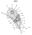
- the guide member 8 can swing about the base-side guide pin 11. Then, the first screw hole 20 and the second screw hole 21 are formed on both sides on a line 24 connecting the centers of the two guide pin fitting holes 13 and 14. Accordingly, when the front end of the embedded screw 22a screw-inserted into the first screw hole 20 engages with the peripheral surface of the hollow pin 18, if a screw-insertion amount thereof increases, the guide member 8 moves in a direction indicated by the arrow P shown in Fig. 5 .
- the guide member 8 moves in a direction indicated by the arrow Q shown in the same drawing. In this way, since the guide member 8 moves in the opposite directions indicated by the arrows P and Q by adjusting the screw-insertion amount of the two embedded screws 22a and 22b, it is possible to adjust the angle. Since an angle of the wire guide groove 10 of the guide member 8 is set by the angle of the guide member 8 and a curl diameter 3a of the tying wire 3 is set by the angle of the wire guide groove 10, the curl diameter 3a of the tying wire 3 is set by the angle of the guide member 8.
- the curl diameter 3a of the tying wire 3 is adjusted in this way at the factory shipment, for instance, even when a user has to detach the guide member 8 due to a wire clogging in use, it is possible to attach the guide member 8 in a state where the positional relationship of the guide member 8 and the guide pins 11 and 12 are the same as the positional relationship before the detaching operation in such a manner that the guide pin 11 is fitted to the guide pin fitting hole 13 formed in the guide member 8 and the guide pin 12 is fitted to the hollow pin 18 fixed to the guide pin fitting hole 14 by use of the configuration in which the hollow pin 18 is integrally formed with the guide member 8 and the position of the hollow pin 18 is set by the embedded screws 22a and 22b. Accordingly, it is possible to attach the guide member 8 so as to have the correct curl diameter 3a without any additional adjustment.
- the correct curl diameter 3a is obtained by adjusting the guide member 8, it is possible to reduce required processing precision for the members such as the guide pins 11 and 12 of the guide plate 7 or the guide member 8.
- the embedded screws 22a and 22b When the embedded screws 22a and 22b directly engage with the peripheral surface of the guide pin 12, scratches occur in the peripheral surface. For this reason, when the guide member 8 is exchanged several times, scratches occurred in the guide pin 12 become large.
- the hollow pin 18 is prepared so as to prevent scratches from occurring in the guide pin 12. Accordingly, the embedded screws 22a and 22b may directly engage with the guide pin 12.
- the number of the screw holes into which the embedded screws 22a and 22b are screw-inserted is not limited to two.
- the arrangement position of the screw hole is not limited to the positions on both sides on the line 24 connecting the centers of the two guide pin fitting holes 13 and 14.
- the present invention is applicable to a wire curl diameter adjusting mechanism for a tying machine.
Landscapes
- Engineering & Computer Science (AREA)
- Architecture (AREA)
- Mechanical Engineering (AREA)
- Civil Engineering (AREA)
- Structural Engineering (AREA)
- Basic Packing Technique (AREA)
- Wire Processing (AREA)
- Polishing Bodies And Polishing Tools (AREA)
- Manufacture Of Motors, Generators (AREA)
Abstract
Description
- The present invention relates to a wire curl diameter adjusting mechanism for a tying machine.
- Generally, in a rebar tying machine, it is important to reduce errors by ensuring a sufficient tying force. Accordingly, a desired curl diameter has to be formed. In order to obtain the desired curl diameter, it is necessary to decrease a non-uniform degree of the curl diameter during a production or to increase a tying width of the curl diameter of the tying machine itself.
- Various members are used to form the curl diameter, so that it is difficult to form a predetermined curl diameter due to tolerances of the members. In particular, when a diameter of a rebar as an object to be tied is large, it is necessary to increase the curl diameter. When the curl diameter is large, a problem arises in that a production is difficult because required processing precision becomes very strict.
- Therefore, it may be supposed that the above-described problem is handled by adjusting the attachment positions of the members used to form the curl diameter. Accordingly, it is possible to form the correct curl diameter by adjusting errors caused by the tolerances of the members (for instance, see
JP-A-07-132914 - Incidentally, in members for guiding a wire so as to form a curl diameter, some of the members may tend to clog the wire. Particularly, the wire clogging may easily occur in a front-end guide member which is the most important to form the curl diameter. For instance, when the tying machine is operated in a state where there is a very little remaining amount of the tying wire wound around a wire reel, a feed operation is stopped in a state where the front end of the wire does not protrude from the guide member. As a result, a problem arises in that the cut tying wire remains in the tying machine. Since it is not possible to remove the remaining wire to the outside, a user needs to detach the guide member so as to remove the remaining wire. At this time, after the detaching operation, it is necessary to again attach the guide member to an original position.
- However, as described above, since the wire curl diameter is adjusted by a very delicate operation and the curl diameter becomes different when the attachment position of the guide member is slightly different, it is very difficult for a user to attach the guide member to the original position. As a result, a problem arises in that troubles occur in a tying operation after the detaching operation.
- One or more embodiments of the invention provide a wire curl diameter adjusting mechanism for a tying machine capable of keeping a curl diameter even when a user detaches members for forming the curl diameter and of reducing requiredprocessing precision for the members.
- According to the one or more embodiments of the invention, in a first aspect of the invention, a tying machine is provided with: a feed part which feeds out a tying wire from a wire reel around which the tying wire is wound; a guide part which forms the tying wire fed out from a front end of the feed part in a loop shape around an object to be tied; and a twist part which grasps and twists the loop shaped tying wire. A guide member is screw-connected to a side of a fixed guide portion which is integrally formed with a tying machine body so as to protrude in a beak shape. The tying wire is fed out along a guide groove formed between the guide part and the guide member. The curl diameter of the wire fed out therefrom is adjusted by adjusting the position of the guide member. Two guide pins formed upright in the fixed guide portion are screw-fixed to guide pin fitting holes formed in the guide member while being received therein. One guide pin is fitted to the corresponding guide pin fitting hole with a play. A screw hole is formed through the inner surface of the guide pin fitting hole and the outer surface of the guide member. An angle of the guide member with respect to the fixed guide portion is adjusted in such a manner that a front end of an embedded screw screw-inserted in the screw hole engage with the peripheral surface of the guide pin.
- In a second aspect of the invention, two screw holes may be formed on both sides on a line connecting the two guide pin fitting holes.
- In a third aspect of the invention, the front end of the embedded screw may engage with the peripheral surface of a hollow pin fitted to the guide pin instead of the peripheral surface of the guide pin.
- According to the first aspect of the invention, since a gap is formed between the one guide pin and the guide pin fitting hole when the two guide pins of the fixed guide portion are fitted to the guide pin fitting holes of the guide member, the guide member can swing about the guide pin without a gap therebetween. Then, it is possible to adjust the angle of the guide member with respect to the fixed guide portion in such a manner that the embedded screws are respectively screw-inserted into the screw holes and a screw-insertion amount thereof is adjusted. Since the wire curl diameter is set by the angle of the guide member, it is possible to adjust the wire curl diameter. Then, the guide member may be screw-fixed to the guide pin after the position is adjusted.
- When attaching the guide member after the detaching operation, the positional relationship between the guide member and the guide pin is set at the same position as that before the detaching operation by use of the embedded screws. Accordingly, it is possible to attach the guide member so as to have the correct curl diameter without any additional adjustment.
- Since the correct curl diameter is obtained by adjusting the guide member, it is possible to reduce required processing precision for the members such as the guide pin of the fixed guide portion or the guide member.
- According to the second aspect of the invention, since two screw holes are formed on both sides on the line connecting the guide pin fitting holes, the number of the screw holes and the embedded screws may be two, respectively, and the angle of the guide member can be efficiently adjusted.
- According to the third aspect of the invention, since the embedded screw directly engage with the hollow pin, it is possible to protect the guide pin.
- Other aspects and advantages of the invention will be apparent from the following description, the drawings and the claims.
-
- [
Fig. 1] Fig. 1 is a longitudinal sectional diagram illustrating a tying machine related to the invention. - [
Fig. 2] Fig. 2 is an enlarged diagram taken along the line II-II shown inFig. 1 . - [
Fig. 3] Fig. 3 is an enlarged diagram illustrating a main part shown inFig. 1 . - [
Fig. 4] Fig. 4 is an enlarged sectional diagram taken along the line IV-IV shown inFig. 3 . - [
Fig. 5] Fig. 5 is a longitudinal sectional diagram illustrating a guide member and a guide pin. - [
Fig. 6] Fig. 6 is an exploded sectional diagram illustrating a guide plate and the guide member. -
- 1: TYING MACHINE BODY
- 3: TYING WIRE
- 7: GUIDE PLATE
- 8: GUIDE MEMBER
- 10: WIRE GUIDE GROOVE
- 11: FIRST GUIDE PIN
- 12: SECOND GUIDE PIN
- 13: FIRST GUIDE PIN FITTING HOLE
- 14: SECOND GUIDE PIN FITTING HOLE
- 20: FIRST SCREW HOLE
- 21: SECOND SCREW HOLE
- 22a, 22b: EMBEDDED SCREW
- Hereinafter, an exemplary embodiment of the invention will be described with reference to the accompanying drawings.
- In
Fig. 1 ,Reference Numeral 1 denotes a tying machine body andReference Numeral 2 denotes a grip. Thetying machine body 1 includes a feed part A which feeds out atying wire 3 from a wire reel 4 around which thetying wire 3 is wound; a guide part B which allows thetying wire 3 fed out from the front end of the feed part A to be formed in a loop shape around an object to be tied 5; a twist part D which grasps and twists thetying wire 3 formed in a loop shape; and a cut part C which cuts thetying wire 3. In addition, the guide part B is integrally formed with the tyingmachine body 1 so as to protrude in a beak shape, and a wire receiving part 6 is formed at a position opposite to the guide part B. Then, a feed motor (not shown) of the feed part A allows the tyingwire 3 wound around the wire reel 4 to take a bending posture by using the guide part B which is integrally formed with the tyingmachine body 1 so as to protrude in a beak shape so that the tyingwire 3 is formed in a loop shape at a space between the guide part B and the wire receiving part 6 provided at a position opposite to the guide part B. Subsequently, the tyingwire 3 is cut by the cut part C. Subsequently, a twist hook 9 moves forward in a protruding manner from the center of the tyingmachine body 1 so as to grip both sides of awire loop 3a and then twists the tyingwire 3 by rotating a motor 9a of the twist part D so as to decrease a diameter of the tyingwire 3, thereby tying the object to be tied 5 inserted in thewire loop 3a. A battery is attached to the lower portion of thegrip 2 so as to drive the twomotors 2. The above-described mechanism is already known. - Incidentally, as shown in
Fig. 2 , the tyingwire 3 fed to the guide part B is first linearly guided by a base of the guide part B, and then is guided by the front end thereof so as to take a bending posture. As shown inFigs. 3 and 4 , the guide part B includes aguide plate 7 which is integrally formed with the tyingmachine body 1 so as to extend therefrom and aguide member 8 which is screw-connected to theguide plate 7. Then, agroove portion 10a is formed in a rear surface of theguide member 8 so as to have an L-shape in a sectional view. Aguide groove 10 is curved between thegroove portion 10a and asurface 10b of theguide plate 7 so as to have a U-shape in a sectional view, so that the tyingwire 3 is guided along theguide groove 10. Accordingly, an angle of theguide groove 10 varies in accordance with an angle of theguide member 8 with respect to theguide plate 7. In addition, a curl diameter of the tyingwire 3 varies in accordance with a different bending degree of the tyingwire 3 passing through theguide groove 10. - That is, as shown in
Figs. 3 to 6 , two guide pins 11 and 12 (afirst guide pin 11 and a second guide pin 12) are formed upright at positions on the sides of a base and a front end of thesurface 10b of theguide plate 7, respectively. Screw holes 17 are respectively formed at the centers of the guide pins 11 and 12. On the other hand, guide pinfitting holes 13 and 14 (afirst guide pin 13 and a second guide pin 14) are formed in theguide member 8 so as to correspond to the two guide pins 11 and 12. Screw insertion holes 15 and 16 are respectively formed in the upper portions of the guide pinfitting holes - Incidentally, the base-side guide pin
fitting hole 13 among the two guide pinfitting holes guide pin 11 and theguide pin 11 is fittedto the guide pinfitting hole 13 without a gap therebetween. On the contrary, ahollow pin 18 is fitted to the front end-side guide pin 12, and the inner diameter of the front end-side guide pinfitting hole 14 is larger than the outer diameter of theguide pin 12 including thehollow pin 18, so that a gap S is formed between theguide pin 12 and the guide pinfitting hole 14. - Next, two screw holes (a
first screw hole 20 and a second screw hole 21) are formed in the inner surfaces of the guide pinfitting holes guide member 8. The screw holes 20 and 21 are formed on both sides on aline 24 connecting the centers of the two guide pinfitting holes screws - When attaching the
guide member 8 with the above-described configuration to theguide plate 7 in a factory, the guide pins 11 and 12 of theguide plate 7 are received in the guide pinfitting holes guide member 8. At this time, the base-side guide pin 11 is fitted to the guide pinfitting hole 13, and the front end-side guide pin 12 is fitted to the guide pinfitting hole 14 with a gap S therebetween in a state where thehollow pin 18 is fitted to the front end-side guide pin 12. - Since the gap S is formed between the
hollow pin 18 and the guide pinfitting holes guide member 8 can swing about the base-side guide pin 11. Then, thefirst screw hole 20 and thesecond screw hole 21 are formed on both sides on aline 24 connecting the centers of the two guide pinfitting holes screw 22a screw-inserted into thefirst screw hole 20 engages with the peripheral surface of thehollow pin 18, if a screw-insertion amount thereof increases, theguide member 8 moves in a direction indicated by the arrow P shown inFig. 5 . Additionally, when the front end of the embeddedscrew 22b screw-inserted into thesecond screw hole 21 engages with the peripheral surface of thehollow pin 18, if a screw-insertion amount thereof increases, theguide member 8 moves in a direction indicated by the arrow Q shown in the same drawing. In this way, since theguide member 8 moves in the opposite directions indicated by the arrows P and Q by adjusting the screw-insertion amount of the two embeddedscrews wire guide groove 10 of theguide member 8 is set by the angle of theguide member 8 and acurl diameter 3a of the tyingwire 3 is set by the angle of thewire guide groove 10, thecurl diameter 3a of the tyingwire 3 is set by the angle of theguide member 8. Accordingly, it is possible to adjust thecurl diameter 3a of the tyingwire 3 by adjusting the angle of theguide member 8. Then, as shown inFig. 3 , fixedscrews fitting holes - Since the
curl diameter 3a of the tyingwire 3 is adjusted in this way at the factory shipment, for instance, even when a user has to detach theguide member 8 due to a wire clogging in use, it is possible to attach theguide member 8 in a state where the positional relationship of theguide member 8 and the guide pins 11 and 12 are the same as the positional relationship before the detaching operation in such a manner that theguide pin 11 is fitted to the guide pinfitting hole 13 formed in theguide member 8 and theguide pin 12 is fitted to thehollow pin 18 fixed to the guide pinfitting hole 14 by use of the configuration in which thehollow pin 18 is integrally formed with theguide member 8 and the position of thehollow pin 18 is set by the embeddedscrews guide member 8 so as to have thecorrect curl diameter 3a without any additional adjustment. - Since the
correct curl diameter 3a is obtained by adjusting theguide member 8, it is possible to reduce required processing precision for the members such as the guide pins 11 and 12 of theguide plate 7 or theguide member 8. - When the embedded
screws guide pin 12, scratches occur in the peripheral surface. For this reason, when theguide member 8 is exchanged several times, scratches occurred in theguide pin 12 become large. Thehollow pin 18 is prepared so as to prevent scratches from occurring in theguide pin 12. Accordingly, the embeddedscrews guide pin 12. - The number of the screw holes into which the embedded
screws - The arrangement position of the screw hole is not limited to the positions on both sides on the
line 24 connecting the centers of the two guide pinfitting holes - While the invention has been described with reference to the specific embodiment, it will be obvious to those skilled in the art that various changes and modification may be made therein without departing from the present invention.
- This application is based on a Japanese Patent application No.
2006-043773 filed on February 21, 2006 - The present invention is applicable to a wire curl diameter adjusting mechanism for a tying machine.
Claims (6)
- A tying machine comprising:a feed part that feeds out a tying wire from a wire reel around which the tying wire is wound;a guide part that forms the tying wire fed out from a front end of the feed part in a loop shape around an object to be tied; anda twist part that grasps and twists the loop shaped tying wire,wherein the guide part includes:a fixed guide portion integrally formed with a tying machine body and protruding from the tying machine body;a guide member provided on a side of the fixed guide portion;a first guide pin fitting hole;a second guide pin fitting hole;a first guide pin that is received in the first guide pin fitting hole;a second guide pin that is received in the second guide pin fitting hole with a play; anda screw hole penetrating from an inner surface of the second guide pin fitting hole to an outer surface of the guide member, andwherein an angle of the guide member with respect to the fixed guide portion is adjusted by engaging a front end of an embedded screw screw-inserted in the screw hole with the second guide pin.
- The tying machine according to Claim 1, wherein the first guide pin is fitted to the first guide pin fitting hole without a gap therebetween.
- The tying machine according to Claim 1, wherein the first and second guide pin fitting holes are formed in the guide member, and
wherein the first and second guide pins are provided in the fixed guide portion. - The tying machine according to Claim 1, wherein the screw hole comprises a first screw hole formed on one side of a line connecting centers of the first and second guide pin fitting holes and a second screw hole formed on the other side thereof.
- The tying machine according to Claim 1, wherein the front end of the embedded screw engages with a peripheral surface of the second guide pin.
- The tying machine according to Claim 1, wherein the front end of the embedded screw engages with the second guide pin through a peripheral surface of a hollow pin fitted to the second guide pin.
Applications Claiming Priority (2)
| Application Number | Priority Date | Filing Date | Title |
|---|---|---|---|
| JP2006043773A JP4760439B2 (en) | 2006-02-21 | 2006-02-21 | Curling diameter adjustment mechanism of wire in binding machine |
| PCT/JP2007/053105 WO2007097342A1 (en) | 2006-02-21 | 2007-02-20 | Wire curing diameter adjusting mechanism in binding machine |
Publications (3)
| Publication Number | Publication Date |
|---|---|
| EP1988022A1 true EP1988022A1 (en) | 2008-11-05 |
| EP1988022A4 EP1988022A4 (en) | 2009-10-14 |
| EP1988022B1 EP1988022B1 (en) | 2011-12-28 |
Family
ID=38437381
Family Applications (1)
| Application Number | Title | Priority Date | Filing Date |
|---|---|---|---|
| EP07714605A Active EP1988022B1 (en) | 2006-02-21 | 2007-02-20 | Wire curing diameter adjusting mechanism in binding machine |
Country Status (8)
| Country | Link |
|---|---|
| US (1) | US8033303B2 (en) |
| EP (1) | EP1988022B1 (en) |
| JP (1) | JP4760439B2 (en) |
| CN (1) | CN101389535B (en) |
| AT (1) | ATE538999T1 (en) |
| AU (1) | AU2007218633B2 (en) |
| ES (1) | ES2376123T3 (en) |
| WO (1) | WO2007097342A1 (en) |
Cited By (1)
| Publication number | Priority date | Publication date | Assignee | Title |
|---|---|---|---|---|
| CN106592983A (en) * | 2016-12-02 | 2017-04-26 | 台州市新大陆电子科技有限公司 | Integrated wire discharge and guide mechanism and rebar tying machine |
Families Citing this family (8)
| Publication number | Priority date | Publication date | Assignee | Title |
|---|---|---|---|---|
| JP5182212B2 (en) * | 2009-05-12 | 2013-04-17 | マックス株式会社 | Rebar binding machine |
| TWI516415B (en) | 2008-12-12 | 2016-01-11 | 美克司股份有限公司 | Reinforcing bar binding machine |
| CN102441625B (en) * | 2011-09-16 | 2014-10-15 | 陆福军 | Wire cutting mechanism for full-automatic rebar tying machine |
| JP6926446B2 (en) * | 2016-11-10 | 2021-08-25 | マックス株式会社 | Cable ties |
| US11365552B2 (en) | 2017-06-07 | 2022-06-21 | Max Co., Ltd. | Binding machine |
| JP7354688B2 (en) | 2018-09-07 | 2023-10-03 | マックス株式会社 | tying machine |
| CN213603506U (en) * | 2020-10-10 | 2021-07-06 | 宁波欣仪伟业进出口有限公司 | Binding machine |
| CN112449934A (en) * | 2020-10-10 | 2021-03-09 | 宁波欣仪伟业进出口有限公司 | Bundling method of intelligent bundling machine |
Family Cites Families (5)
| Publication number | Priority date | Publication date | Assignee | Title |
|---|---|---|---|---|
| US5279336A (en) | 1992-05-21 | 1994-01-18 | Max Co., Ltd. | Wire binder |
| JP3393684B2 (en) * | 1993-08-16 | 2003-04-07 | 株式会社エスディーコーポレーション | Article binding method and binding apparatus |
| JP3077731B2 (en) * | 1993-11-08 | 2000-08-14 | マックス株式会社 | Guide mechanism for the binding wire in the binding machine |
| JP2731812B2 (en) * | 1995-04-08 | 1998-03-25 | 有限会社ヤヒロコーポレーション | Reinforcing mesh binding machine |
| JP3496463B2 (en) * | 1997-06-18 | 2004-02-09 | マックス株式会社 | Wire twisting device for rebar binding machine |
-
2006
- 2006-02-21 JP JP2006043773A patent/JP4760439B2/en not_active Expired - Lifetime
-
2007
- 2007-02-20 WO PCT/JP2007/053105 patent/WO2007097342A1/en not_active Ceased
- 2007-02-20 AU AU2007218633A patent/AU2007218633B2/en active Active
- 2007-02-20 CN CN200780006281XA patent/CN101389535B/en active Active
- 2007-02-20 AT AT07714605T patent/ATE538999T1/en active
- 2007-02-20 EP EP07714605A patent/EP1988022B1/en active Active
- 2007-02-20 ES ES07714605T patent/ES2376123T3/en active Active
- 2007-02-20 US US12/279,893 patent/US8033303B2/en active Active
Cited By (2)
| Publication number | Priority date | Publication date | Assignee | Title |
|---|---|---|---|---|
| CN106592983A (en) * | 2016-12-02 | 2017-04-26 | 台州市新大陆电子科技有限公司 | Integrated wire discharge and guide mechanism and rebar tying machine |
| CN106592983B (en) * | 2016-12-02 | 2019-03-01 | 台州市新大陆电子科技有限公司 | An integrated wire guide wire mechanism and steel bar binding machine |
Also Published As
| Publication number | Publication date |
|---|---|
| US20100224278A1 (en) | 2010-09-09 |
| US8033303B2 (en) | 2011-10-11 |
| EP1988022A4 (en) | 2009-10-14 |
| CN101389535A (en) | 2009-03-18 |
| AU2007218633B2 (en) | 2011-06-16 |
| CN101389535B (en) | 2011-03-23 |
| ES2376123T3 (en) | 2012-03-09 |
| JP4760439B2 (en) | 2011-08-31 |
| AU2007218633A1 (en) | 2007-08-30 |
| ATE538999T1 (en) | 2012-01-15 |
| EP1988022B1 (en) | 2011-12-28 |
| WO2007097342A1 (en) | 2007-08-30 |
| JP2007223615A (en) | 2007-09-06 |
Similar Documents
| Publication | Publication Date | Title |
|---|---|---|
| EP1988022B1 (en) | Wire curing diameter adjusting mechanism in binding machine | |
| US5415955A (en) | Structure for holding a battery pack on an electronic apparatus | |
| US20120227270A1 (en) | Bush cutter and protective cover for the same | |
| CN108069067B (en) | Bundling machine and auxiliary component for bundling machine | |
| JP2005187071A (en) | Rachet-type binding tool | |
| JP5149127B2 (en) | Rebar binding machine | |
| JP2005160223A (en) | Cable tie fixing structure | |
| EP0656501A2 (en) | Fastener for wire harness | |
| WO2017134766A1 (en) | Sealing structure and electricity meter | |
| JP4312042B2 (en) | Cable tie fixing structure | |
| JP2003175904A (en) | Reinforcing bar binding machine and reel used for the same | |
| JP2024115425A (en) | Rebar Tying Machine | |
| US6622768B2 (en) | Correction tape roll device | |
| JPWO2003028918A1 (en) | Reinforcing bar binding machine and reel used therefor | |
| CN110155402B (en) | Bundling machine | |
| EP2311648A1 (en) | Transfer device | |
| JP2008202390A (en) | Wire reel of reinforcement binder | |
| JPH11309288A (en) | Sewing machine and sewing machine needle holding device | |
| JP2000340272A (en) | Pin and winding connection structure | |
| EP4477817A1 (en) | Binding machine | |
| JP5144377B2 (en) | Reinforcing bar binding device and binding wire | |
| JP3134546U (en) | String bundle holding device | |
| CN122070193A (en) | Tool, tool cover, and tool locking body | |
| JP3071424U (en) | cabinet | |
| JP2000209752A (en) | Wire bundle holding jig |
Legal Events
| Date | Code | Title | Description |
|---|---|---|---|
| PUAI | Public reference made under article 153(3) epc to a published international application that has entered the european phase |
Free format text: ORIGINAL CODE: 0009012 |
|
| 17P | Request for examination filed |
Effective date: 20080731 |
|
| AK | Designated contracting states |
Kind code of ref document: A1 Designated state(s): AT BE BG CH CY CZ DE DK EE ES FI FR GB GR HU IE IS IT LI LT LU LV MC NL PL PT RO SE SI SK TR |
|
| RA4 | Supplementary search report drawn up and despatched (corrected) |
Effective date: 20090914 |
|
| 17Q | First examination report despatched |
Effective date: 20091127 |
|
| GRAP | Despatch of communication of intention to grant a patent |
Free format text: ORIGINAL CODE: EPIDOSNIGR1 |
|
| DAX | Request for extension of the european patent (deleted) | ||
| GRAS | Grant fee paid |
Free format text: ORIGINAL CODE: EPIDOSNIGR3 |
|
| GRAA | (expected) grant |
Free format text: ORIGINAL CODE: 0009210 |
|
| AK | Designated contracting states |
Kind code of ref document: B1 Designated state(s): AT BE BG CH CY CZ DE DK EE ES FI FR GB GR HU IE IS IT LI LT LU LV MC NL PL PT RO SE SI SK TR |
|
| REG | Reference to a national code |
Ref country code: GB Ref legal event code: FG4D |
|
| REG | Reference to a national code |
Ref country code: CH Ref legal event code: EP |
|
| REG | Reference to a national code |
Ref country code: AT Ref legal event code: REF Ref document number: 538999 Country of ref document: AT Kind code of ref document: T Effective date: 20120115 |
|
| REG | Reference to a national code |
Ref country code: IE Ref legal event code: FG4D |
|
| REG | Reference to a national code |
Ref country code: ES Ref legal event code: FG2A Ref document number: 2376123 Country of ref document: ES Kind code of ref document: T3 Effective date: 20120309 |
|
| REG | Reference to a national code |
Ref country code: DE Ref legal event code: R096 Ref document number: 602007019666 Country of ref document: DE Effective date: 20120322 |
|
| REG | Reference to a national code |
Ref country code: NL Ref legal event code: VDEP Effective date: 20111228 |
|
| REG | Reference to a national code |
Ref country code: SE Ref legal event code: TRGR |
|
| PG25 | Lapsed in a contracting state [announced via postgrant information from national office to epo] |
Ref country code: LT Free format text: LAPSE BECAUSE OF FAILURE TO SUBMIT A TRANSLATION OF THE DESCRIPTION OR TO PAY THE FEE WITHIN THE PRESCRIBED TIME-LIMIT Effective date: 20111228 |
|
| LTIE | Lt: invalidation of european patent or patent extension |
Effective date: 20111228 |
|
| PG25 | Lapsed in a contracting state [announced via postgrant information from national office to epo] |
Ref country code: GR Free format text: LAPSE BECAUSE OF FAILURE TO SUBMIT A TRANSLATION OF THE DESCRIPTION OR TO PAY THE FEE WITHIN THE PRESCRIBED TIME-LIMIT Effective date: 20120329 Ref country code: SI Free format text: LAPSE BECAUSE OF FAILURE TO SUBMIT A TRANSLATION OF THE DESCRIPTION OR TO PAY THE FEE WITHIN THE PRESCRIBED TIME-LIMIT Effective date: 20111228 Ref country code: LV Free format text: LAPSE BECAUSE OF FAILURE TO SUBMIT A TRANSLATION OF THE DESCRIPTION OR TO PAY THE FEE WITHIN THE PRESCRIBED TIME-LIMIT Effective date: 20111228 |
|
| PG25 | Lapsed in a contracting state [announced via postgrant information from national office to epo] |
Ref country code: BE Free format text: LAPSE BECAUSE OF FAILURE TO SUBMIT A TRANSLATION OF THE DESCRIPTION OR TO PAY THE FEE WITHIN THE PRESCRIBED TIME-LIMIT Effective date: 20111228 Ref country code: CY Free format text: LAPSE BECAUSE OF FAILURE TO SUBMIT A TRANSLATION OF THE DESCRIPTION OR TO PAY THE FEE WITHIN THE PRESCRIBED TIME-LIMIT Effective date: 20111228 |
|
| PG25 | Lapsed in a contracting state [announced via postgrant information from national office to epo] |
Ref country code: CZ Free format text: LAPSE BECAUSE OF FAILURE TO SUBMIT A TRANSLATION OF THE DESCRIPTION OR TO PAY THE FEE WITHIN THE PRESCRIBED TIME-LIMIT Effective date: 20111228 Ref country code: EE Free format text: LAPSE BECAUSE OF FAILURE TO SUBMIT A TRANSLATION OF THE DESCRIPTION OR TO PAY THE FEE WITHIN THE PRESCRIBED TIME-LIMIT Effective date: 20111228 Ref country code: SK Free format text: LAPSE BECAUSE OF FAILURE TO SUBMIT A TRANSLATION OF THE DESCRIPTION OR TO PAY THE FEE WITHIN THE PRESCRIBED TIME-LIMIT Effective date: 20111228 Ref country code: IS Free format text: LAPSE BECAUSE OF FAILURE TO SUBMIT A TRANSLATION OF THE DESCRIPTION OR TO PAY THE FEE WITHIN THE PRESCRIBED TIME-LIMIT Effective date: 20120428 Ref country code: NL Free format text: LAPSE BECAUSE OF FAILURE TO SUBMIT A TRANSLATION OF THE DESCRIPTION OR TO PAY THE FEE WITHIN THE PRESCRIBED TIME-LIMIT Effective date: 20111228 Ref country code: BG Free format text: LAPSE BECAUSE OF FAILURE TO SUBMIT A TRANSLATION OF THE DESCRIPTION OR TO PAY THE FEE WITHIN THE PRESCRIBED TIME-LIMIT Effective date: 20120328 |
|
| PG25 | Lapsed in a contracting state [announced via postgrant information from national office to epo] |
Ref country code: PT Free format text: LAPSE BECAUSE OF FAILURE TO SUBMIT A TRANSLATION OF THE DESCRIPTION OR TO PAY THE FEE WITHIN THE PRESCRIBED TIME-LIMIT Effective date: 20120430 Ref country code: RO Free format text: LAPSE BECAUSE OF FAILURE TO SUBMIT A TRANSLATION OF THE DESCRIPTION OR TO PAY THE FEE WITHIN THE PRESCRIBED TIME-LIMIT Effective date: 20111228 Ref country code: PL Free format text: LAPSE BECAUSE OF FAILURE TO SUBMIT A TRANSLATION OF THE DESCRIPTION OR TO PAY THE FEE WITHIN THE PRESCRIBED TIME-LIMIT Effective date: 20111228 |
|
| REG | Reference to a national code |
Ref country code: AT Ref legal event code: MK05 Ref document number: 538999 Country of ref document: AT Kind code of ref document: T Effective date: 20111228 |
|
| PG25 | Lapsed in a contracting state [announced via postgrant information from national office to epo] |
Ref country code: MC Free format text: LAPSE BECAUSE OF NON-PAYMENT OF DUE FEES Effective date: 20120229 |
|
| REG | Reference to a national code |
Ref country code: CH Ref legal event code: PL |
|
| PG25 | Lapsed in a contracting state [announced via postgrant information from national office to epo] |
Ref country code: CH Free format text: LAPSE BECAUSE OF NON-PAYMENT OF DUE FEES Effective date: 20120229 Ref country code: LI Free format text: LAPSE BECAUSE OF NON-PAYMENT OF DUE FEES Effective date: 20120229 Ref country code: DK Free format text: LAPSE BECAUSE OF FAILURE TO SUBMIT A TRANSLATION OF THE DESCRIPTION OR TO PAY THE FEE WITHIN THE PRESCRIBED TIME-LIMIT Effective date: 20111228 |
|
| PLBE | No opposition filed within time limit |
Free format text: ORIGINAL CODE: 0009261 |
|
| STAA | Information on the status of an ep patent application or granted ep patent |
Free format text: STATUS: NO OPPOSITION FILED WITHIN TIME LIMIT |
|
| REG | Reference to a national code |
Ref country code: IE Ref legal event code: MM4A |
|
| PG25 | Lapsed in a contracting state [announced via postgrant information from national office to epo] |
Ref country code: IT Free format text: LAPSE BECAUSE OF FAILURE TO SUBMIT A TRANSLATION OF THE DESCRIPTION OR TO PAY THE FEE WITHIN THE PRESCRIBED TIME-LIMIT Effective date: 20111228 |
|
| 26N | No opposition filed |
Effective date: 20121001 |
|
| REG | Reference to a national code |
Ref country code: DE Ref legal event code: R097 Ref document number: 602007019666 Country of ref document: DE Effective date: 20121001 |
|
| PG25 | Lapsed in a contracting state [announced via postgrant information from national office to epo] |
Ref country code: IE Free format text: LAPSE BECAUSE OF NON-PAYMENT OF DUE FEES Effective date: 20120220 Ref country code: AT Free format text: LAPSE BECAUSE OF FAILURE TO SUBMIT A TRANSLATION OF THE DESCRIPTION OR TO PAY THE FEE WITHIN THE PRESCRIBED TIME-LIMIT Effective date: 20111228 |
|
| PG25 | Lapsed in a contracting state [announced via postgrant information from national office to epo] |
Ref country code: FI Free format text: LAPSE BECAUSE OF FAILURE TO SUBMIT A TRANSLATION OF THE DESCRIPTION OR TO PAY THE FEE WITHIN THE PRESCRIBED TIME-LIMIT Effective date: 20111228 |
|
| PG25 | Lapsed in a contracting state [announced via postgrant information from national office to epo] |
Ref country code: TR Free format text: LAPSE BECAUSE OF FAILURE TO SUBMIT A TRANSLATION OF THE DESCRIPTION OR TO PAY THE FEE WITHIN THE PRESCRIBED TIME-LIMIT Effective date: 20111228 |
|
| PG25 | Lapsed in a contracting state [announced via postgrant information from national office to epo] |
Ref country code: LU Free format text: LAPSE BECAUSE OF NON-PAYMENT OF DUE FEES Effective date: 20120220 |
|
| PG25 | Lapsed in a contracting state [announced via postgrant information from national office to epo] |
Ref country code: HU Free format text: LAPSE BECAUSE OF FAILURE TO SUBMIT A TRANSLATION OF THE DESCRIPTION OR TO PAY THE FEE WITHIN THE PRESCRIBED TIME-LIMIT Effective date: 20070220 |
|
| REG | Reference to a national code |
Ref country code: FR Ref legal event code: PLFP Year of fee payment: 10 |
|
| REG | Reference to a national code |
Ref country code: FR Ref legal event code: PLFP Year of fee payment: 11 |
|
| REG | Reference to a national code |
Ref country code: FR Ref legal event code: PLFP Year of fee payment: 12 |
|
| PGFP | Annual fee paid to national office [announced via postgrant information from national office to epo] |
Ref country code: FR Payment date: 20251231 Year of fee payment: 20 |
|
| PGFP | Annual fee paid to national office [announced via postgrant information from national office to epo] |
Ref country code: SE Payment date: 20251230 Year of fee payment: 20 |
|
| PGFP | Annual fee paid to national office [announced via postgrant information from national office to epo] |
Ref country code: GB Payment date: 20260106 Year of fee payment: 20 |
|
| PGFP | Annual fee paid to national office [announced via postgrant information from national office to epo] |
Ref country code: ES Payment date: 20260304 Year of fee payment: 20 |
|
| PGFP | Annual fee paid to national office [announced via postgrant information from national office to epo] |
Ref country code: DE Payment date: 20251230 Year of fee payment: 20 |