EP1988014A2 - Ducted fan air vehicle with deployable wings - Google Patents
Ducted fan air vehicle with deployable wings Download PDFInfo
- Publication number
- EP1988014A2 EP1988014A2 EP20080155550 EP08155550A EP1988014A2 EP 1988014 A2 EP1988014 A2 EP 1988014A2 EP 20080155550 EP20080155550 EP 20080155550 EP 08155550 A EP08155550 A EP 08155550A EP 1988014 A2 EP1988014 A2 EP 1988014A2
- Authority
- EP
- European Patent Office
- Prior art keywords
- wings
- air vehicle
- ducted fan
- fan air
- wing
- Prior art date
- Legal status (The legal status is an assumption and is not a legal conclusion. Google has not performed a legal analysis and makes no representation as to the accuracy of the status listed.)
- Withdrawn
Links
- 238000000034 method Methods 0.000 claims abstract description 14
- 230000003116 impacting effect Effects 0.000 abstract 1
- 230000001141 propulsive effect Effects 0.000 description 11
- 230000007246 mechanism Effects 0.000 description 3
- 230000037237 body shape Effects 0.000 description 2
- 230000008859 change Effects 0.000 description 2
- OKTJSMMVPCPJKN-UHFFFAOYSA-N Carbon Chemical compound [C] OKTJSMMVPCPJKN-UHFFFAOYSA-N 0.000 description 1
- 229910052799 carbon Inorganic materials 0.000 description 1
- 230000001627 detrimental effect Effects 0.000 description 1
- 239000011521 glass Substances 0.000 description 1
- 239000000463 material Substances 0.000 description 1
- 230000008569 process Effects 0.000 description 1
- 230000004044 response Effects 0.000 description 1
- 239000003351 stiffener Substances 0.000 description 1
- 230000007704 transition Effects 0.000 description 1
Images



Classifications
-
- B—PERFORMING OPERATIONS; TRANSPORTING
- B64—AIRCRAFT; AVIATION; COSMONAUTICS
- B64C—AEROPLANES; HELICOPTERS
- B64C3/00—Wings
- B64C3/38—Adjustment of complete wings or parts thereof
- B64C3/54—Varying in area
-
- B—PERFORMING OPERATIONS; TRANSPORTING
- B64—AIRCRAFT; AVIATION; COSMONAUTICS
- B64C—AEROPLANES; HELICOPTERS
- B64C29/00—Aircraft capable of landing or taking-off vertically, e.g. vertical take-off and landing [VTOL] aircraft
- B64C29/02—Aircraft capable of landing or taking-off vertically, e.g. vertical take-off and landing [VTOL] aircraft having its flight directional axis vertical when grounded
-
- B—PERFORMING OPERATIONS; TRANSPORTING
- B64—AIRCRAFT; AVIATION; COSMONAUTICS
- B64U—UNMANNED AERIAL VEHICLES [UAV]; EQUIPMENT THEREFOR
- B64U10/00—Type of UAV
- B64U10/10—Rotorcrafts
- B64U10/13—Flying platforms
-
- B—PERFORMING OPERATIONS; TRANSPORTING
- B64—AIRCRAFT; AVIATION; COSMONAUTICS
- B64U—UNMANNED AERIAL VEHICLES [UAV]; EQUIPMENT THEREFOR
- B64U30/00—Means for producing lift; Empennages; Arrangements thereof
- B64U30/10—Wings
- B64U30/12—Variable or detachable wings, e.g. wings with adjustable sweep
- B64U30/16—Variable or detachable wings, e.g. wings with adjustable sweep movable along the UAV body
-
- B—PERFORMING OPERATIONS; TRANSPORTING
- B64—AIRCRAFT; AVIATION; COSMONAUTICS
- B64U—UNMANNED AERIAL VEHICLES [UAV]; EQUIPMENT THEREFOR
- B64U50/00—Propulsion; Power supply
- B64U50/10—Propulsion
- B64U50/13—Propulsion using external fans or propellers
- B64U50/14—Propulsion using external fans or propellers ducted or shrouded
-
- B—PERFORMING OPERATIONS; TRANSPORTING
- B64—AIRCRAFT; AVIATION; COSMONAUTICS
- B64U—UNMANNED AERIAL VEHICLES [UAV]; EQUIPMENT THEREFOR
- B64U2201/00—UAVs characterised by their flight controls
- B64U2201/20—Remote controls
-
- Y—GENERAL TAGGING OF NEW TECHNOLOGICAL DEVELOPMENTS; GENERAL TAGGING OF CROSS-SECTIONAL TECHNOLOGIES SPANNING OVER SEVERAL SECTIONS OF THE IPC; TECHNICAL SUBJECTS COVERED BY FORMER USPC CROSS-REFERENCE ART COLLECTIONS [XRACs] AND DIGESTS
- Y02—TECHNOLOGIES OR APPLICATIONS FOR MITIGATION OR ADAPTATION AGAINST CLIMATE CHANGE
- Y02T—CLIMATE CHANGE MITIGATION TECHNOLOGIES RELATED TO TRANSPORTATION
- Y02T50/00—Aeronautics or air transport
- Y02T50/10—Drag reduction
Definitions
- the present application relates to ducted fan air vehicles, and more particularly, to a deployable wing system for such vehicles.
- a conventional ducted fan vehicle contains one or more motor-driven impellers to generate propulsive force and a means of directing that propulsive force, such as one or more vanes.
- ducted fan vehicles By controlling the magnitude and direction of the propulsive force, ducted fan vehicles are capable of performing a wide variety of flight maneuvers, including forward flight and hovering.
- ducted fan vehicles have very limited aerodynamic lift in forward flight.
- the propulsive force provides most of the lift and also provides the thrust to propel the ducted fan vehicle forward. Reliance on the propulsive force to provide both lift and forward thrust limits the range and endurance of the vehicle, and tends to make the vehicle inefficient in forward flight.
- the present application is directed to ducted fan air vehicles and a means of improving forward-light efficiency without disrupting stability while in a hover.
- One or more retractable wings are deployed to provide aerodynamic lift in forward flight. Either automatically or in response to a command from an operator, the wing or wings can be retracted to return the ducted fan vehicle to an aerodynamic profile that is more stable in a hover.
- a servo motor assists in the deployment and retraction of the wings.
- the wings are comprised of more than one piece such that the wings follow the contour of the vehicle while in the stowed position.
- the wings are detachable from the vehicle.
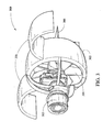
- Fig. 1 shows a perspective view of a ducted fan air vehicle 100 in accordance with a first embodiment.
- the air vehicle 100 includes a body portion 101 comprising a frame 102 to which a motor 103 is attached.
- the motor 103 drives an impeller 104 to provide propulsion for the air vehicle 100.
- a plurality of vanes 105 can be used in cooperation with the impelled air to provide steering capabilities for the body portion 101, such as by remote control or by a preprogrammed flight plan.
- the motor 103 may be powered by electrical energy, a gas-fueled engine or other appropriate means of generating mechanical energy. Control of the motor 103 may be exercised remotely or via pre-programmed instructions.
- the air vehicle 100 also includes one or more retractable wings 106, 107.
- the wing 106 is shown at three separate times.
- the wing 106 at a first time instant 108 is shown in a stowed or retracted configuration.
- the wing 106 is shown at an intermediate semi-deployed position, between a stowed, retracted configuration and a deployed configuration.
- the wing 106 is shown in a fully deployed position.
- the wing 106 will typically be in either a stowed configuration or a fully deployed configuration.
- the wings 106, 107 When in a retracted position, the wings 106, 107 may be positioned adjacent to the perimeter of the body 101. However, other retracted positions may provide the desired aerodynamic properties in light of the overall design of the vehicle 100, the body shape 101, and/or the shape of the wings 106, 107.
- One or more stopping means such as a mechanical stop 111 can be included in or on the body portion 101, or as part of the base of the wings 106, 107, to hold the wings 106, 107 open at a desired position, such as a predetermined angle relative to the body portion 101.
- a desired position such as a predetermined angle relative to the body portion 101.
- one or more retraction servos 112 may be included to retract the wings 106, 107 and/or to deploy the wings 106, 107.
- the retraction servos 112 may be any type of servo mechanism, or a device used to provide control of the position of the wings 106, 107.
- an electric servo motor is used to create mechanical force to move the wings 106, 107.
- other types of servos may be used as well, including, but not restricted to, mechanisms using hydraulic, pneumatic, or magnetic principles.
- Deployment of the wings 106, 107 is preferably only initiated by the servo 112, with the resultant air load providing force to fully open the wings.
- the servo 112 should be able to supply enough force to stow the wing(s) 106, 107 when the air vehicle 100 is in a hover. This force will be relatively low in a hover, since the wings 106, 107 will not be providing any significant lift to the air vehicle 100 during that time period.
- the wings 106, 107 are attached to the body 101 through a hinge or other mechanical pivoting mechanism 113 to allow the wings to rotate outward from the body 101 of the air vehicle 100.
- a first end of the wing 106 would be attached to a hinge 113 on the body 101, so that a second end of the wing can be extended outward and away from the body 101.
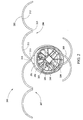
- Fig. 2 shows a perspective view of a ducted fan air vehicle 200 in accordance with a second embodiment.
- the air vehicle 200 includes a body portion 201 comprising a frame 202 to which a motor 203 is attached. Propulsion for the air vehicle 200 is provided by an impeller 204 which is driven by the motor 203. In conjunction with the impelled air, a plurality of vanes 205 can be used to provide steering capabilities for the body portion 201. Steering and other movements can be controlled remotely, or by a preprogrammed flight plan.
- the motor 203 may be powered by electrical energy, a gas-fueled engine or other appropriate means of generating mechanical energy. Remote control or preprogrammed instructions can be used to control the motor 203.
- the air vehicle 200 also includes one or more retractable wings 206, 207.
- the wing 206 is shown at three separate time instants. At a first time instant 208, the wing 206 is shown in a stowed or retracted configuration. At a second time instant 209, the wing 206 is shown at a semi-deployed position, between a stowed, retracted configuration and a deployed configuration. At a third time instant 210, the wing 206 is shown in a fully deployed position. Typically, the wing 206 will be in either a retracted configuration or a fully deployed configuration.
- the wings 206, 207 When in a retracted position, the wings 206, 207 may be positioned adjacent to the perimeter of the body 101. However, other retracted positions may provide the desired aerodynamic properties in light of the overall design of the vehicle 100, the body shape 101, and/or the shape of the wings 206, 207.
- Retractable wings 206, 207 for the air vehicle 200 differ from those of the air vehicle 100, in that each wing 206, 207 comprises two portions 211, 212 (e.g. portions having a radius of curvature approximating that of the body 202). This allows the deployed wings to have a greater surface area to provide improved lift, while maintaining similar hover characteristics while the wings are retracted to those of the air vehicle 100.
- Retractable wings 206, 207 are hinged, or otherwise movably connected, to one another. As shown in Fig. 2 , a hinge 213 can be included between the two portions 210, 211. While in forward flight, the aerodynamic load experienced by the wing portions 210, 211 can hold the wing portions 210, 211 in a deployed position. If the wings 206, 207 are sufficiently long such that they overlap while in a retracted position, the wings 206, 207 can be retracted and deployed sequentially.
- a mechanical stop 214 and retraction servo 215 can also be included in the air vehicle 200 to deploy the wings 206, 207, maintain the position of the wings 206, 207 with respect to the vehicle body 201, and retract the wings 206, 207 described with respect to the air vehicle 100 in Fig. 1 .
- Fig. 3 shows a perspective view of an example ducted fan air vehicle 300 in forward flight operation.
- the air vehicle 300 is shown in forward flight with the wings 301 fully deployed. As shown in Fig. 3 , the air vehicle 300 is moving to the left.
- the vehicle 300 includes a body section 302, an impeller 304 and a motor 305.
- the motor 305 drives the impeller 304 to generate a propulsive force.
- the motor is driven by electrical power or a gasoline-fueled engine, though any method of generating mechanical energy is appropriate.
- Control of the motor can be exercised by remote control, or through preprogrammed instructions.
- the propulsive force from the impelled air is directed by one or more vanes 306 to enable a variety of flight maneuvers. Control of the vanes 306 can also be exercised by remote control or through preprogrammed flight instructions.
- the wings 301 follow the general radius and curvature of the body 302 of the vehicle 300. When deployed, the wings 301 provide lift while the vehicle is moving forward, reducing the proportion of the force from the impeller 304 directed towards creating lift, and enabling more force from the impeller 304 to be directed towards forward flight.
- Fig. 4 shows a perspective view of the ducted fan air vehicle 300 in hover operation.
- the vehicle 300 is shown in hover with the wings 301 partially retracted.
- the wings 301 possess a profile 307 such that when the wings 301 are fully deployed and the vehicle 300 is in forward flight, the wings 301 provide lift.
- the wing profile 307 is only one appropriate profile, and persons of ordinary skill in the art will recognize that any wing profile that provides the desired aerodynamic properties is appropriate.
- the wings 301 themselves possess a shape and a curvature that generally conforms to the shape of the body 302 of the vehicle 300.
- the wings 301 may be have a semicircular shape.
- the wing shape depicted in Fig. 4 represents only one embodiment, and alternate wing shapes that provide the desired aerodynamic profile when in a retracted position may also be implemented.
- the wings 301 When hovering, the wings 301 will typically be in a retracted position, while the motor 305 drives the impeller 304 to lift the air vehicle 300 in a vertical fashion.
- the vanes 306 direct the impelled air to allow for a variety of flight maneuvers while hovering.
- the wings 301 are retracted during the hover operation to provide less resistance to the movement of the vehicle 300 and increase the stability of the hover.
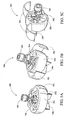
- Figs. 5A-C show perspective views of the ducted fan air vehicle 300 in operation transitioning from the hover operation to the forward flight operation.
- the vehicle 300 is in a hover position, with the wings 301 stowed in a retracted position.
- the motor 305 drives the impeller 304 to generate a propulsive force.
- a plurality of vanes 306 directs the force downward, creating lift and allowing the vehicle 300 to hover.
- the wings 301 are in the process of deploying.
- the vehicle 300 tips forward such that the propulsive force generated by the motor 305 and the impeller 304 provides lift for the vehicle 300 in conjunction with the lift provided by the wings 301.
- Deployment of the wings 301 is initiated by servo motors and is further aided by the air pressure experienced by the wings 301 during deployment.
- the wings 301 are fully deployed, and the vehicle 300 is in forward flight (e.g., moving to the right as shown in Fig. 5C ).
- the wings 301 provide lift for the vehicle 300, and the propulsive force generated by the motor 305 and impeller 304 primarily provides forward thrust.
- the direction of the vehicle 300 is controlled primarily by a plurality of vanes 306, which can change orientation to provide the desired change in direction of the vehicle 300.
- Fig. 6 shows a perspective view of the ducted fan air vehicle 300 in operation transitioning from forward flight operation to the hover operation
- the vehicle 300 is beginning the transition from forward flight to hover.
- the wings 301 are in a fully deployed position, and the body of the vehicle 300 is beginning to move into an upright position.
- the deployed wings 301 provide air braking to assist the vehicle 300 in transitioning from forward flight to hover.
- the vehicle 300 is in a hover and has commenced moving the wings 301 into a retracted position.
- the wings 301 are stowed in a retracted position, and the vehicle 300 is in a hover.
- the wings 301 will typically be stowed while the air vehicle 300 is in a hover, in order to improve stability characteristics (e.g. with regard to winds).
- the wings 301 will generally be deployed during forward flight (e.g. other than hover flight), in order to improve aerodynamic lift and efficiency.
- the wings 301 and other aspects of the design may be optimized for a particular speed of travel.
- Deployment and retraction of the wings 301 can be implemented automatically based on the airspeed of the vehicle 300.
- the wings 301 could automatically be deployed based on exceeding a given speed threshold based on where the wings 301 become effective. Retraction could occur when the vehicle 300 has slowed to where the wings 301 are no longer effective and where minimal retraction force would be required. These speeds could be determined empirically, for example.
- Design details for a retractable wing will depend on the characteristics of the air vehicle itself (e.g. size, shape, propulsive capabilities of the motor).
- the wings could be constructed using two layers glass with a carbon stiffener, and formed in a shape that approximates a profile of the air vehicle itself.
- the wings can be constructed from a wide variety of materials and formed in any shape that provides the desired aerodynamic properties.
- increased forward-flight efficiency provided by wings may not overcome the loss in efficiency due to the additional weight of the wings.
- the associated additional weight is avoided by using the deployable wing only when the operation of the air vehicle includes distance requirements. In such a case, the wing would be used as a temporary attachment to the vehicle, as called for by a desired operation.
- wings illustrated in Figs. 1-6 are generally round in shape, with a radius of curvature similar to that of the body of the air vehicle, this is an example implementation only. Other implementations, such as those utilizing a wing that straightens upon deployment, could alternatively be utilized.
- present embodiments may apply are not limited to the examples described above. While example applications for the air vehicles include operations in which the air vehicle glides or flies to its target location, the present application may provide benefits to other uses as well. Using the present embodiments, aerodynamic lift, and thus efficiency can be improved without significantly affecting hover stability in a wind.
Landscapes
- Engineering & Computer Science (AREA)
- Aviation & Aerospace Engineering (AREA)
- Mechanical Engineering (AREA)
- Remote Sensing (AREA)
- Chemical & Material Sciences (AREA)
- Combustion & Propulsion (AREA)
- Structures Of Non-Positive Displacement Pumps (AREA)
- Toys (AREA)
Abstract
Description
- The present patent application claims priority under 35 U.S.C. § 119(e) to
U.S. Provisional Patent Application Serial No. 60/915,542, filed on May 2, 2007 - The present application relates to ducted fan air vehicles, and more particularly, to a deployable wing system for such vehicles.
- A conventional ducted fan vehicle contains one or more motor-driven impellers to generate propulsive force and a means of directing that propulsive force, such as one or more vanes. By controlling the magnitude and direction of the propulsive force, ducted fan vehicles are capable of performing a wide variety of flight maneuvers, including forward flight and hovering. However, ducted fan vehicles have very limited aerodynamic lift in forward flight. The propulsive force provides most of the lift and also provides the thrust to propel the ducted fan vehicle forward. Reliance on the propulsive force to provide both lift and forward thrust limits the range and endurance of the vehicle, and tends to make the vehicle inefficient in forward flight.
- The present application is directed to ducted fan air vehicles and a means of improving forward-light efficiency without disrupting stability while in a hover. One or more retractable wings are deployed to provide aerodynamic lift in forward flight. Either automatically or in response to a command from an operator, the wing or wings can be retracted to return the ducted fan vehicle to an aerodynamic profile that is more stable in a hover. In one embodiment, a servo motor assists in the deployment and retraction of the wings. In another embodiment, the wings are comprised of more than one piece such that the wings follow the contour of the vehicle while in the stowed position. In yet another embodiment, the wings are detachable from the vehicle.
-
-
Fig. 1 shows a perspective view of a ducted fan air vehicle in accordance with a first embodiment. -
Fig. 2 shows a perspective view of a ducted fan air vehicle in accordance with a second embodiment. -
Fig. 3 shows a perspective view of the ducted fan air in forward flight operation. -
Fig. 4 shows a perspective view of the ducted fan air vehicle in a hover operation. -
Fig. 5 shows a sequence of perspective views of the ducted fan air vehicle transitioning from the hover operation to the forward flight operation. -
Fig. 6 shows a sequence of perspective views of the ducted fan air vehicle transitioning from the forward flight operation to the hover operation. - Many traditional aircraft utilize a fixed lifting surface to provide lift in forward flight. However, when a ducted fan vehicle hovers, the aerodynamic profile of the vehicle has a significant impact on the stability of the vehicle, especially when a wind is present. Thus while attaching a fixed lifting surface to the ducted fan vehicle may improve efficiency in forward flight, a fixed lifting surface typically has a detrimental affect on the hover stability of the vehicle in a wind.
-
Fig. 1 shows a perspective view of a ductedfan air vehicle 100 in accordance with a first embodiment. Theair vehicle 100 includes abody portion 101 comprising aframe 102 to which amotor 103 is attached. Themotor 103 drives animpeller 104 to provide propulsion for theair vehicle 100. A plurality ofvanes 105 can be used in cooperation with the impelled air to provide steering capabilities for thebody portion 101, such as by remote control or by a preprogrammed flight plan. Themotor 103 may be powered by electrical energy, a gas-fueled engine or other appropriate means of generating mechanical energy. Control of themotor 103 may be exercised remotely or via pre-programmed instructions. - The
air vehicle 100 also includes one or moreretractable wings Fig. 1 , twowings wing 106 is shown at three separate times. Thewing 106 at afirst time instant 108 is shown in a stowed or retracted configuration. At asecond time instant 109, thewing 106 is shown at an intermediate semi-deployed position, between a stowed, retracted configuration and a deployed configuration. Finally, at athird time instant 110, thewing 106 is shown in a fully deployed position. Thewing 106 will typically be in either a stowed configuration or a fully deployed configuration. When in a retracted position, thewings body 101. However, other retracted positions may provide the desired aerodynamic properties in light of the overall design of thevehicle 100, thebody shape 101, and/or the shape of thewings - One or more stopping means, such as a
mechanical stop 111 can be included in or on thebody portion 101, or as part of the base of thewings wings body portion 101. When thewings mechanical stop 111 by the aerodynamic forces experienced by thewings - In addition, one or
more retraction servos 112 may be included to retract thewings wings retraction servos 112 may be any type of servo mechanism, or a device used to provide control of the position of thewings wings - Deployment of the
wings servo 112, with the resultant air load providing force to fully open the wings. Theservo 112 should be able to supply enough force to stow the wing(s) 106, 107 when theair vehicle 100 is in a hover. This force will be relatively low in a hover, since thewings air vehicle 100 during that time period. - The
wings body 101 through a hinge or othermechanical pivoting mechanism 113 to allow the wings to rotate outward from thebody 101 of theair vehicle 100. For example, a first end of thewing 106 would be attached to ahinge 113 on thebody 101, so that a second end of the wing can be extended outward and away from thebody 101. -
Fig. 2 shows a perspective view of a ductedfan air vehicle 200 in accordance with a second embodiment. Theair vehicle 200 includes abody portion 201 comprising aframe 202 to which amotor 203 is attached. Propulsion for theair vehicle 200 is provided by animpeller 204 which is driven by themotor 203. In conjunction with the impelled air, a plurality ofvanes 205 can be used to provide steering capabilities for thebody portion 201. Steering and other movements can be controlled remotely, or by a preprogrammed flight plan. Themotor 203 may be powered by electrical energy, a gas-fueled engine or other appropriate means of generating mechanical energy. Remote control or preprogrammed instructions can be used to control themotor 203. - The
air vehicle 200 also includes one or moreretractable wings Fig. 2 , twowings wing 206 is shown at three separate time instants. At afirst time instant 208, thewing 206 is shown in a stowed or retracted configuration. At asecond time instant 209, thewing 206 is shown at a semi-deployed position, between a stowed, retracted configuration and a deployed configuration. At athird time instant 210, thewing 206 is shown in a fully deployed position. Typically, thewing 206 will be in either a retracted configuration or a fully deployed configuration. When in a retracted position, thewings body 101. However, other retracted positions may provide the desired aerodynamic properties in light of the overall design of thevehicle 100, thebody shape 101, and/or the shape of thewings -
Retractable wings air vehicle 200 differ from those of theair vehicle 100, in that eachwing portions 211, 212 (e.g. portions having a radius of curvature approximating that of the body 202). This allows the deployed wings to have a greater surface area to provide improved lift, while maintaining similar hover characteristics while the wings are retracted to those of theair vehicle 100. -
Retractable wings Fig. 2 , ahinge 213 can be included between the twoportions wing portions wing portions wings wings - A
mechanical stop 214 andretraction servo 215 can also be included in theair vehicle 200 to deploy thewings wings vehicle body 201, and retract thewings air vehicle 100 inFig. 1 . -
Fig. 3 shows a perspective view of an example ductedfan air vehicle 300 in forward flight operation. Theair vehicle 300 is shown in forward flight with thewings 301 fully deployed. As shown inFig. 3 , theair vehicle 300 is moving to the left. - The
vehicle 300 includes abody section 302, animpeller 304 and amotor 305. Themotor 305 drives theimpeller 304 to generate a propulsive force. Typically, the motor is driven by electrical power or a gasoline-fueled engine, though any method of generating mechanical energy is appropriate. Control of the motor can be exercised by remote control, or through preprogrammed instructions. The propulsive force from the impelled air is directed by one ormore vanes 306 to enable a variety of flight maneuvers. Control of thevanes 306 can also be exercised by remote control or through preprogrammed flight instructions. - The
wings 301 follow the general radius and curvature of thebody 302 of thevehicle 300. When deployed, thewings 301 provide lift while the vehicle is moving forward, reducing the proportion of the force from theimpeller 304 directed towards creating lift, and enabling more force from theimpeller 304 to be directed towards forward flight. -
Fig. 4 shows a perspective view of the ductedfan air vehicle 300 in hover operation. Thevehicle 300 is shown in hover with thewings 301 partially retracted. - The
wings 301 possess aprofile 307 such that when thewings 301 are fully deployed and thevehicle 300 is in forward flight, thewings 301 provide lift. Thewing profile 307 is only one appropriate profile, and persons of ordinary skill in the art will recognize that any wing profile that provides the desired aerodynamic properties is appropriate. Thewings 301 themselves possess a shape and a curvature that generally conforms to the shape of thebody 302 of thevehicle 300. For example, as shown inFig. 4 , thewings 301 may be have a semicircular shape. However, the wing shape depicted inFig. 4 represents only one embodiment, and alternate wing shapes that provide the desired aerodynamic profile when in a retracted position may also be implemented. - When hovering, the
wings 301 will typically be in a retracted position, while themotor 305 drives theimpeller 304 to lift theair vehicle 300 in a vertical fashion. Thevanes 306 direct the impelled air to allow for a variety of flight maneuvers while hovering. Thewings 301 are retracted during the hover operation to provide less resistance to the movement of thevehicle 300 and increase the stability of the hover. -
Figs. 5A-C show perspective views of the ductedfan air vehicle 300 in operation transitioning from the hover operation to the forward flight operation. - At a first time shown in
Fig. 5A , thevehicle 300 is in a hover position, with thewings 301 stowed in a retracted position. Themotor 305 drives theimpeller 304 to generate a propulsive force. A plurality ofvanes 306 directs the force downward, creating lift and allowing thevehicle 300 to hover. - At a second time shown in
Fig. 5B , thewings 301 are in the process of deploying. During deployment of thewings 301, thevehicle 300 tips forward such that the propulsive force generated by themotor 305 and theimpeller 304 provides lift for thevehicle 300 in conjunction with the lift provided by thewings 301. Deployment of thewings 301 is initiated by servo motors and is further aided by the air pressure experienced by thewings 301 during deployment. - At a third time shown in
Fig. 5C , thewings 301 are fully deployed, and thevehicle 300 is in forward flight (e.g., moving to the right as shown inFig. 5C ). In this configuration, thewings 301 provide lift for thevehicle 300, and the propulsive force generated by themotor 305 andimpeller 304 primarily provides forward thrust. The direction of thevehicle 300 is controlled primarily by a plurality ofvanes 306, which can change orientation to provide the desired change in direction of thevehicle 300. -
Fig. 6 shows a perspective view of the ductedfan air vehicle 300 in operation transitioning from forward flight operation to the hover operation - At a first time as shown in
Fig. 6A , thevehicle 300 is beginning the transition from forward flight to hover. Thewings 301 are in a fully deployed position, and the body of thevehicle 300 is beginning to move into an upright position. In this configuration, the deployedwings 301 provide air braking to assist thevehicle 300 in transitioning from forward flight to hover. - At a second time as shown in
Fig. 6B , thevehicle 300 is in a hover and has commenced moving thewings 301 into a retracted position. In this configuration, there is little or no air load on thewings 301 and servo motors can be used to move thewings 301 into a retracted position. - At a third time shown in
Fig. 6C , thewings 301 are stowed in a retracted position, and thevehicle 300 is in a hover. - In general, the
wings 301 will typically be stowed while theair vehicle 300 is in a hover, in order to improve stability characteristics (e.g. with regard to winds). Thewings 301 will generally be deployed during forward flight (e.g. other than hover flight), in order to improve aerodynamic lift and efficiency. Thewings 301 and other aspects of the design may be optimized for a particular speed of travel. - Deployment and retraction of the
wings 301 can be implemented automatically based on the airspeed of thevehicle 300. Thewings 301 could automatically be deployed based on exceeding a given speed threshold based on where thewings 301 become effective. Retraction could occur when thevehicle 300 has slowed to where thewings 301 are no longer effective and where minimal retraction force would be required. These speeds could be determined empirically, for example. - Design details for a retractable wing will depend on the characteristics of the air vehicle itself (e.g. size, shape, propulsive capabilities of the motor). For example, the wings could be constructed using two layers glass with a carbon stiffener, and formed in a shape that approximates a profile of the air vehicle itself. However, persons of ordinary skill in the art will recognize that the wings can be constructed from a wide variety of materials and formed in any shape that provides the desired aerodynamic properties.
- In some situations, such as when operation of the air vehicle includes minimal non-hover flight, increased forward-flight efficiency provided by wings may not overcome the loss in efficiency due to the additional weight of the wings. In an example implementation, the associated additional weight is avoided by using the deployable wing only when the operation of the air vehicle includes distance requirements. In such a case, the wing would be used as a temporary attachment to the vehicle, as called for by a desired operation.
- While the wings illustrated in
Figs. 1-6 are generally round in shape, with a radius of curvature similar to that of the body of the air vehicle, this is an example implementation only. Other implementations, such as those utilizing a wing that straightens upon deployment, could alternatively be utilized. - The applications to which present embodiments may apply are not limited to the examples described above. While example applications for the air vehicles include operations in which the air vehicle glides or flies to its target location, the present application may provide benefits to other uses as well. Using the present embodiments, aerodynamic lift, and thus efficiency can be improved without significantly affecting hover stability in a wind.
- While examples have been described in conjunction with present embodiments of the application, persons of skill in the art will appreciate that variations may be made without departure from the scope and spirit of the application. The true scope and spirit of the application is defined by the appended claims, which may be interpreted in light of the foregoing.
Claims (10)
- A method for operating a ducted fan air vehicle having at least one retractable wing, comprising:deploying the retractable wing for a forward-flight operation of the ducted fan air vehicle; andstowing the retractable wing in a retracted position for a hover operation of the ducted fan air vehicle.
- The method of claim 1 wherein the retractable wing conforms with a profile of the ducted fan air vehicle while in the retracted position.
- The method of claim 1 further comprising:automatically deploying the retractable wing when the ducted fan air vehicle meets or exceeds a pre-selected speed; andautomatically retracting the retractable wing when the ducted fan air vehicle slows to or below a pre-selected speed.
- The method of claim 1 wherein the ducted fan air vehicle includes two retractable wings, and the method further comprises:deploying the two retractable wings for the forward-flight operation of the ducted fan air vehicle; andstowing each of the two retractable wings in retracted positions for the hover operation of the ducted fan air vehicle.
- The method of claim 1 wherein deploying the retractable wing for the forward-flight operation of the ducted fan air vehicle comprises extending the retractable wing outward from a body of the ducted fan air vehicle.
- The method of claim 1 wherein stowing the retractable wing in the retracted position for the hover operation of the ducted fan air vehicle comprises retracting the retractable wing inward to a body of the ducted fan air vehicle.
- The method of claim 1 wherein the ducted fan air vehicle includes a body including a motor and impeller controlled by the motor, and wherein the retractable wing has a first end and a second end, wherein the first end is connected to the body, and wherein in the retracted position the retractable wing conforms with a profile of the ducted fan air vehicle and in a deployed position the second end is extended outward from the body.
- The method of claim 7 wherein the retractable wing is detachable from the ducted fan air vehicle.
- The method of claim 7 wherein the first end of the retractable wing is connected to the body via a hinge.
- The method of claim 7 wherein in the retracted position the retractable wing is positioned adjacent a portion of a perimeter of the body.
Applications Claiming Priority (2)
| Application Number | Priority Date | Filing Date | Title |
|---|---|---|---|
| US91554207P | 2007-05-02 | 2007-05-02 | |
| US11/947,585 US7681832B2 (en) | 2007-05-02 | 2007-11-29 | Ducted fan air vehicle with deployable wings |
Publications (2)
| Publication Number | Publication Date |
|---|---|
| EP1988014A2 true EP1988014A2 (en) | 2008-11-05 |
| EP1988014A3 EP1988014A3 (en) | 2010-12-08 |
Family
ID=39540404
Family Applications (1)
| Application Number | Title | Priority Date | Filing Date |
|---|---|---|---|
| EP20080155550 Withdrawn EP1988014A3 (en) | 2007-05-02 | 2008-05-01 | Ducted fan air vehicle with deployable wings |
Country Status (2)
| Country | Link |
|---|---|
| US (1) | US7681832B2 (en) |
| EP (1) | EP1988014A3 (en) |
Cited By (4)
| Publication number | Priority date | Publication date | Assignee | Title |
|---|---|---|---|---|
| WO2016003530A3 (en) * | 2014-05-08 | 2016-03-10 | Northrop Grumman Systems Corporation | Vertical takeoff and landing (vtol) unmanned aerial vehicle (uav) |
| WO2016193690A1 (en) * | 2015-06-01 | 2016-12-08 | Imperial Innovations Limited | Aerial devices capable of controlled flight |
| US10569856B2 (en) | 2014-08-04 | 2020-02-25 | Alibi Akhmejanov | Aerodynamic device |
| US10773817B1 (en) | 2018-03-08 | 2020-09-15 | Northrop Grumman Systems Corporation | Bi-directional flow ram air system for an aircraft |
Families Citing this family (19)
| Publication number | Priority date | Publication date | Assignee | Title |
|---|---|---|---|---|
| JP4899069B2 (en) * | 2009-03-05 | 2012-03-21 | 防衛省技術研究本部長 | Spherical airplane |
| WO2010074595A1 (en) * | 2009-06-01 | 2010-07-01 | Afanasyev Sergey Nikolaevich | Aircraft |
| US8376263B2 (en) | 2010-08-27 | 2013-02-19 | Rolls-Royce Corporation | Roadable aircraft |
| US9004393B2 (en) | 2010-10-24 | 2015-04-14 | University Of Kansas | Supersonic hovering air vehicle |
| KR101150855B1 (en) | 2010-12-22 | 2012-06-13 | 한국생산기술연구원 | Flight control structure of duct type flight robot |
| USD656162S1 (en) | 2011-08-23 | 2012-03-20 | Alfred Wiik | Combination snow plow and shovel |
| US9284962B2 (en) * | 2012-08-24 | 2016-03-15 | Zee.Aero Inc. | Variable geometry lift fan mechanism |
| JP6213713B2 (en) | 2013-05-16 | 2017-10-18 | 株式会社Ihi | Vertical take-off and landing aircraft |
| CN104443373A (en) * | 2013-09-16 | 2015-03-25 | 阮明振 | Wind wheel type helicopter |
| US9540103B2 (en) | 2014-06-24 | 2017-01-10 | Kitty Hawk Corporation | Passive deployment mechanism for lift fan |
| US10107196B2 (en) | 2014-08-08 | 2018-10-23 | Thomas International, Inc. | Adjustable size inlet system |
| WO2017044388A1 (en) * | 2015-09-11 | 2017-03-16 | Northrop Grumman Systems Corporation | Vertical takeoff and landing (vtol) unmanned aerial vehicle (uav) |
| RU2691677C2 (en) * | 2017-08-24 | 2019-06-17 | Игорь Викторович Лентов | Bearing ring propeller |
| US11767097B2 (en) | 2018-04-17 | 2023-09-26 | University Of Kansas | Acoustic noise suppressing ducted fan propulsor mounting arrangement and treatments |
| US11851178B2 (en) * | 2020-02-14 | 2023-12-26 | The Aerospace Corporation | Long range endurance aero platform system |
| CN112478152B (en) * | 2020-12-14 | 2022-11-01 | 江西洪都航空工业股份有限公司 | Deployable single duct aircraft |
| CN112829933A (en) * | 2021-02-23 | 2021-05-25 | 姜铁华 | Aircraft with deployable duct wings |
| CN113665803B (en) * | 2021-09-02 | 2022-04-08 | 涵涡智航科技(玉溪)有限公司 | an aircraft |
| EP4568895A1 (en) * | 2022-08-09 | 2025-06-18 | Pete Bitar | Compact and lightweight drone delivery device called an arcspear electric jet drone system having an electric ducted air propulsion system and being relatively difficult to track in flight |
Citations (7)
| Publication number | Priority date | Publication date | Assignee | Title |
|---|---|---|---|---|
| US1448166A (en) | 1918-05-15 | 1923-03-13 | Edw Fay Wilson | Projectile |
| US3493195A (en) | 1967-12-22 | 1970-02-03 | Frank O Nelson | Propulsion unit for aircraft and other vehicles |
| FR2651139A2 (en) | 1988-02-24 | 1991-03-01 | Koehl Jean Marie | Fire-fighting method and remotely guided airborne means relating thereto |
| US5074493A (en) | 1990-12-21 | 1991-12-24 | The United States Of America As Represented By The Secretary Of The Navy | Wing-extendible gliding store |
| EP1114772A1 (en) | 1999-12-29 | 2001-07-11 | Gkn Westland Helicopters Limited | VTOL aircraft with variable wing sweep |
| US20060113426A1 (en) | 2002-08-05 | 2006-06-01 | Raphael Yoeli | Vtol vehicles |
| US20060192047A1 (en) | 2005-02-25 | 2006-08-31 | Honeywell International Inc. | Double ducted hovering air-vehicle |
Family Cites Families (60)
| Publication number | Priority date | Publication date | Assignee | Title |
|---|---|---|---|---|
| US3606208A (en) * | 1968-12-11 | 1971-09-20 | Steven Postelson Apostolescu | Flying platform-automobile boat and air suspension car combination |
| GB8404752D0 (en) | 1984-02-23 | 1984-03-28 | Ici Plc | Vehicles |
| USH685H (en) * | 1988-06-20 | 1989-10-03 | The United States Of America As Represented By The Secretary Of The Army | Deployable fin configuration for free flight control of cylindrical bodies |
| US5152478A (en) | 1990-05-18 | 1992-10-06 | United Technologies Corporation | Unmanned flight vehicle including counter rotating rotors positioned within a toroidal shroud and operable to provide all required vehicle flight controls |
| US5150857A (en) | 1991-08-13 | 1992-09-29 | United Technologies Corporation | Shroud geometry for unmanned aerial vehicles |
| US5295643A (en) | 1992-12-28 | 1994-03-22 | Hughes Missile Systems Company | Unmanned vertical take-off and landing, horizontal cruise, air vehicle |
| US5575438A (en) | 1994-05-09 | 1996-11-19 | United Technologies Corporation | Unmanned VTOL ground surveillance vehicle |
| US5695153A (en) | 1995-11-16 | 1997-12-09 | Northrop Grumman Corporation | Launcher system for an unmanned aerial vehicle |
| AU2251500A (en) | 1998-08-27 | 2000-04-03 | Nicolae Bostan | Gyrostabilized self propelled aircraft |
| US6073882A (en) | 1998-09-21 | 2000-06-13 | Zieger; N. Henning | Flying vehicle with retractable wing assembly |
| WO2000040464A2 (en) | 1998-12-11 | 2000-07-13 | Moller International, Inc. | Stabilizing control apparatus for robotic or remotely controlled flying platform |
| US6422508B1 (en) | 2000-04-05 | 2002-07-23 | Galileo Group, Inc. | System for robotic control of imaging data having a steerable gimbal mounted spectral sensor and methods |
| IL138695A (en) | 2000-09-26 | 2004-08-31 | Rafael Armament Dev Authority | Unmanned mobile device |
| US6622090B2 (en) | 2000-09-26 | 2003-09-16 | American Gnc Corporation | Enhanced inertial measurement unit/global positioning system mapping and navigation process |
| US6883748B2 (en) * | 2001-06-04 | 2005-04-26 | Rafi Yoeli | Vehicles particularly useful as VTOL vehicles |
| WO2003004353A2 (en) | 2001-07-06 | 2003-01-16 | The Charles Stark Draper Laboratory, Inc. | Vertical takeoff and landing aerial vehicle |
| US6847865B2 (en) | 2001-09-27 | 2005-01-25 | Ernest A. Carroll | Miniature, unmanned aircraft with onboard stabilization and automated ground control of flight path |
| US6721646B2 (en) | 2001-09-27 | 2004-04-13 | Ernest A. Carroll | Unmanned aircraft with automatic fuel-to-air mixture adjustment |
| US6665594B1 (en) | 2001-12-13 | 2003-12-16 | The United States Of America As Represented By The Secretary Of The Navy | Plug and play modular mission payloads |
| US20040094662A1 (en) | 2002-01-07 | 2004-05-20 | Sanders John K. | Vertical tale-off landing hovercraft |
| US7032861B2 (en) | 2002-01-07 | 2006-04-25 | Sanders Jr John K | Quiet vertical takeoff and landing aircraft using ducted, magnetic induction air-impeller rotors |
| US6502787B1 (en) | 2002-02-22 | 2003-01-07 | Micro Autonomous Systems Llc | Convertible vertical take-off and landing miniature aerial vehicle |
| US6575402B1 (en) | 2002-04-17 | 2003-06-10 | Sikorsky Aircraft Corporation | Cooling system for a hybrid aircraft |
| US6694228B2 (en) | 2002-05-09 | 2004-02-17 | Sikorsky Aircraft Corporation | Control system for remotely operated vehicles for operational payload employment |
| CN1662419A (en) | 2002-06-28 | 2005-08-31 | Vtol技术有限公司 | Ducted air power plant |
| AU2003264929A1 (en) | 2002-09-23 | 2004-04-08 | Stefan Reich | Measuring and stabilising system for machine-controllable vehicles |
| US6873886B1 (en) | 2002-11-27 | 2005-03-29 | The United States Of America As Represented By The Secretary Of The Navy | Modular mission payload control software |
| US7000883B2 (en) | 2003-01-17 | 2006-02-21 | The Insitu Group, Inc. | Method and apparatus for stabilizing payloads, including airborne cameras |
| US6712312B1 (en) | 2003-01-31 | 2004-03-30 | The United States Of America As Represented By The Secretary Of The Navy | Reconnaissance using unmanned surface vehicles and unmanned micro-aerial vehicles |
| SE0300871D0 (en) | 2003-03-27 | 2003-03-27 | Saab Ab | Waypoint navigation |
| ITTO20030588A1 (en) | 2003-07-30 | 2005-01-31 | Fiat Ricerche | FLYING CAR. |
| US6813559B1 (en) | 2003-10-23 | 2004-11-02 | International Business Machines Corporation | Orbiting a waypoint |
| US7231294B2 (en) | 2003-10-23 | 2007-06-12 | International Business Machines Corporation | Navigating a UAV |
| US7299130B2 (en) | 2003-12-12 | 2007-11-20 | Advanced Ceramic Research, Inc. | Unmanned vehicle |
| US7289906B2 (en) | 2004-04-05 | 2007-10-30 | Oregon Health & Science University | Navigation system applications of sigma-point Kalman filters for nonlinear estimation and sensor fusion |
| US7262395B2 (en) | 2004-05-19 | 2007-08-28 | Derek Bilyk | Expendable sonobuoy flight kit with aerodynamically assisted sonobuoy separation |
| EP1612632B1 (en) | 2004-07-03 | 2009-01-07 | Saab Ab | A system and method for in-flight control of an aerial vehicle |
| US7228227B2 (en) | 2004-07-07 | 2007-06-05 | The Boeing Company | Bezier curve flightpath guidance using moving waypoints |
| US7302316B2 (en) | 2004-09-14 | 2007-11-27 | Brigham Young University | Programmable autopilot system for autonomous flight of unmanned aerial vehicles |
| US7559191B2 (en) | 2004-09-17 | 2009-07-14 | Aurora Flight Sciences Corporation | Ducted spinner for engine cooling |
| DE202004017679U1 (en) | 2004-11-15 | 2006-03-23 | Dolmar Gmbh | Starting brake for a hedge trimmer |
| US7512462B2 (en) | 2004-11-16 | 2009-03-31 | Northrop Grumman Corporation | Automatic contingency generator |
| US20060287824A1 (en) | 2005-01-29 | 2006-12-21 | American Gnc Corporation | Interruption free navigator |
| US7520466B2 (en) | 2005-03-17 | 2009-04-21 | Nicolae Bostan | Gyro-stabilized air vehicle |
| US7748486B2 (en) | 2005-06-09 | 2010-07-06 | Honeywell International, Inc. | Landing gear for a hovercraft |
| US7962252B2 (en) | 2005-06-20 | 2011-06-14 | The United States Of America As Represented By The Administrator Of The National Aeronautics And Space Administration | Self-contained avionics sensing and flight control system for small unmanned aerial vehicle |
| US20070228214A1 (en) | 2005-09-26 | 2007-10-04 | Honeywell International Inc. | Autonomous launch pad for micro air vehicles |
| AU2005338333A1 (en) | 2005-11-15 | 2007-05-24 | Bell Helicopter Textron, Inc. | Control system for automatic circle flight |
| FR2894368B1 (en) | 2005-12-07 | 2008-01-25 | Thales Sa | DEVICE AND METHOD FOR AUTOMATED CONSTRUCTION OF EMERGENCY TRACK FOR AIRCRAFT |
| US7469725B2 (en) | 2006-02-22 | 2008-12-30 | Honeywell International Inc. | Method and apparatus for accurately delivering a predetermined amount of fuel to a vehicle |
| US7510142B2 (en) | 2006-02-24 | 2009-03-31 | Stealth Robotics | Aerial robot |
| US7841563B2 (en) | 2006-03-27 | 2010-11-30 | Honeywell International Inc. | Ducted fan air data system |
| US20070244608A1 (en) | 2006-04-13 | 2007-10-18 | Honeywell International Inc. | Ground control station for UAV |
| US20070262195A1 (en) | 2006-05-11 | 2007-11-15 | Robert Bulaga | UAV With Control and Stability System |
| US7720577B2 (en) | 2006-05-17 | 2010-05-18 | The Boeing Company | Methods and systems for data link front end filters for sporadic updates |
| US7702460B2 (en) | 2006-06-17 | 2010-04-20 | Northrop Grumman Guidance And Electronics Company, Inc. | Estimate of relative position between navigation units |
| US7967255B2 (en) | 2006-07-27 | 2011-06-28 | Raytheon Company | Autonomous space flight system and planetary lander for executing a discrete landing sequence to remove unknown navigation error, perform hazard avoidance and relocate the lander and method |
| US7840352B2 (en) | 2006-09-05 | 2010-11-23 | Honeywell International Inc. | Method and system for autonomous vehicle navigation |
| US7693617B2 (en) | 2006-09-19 | 2010-04-06 | The Boeing Company | Aircraft precision approach control |
| US20080078865A1 (en) | 2006-09-21 | 2008-04-03 | Honeywell International Inc. | Unmanned Sensor Placement In A Cluttered Terrain |
-
2007
- 2007-11-29 US US11/947,585 patent/US7681832B2/en not_active Expired - Fee Related
-
2008
- 2008-05-01 EP EP20080155550 patent/EP1988014A3/en not_active Withdrawn
Patent Citations (7)
| Publication number | Priority date | Publication date | Assignee | Title |
|---|---|---|---|---|
| US1448166A (en) | 1918-05-15 | 1923-03-13 | Edw Fay Wilson | Projectile |
| US3493195A (en) | 1967-12-22 | 1970-02-03 | Frank O Nelson | Propulsion unit for aircraft and other vehicles |
| FR2651139A2 (en) | 1988-02-24 | 1991-03-01 | Koehl Jean Marie | Fire-fighting method and remotely guided airborne means relating thereto |
| US5074493A (en) | 1990-12-21 | 1991-12-24 | The United States Of America As Represented By The Secretary Of The Navy | Wing-extendible gliding store |
| EP1114772A1 (en) | 1999-12-29 | 2001-07-11 | Gkn Westland Helicopters Limited | VTOL aircraft with variable wing sweep |
| US20060113426A1 (en) | 2002-08-05 | 2006-06-01 | Raphael Yoeli | Vtol vehicles |
| US20060192047A1 (en) | 2005-02-25 | 2006-08-31 | Honeywell International Inc. | Double ducted hovering air-vehicle |
Cited By (7)
| Publication number | Priority date | Publication date | Assignee | Title |
|---|---|---|---|---|
| WO2016003530A3 (en) * | 2014-05-08 | 2016-03-10 | Northrop Grumman Systems Corporation | Vertical takeoff and landing (vtol) unmanned aerial vehicle (uav) |
| US10054958B2 (en) | 2014-05-08 | 2018-08-21 | Northrop Grumman Systems Corporation | Vertical takeoff and landing (VTOL) unmanned aerial vehicle (UAV) |
| US10481616B2 (en) | 2014-05-08 | 2019-11-19 | Northrop Grumman Systems Corporation | Vertical takeoff and landing (VTOL) unmanned aerial vehicle (UAV) |
| US10569856B2 (en) | 2014-08-04 | 2020-02-25 | Alibi Akhmejanov | Aerodynamic device |
| WO2016193690A1 (en) * | 2015-06-01 | 2016-12-08 | Imperial Innovations Limited | Aerial devices capable of controlled flight |
| US10875641B2 (en) | 2015-06-01 | 2020-12-29 | Imperial College Of Science, Technology And Medicine | Aerial devices capable of controlled flight |
| US10773817B1 (en) | 2018-03-08 | 2020-09-15 | Northrop Grumman Systems Corporation | Bi-directional flow ram air system for an aircraft |
Also Published As
| Publication number | Publication date |
|---|---|
| EP1988014A3 (en) | 2010-12-08 |
| US7681832B2 (en) | 2010-03-23 |
| US20080272226A1 (en) | 2008-11-06 |
Similar Documents
| Publication | Publication Date | Title |
|---|---|---|
| US7681832B2 (en) | Ducted fan air vehicle with deployable wings | |
| EP3464061B1 (en) | Propeller-hub assembly with folding blades for vtol aircraft | |
| CN103079955B (en) | private plane | |
| CA2673642C (en) | Dual rotor vertical takeoff and landing rotorcraft | |
| JP5676824B2 (en) | Private aircraft | |
| US8523103B2 (en) | Retractable lifting blades for aircraft | |
| JP2020514185A (en) | Folded wing multi-rotor | |
| CA2682372C (en) | Aircraft with aerodynamic lift generating device | |
| EP2917101B1 (en) | An airplane wing, an airplane and a flap system | |
| US6705568B2 (en) | Variable area wing aircraft and method | |
| CN110683045A (en) | Aircraft with a flight control device | |
| US11858629B2 (en) | Sliding panel for download alleviation on high-speed VTOL aircraft | |
| CN110395388B (en) | Edge driving type fan, double-state switching mechanism, wing and vertical take-off and landing aircraft | |
| JP2006514594A (en) | Winged spacecraft | |
| KR20250138201A (en) | Blade pitch coupled to propulsion system tilt | |
| WO1990001002A1 (en) | Helicopter rotor blades | |
| US7004427B2 (en) | Retractable lifting blades for aircraft | |
| GB2504369A (en) | Aircraft wing with reciprocating outer aerofoil sections | |
| US6405980B1 (en) | Control system for rotor aircraft | |
| CN108202568A (en) | flying car | |
| US20220111972A1 (en) | Propulsion system for an aircraft | |
| CN114633878B (en) | propeller mechanism of aerial mobility vehicle | |
| CN110104163B (en) | A kind of drone with drooping wings | |
| JP2010280252A (en) | Vertical tail of aircraft | |
| EP3589542A1 (en) | Kite systems |
Legal Events
| Date | Code | Title | Description |
|---|---|---|---|
| PUAI | Public reference made under article 153(3) epc to a published international application that has entered the european phase |
Free format text: ORIGINAL CODE: 0009012 |
|
| 17P | Request for examination filed |
Effective date: 20080501 |
|
| AK | Designated contracting states |
Kind code of ref document: A2 Designated state(s): AT BE BG CH CY CZ DE DK EE ES FI FR GB GR HR HU IE IS IT LI LT LU LV MC MT NL NO PL PT RO SE SI SK TR |
|
| AX | Request for extension of the european patent |
Extension state: AL BA MK RS |
|
| PUAL | Search report despatched |
Free format text: ORIGINAL CODE: 0009013 |
|
| AK | Designated contracting states |
Kind code of ref document: A3 Designated state(s): AT BE BG CH CY CZ DE DK EE ES FI FR GB GR HR HU IE IS IT LI LT LU LV MC MT NL NO PL PT RO SE SI SK TR |
|
| AX | Request for extension of the european patent |
Extension state: AL BA MK RS |
|
| 17Q | First examination report despatched |
Effective date: 20101117 |
|
| AKX | Designation fees paid |
Designated state(s): DE FR GB |
|
| GRAP | Despatch of communication of intention to grant a patent |
Free format text: ORIGINAL CODE: EPIDOSNIGR1 |
|
| INTG | Intention to grant announced |
Effective date: 20150522 |
|
| RAP1 | Party data changed (applicant data changed or rights of an application transferred) |
Owner name: HONEYWELL INTERNATIONAL INC. |
|
| STAA | Information on the status of an ep patent application or granted ep patent |
Free format text: STATUS: THE APPLICATION IS DEEMED TO BE WITHDRAWN |
|
| 18D | Application deemed to be withdrawn |
Effective date: 20151002 |