EP1987981A1 - Vehicle seat - Google Patents
Vehicle seat Download PDFInfo
- Publication number
- EP1987981A1 EP1987981A1 EP07713886A EP07713886A EP1987981A1 EP 1987981 A1 EP1987981 A1 EP 1987981A1 EP 07713886 A EP07713886 A EP 07713886A EP 07713886 A EP07713886 A EP 07713886A EP 1987981 A1 EP1987981 A1 EP 1987981A1
- Authority
- EP
- European Patent Office
- Prior art keywords
- seat
- bottom cushion
- support frame
- anchor
- pretensioner
- Prior art date
- Legal status (The legal status is an assumption and is not a legal conclusion. Google has not performed a legal analysis and makes no representation as to the accuracy of the status listed.)
- Granted
Links
Images



Classifications
-
- B—PERFORMING OPERATIONS; TRANSPORTING
- B60—VEHICLES IN GENERAL
- B60R—VEHICLES, VEHICLE FITTINGS, OR VEHICLE PARTS, NOT OTHERWISE PROVIDED FOR
- B60R22/00—Safety belts or body harnesses in vehicles
- B60R22/18—Anchoring devices
- B60R22/26—Anchoring devices secured to the seat
-
- B—PERFORMING OPERATIONS; TRANSPORTING
- B60—VEHICLES IN GENERAL
- B60N—SEATS SPECIALLY ADAPTED FOR VEHICLES; VEHICLE PASSENGER ACCOMMODATION NOT OTHERWISE PROVIDED FOR
- B60N2/00—Seats specially adapted for vehicles; Arrangement or mounting of seats in vehicles
- B60N2/24—Seats specially adapted for vehicles; Arrangement or mounting of seats in vehicles for particular purposes or particular vehicles
- B60N2/42—Seats specially adapted for vehicles; Arrangement or mounting of seats in vehicles for particular purposes or particular vehicles the seat constructed to protect the occupant from the effect of abnormal g-forces, e.g. crash or safety seats
- B60N2/4207—Seats specially adapted for vehicles; Arrangement or mounting of seats in vehicles for particular purposes or particular vehicles the seat constructed to protect the occupant from the effect of abnormal g-forces, e.g. crash or safety seats characterised by the direction of the g-forces
- B60N2/4214—Seats specially adapted for vehicles; Arrangement or mounting of seats in vehicles for particular purposes or particular vehicles the seat constructed to protect the occupant from the effect of abnormal g-forces, e.g. crash or safety seats characterised by the direction of the g-forces longitudinal
- B60N2/4221—Seats specially adapted for vehicles; Arrangement or mounting of seats in vehicles for particular purposes or particular vehicles the seat constructed to protect the occupant from the effect of abnormal g-forces, e.g. crash or safety seats characterised by the direction of the g-forces longitudinal due to impact coming from the front
-
- B—PERFORMING OPERATIONS; TRANSPORTING
- B60—VEHICLES IN GENERAL
- B60N—SEATS SPECIALLY ADAPTED FOR VEHICLES; VEHICLE PASSENGER ACCOMMODATION NOT OTHERWISE PROVIDED FOR
- B60N2/00—Seats specially adapted for vehicles; Arrangement or mounting of seats in vehicles
- B60N2/24—Seats specially adapted for vehicles; Arrangement or mounting of seats in vehicles for particular purposes or particular vehicles
- B60N2/42—Seats specially adapted for vehicles; Arrangement or mounting of seats in vehicles for particular purposes or particular vehicles the seat constructed to protect the occupant from the effect of abnormal g-forces, e.g. crash or safety seats
- B60N2/427—Seats or parts thereof displaced during a crash
- B60N2/42727—Seats or parts thereof displaced during a crash involving substantially rigid displacement
- B60N2/42754—Seats or parts thereof displaced during a crash involving substantially rigid displacement of the cushion
- B60N2/42763—Seats or parts thereof displaced during a crash involving substantially rigid displacement of the cushion with anti-submarining systems
-
- B—PERFORMING OPERATIONS; TRANSPORTING
- B60—VEHICLES IN GENERAL
- B60N—SEATS SPECIALLY ADAPTED FOR VEHICLES; VEHICLE PASSENGER ACCOMMODATION NOT OTHERWISE PROVIDED FOR
- B60N2/00—Seats specially adapted for vehicles; Arrangement or mounting of seats in vehicles
- B60N2/24—Seats specially adapted for vehicles; Arrangement or mounting of seats in vehicles for particular purposes or particular vehicles
- B60N2/42—Seats specially adapted for vehicles; Arrangement or mounting of seats in vehicles for particular purposes or particular vehicles the seat constructed to protect the occupant from the effect of abnormal g-forces, e.g. crash or safety seats
- B60N2/427—Seats or parts thereof displaced during a crash
- B60N2/42772—Seats or parts thereof displaced during a crash characterised by the triggering system
- B60N2/4279—Seats or parts thereof displaced during a crash characterised by the triggering system electric or electronic triggering
-
- B—PERFORMING OPERATIONS; TRANSPORTING
- B60—VEHICLES IN GENERAL
- B60R—VEHICLES, VEHICLE FITTINGS, OR VEHICLE PARTS, NOT OTHERWISE PROVIDED FOR
- B60R22/00—Safety belts or body harnesses in vehicles
- B60R22/18—Anchoring devices
- B60R22/195—Anchoring devices with means to tension the belt in an emergency, e.g. means of the through-anchor or splitted reel type
- B60R22/1952—Transmission of tensioning power by cable; Return motion locking means therefor
Definitions
- the present invention relates to a vehicle seat for effectively protecting a vehicle seat occupant when an unpreferable external force acts on a vehicle body and abruptly moves the vehicle seat occupant forward, and more particularly to a vehicle seat for moving a bottom cushion rearward in quick response to generation of an unpreferable external force.
- Patent Document 1 discloses a conventional technique for quickly moving a vehicle seat (including a seat back and a seat bottom) rearward when an unpreferable external force acts on a vehicle body.
- the known prior art has a problem in that both a seat back and a seat bottom of the vehicle seat move rearward. To move both the seat back and the seat bottom rearward, it is necessary to secure sufficient strength to a structure for moving them, and a large force and a large space are necessary to move them. Accordingly, the prior art is very disadvantageous in weight and size, and further it is difficult to employ the known technique in a small vehicle in which it is difficult to secure a space.
- an object of the present invention is to provide an improved vehicle seat which overcomes the above problem.
- a vehicle seat 1 of the present invention has a seat bottom 3, a seat back 2 journaled to the seat bottom 3 by shafts 73, and a head rest 4 disposed to an upper portion of the seat back 2.
- the seat back 2 is held at an optional angle with respect to the seat bottom 3 by a reclining mechanism 50.
- the seat bottom 3 has a support frame 10 and a bottom cushion 15, and the support frame 10 is attached to a vehicle body 7 ( FIG. 2 ) through a known slide mechanism 5.
- the support frame 10 has a pair of vertical plates 11 and a coupling member 12 interposed between the vertical plates 11, 11.
- the bottom cushion 15 is substantially interposed between the vertical plates 11, 11.
- a front link arm 20 is pivotably attached to a front side of each of the vertical plates 11 of the support frame 10 by a shaft 21, and a front side of the bottom cushion 15 is attached to an end of the front link arm 20 by a shaft 22.
- a triangular rear link arm 16 is pivotably attached to a rear side of each of the vertical plates 11 of the support frame 10 by a shaft 17, and a rear portion of the bottom cushion 15 is pivotably attached to the rear link arm 16 by a coupling shaft 18.
- the bottom cushion 15 has a cushion frame 23, a cushion material 24 attached to the cushion frame 23, and a surface skin 25 surrounding the outer periphery of the cushion material 24.
- a pretensioner 30 is disposed below the bottom cushion 15 to move the bottom cushion 15 relatively rearward with respect to the vehicle body 7 (the support frame 10 or the seat back 2).
- the pretensioner 30 has a cylinder 32, a piston 31, and a gas generator 33 for supplying a large amount of gas into the cylinder 32 to push out the piston 31.
- a piston rod 34 is coupled with an end of the piston 31 by a coupling pin or the like as necessary.
- the base portion of the cylinder 32 is attached to a coupling member 12 of the support frame 10 (or the bottom cushion 15), and the end of the piston 31 is attached to the bottom cushion 15 (or the support frame 10).
- a shock detection sensor 6 which is disposed at a desired position of the vehicle body 7, detects a shock (unpreferable external force that abruptly moves a vehicle seat occupant forward)
- the gas generator 33 instantly generates a large amount of gas and moves the piston 31 rearward from the cylinder 32.
- the gas generator 33 When a shock detection sensor 6 disposed at a desired position of the vehicle body 7 detects a shock (unpreferable external force that abruptly moves a vehicle seat occupant forward), the gas generator 33 instantly generates a large amount of gas to move the piston 31 rearward from the cylinder 32.
- the gas generator 33 When the gas generator 33 is operated, the bottom cushion 15 moves from a position shown in FIG. 5 to a position shown in FIG. 6 , a front side of the bottom cushion 15 moves rearward while moving upward, and a rear side thereof moves rearward while moving downward. The motion of the bottom cushion 15 will be described later in detail.
- the vehicle seat 1 has a seat belt mechanism 39.
- the seat belt mechanism 39 has a belt retractor 47, a seat belt 40, a shoulder belt anchor 46, which holds an intermediate portion of the seat belt 40 at a predetermined height, a tongue plate 45 coupled with the seat belt 40 in a middle portion thereof, a tongue anchor 43 with which the tongue plate 45 is detachably engaged, a tip anchor 41 to which an end of the seat belt 40 is fixed.
- the retractor 47 controls pulling out of the seat belt 40.
- the retractor 47 is fixed to the vehicle body 7 or to the seat back 2.
- the tip anchor 41 and the tongue anchor 43 are attached to the rear link arms 16, 16, respectively by shafts 42, 42.
- the coupling shafts 18, 18 can be used in place of the shafts 42, 42.
- Arc-shaped guide grooves 49, 49 are formed to the vertical plates 11, 11 about the shafts 17, 17.
- the guide grooves 49, 49 guide shafts 48, 48 fixed to the rear link arms 16, 16.
- the gas generator 33 when the gas generator 33 is operated, the front side of the bottom cushion 15 is moved upward. With this operation, the forward movement of the vehicle seat occupant can be further suppressed.
- the amount of rearward movement of the bottom cushion 15 is equal to a substantially horizontal distance T.
- the distance S is set longer than the distance T, the vehicle seat occupant is protected by the seat belt mechanism 39 by a restraint force stronger than that before the accident occurs at the time the bottom cushion 15 is moved rearward by the action of the pretensioner 30.
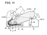
- FIGS. 8 to 11 show a second embodiment of the present invention, in which mounting shafts 55 are provided at the rear portion of the bottom cushion 15 and inserted into rear slots 56 disposed to the vertical plates 11 of the support frame 10 so as to move in a front-and-back direction.
- the tip anchor 41 and the tongue anchor 43 are locked to respective one ends of wire cables 57 and intermediate portions of the wire cables 57 are abutted on rollers 58 disposed to the outer peripheries of the mounting shafts 55.
- the other ends of the wire cables 57 are locked to the vertical plates 11 by.pins 59.
- the mounting shafts 55 (and the rollers 58) are also moved rearward at the same time. With this operation, the tip anchor 41 and the tongue anchor 43 are pulled a distance that is substantially twice the amount of rearward movement of the mounting shafts 55. As a result, the seat belt 40 is efficiently tightened and the vehicle seat occupant is more securely restrained by the seat belt 40.
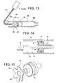
- FIGS. 12 to 15 show a third embodiment of the present invention, in which the tip anchor 41 and the tongue anchor 43 are locked to respective one ends of the wire cables 57, and intermediate portions of the wire cables 57 are abutted on the rollers 58 disposed on the mounting shafts 55, and the other ends of the wire cables 57 are coupled with seat belt pretensioner 60.
- the pretensioner 60 has a cylinder 63, a piston 61, and a piston rod 62, and each of the wire cables 57 is coupled with the piston rod 62.
- a gas chamber 64 is formed in the cylinder 63, and a large amount of gas from a gas generator 65, which is operated in response to a signal from the shock detection sensor 6, is supplied into the gas chamber 64.
- the tip anchor 41 and the tongue anchor 43 are pulled through the wire cables 57 and the seat belt 40 is placed in a strongly tightened state, thereby the vehicle seat occupant is more securely restrained by the seat belt 40.
- the third embodiment has a feature in that it is provided with the dedicated pretensioner 60 for tightening the seat belt 40 by pulling the tip anchor 41 and the tongue anchor 43 in addition to the pretensioner 30 for moving the bottom cushion 15 rearward.
- the piston 61 has a one-way lock 67.
- the one-way lock 67 has a plurality of claw-shaped projections 68 and the claw-shaped projections 68 are engaged with the inner wall of the cylinder 63 so that the piston 61 is regulated from moving leftward in FIG. 13 beyond a predetermined position.
- a seal ring 72 is disposed around the outer periphery of the piston 61.
- the shock detection sensor 6 detects an unpreferable external force which abruptly moves the vehicle seat occupant forward, the bottom cushion 15 moves rearward as well as the seat belt 40 is further tightened, and thus it is expected that the vehicle seat occupant can be more securely protected.
- the present invention since only the bottom cushion 15 can be moved rearward without substantially moving the seat back 2 of the vehicle seat 1, even a vehicle, which cannot secure a large space for movement behind the vehicle seat 1, can employ the vehicle seat of the present invention having the excellent function. In other words, in the present invention, almost no dead space is made behind the vehicle seat 1.
Landscapes
- Engineering & Computer Science (AREA)
- Mechanical Engineering (AREA)
- Aviation & Aerospace Engineering (AREA)
- Transportation (AREA)
- Seats For Vehicles (AREA)
- Automotive Seat Belt Assembly (AREA)
Abstract
Description
- The present invention relates to a vehicle seat for effectively protecting a vehicle seat occupant when an unpreferable external force acts on a vehicle body and abruptly moves the vehicle seat occupant forward, and more particularly to a vehicle seat for moving a bottom cushion rearward in quick response to generation of an unpreferable external force.
- Patent Document 1 discloses a conventional technique for quickly moving a vehicle seat (including a seat back and a seat bottom) rearward when an unpreferable external force acts on a vehicle body.
- Patent Document 1:
JP 2001-130354A - The known prior art has a problem in that both a seat back and a seat bottom of the vehicle seat move rearward. To move both the seat back and the seat bottom rearward, it is necessary to secure sufficient strength to a structure for moving them, and a large force and a large space are necessary to move them. Accordingly, the prior art is very disadvantageous in weight and size, and further it is difficult to employ the known technique in a small vehicle in which it is difficult to secure a space.
- Further, although a space behind the vehicle seat must be used as a dead space for receiving the vehicle seat in emergency, when a vehicle seat occupant sits on a rear seat contrary to the restraint, there is a possibility that the seat occupant sitting on the rear seat is secondarily injured by the vehicle seat that moves rearward in emergency.
- Accordingly, an object of the present invention is to provide an improved vehicle seat which overcomes the above problem.
- For this object, in the present invention, when an unpreferable external force acts on a vehicle body, only a bottom cushion is substantially moved rearward without moving a seat back and at the same time a seat belt is further tightened so that a vehicle seat occupant can be more securely protested.
-
-
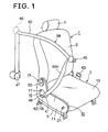
FIG. 1 is a perspective view showing an overall vehicle seat according to the present invention. -
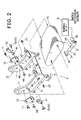
FIG. 2 is an exploded perspective view of the vehicle seat. -
FIG. 3 is a sectional view of a seat bottom of the vehicle seat. -
FIG. 4 is a side elevational view showing the vehicle seat and a vehicle seat occupant in an ordinary state. -
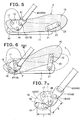
FIG. 5 is a side elevational view showing the relation between a bottom cushion and a support frame before collision. -
FIG. 6 is a side elevational view showing the relation between the bottom cushion and the support frame after collision. -
FIG. 7 is an explanatory view showing a moving distance T of the bottom cushion and a moving distance S of a tip anchor. -
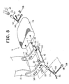
FIG. 8 is an exploded perspective view of a vehicle seat based on a second embodiment of the present invention. -
FIG. 9 is a sectional view of a seat bottom of the vehicle seat. -
FIG. 10 is a side elevational view showing the relation between a bottom cushion and a support frame before collision. -
FIG. 11 is a side elevational view showing the relation between the bottom cushion and the support frame after collision. -
FIG. 12 is an exploded perspective view of a vehicle seat based on a third embodiment of the present invention. -
FIG. 13 is a side elevational view showing a seat belt pretensioner and a tip anchor of the third embodiment. -
FIG. 14 is an enlarged sectional view of the seat belt pretensioner. -
FIG. 15 is a perspective view of a one-way lock of the seat belt pretensioner. - Embodiments of the present invention will be explained referring to the drawings. A vehicle seat 1 of the present invention has a
seat bottom 3, a seat back 2 journaled to theseat bottom 3 byshafts 73, and ahead rest 4 disposed to an upper portion of theseat back 2. Theseat back 2 is held at an optional angle with respect to theseat bottom 3 by a recliningmechanism 50. Theseat bottom 3 has asupport frame 10 and abottom cushion 15, and thesupport frame 10 is attached to a vehicle body 7 (FIG. 2 ) through a knownslide mechanism 5. - The
support frame 10 has a pair ofvertical plates 11 and acoupling member 12 interposed between thevertical plates bottom cushion 15 is substantially interposed between thevertical plates FIGS. 1 to 7 , afront link arm 20 is pivotably attached to a front side of each of thevertical plates 11 of thesupport frame 10 by ashaft 21, and a front side of thebottom cushion 15 is attached to an end of thefront link arm 20 by ashaft 22. - A triangular
rear link arm 16 is pivotably attached to a rear side of each of thevertical plates 11 of thesupport frame 10 by ashaft 17, and a rear portion of thebottom cushion 15 is pivotably attached to therear link arm 16 by acoupling shaft 18. - As shown in
FIG. 3 , thebottom cushion 15 has acushion frame 23, acushion material 24 attached to thecushion frame 23, and asurface skin 25 surrounding the outer periphery of thecushion material 24. - A
pretensioner 30 is disposed below thebottom cushion 15 to move thebottom cushion 15 relatively rearward with respect to the vehicle body 7 (thesupport frame 10 or the seat back 2). Thepretensioner 30 has acylinder 32, apiston 31, and agas generator 33 for supplying a large amount of gas into thecylinder 32 to push out thepiston 31. Apiston rod 34 is coupled with an end of thepiston 31 by a coupling pin or the like as necessary. The base portion of thecylinder 32 is attached to acoupling member 12 of the support frame 10 (or the bottom cushion 15), and the end of thepiston 31 is attached to the bottom cushion 15 (or the support frame 10). When thepiston 31 is pushed out from thecylinder 32, thebottom cushion 15 is moved relatively rearward with respect to the vehicle body 7. - When a
shock detection sensor 6, which is disposed at a desired position of the vehicle body 7, detects a shock (unpreferable external force that abruptly moves a vehicle seat occupant forward), thegas generator 33 instantly generates a large amount of gas and moves thepiston 31 rearward from thecylinder 32. - When a
shock detection sensor 6 disposed at a desired position of the vehicle body 7 detects a shock (unpreferable external force that abruptly moves a vehicle seat occupant forward), thegas generator 33 instantly generates a large amount of gas to move thepiston 31 rearward from thecylinder 32. When thegas generator 33 is operated, thebottom cushion 15 moves from a position shown inFIG. 5 to a position shown inFIG. 6 , a front side of thebottom cushion 15 moves rearward while moving upward, and a rear side thereof moves rearward while moving downward. The motion of thebottom cushion 15 will be described later in detail. - The vehicle seat 1 has a
seat belt mechanism 39. Theseat belt mechanism 39 has abelt retractor 47, aseat belt 40, ashoulder belt anchor 46, which holds an intermediate portion of theseat belt 40 at a predetermined height, atongue plate 45 coupled with theseat belt 40 in a middle portion thereof, atongue anchor 43 with which thetongue plate 45 is detachably engaged, atip anchor 41 to which an end of theseat belt 40 is fixed. When a strong load acts on theseat belt 40 by an accident or the like, theretractor 47 controls pulling out of theseat belt 40. Theretractor 47 is fixed to the vehicle body 7 or to the seat back 2. Thetip anchor 41 and thetongue anchor 43 are attached to therear link arms shafts coupling shafts shafts - Arc-
shaped guide grooves vertical plates shafts guide shafts rear link arms - As described above, when the
gas generator 33 is operated, a rear side of thebottom cushion 15 moves rearward while moving downward as shown inFIG. 7 . A supplementary explanation for this is given below. When thegas generator 33 is operated, thecoupling shafts 18 fixed to thebottom cushion 15 pivot therear link arms 16 clockwise about theshafts 17, thereby the coupling shafts 18 (which correspond to thetip anchor 41 and the tongue anchor 43) are moved a distance S. With this operation, theseat belt 40 is emergently tightened by the distance S. That is, after an accident or the like occurs, theseat belt 40 can be further tightened instantly than an ordinary state. With this operation, it can be expected to effectively protect a vehicle seat occupant by increasing the restraining function of theseat belt mechanism 39 as compared to the ordinary state, thereby an unpreferable space between the vehicle seat occupant and alap belt 40A of theseat belt 40 is suppressed. - Further, when the
gas generator 33 is operated, the front side of thebottom cushion 15 is moved upward. With this operation, the forward movement of the vehicle seat occupant can be further suppressed. - The amount of rearward movement of the
bottom cushion 15 is equal to a substantially horizontal distance T. When the distance S is set longer than the distance T, the vehicle seat occupant is protected by theseat belt mechanism 39 by a restraint force stronger than that before the accident occurs at the time thebottom cushion 15 is moved rearward by the action of thepretensioner 30. To set the distance S longer than the distance T, it is only sufficient to design these distances so that the distance T corresponds to a short side of a triangle and the distance S corresponds to a long side thereof. -
FIGS. 8 to 11 show a second embodiment of the present invention, in which mountingshafts 55 are provided at the rear portion of thebottom cushion 15 and inserted intorear slots 56 disposed to thevertical plates 11 of thesupport frame 10 so as to move in a front-and-back direction. Thetip anchor 41 and thetongue anchor 43 are locked to respective one ends ofwire cables 57 and intermediate portions of thewire cables 57 are abutted onrollers 58 disposed to the outer peripheries of themounting shafts 55. The other ends of thewire cables 57 are locked to thevertical plates 11 by.pins 59. - When the
bottom cushion 15 is moved rearward by the action of thepretensioner 30, the mounting shafts 55 (and the rollers 58) are also moved rearward at the same time. With this operation, thetip anchor 41 and thetongue anchor 43 are pulled a distance that is substantially twice the amount of rearward movement of the mountingshafts 55. As a result, theseat belt 40 is efficiently tightened and the vehicle seat occupant is more securely restrained by theseat belt 40. -
FIGS. 12 to 15 show a third embodiment of the present invention, in which thetip anchor 41 and thetongue anchor 43 are locked to respective one ends of thewire cables 57, and intermediate portions of thewire cables 57 are abutted on therollers 58 disposed on the mountingshafts 55, and the other ends of thewire cables 57 are coupled withseat belt pretensioner 60. - The
pretensioner 60 has acylinder 63, apiston 61, and apiston rod 62, and each of thewire cables 57 is coupled with thepiston rod 62. Agas chamber 64 is formed in thecylinder 63, and a large amount of gas from agas generator 65, which is operated in response to a signal from theshock detection sensor 6, is supplied into thegas chamber 64. When the gas is supplied into thegas chamber 64, thetip anchor 41 and thetongue anchor 43 are pulled through thewire cables 57 and theseat belt 40 is placed in a strongly tightened state, thereby the vehicle seat occupant is more securely restrained by theseat belt 40. As described above, the third embodiment has a feature in that it is provided with thededicated pretensioner 60 for tightening theseat belt 40 by pulling thetip anchor 41 and thetongue anchor 43 in addition to thepretensioner 30 for moving thebottom cushion 15 rearward. - The
piston 61 has a one-way lock 67. The one-way lock 67 has a plurality of claw-shapedprojections 68 and the claw-shapedprojections 68 are engaged with the inner wall of thecylinder 63 so that thepiston 61 is regulated from moving leftward inFIG. 13 beyond a predetermined position. Aseal ring 72 is disposed around the outer periphery of thepiston 61. - As described above, according to the present invention, when the
shock detection sensor 6 detects an unpreferable external force which abruptly moves the vehicle seat occupant forward, thebottom cushion 15 moves rearward as well as theseat belt 40 is further tightened, and thus it is expected that the vehicle seat occupant can be more securely protected. - Further, according to the present invention, since only the
bottom cushion 15 can be moved rearward without substantially moving the seat back 2 of the vehicle seat 1, even a vehicle, which cannot secure a large space for movement behind the vehicle seat 1, can employ the vehicle seat of the present invention having the excellent function. In other words, in the present invention, almost no dead space is made behind the vehicle seat 1.
Claims (4)
- A vehicle seat comprising:a seat bottom;a seat back pivotably attached to the seat bottom;a seat belt;said seat bottom having a support frame to be attached to a vehicle body, and a bottom cushion supported by the support frame;said support frame being arranged not to be moved in a front-and-back direction with respect to the vehicle body by an unpreferable external force which abruptly moves a vehicle seat occupant forward;said bottom cushion being arranged to be moveable in a front-and-back direction with respect to the support frame;a pretensioner disposed between the bottom cushion and the support frame to move the bottom cushion rearward with respect to the support frame when the unpreferable external force is generated;wherein a tip anchor and a tongue anchor of the seat belt are arranged to move in conjunction with the bottom cushion moving rearward to further tighten the seat belt when the pretensioner is actuated; andwherein a moving distance S of the tip anchor and the tongue anchor when the pretensioner is actuated is set larger than a moving distance T of the bottom cushion.
- The vehicle seat according to claim 1, further comprising rear link arms journaled to the support frame, wherein a rear portion of the bottom cushion is coupled with the rear link arms so that the rear link arms are pivoted as the bottom cushion moves rearward, and wherein the tip anchor and the tongue anchor are fixed to the rear link arms so that the seat belt is further tightened when the rear link arms are pivoted.
- The vehicle seat according to claim 1, wherein the tip anchor and the tongue anchor are connected to the support frame through wire cables, wherein rollers abutted on the wire cables are disposed to the bottom cushion, and wherein when the bottom cushion is moved rearward by the operation of the pretensioner, the rollers are abutted on the wire cables and move the tip anchor and the tongue anchor in a direction where the seat belt is tightened by a distance longer than the rearward moving distance of the bottom cushion.
- The vehicle seat according to claim 1, wherein the tip anchor and the tongue anchor are connected to seat belt pretensioner through wire cables, wherein when the unpreferable external force is generated, the bottom cushion is moved rearward by the pretensioner and the tip anchor and the tongue anchor are moved by the seat belt pretensioner in a direction where the seat belt is tightened.
Applications Claiming Priority (3)
| Application Number | Priority Date | Filing Date | Title |
|---|---|---|---|
| JP2006029080A JP4290703B2 (en) | 2006-02-06 | 2006-02-06 | Vehicle seat |
| JP2006029079A JP4290702B2 (en) | 2006-02-06 | 2006-02-06 | Vehicle seat |
| PCT/JP2007/052057 WO2007091575A1 (en) | 2006-02-06 | 2007-02-06 | Vehicle seat |
Publications (3)
| Publication Number | Publication Date |
|---|---|
| EP1987981A1 true EP1987981A1 (en) | 2008-11-05 |
| EP1987981A4 EP1987981A4 (en) | 2009-10-21 |
| EP1987981B1 EP1987981B1 (en) | 2011-06-08 |
Family
ID=38345171
Family Applications (1)
| Application Number | Title | Priority Date | Filing Date |
|---|---|---|---|
| EP07713886A Expired - Fee Related EP1987981B1 (en) | 2006-02-06 | 2007-02-06 | Vehicle seat |
Country Status (3)
| Country | Link |
|---|---|
| US (1) | US8109568B2 (en) |
| EP (1) | EP1987981B1 (en) |
| WO (1) | WO2007091575A1 (en) |
Cited By (1)
| Publication number | Priority date | Publication date | Assignee | Title |
|---|---|---|---|---|
| EP3656617A1 (en) * | 2013-06-21 | 2020-05-27 | Safran Seats USA LLC | Self-aligning safety belt |
Families Citing this family (18)
| Publication number | Priority date | Publication date | Assignee | Title |
|---|---|---|---|---|
| JP4290701B2 (en) * | 2006-01-13 | 2009-07-08 | テイ・エス テック株式会社 | Vehicle seat |
| JP5182843B2 (en) * | 2007-02-15 | 2013-04-17 | テイ・エス テック株式会社 | Vehicle seat |
| EP2154019B1 (en) * | 2007-02-28 | 2014-01-08 | TS Tech Co., Ltd. | Seat bottom pretensioner for vehicle seat |
| JP5170632B2 (en) * | 2007-12-21 | 2013-03-27 | テイ・エス テック株式会社 | Vehicle seat and method for assembling vehicle seat |
| JP5473322B2 (en) * | 2008-12-29 | 2014-04-16 | テイ・エス テック株式会社 | Vehicle seat |
| JP5395457B2 (en) * | 2009-02-25 | 2014-01-22 | テイ・エス テック株式会社 | Vehicle seat |
| US20120112503A1 (en) * | 2009-05-22 | 2012-05-10 | Ts Tech Co., Ltd. | Vehicle seat |
| DE102010062550A1 (en) * | 2009-12-09 | 2011-09-01 | Tk Holdings, Inc. | Occupant safety system |
| JP5486349B2 (en) * | 2010-03-01 | 2014-05-07 | テイ・エス テック株式会社 | Vehicle seat |
| CN103781661A (en) * | 2011-08-29 | 2014-05-07 | 丰田自动车株式会社 | Seat structure for vehicle |
| SE536013C2 (en) * | 2011-09-16 | 2013-04-02 | Bae Systems Haegglunds Ab | vehicle Seat |
| JP6173812B2 (en) * | 2013-07-18 | 2017-08-02 | タカタ株式会社 | Vehicle seat |
| JP6922756B2 (en) * | 2018-01-23 | 2021-08-18 | トヨタ自動車株式会社 | Vehicle seat belt device |
| US20190256039A1 (en) * | 2018-02-20 | 2019-08-22 | GM Global Technology Operations LLC | Systems and methods for a self-aligning restraint system |
| EP3552871B1 (en) * | 2018-04-10 | 2026-06-10 | Volvo Car Corporation | Method for adjusting a position of a vehicle seat |
| US10829015B2 (en) | 2018-10-11 | 2020-11-10 | Ford Global Technologies, Llc | Vehicle seat assembly |
| JP7040407B2 (en) * | 2018-11-05 | 2022-03-23 | トヨタ自動車株式会社 | Vehicle seat |
| US20230286426A1 (en) * | 2022-03-14 | 2023-09-14 | Institute For Injury Research | System and method for protecting an occupant in a rear impact of a vehicle |
Family Cites Families (15)
| Publication number | Priority date | Publication date | Assignee | Title |
|---|---|---|---|---|
| US3186760A (en) * | 1963-05-24 | 1965-06-01 | Gen Motors Corp | Combination seat belt anchoring and seat braking mechanism |
| DE2810231A1 (en) * | 1978-03-07 | 1979-09-13 | Adomeit Heinz Dieter Dipl Ing | DEVICE FOR TENSIONING A SEAT BELT FOR A MOTOR VEHICLE |
| US4738485A (en) * | 1986-10-16 | 1988-04-19 | Trw Vehicle Safety Systems, Inc. | Seat assembly with occupant restraint system |
| US5366269A (en) * | 1992-08-20 | 1994-11-22 | Life Force Associates, L.P. | Apparatus for restraining a passenger in a vehicle |
| US5567006A (en) * | 1993-10-01 | 1996-10-22 | Mccarthy; Joseph | Vehicle seat with articulated sections |
| DE29610078U1 (en) * | 1996-06-07 | 1996-10-02 | Trw Occupant Restraint Systems Gmbh, 73551 Alfdorf | Restraint system for vehicle occupants |
| FR2772690B1 (en) * | 1997-12-24 | 2000-02-18 | Faure Bertrand Equipements Sa | SEAT OF A MOTOR VEHICLE SEAT COMPRISING AN ANTI-SUBMARINE CROSSING |
| JP2001130354A (en) | 1999-08-24 | 2001-05-15 | Honda Motor Co Ltd | Occupant protection device |
| FR2798629B1 (en) * | 1999-09-16 | 2001-11-09 | Faure Bertrand Equipements Sa | SEAT OF A MOTOR VEHICLE SEAT COMPRISING AN ANTI-SUBMARINE CROSSING |
| JP2001163135A (en) * | 1999-12-06 | 2001-06-19 | Honda Motor Co Ltd | Occupant protection device |
| DE10052949B4 (en) * | 2000-10-25 | 2009-01-22 | C. Rob. Hammerstein Gmbh & Co. Kg | Digital tiling system for decoration of walls and floors in e.g. bathroom, has display device for reproducing digital image data, where display device is connected with feeding device for supplying image data and with power source |
| JP2003040013A (en) | 2001-07-30 | 2003-02-13 | Daihatsu Motor Co Ltd | Vehicle seat structure |
| US6682141B2 (en) * | 2001-09-14 | 2004-01-27 | The Boeing Company | Seat assembly having a seat repositioning device and an associated method |
| JP4069672B2 (en) * | 2002-05-15 | 2008-04-02 | トヨタ紡織株式会社 | Seat vertical device |
| JP4069688B2 (en) * | 2002-06-11 | 2008-04-02 | トヨタ紡織株式会社 | Seat vertical device |
-
2007
- 2007-02-06 WO PCT/JP2007/052057 patent/WO2007091575A1/en not_active Ceased
- 2007-02-06 EP EP07713886A patent/EP1987981B1/en not_active Expired - Fee Related
- 2007-02-06 US US12/278,465 patent/US8109568B2/en not_active Expired - Fee Related
Cited By (1)
| Publication number | Priority date | Publication date | Assignee | Title |
|---|---|---|---|---|
| EP3656617A1 (en) * | 2013-06-21 | 2020-05-27 | Safran Seats USA LLC | Self-aligning safety belt |
Also Published As
| Publication number | Publication date |
|---|---|
| US8109568B2 (en) | 2012-02-07 |
| US20100001559A1 (en) | 2010-01-07 |
| EP1987981B1 (en) | 2011-06-08 |
| EP1987981A4 (en) | 2009-10-21 |
| WO2007091575A1 (en) | 2007-08-16 |
Similar Documents
| Publication | Publication Date | Title |
|---|---|---|
| US8109568B2 (en) | Vehicle seat | |
| CN110861550B (en) | Vehicle seat | |
| US8573691B2 (en) | Vehicle seat | |
| JP5395457B2 (en) | Vehicle seat | |
| US20120112503A1 (en) | Vehicle seat | |
| JP6927059B2 (en) | Vehicle seat | |
| JP5201657B2 (en) | Vehicle seat | |
| JP5294444B2 (en) | Vehicle seat | |
| JP2019064548A (en) | Vehicle seat belt apparatus | |
| CN101415585B (en) | Vehicle seat | |
| JP2016193657A (en) | Buckle device and seat belt device provided with buckle device | |
| JP5105582B2 (en) | Vehicle seat | |
| JP4290703B2 (en) | Vehicle seat | |
| JP2016190596A (en) | Crew member protection device | |
| JP2010036693A (en) | Occupant crash protection system | |
| JP6555661B2 (en) | Crew protection device | |
| JP5311815B2 (en) | Vehicle seat | |
| JP2015080950A (en) | Occupant protection device of back seat | |
| JP7191069B2 (en) | seat belt device | |
| JP7145915B2 (en) | seat belt device | |
| JP2011173558A (en) | Pretensioner | |
| WO2009081900A1 (en) | Vehicle seat pretensioner and pretensioner assembling method | |
| JP2008238909A (en) | Vehicle seat system | |
| JP2023160507A (en) | vehicle seat | |
| WO2009081915A1 (en) | Vehicle seat and method of assembling vehicle seat |
Legal Events
| Date | Code | Title | Description |
|---|---|---|---|
| PUAI | Public reference made under article 153(3) epc to a published international application that has entered the european phase |
Free format text: ORIGINAL CODE: 0009012 |
|
| 17P | Request for examination filed |
Effective date: 20080905 |
|
| AK | Designated contracting states |
Kind code of ref document: A1 Designated state(s): DE FR GB |
|
| DAX | Request for extension of the european patent (deleted) | ||
| RBV | Designated contracting states (corrected) |
Designated state(s): DE FR GB |
|
| A4 | Supplementary search report drawn up and despatched |
Effective date: 20090923 |
|
| 17Q | First examination report despatched |
Effective date: 20091210 |
|
| GRAP | Despatch of communication of intention to grant a patent |
Free format text: ORIGINAL CODE: EPIDOSNIGR1 |
|
| RIC1 | Information provided on ipc code assigned before grant |
Ipc: B60R 21/02 20060101ALI20101110BHEP Ipc: B60N 2/02 20060101ALI20101110BHEP Ipc: B60N 2/42 20060101AFI20101110BHEP Ipc: B60R 22/26 20060101ALI20101110BHEP Ipc: B60R 22/46 20060101ALI20101110BHEP |
|
| GRAS | Grant fee paid |
Free format text: ORIGINAL CODE: EPIDOSNIGR3 |
|
| GRAA | (expected) grant |
Free format text: ORIGINAL CODE: 0009210 |
|
| AK | Designated contracting states |
Kind code of ref document: B1 Designated state(s): DE FR GB |
|
| REG | Reference to a national code |
Ref country code: GB Ref legal event code: FG4D |
|
| REG | Reference to a national code |
Ref country code: DE Ref legal event code: R096 Ref document number: 602007015060 Country of ref document: DE Effective date: 20110721 |
|
| PLBE | No opposition filed within time limit |
Free format text: ORIGINAL CODE: 0009261 |
|
| STAA | Information on the status of an ep patent application or granted ep patent |
Free format text: STATUS: NO OPPOSITION FILED WITHIN TIME LIMIT |
|
| 26N | No opposition filed |
Effective date: 20120309 |
|
| REG | Reference to a national code |
Ref country code: DE Ref legal event code: R097 Ref document number: 602007015060 Country of ref document: DE Effective date: 20120309 |
|
| REG | Reference to a national code |
Ref country code: FR Ref legal event code: PLFP Year of fee payment: 9 |
|
| PGFP | Annual fee paid to national office [announced via postgrant information from national office to epo] |
Ref country code: DE Payment date: 20150219 Year of fee payment: 9 |
|
| PGFP | Annual fee paid to national office [announced via postgrant information from national office to epo] |
Ref country code: FR Payment date: 20150219 Year of fee payment: 9 Ref country code: GB Payment date: 20150218 Year of fee payment: 9 |
|
| REG | Reference to a national code |
Ref country code: DE Ref legal event code: R119 Ref document number: 602007015060 Country of ref document: DE |
|
| GBPC | Gb: european patent ceased through non-payment of renewal fee |
Effective date: 20160206 |
|
| REG | Reference to a national code |
Ref country code: FR Ref legal event code: ST Effective date: 20161028 |
|
| PG25 | Lapsed in a contracting state [announced via postgrant information from national office to epo] |
Ref country code: DE Free format text: LAPSE BECAUSE OF NON-PAYMENT OF DUE FEES Effective date: 20160901 Ref country code: FR Free format text: LAPSE BECAUSE OF NON-PAYMENT OF DUE FEES Effective date: 20160229 Ref country code: GB Free format text: LAPSE BECAUSE OF NON-PAYMENT OF DUE FEES Effective date: 20160206 |