EP1987886A2 - Nozzle for spray guns - Google Patents
Nozzle for spray guns Download PDFInfo
- Publication number
- EP1987886A2 EP1987886A2 EP08380132A EP08380132A EP1987886A2 EP 1987886 A2 EP1987886 A2 EP 1987886A2 EP 08380132 A EP08380132 A EP 08380132A EP 08380132 A EP08380132 A EP 08380132A EP 1987886 A2 EP1987886 A2 EP 1987886A2
- Authority
- EP
- European Patent Office
- Prior art keywords
- chamber
- central
- peripheral
- nozzle
- air
- Prior art date
- Legal status (The legal status is an assumption and is not a legal conclusion. Google has not performed a legal analysis and makes no representation as to the accuracy of the status listed.)
- Granted
Links
- 239000007921 spray Substances 0.000 title claims abstract description 10
- 230000002093 peripheral effect Effects 0.000 claims abstract description 37
- 230000008602 contraction Effects 0.000 claims abstract description 14
- 239000012530 fluid Substances 0.000 claims description 16
- 230000000717 retained effect Effects 0.000 claims description 3
- 238000005507 spraying Methods 0.000 description 6
- 239000003973 paint Substances 0.000 description 2
- 238000004140 cleaning Methods 0.000 description 1
- 239000007788 liquid Substances 0.000 description 1
- 239000000126 substance Substances 0.000 description 1
Images

Classifications
-
- B—PERFORMING OPERATIONS; TRANSPORTING
- B05—SPRAYING OR ATOMISING IN GENERAL; APPLYING FLUENT MATERIALS TO SURFACES, IN GENERAL
- B05B—SPRAYING APPARATUS; ATOMISING APPARATUS; NOZZLES
- B05B7/00—Spraying apparatus for discharge of liquids or other fluent materials from two or more sources, e.g. of liquid and air, of powder and gas
- B05B7/02—Spray pistols; Apparatus for discharge
- B05B7/08—Spray pistols; Apparatus for discharge with separate outlet orifices, e.g. to form parallel jets, i.e. the axis of the jets being parallel, to form intersecting jets, i.e. the axis of the jets converging but not necessarily intersecting at a point
- B05B7/0807—Spray pistols; Apparatus for discharge with separate outlet orifices, e.g. to form parallel jets, i.e. the axis of the jets being parallel, to form intersecting jets, i.e. the axis of the jets converging but not necessarily intersecting at a point to form intersecting jets
- B05B7/0815—Spray pistols; Apparatus for discharge with separate outlet orifices, e.g. to form parallel jets, i.e. the axis of the jets being parallel, to form intersecting jets, i.e. the axis of the jets converging but not necessarily intersecting at a point to form intersecting jets with at least one gas jet intersecting a jet constituted by a liquid or a mixture containing a liquid for controlling the shape of the latter
Definitions
- the present invention relates to a nozzle for spray guns, especially designed for applying fluids, such as paints and the like.
- the nozzle of the invention is of the type defining two chambers: a central chamber and a peripheral chamber.
- the central chamber has a central opening, through which there emerges the outlet of the chamber for supplying the fluid to be sprayed, and a series of central holes for the exit of pressurized air supplied by the gun.
- the peripheral chamber has a series of peripheral holes, also for the exit of pressurized air supplied by the gun. The pressurized air coming out through the central and peripheral holes causes the spraying and projection of the paint or liquid to be sprayed.
- the pressurized air coming out through the central and peripheral holes of the nozzle must be useful for achieving a suitable spraying and projection of the fluid to be sprayed.
- This circumstance makes it necessary to have different guns, each one suitable to provide air at the suitable pressure and with the suitable direction to achieve the desired spraying and projection.
- This solution is expensive because it forces having as many different spray guns as the different applications that can exist.
- the nozzle comprises means for controlling the pressure of the air reaching the central and peripheral exit holes, as well as for controlling the air exit direction.
- the means for controlling the pressure of the air consist of contractions of the air passage section located in the peripheral and central chambers.
- the means for directing the exit of the air consist of changing the inclination of the central and peripheral air exit holes.
- the contraction in the passage section of the peripheral chamber is caused in the nozzle of the invention by a washer which is arranged between the walls of the peripheral chamber of the nozzle, being supported on the edge of the outer wall and defining with the inner wall a narrow ring-shaped passageway making the air flow laminar so that it reaches in a completely guided manner the area from which the peripheral exit holes start, which holes will be suitably positioned both in dimensions and in heights and angles.
- the mentioned washer is retained by a ring-shaped spring which is assembled between said washer and the nut for assembling the nozzle in the gun.
- the contraction in the passage section of the central chamber is achieved by means of a ring-shaped rib of the inner surface of the wall of the central chamber, the rib of which is opposite to the wall of chamber for supplying the pressurized fluid, running in a centered position through the gun to the nozzle, in order to the emerge through the central hole thereof.
- the rib determines with the chamber for conducting the fluid to be sprayed a ring-shaped passageway with a section much smaller than that of said chamber.
- the mentioned ring-shaped passageway makes the air flow laminar and allows the passage of a certain amount of such air, finally reaching the area from which the central holes start for its exit therethrough as well as also through the ring-shaped passageway defined by the central opening with the outlet of the chamber for supplying the fluid to be sprayed.
- a suitable air exit or spraying is achieved with the nozzle of the invention as a correct distribution of compressed air is ensured in the areas from which the central and peripheral holes start, all of this as a result of the mentioned contractions, by means of which each of the mentioned areas receives an exact amount of air and at a certain pressure which, in addition to a correctly selected inclination of the central and peripheral air exit holes, allows very accurately distributing the amount of air that each spray nozzle needs and in the correct ratio.
- the nozzle of the invention can furthermore be easily assembled and disassembled and also allows easily cleaning the assembly.
- the air fluids can be better distributed and made laminar as a result of the mentioned contractions.
- the attached drawings show a nozzle for spray guns formed according to the invention, and aid in better understating the makeup, features and advantages of the nozzle.
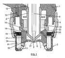
- Figure 1 partially shows the body of a spray gun, in which the nozzle 2 of the invention is coupled by means of nut 3.
- the chamber 4 for supplying the fluid to be sprayed runs through the inside of the body of the gun 1, which chamber has an outlet 5 which can be blocked by means of the needle 6 which can be actuated by the gun.
- the nozzle 2 Once the nozzle 2 has been assembled in the gun 1, it defines a central chamber 7 and a peripheral chamber 8.
- the central chamber 7 has a central opening 9 through which there emerges the outlet 5 of the chamber 4 for supplying the fluid to be sprayed.
- the central chamber 7 also has a series of central holes 10 for the exit of pressurized air.
- the peripheral chamber 8 in turn has a series of peripheral holes 11, also for the exit of pressurized air.
- the pressurized air is supplied by the gun 1 through two groups of ducts 12 and 13.
- the pressurized air reaches the central chamber 7 through ducts 12 and passageways 14, passing through a ring-shaped contraction 15 defined between the wall of the chamber 4 and a rib 16 projecting from the inner wall of the nozzle 2.
- the passageway 15 makes the air flow laminar and allows the passage of a certain amount of such air.
- the air reaches the central chamber 7 in these conditions, where it is distributed and will come out through the holes 10 and through the ring-shaped section 17 confined between the central opening 9 of the nozzle and the outlet 5 of the chamber 4 for conducting the fluid to be sprayed.
- the nozzle 2 Before the peripheral chamber 8, the nozzle 2 includes a washer 18 which is supported against the edge of the outer wall 19 of the nozzle 2 and is retained by means of a ring-shaped spring 20 assembled between said washer and the lock nut 3 of the nozzle.
- the washer 18 determines with the inner wall 21 of the nozzle 2 a ring-shaped passageway 22 forming a contraction for the passage of the air, making its flow laminar so that it reaches in a completely guided manner the peripheral chamber 8 and then the peripheral exit holes 11.
- a correct distribution of the compressed air is achieved by means of ring-shaped contractions 15 and 22, so that the necessary amount of air reaches each central chamber 7 and peripheral chamber 8 at the suitable pressure.
- the contractions 15 and 22 allow a suitable control of the correct air flow rate and pressure for each nozzle.
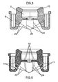
- Figure 3 shows in a lower plan view of the nozzle the position of the central holes 10 and peripheral holes 11, as well as the ring-shaped passageway 17 confined between the central opening 9 and the outlet 5 of the chamber for supplying the fluid to be distributed.
- Figure 2 shows the exit direction of air jets 24 through central holes 10, and of air jets 25 through exit holes 11. Another distribution, such as that shown in Figures 4 , 5 and 6 , can be achieved by changing the section, position and inclination of these holes.
- air jets 25 define a closer angle than in the case of Figure 2 , whereas jets 24 have considerably parallel exit directions.
- jets 25 meet at one and the same vertex 26, whereas jets 24 have considerably parallel directions.
Abstract
Description
- The present invention relates to a nozzle for spray guns, especially designed for applying fluids, such as paints and the like.
- More specifically, the nozzle of the invention is of the type defining two chambers: a central chamber and a peripheral chamber. The central chamber has a central opening, through which there emerges the outlet of the chamber for supplying the fluid to be sprayed, and a series of central holes for the exit of pressurized air supplied by the gun. The peripheral chamber has a series of peripheral holes, also for the exit of pressurized air supplied by the gun. The pressurized air coming out through the central and peripheral holes causes the spraying and projection of the paint or liquid to be sprayed.
- The pressurized air coming out through the central and peripheral holes of the nozzle must be useful for achieving a suitable spraying and projection of the fluid to be sprayed. Depending on the characteristics of this fluid and the specific application thereof, it will be necessary to change the conditions of the pressurized air, both the exit pressure and the direction thereof. This circumstance makes it necessary to have different guns, each one suitable to provide air at the suitable pressure and with the suitable direction to achieve the desired spraying and projection. This solution is expensive because it forces having as many different spray guns as the different applications that can exist.
- The object of the present invention is to eliminate the problem set forth by means of a nozzle formed such that it defines the exit conditions of the air, regardless of the features of the gun to which the nozzle is applied.
- Different exit conditions of the pressurized air can thus be achieved by having nozzles with different features, therefore, different conditions of pressurized air supplied by the nozzle can be achieved with a single gun by simply changing the type of nozzle assembled in the gun.
- To that end, according to the present invention, the nozzle comprises means for controlling the pressure of the air reaching the central and peripheral exit holes, as well as for controlling the air exit direction. The means for controlling the pressure of the air consist of contractions of the air passage section located in the peripheral and central chambers. The means for directing the exit of the air consist of changing the inclination of the central and peripheral air exit holes.
- The contraction in the passage section of the peripheral chamber is caused in the nozzle of the invention by a washer which is arranged between the walls of the peripheral chamber of the nozzle, being supported on the edge of the outer wall and defining with the inner wall a narrow ring-shaped passageway making the air flow laminar so that it reaches in a completely guided manner the area from which the peripheral exit holes start, which holes will be suitably positioned both in dimensions and in heights and angles. The mentioned washer is retained by a ring-shaped spring which is assembled between said washer and the nut for assembling the nozzle in the gun.
- The contraction in the passage section of the central chamber is achieved by means of a ring-shaped rib of the inner surface of the wall of the central chamber, the rib of which is opposite to the wall of chamber for supplying the pressurized fluid, running in a centered position through the gun to the nozzle, in order to the emerge through the central hole thereof. The rib determines with the chamber for conducting the fluid to be sprayed a ring-shaped passageway with a section much smaller than that of said chamber. The mentioned ring-shaped passageway makes the air flow laminar and allows the passage of a certain amount of such air, finally reaching the area from which the central holes start for its exit therethrough as well as also through the ring-shaped passageway defined by the central opening with the outlet of the chamber for supplying the fluid to be sprayed.
- In short, by means of the contractions caused in the two chambers, it is achieved that the air reaching the areas from which the central and peripheral holes start does so at the suitable pressure, coming out through both holes in a correctly conducted manner as a result of the inclination of such holes, which will depend in each nozzle on the fluid to be sprayed for which it is intended.
- A suitable air exit or spraying is achieved with the nozzle of the invention as a correct distribution of compressed air is ensured in the areas from which the central and peripheral holes start, all of this as a result of the mentioned contractions, by means of which each of the mentioned areas receives an exact amount of air and at a certain pressure which, in addition to a correctly selected inclination of the central and peripheral air exit holes, allows very accurately distributing the amount of air that each spray nozzle needs and in the correct ratio.
- In short, correct control of the air flow rate and pressure, an improvement in the finishing of the sprayed fluids is achieved with the nozzle of the invention, and all of this as a result of the fact that each air nozzle incorporates the necessary elements for its correct operation.
- The nozzle of the invention can furthermore be easily assembled and disassembled and also allows easily cleaning the assembly.
- The air fluids can be better distributed and made laminar as a result of the mentioned contractions.
- The attached drawings show a nozzle for spray guns formed according to the invention, and aid in better understating the makeup, features and advantages of the nozzle.
- In the drawings:
-
Figure 1 is a diametrical section of a nozzle formed according to the invention, assembled in a spray gun. -
Figure 2 is a diametrical section of the nozzle, showing the air exit direction through the central and peripheral holes. -
Figure 3 is a lower plan view of the nozzle. -
Figures 4 ,5 and 6 are views similar toFigure 2 , showing implementation variants in relation to the section and inclination of the central and peripheral air exit holes. -
Figure 1 partially shows the body of a spray gun, in which thenozzle 2 of the invention is coupled by means ofnut 3. Thechamber 4 for supplying the fluid to be sprayed runs through the inside of the body of thegun 1, which chamber has anoutlet 5 which can be blocked by means of theneedle 6 which can be actuated by the gun. - Once the
nozzle 2 has been assembled in thegun 1, it defines acentral chamber 7 and aperipheral chamber 8. - The
central chamber 7 has acentral opening 9 through which there emerges theoutlet 5 of thechamber 4 for supplying the fluid to be sprayed. Thecentral chamber 7 also has a series ofcentral holes 10 for the exit of pressurized air. - The
peripheral chamber 8 in turn has a series ofperipheral holes 11, also for the exit of pressurized air. - The pressurized air is supplied by the
gun 1 through two groups ofducts central chamber 7 throughducts 12 andpassageways 14, passing through a ring-shaped contraction 15 defined between the wall of thechamber 4 and arib 16 projecting from the inner wall of thenozzle 2. Thepassageway 15 makes the air flow laminar and allows the passage of a certain amount of such air. The air reaches thecentral chamber 7 in these conditions, where it is distributed and will come out through theholes 10 and through the ring-shaped section 17 confined between thecentral opening 9 of the nozzle and theoutlet 5 of thechamber 4 for conducting the fluid to be sprayed. - Before the
peripheral chamber 8, thenozzle 2 includes awasher 18 which is supported against the edge of theouter wall 19 of thenozzle 2 and is retained by means of a ring-shaped spring 20 assembled between said washer and thelock nut 3 of the nozzle. Thewasher 18 determines with theinner wall 21 of the nozzle 2 a ring-shaped passageway 22 forming a contraction for the passage of the air, making its flow laminar so that it reaches in a completely guided manner theperipheral chamber 8 and then theperipheral exit holes 11. - A correct distribution of the compressed air is achieved by means of ring-
shaped contractions 15 and 22, so that the necessary amount of air reaches eachcentral chamber 7 andperipheral chamber 8 at the suitable pressure. By combining these conditions with a correct inclination of thecentral holes 10 andperipheral holes 11, the amount of air that each spray nozzle needs is very accurately distributed and is in the correct ratio and direction to achieve a perfect spraying of the fluid contained inchamber 4, supplied throughoutlet 5, when theneedle 6 is retracted by the actuation controls of thegun 1. - The
contractions 15 and 22 allow a suitable control of the correct air flow rate and pressure for each nozzle. -
Figure 3 shows in a lower plan view of the nozzle the position of thecentral holes 10 andperipheral holes 11, as well as the ring-shaped passageway 17 confined between thecentral opening 9 and theoutlet 5 of the chamber for supplying the fluid to be distributed. -
Figure 2 shows the exit direction ofair jets 24 throughcentral holes 10, and ofair jets 25 throughexit holes 11. Another distribution, such as that shown inFigures 4 ,5 and 6 , can be achieved by changing the section, position and inclination of these holes. InFigure 4 air jets 25 define a closer angle than in the case ofFigure 2 , whereasjets 24 have considerably parallel exit directions. In the case ofFigure 5 ,jets 25 meet at one and thesame vertex 26, whereasjets 24 have considerably parallel directions. - In the case of
Figure 6 there is a larger number ofcentral holes 10, thejets 24 of which converge slightly with one another, whereasair jets 25 cross one another near the corresponding vertices. - With the described constitution, by means of a single gun having different nozzles, different spraying conditions suitable for the substance to be sprayed can be obtained, which involves considerable savings given that the cost of the nozzles is extremely reduced compared to that of the gun assembly.
Claims (3)
- A nozzle for spray guns, defining a central chamber and a peripheral chamber, the central chamber of which has a central opening, through which there emerges the outlet of the chamber for supplying the fluid to be sprayed, and a series of central air exit holes, and the peripheral chamber of which has a series of peripheral air exit holes, characterized in that it comprises means for controlling the pressure of the air reaching the central and peripheral exit holes; which means consist of contractions of the air passage section located in the peripheral and central chambers.
- A nozzle according to claim 1, characterized in that the contraction in the passage section of the peripheral chamber is caused by a washer which is arranged between inner and outer walls delimiting the peripheral chamber of the nozzle, being supported on the edge of the outer wall and defining with the inner wall a narrow ring-shaped passageway, which washer is retained by a ring-shaped spring assembled between said washer and the nut for assembling the gun.
- A nozzle according to claim 1, characterized in that the contraction in the passage section of the central chamber is caused by a ring-shaped rib of the inner surface of the inner wall of the nozzle delimiting the central chamber, which rib is opposite to the wall of the chamber for supplying the product to be sprayed, determining therewith a ring-shaped passageway with a section much smaller than that of said chamber.
Applications Claiming Priority (1)
| Application Number | Priority Date | Filing Date | Title |
|---|---|---|---|
| ES200701164A ES2283238B1 (en) | 2007-04-30 | 2007-04-30 | NOZZLE FOR AIR GUNS. |
Publications (3)
| Publication Number | Publication Date |
|---|---|
| EP1987886A2 true EP1987886A2 (en) | 2008-11-05 |
| EP1987886A3 EP1987886A3 (en) | 2012-04-18 |
| EP1987886B1 EP1987886B1 (en) | 2014-08-13 |
Family
ID=38556507
Family Applications (1)
| Application Number | Title | Priority Date | Filing Date |
|---|---|---|---|
| EP20080380132 Active EP1987886B1 (en) | 2007-04-30 | 2008-04-30 | Nozzle for spray guns |
Country Status (2)
| Country | Link |
|---|---|
| EP (1) | EP1987886B1 (en) |
| ES (2) | ES2283238B1 (en) |
Cited By (4)
| Publication number | Priority date | Publication date | Assignee | Title |
|---|---|---|---|---|
| WO2018184636A3 (en) * | 2018-08-01 | 2019-06-20 | Sata Gmbh & Co. Kg | Set of nozzles for a spray gun, spray gun system, method for embodying a nozzle module, method for seelcting a nozzle module from a set of nozzles for a paint job, selection system and computer program product |
| US11141747B2 (en) | 2015-05-22 | 2021-10-12 | Sata Gmbh & Co. Kg | Nozzle arrangement for a spray gun |
| US11801521B2 (en) | 2018-08-01 | 2023-10-31 | Sata Gmbh & Co. Kg | Main body for a spray gun, spray guns, spray gun set, method for producing a main body for a spray gun and method for converting a spray gun |
| US11865558B2 (en) | 2018-08-01 | 2024-01-09 | Sata Gmbh & Co. Kg | Nozzle for a spray gun, nozzle set for a spray gun, spray guns and methods for producing a nozzle for a spray gun |
Families Citing this family (1)
| Publication number | Priority date | Publication date | Assignee | Title |
|---|---|---|---|---|
| US11020759B2 (en) | 2016-04-20 | 2021-06-01 | Carlisle Fluid Technologies, Inc. | System for controlling air shaping flow in spray cap of spray tool |
Citations (2)
| Publication number | Priority date | Publication date | Assignee | Title |
|---|---|---|---|---|
| US20060016909A1 (en) * | 2004-07-23 | 2006-01-26 | Chia Chung Enterprises Co., Ltd. | Spray gun head |
| US20070262169A1 (en) * | 2006-05-01 | 2007-11-15 | Chia Chung Precision Industrial Co., Ltd. | Spray head structure of a spray gun |
Family Cites Families (4)
| Publication number | Priority date | Publication date | Assignee | Title |
|---|---|---|---|---|
| US2303280A (en) * | 1940-09-09 | 1942-11-24 | Alexander F Jenkins | Spray gun |
| US5209405A (en) * | 1991-04-19 | 1993-05-11 | Ransburg Corporation | Baffle for hvlp paint spray gun |
| US6471144B1 (en) * | 2000-10-23 | 2002-10-29 | Tiao-Hsiang Huang | Structure of spray gun air guide nozzle with dual pressure reduction |
| FR2839663B1 (en) * | 2002-05-16 | 2004-07-23 | Itw Surfaces & Finitions | SPRAY HEAD OF A PRODUCT SUCH AS PAINT |
-
2007
- 2007-04-30 ES ES200701164A patent/ES2283238B1/en not_active Expired - Fee Related
-
2008
- 2008-04-30 EP EP20080380132 patent/EP1987886B1/en active Active
- 2008-04-30 ES ES08380132.4T patent/ES2527345T3/en active Active
Patent Citations (2)
| Publication number | Priority date | Publication date | Assignee | Title |
|---|---|---|---|---|
| US20060016909A1 (en) * | 2004-07-23 | 2006-01-26 | Chia Chung Enterprises Co., Ltd. | Spray gun head |
| US20070262169A1 (en) * | 2006-05-01 | 2007-11-15 | Chia Chung Precision Industrial Co., Ltd. | Spray head structure of a spray gun |
Non-Patent Citations (1)
| Title |
|---|
| Chia Chung: "Improved structure of spray gun nozzle", , 26 November 2006 (2006-11-26), XP55020989, Retrieved from the Internet: URL:http://twpat2.tipo.gov.tw/tipotwousr/00549/ga-M291843.pdf [retrieved on 2012-03-06] * |
Cited By (6)
| Publication number | Priority date | Publication date | Assignee | Title |
|---|---|---|---|---|
| US11141747B2 (en) | 2015-05-22 | 2021-10-12 | Sata Gmbh & Co. Kg | Nozzle arrangement for a spray gun |
| WO2018184636A3 (en) * | 2018-08-01 | 2019-06-20 | Sata Gmbh & Co. Kg | Set of nozzles for a spray gun, spray gun system, method for embodying a nozzle module, method for seelcting a nozzle module from a set of nozzles for a paint job, selection system and computer program product |
| CN112533705A (en) * | 2018-08-01 | 2021-03-19 | 萨塔有限两合公司 | Nozzle group for a spray gun, spray gun system, method for producing a nozzle module, method for selecting a nozzle module from a nozzle group for a painting task, selection system and computer program product |
| US11801521B2 (en) | 2018-08-01 | 2023-10-31 | Sata Gmbh & Co. Kg | Main body for a spray gun, spray guns, spray gun set, method for producing a main body for a spray gun and method for converting a spray gun |
| US11826771B2 (en) | 2018-08-01 | 2023-11-28 | Sata Gmbh & Co. Kg | Set of nozzles for a spray gun, spray gun system, method for embodying a nozzle module, method for selecting a nozzle module from a set of nozzles for a paint job, selection system and computer program product |
| US11865558B2 (en) | 2018-08-01 | 2024-01-09 | Sata Gmbh & Co. Kg | Nozzle for a spray gun, nozzle set for a spray gun, spray guns and methods for producing a nozzle for a spray gun |
Also Published As
| Publication number | Publication date |
|---|---|
| ES2527345T3 (en) | 2015-01-22 |
| EP1987886B1 (en) | 2014-08-13 |
| ES2283238B1 (en) | 2009-03-16 |
| EP1987886A3 (en) | 2012-04-18 |
| ES2283238A1 (en) | 2007-10-16 |
Similar Documents
| Publication | Publication Date | Title |
|---|---|---|
| EP1765511B1 (en) | Fluid atomizing system and method | |
| JP6463802B2 (en) | Spray coating equipment and system | |
| CN106714975B (en) | Low pressure spray head structure | |
| US5165605A (en) | Low pressure air atomizing spray gun | |
| EP1987886B1 (en) | Nozzle for spray guns | |
| DK2885083T3 (en) | FULL CONE AIR SUPPORTED SPRAY NOZZLE DEVICE | |
| KR102512019B1 (en) | Device for rotating a fluid inside a spray nozzle, assembly comprising such a device and coating device | |
| US20080048055A1 (en) | Spray gun having mechanism for internally swirling and breaking up a fluid | |
| CN1397381A (en) | Spray gun | |
| JP2004074155A (en) | Spray gun with improved atomization | |
| EP1075333B1 (en) | Micro spray gun | |
| CA2641508A1 (en) | Spray coating system and method | |
| KR20060104642A (en) | Paint sprayer | |
| EP0411830B1 (en) | Low pressure air atomizing spray gun | |
| US11701670B2 (en) | Spray tip | |
| IT202000000761U1 (en) | HEAD FOR PAINT GUN | |
| GB2063713A (en) | Spray guns | |
| JP7431021B2 (en) | spray gun | |
| EP1316364A1 (en) | Internal impingement nozzle | |
| JPH0330853A (en) | Spray apparatus | |
| JPH07275744A (en) | Spray coating device | |
| JPH03275158A (en) | Bendable-neck spray gun |
Legal Events
| Date | Code | Title | Description |
|---|---|---|---|
| PUAI | Public reference made under article 153(3) epc to a published international application that has entered the european phase |
Free format text: ORIGINAL CODE: 0009012 |
|
| AK | Designated contracting states |
Kind code of ref document: A2 Designated state(s): AT BE BG CH CY CZ DE DK EE ES FI FR GB GR HR HU IE IS IT LI LT LU LV MC MT NL NO PL PT RO SE SI SK TR |
|
| AX | Request for extension of the european patent |
Extension state: AL BA MK RS |
|
| PUAL | Search report despatched |
Free format text: ORIGINAL CODE: 0009013 |
|
| AK | Designated contracting states |
Kind code of ref document: A3 Designated state(s): AT BE BG CH CY CZ DE DK EE ES FI FR GB GR HR HU IE IS IT LI LT LU LV MC MT NL NO PL PT RO SE SI SK TR |
|
| AX | Request for extension of the european patent |
Extension state: AL BA MK RS |
|
| RIC1 | Information provided on ipc code assigned before grant |
Ipc: B05B 7/12 20060101ALN20120312BHEP Ipc: B05B 7/08 20060101ALI20120312BHEP Ipc: B05B 7/06 20060101AFI20120312BHEP |
|
| 17P | Request for examination filed |
Effective date: 20120904 |
|
| AKX | Designation fees paid |
Designated state(s): AT BE BG CH CY CZ DE DK EE ES FI FR GB GR HR HU IE IS IT LI LT LU LV MC MT NL NO PL PT RO SE SI SK TR |
|
| RIC1 | Information provided on ipc code assigned before grant |
Ipc: B05B 7/12 20060101ALN20140110BHEP Ipc: B05B 7/08 20060101ALI20140110BHEP Ipc: B05B 7/06 20060101AFI20140110BHEP |
|
| GRAP | Despatch of communication of intention to grant a patent |
Free format text: ORIGINAL CODE: EPIDOSNIGR1 |
|
| INTG | Intention to grant announced |
Effective date: 20140425 |
|
| RIC1 | Information provided on ipc code assigned before grant |
Ipc: B05B 7/12 20060101ALN20140411BHEP Ipc: B05B 7/06 20060101AFI20140411BHEP Ipc: B05B 7/08 20060101ALI20140411BHEP |
|
| RIN1 | Information on inventor provided before grant (corrected) |
Inventor name: SANCHEZ URIONDO, ENRIQUE |
|
| GRAS | Grant fee paid |
Free format text: ORIGINAL CODE: EPIDOSNIGR3 |
|
| GRAA | (expected) grant |
Free format text: ORIGINAL CODE: 0009210 |
|
| AK | Designated contracting states |
Kind code of ref document: B1 Designated state(s): AT BE BG CH CY CZ DE DK EE ES FI FR GB GR HR HU IE IS IT LI LT LU LV MC MT NL NO PL PT RO SE SI SK TR |
|
| REG | Reference to a national code |
Ref country code: GB Ref legal event code: FG4D |
|
| REG | Reference to a national code |
Ref country code: CH Ref legal event code: EP Ref country code: AT Ref legal event code: REF Ref document number: 681868 Country of ref document: AT Kind code of ref document: T Effective date: 20140815 |
|
| REG | Reference to a national code |
Ref country code: IE Ref legal event code: FG4D |
|
| REG | Reference to a national code |
Ref country code: DE Ref legal event code: R096 Ref document number: 602008033804 Country of ref document: DE Effective date: 20141002 |
|
| REG | Reference to a national code |
Ref country code: NL Ref legal event code: VDEP Effective date: 20140813 |
|
| REG | Reference to a national code |
Ref country code: AT Ref legal event code: MK05 Ref document number: 681868 Country of ref document: AT Kind code of ref document: T Effective date: 20140813 |
|
| REG | Reference to a national code |
Ref country code: ES Ref legal event code: FG2A Ref document number: 2527345 Country of ref document: ES Kind code of ref document: T3 Effective date: 20150122 |
|
| REG | Reference to a national code |
Ref country code: LT Ref legal event code: MG4D |
|
| PG25 | Lapsed in a contracting state [announced via postgrant information from national office to epo] |
Ref country code: NO Free format text: LAPSE BECAUSE OF FAILURE TO SUBMIT A TRANSLATION OF THE DESCRIPTION OR TO PAY THE FEE WITHIN THE PRESCRIBED TIME-LIMIT Effective date: 20141113 Ref country code: LT Free format text: LAPSE BECAUSE OF FAILURE TO SUBMIT A TRANSLATION OF THE DESCRIPTION OR TO PAY THE FEE WITHIN THE PRESCRIBED TIME-LIMIT Effective date: 20140813 Ref country code: FI Free format text: LAPSE BECAUSE OF FAILURE TO SUBMIT A TRANSLATION OF THE DESCRIPTION OR TO PAY THE FEE WITHIN THE PRESCRIBED TIME-LIMIT Effective date: 20140813 Ref country code: PT Free format text: LAPSE BECAUSE OF FAILURE TO SUBMIT A TRANSLATION OF THE DESCRIPTION OR TO PAY THE FEE WITHIN THE PRESCRIBED TIME-LIMIT Effective date: 20141215 Ref country code: SE Free format text: LAPSE BECAUSE OF FAILURE TO SUBMIT A TRANSLATION OF THE DESCRIPTION OR TO PAY THE FEE WITHIN THE PRESCRIBED TIME-LIMIT Effective date: 20140813 Ref country code: GR Free format text: LAPSE BECAUSE OF FAILURE TO SUBMIT A TRANSLATION OF THE DESCRIPTION OR TO PAY THE FEE WITHIN THE PRESCRIBED TIME-LIMIT Effective date: 20141114 Ref country code: BG Free format text: LAPSE BECAUSE OF FAILURE TO SUBMIT A TRANSLATION OF THE DESCRIPTION OR TO PAY THE FEE WITHIN THE PRESCRIBED TIME-LIMIT Effective date: 20141113 |
|
| PG25 | Lapsed in a contracting state [announced via postgrant information from national office to epo] |
Ref country code: IS Free format text: LAPSE BECAUSE OF FAILURE TO SUBMIT A TRANSLATION OF THE DESCRIPTION OR TO PAY THE FEE WITHIN THE PRESCRIBED TIME-LIMIT Effective date: 20141213 Ref country code: LV Free format text: LAPSE BECAUSE OF FAILURE TO SUBMIT A TRANSLATION OF THE DESCRIPTION OR TO PAY THE FEE WITHIN THE PRESCRIBED TIME-LIMIT Effective date: 20140813 Ref country code: HR Free format text: LAPSE BECAUSE OF FAILURE TO SUBMIT A TRANSLATION OF THE DESCRIPTION OR TO PAY THE FEE WITHIN THE PRESCRIBED TIME-LIMIT Effective date: 20140813 Ref country code: CY Free format text: LAPSE BECAUSE OF FAILURE TO SUBMIT A TRANSLATION OF THE DESCRIPTION OR TO PAY THE FEE WITHIN THE PRESCRIBED TIME-LIMIT Effective date: 20140813 Ref country code: AT Free format text: LAPSE BECAUSE OF FAILURE TO SUBMIT A TRANSLATION OF THE DESCRIPTION OR TO PAY THE FEE WITHIN THE PRESCRIBED TIME-LIMIT Effective date: 20140813 |
|
| PG25 | Lapsed in a contracting state [announced via postgrant information from national office to epo] |
Ref country code: NL Free format text: LAPSE BECAUSE OF FAILURE TO SUBMIT A TRANSLATION OF THE DESCRIPTION OR TO PAY THE FEE WITHIN THE PRESCRIBED TIME-LIMIT Effective date: 20140813 |
|
| PG25 | Lapsed in a contracting state [announced via postgrant information from national office to epo] |
Ref country code: RO Free format text: LAPSE BECAUSE OF FAILURE TO SUBMIT A TRANSLATION OF THE DESCRIPTION OR TO PAY THE FEE WITHIN THE PRESCRIBED TIME-LIMIT Effective date: 20140813 Ref country code: DK Free format text: LAPSE BECAUSE OF FAILURE TO SUBMIT A TRANSLATION OF THE DESCRIPTION OR TO PAY THE FEE WITHIN THE PRESCRIBED TIME-LIMIT Effective date: 20140813 Ref country code: CZ Free format text: LAPSE BECAUSE OF FAILURE TO SUBMIT A TRANSLATION OF THE DESCRIPTION OR TO PAY THE FEE WITHIN THE PRESCRIBED TIME-LIMIT Effective date: 20140813 Ref country code: EE Free format text: LAPSE BECAUSE OF FAILURE TO SUBMIT A TRANSLATION OF THE DESCRIPTION OR TO PAY THE FEE WITHIN THE PRESCRIBED TIME-LIMIT Effective date: 20140813 Ref country code: SK Free format text: LAPSE BECAUSE OF FAILURE TO SUBMIT A TRANSLATION OF THE DESCRIPTION OR TO PAY THE FEE WITHIN THE PRESCRIBED TIME-LIMIT Effective date: 20140813 |
|
| REG | Reference to a national code |
Ref country code: DE Ref legal event code: R097 Ref document number: 602008033804 Country of ref document: DE |
|
| PG25 | Lapsed in a contracting state [announced via postgrant information from national office to epo] |
Ref country code: PL Free format text: LAPSE BECAUSE OF FAILURE TO SUBMIT A TRANSLATION OF THE DESCRIPTION OR TO PAY THE FEE WITHIN THE PRESCRIBED TIME-LIMIT Effective date: 20140813 |
|
| PLBE | No opposition filed within time limit |
Free format text: ORIGINAL CODE: 0009261 |
|
| STAA | Information on the status of an ep patent application or granted ep patent |
Free format text: STATUS: NO OPPOSITION FILED WITHIN TIME LIMIT |
|
| 26N | No opposition filed |
Effective date: 20150515 |
|
| PG25 | Lapsed in a contracting state [announced via postgrant information from national office to epo] |
Ref country code: SI Free format text: LAPSE BECAUSE OF FAILURE TO SUBMIT A TRANSLATION OF THE DESCRIPTION OR TO PAY THE FEE WITHIN THE PRESCRIBED TIME-LIMIT Effective date: 20140813 Ref country code: LU Free format text: LAPSE BECAUSE OF FAILURE TO SUBMIT A TRANSLATION OF THE DESCRIPTION OR TO PAY THE FEE WITHIN THE PRESCRIBED TIME-LIMIT Effective date: 20150430 Ref country code: MC Free format text: LAPSE BECAUSE OF FAILURE TO SUBMIT A TRANSLATION OF THE DESCRIPTION OR TO PAY THE FEE WITHIN THE PRESCRIBED TIME-LIMIT Effective date: 20140813 |
|
| REG | Reference to a national code |
Ref country code: CH Ref legal event code: PL |
|
| REG | Reference to a national code |
Ref country code: IE Ref legal event code: MM4A |
|
| PG25 | Lapsed in a contracting state [announced via postgrant information from national office to epo] |
Ref country code: CH Free format text: LAPSE BECAUSE OF NON-PAYMENT OF DUE FEES Effective date: 20150430 Ref country code: LI Free format text: LAPSE BECAUSE OF NON-PAYMENT OF DUE FEES Effective date: 20150430 |
|
| REG | Reference to a national code |
Ref country code: FR Ref legal event code: ST Effective date: 20151231 |
|
| PG25 | Lapsed in a contracting state [announced via postgrant information from national office to epo] |
Ref country code: FR Free format text: LAPSE BECAUSE OF NON-PAYMENT OF DUE FEES Effective date: 20150430 |
|
| PG25 | Lapsed in a contracting state [announced via postgrant information from national office to epo] |
Ref country code: IE Free format text: LAPSE BECAUSE OF NON-PAYMENT OF DUE FEES Effective date: 20150430 |
|
| PG25 | Lapsed in a contracting state [announced via postgrant information from national office to epo] |
Ref country code: BE Free format text: LAPSE BECAUSE OF FAILURE TO SUBMIT A TRANSLATION OF THE DESCRIPTION OR TO PAY THE FEE WITHIN THE PRESCRIBED TIME-LIMIT Effective date: 20140813 |
|
| PG25 | Lapsed in a contracting state [announced via postgrant information from national office to epo] |
Ref country code: MT Free format text: LAPSE BECAUSE OF FAILURE TO SUBMIT A TRANSLATION OF THE DESCRIPTION OR TO PAY THE FEE WITHIN THE PRESCRIBED TIME-LIMIT Effective date: 20140813 |
|
| PG25 | Lapsed in a contracting state [announced via postgrant information from national office to epo] |
Ref country code: HU Free format text: LAPSE BECAUSE OF FAILURE TO SUBMIT A TRANSLATION OF THE DESCRIPTION OR TO PAY THE FEE WITHIN THE PRESCRIBED TIME-LIMIT; INVALID AB INITIO Effective date: 20080430 |
|
| PG25 | Lapsed in a contracting state [announced via postgrant information from national office to epo] |
Ref country code: TR Free format text: LAPSE BECAUSE OF FAILURE TO SUBMIT A TRANSLATION OF THE DESCRIPTION OR TO PAY THE FEE WITHIN THE PRESCRIBED TIME-LIMIT Effective date: 20140813 |
|
| REG | Reference to a national code |
Ref country code: DE Ref legal event code: R082 Ref document number: 602008033804 Country of ref document: DE Representative=s name: KEIL & SCHAAFHAUSEN PATENTANWAELTE PARTGMBB, DE Ref country code: DE Ref legal event code: R081 Ref document number: 602008033804 Country of ref document: DE Owner name: SAGOLA, S.A.U., ES Free format text: FORMER OWNER: GRUPO SAGOLA SOCIEDAD DE PROMOCION DE EMPRESAS, S.L., VITORIA (ALAVA), ES |
|
| REG | Reference to a national code |
Ref country code: ES Ref legal event code: PC2A Owner name: SAGOLA, S.A.U. Effective date: 20200826 |
|
| REG | Reference to a national code |
Ref country code: GB Ref legal event code: 732E Free format text: REGISTERED BETWEEN 20200820 AND 20200826 |
|
| PGFP | Annual fee paid to national office [announced via postgrant information from national office to epo] |
Ref country code: IT Payment date: 20230421 Year of fee payment: 16 Ref country code: ES Payment date: 20230523 Year of fee payment: 16 Ref country code: DE Payment date: 20230427 Year of fee payment: 16 |
|
| PGFP | Annual fee paid to national office [announced via postgrant information from national office to epo] |
Ref country code: GB Payment date: 20230418 Year of fee payment: 16 |
|
| P01 | Opt-out of the competence of the unified patent court (upc) registered |
Effective date: 20231027 |